JP2012242011A - Biogas combustion control system, and combustion control method thereof - Google Patents
Biogas combustion control system, and combustion control method thereof Download PDFInfo
- Publication number
- JP2012242011A JP2012242011A JP2011113722A JP2011113722A JP2012242011A JP 2012242011 A JP2012242011 A JP 2012242011A JP 2011113722 A JP2011113722 A JP 2011113722A JP 2011113722 A JP2011113722 A JP 2011113722A JP 2012242011 A JP2012242011 A JP 2012242011A
- Authority
- JP
- Japan
- Prior art keywords
- biogas
- combustion
- gas
- oxygen concentration
- combustion control
- Prior art date
- Legal status (The legal status is an assumption and is not a legal conclusion. Google has not performed a legal analysis and makes no representation as to the accuracy of the status listed.)
- Pending
Links
Images


Abstract
Description
本発明は燃料ガス利用技術に係り、特に発熱量が変動するバイオガスをガスホルダーを介在させることなく安定的に燃焼させることを可能とするバイオガス燃焼制御技術に関する。 The present invention relates to a fuel gas utilization technique, and more particularly, to a biogas combustion control technique that allows a biogas whose calorific value fluctuates to be stably burned without interposing a gas holder.
近年、下水汚泥、生ゴミ、食品廃棄物等のバイオマスを嫌気性微生物を用いて発酵させて、生成するバイオガスをガス利用設備(例えば発電装置やボイラー等)の燃料として用いることが、再生可能な新エネルギー利用技術として注目されている。
バイオガスの供給に関しては、発酵段階において発生ガス量・組成が時間経過とともに変動するため、従来、ガスホルダーに一旦貯蔵して組成を安定化させた後に燃焼装置に供給することが一般的である。この場合、ガスホルダーの必要容量はガス発生量の変動並びにガス利用機器の運転態様にもよるが、燃焼装置を終日運転する場合であっても1日の発生量の1/4〜1/2が必要とされている(バイオガス技術ハンドブックp302第1版 平成20年10月25日:株式会社オーム社)。また、ガスホルダーを介在させたとしても、供給ガスの熱量変動は完全には解消されないという問題がある。
In recent years, biomass such as sewage sludge, raw garbage, food waste, etc. can be fermented using anaerobic microorganisms, and the biogas produced can be used as fuel for gas-utilizing equipment (for example, power generation equipment and boilers). It is attracting attention as a new energy utilization technology.
Regarding the supply of biogas, since the amount and composition of the generated gas fluctuate with time in the fermentation stage, it is common to store the gas in a gas holder and stabilize the composition before supplying it to the combustion apparatus. . In this case, the required capacity of the gas holder depends on the fluctuation of the gas generation amount and the operation mode of the gas utilization device, but even if the combustion device is operated all day, it is 1/4 to 1/2 of the daily generation amount. Is required (Biogas Technology Handbook p302 1st edition, October 25, 2008: Ohm Co., Ltd.). In addition, even if a gas holder is interposed, there is a problem that the variation in the amount of heat of the supply gas is not completely eliminated.
熱量変動を解決する手段として、発生バイオガスの熱量と流量を測定して補助燃料であるLPGを添加し、熱量一定のガスを供給する技術が提案されている(例えば特許文献1)。特許文献1のバイオガス燃焼制御システム100は、図6に示すようにメタン発酵槽101で生成するバイオガスをガスホルダー102に貯留し、組成を安定化させたガスをCO2濃度計103、供給量をガスメータ104で計測してバイオガスの熱量を演算する。バイオガスのみでは十分な熱量、燃焼性能が得られない場合には、LPG供給ライン107を介して補助燃料としてのLPG(及び空気)をミキサー108で添加する。混合ガスをガスホルダー105に貯留した後、安定燃焼可能な所定熱量に調整し燃焼装置106に供給する。なお、LPG添加量は流量調整弁109により行う。
As means for solving the calorific value fluctuation, a technique for measuring the calorific value and flow rate of the generated biogas, adding LPG as auxiliary fuel, and supplying a gas having a constant calorific value has been proposed (for example, Patent Document 1). As shown in FIG. 6, the biogas
しかしながら、特許文献1のバイオガス燃焼制御システムを採用しても、ガスホルダーの介在が必要であり、設備の設置面積、建設費が嵩むという問題がある。
また、混合ガスの熱量測定及び制御が必要となるため、制御のための機器・装置が複雑となり、イニシャルコスト、ランニングコストが嵩むという問題がある。
However, even if the biogas combustion control system of
Further, since it is necessary to measure and control the calorific value of the mixed gas, there is a problem that equipment and devices for control become complicated, and initial cost and running cost increase.
上記課題を解決するため、本願発明者は鋭意研究の結果、ガスホルダーの介在を不要とし、かつ、発熱量が変動するバイオガスを安定的に燃焼可能とするバイオガス燃焼制御システム及びその燃焼制御方法を発明した。
本発明は、以下の内容を要旨とする。すなわち、本発明に係るバイオガス燃焼制御システムは、
(1)バイオガス発生設備で発生させたバイオガスをガスホルダーに貯留することなく直接、燃焼装置に送入するバイオガス燃焼制御システムであって、
発生させたバイオガスに、メタンを主成分とする補助燃料ガスを添加した混合ガスを燃焼装置に送入する手段と、
燃焼装置において混合ガスの燃焼により生じる排気ガス中の酸素濃度を計測する酸素センサと、
該酸素センサによる酸素濃度計測値に基づき、補助燃料ガス添加量を増減する流量制御手段と、を備えて成り、
バイオガスの発熱量の時間的変化に関わらず、補助燃料ガス添加量の増減により混合ガスの燃焼発熱量を所望の範囲に制御可能に構成した、ことを特徴とする。
In order to solve the above-mentioned problems, the inventors of the present invention have conducted intensive research. As a result, a biogas combustion control system that eliminates the need for a gas holder and can stably burn biogas whose calorific value fluctuates and its combustion control Invented the method.
The gist of the present invention is as follows. That is, the biogas combustion control system according to the present invention is
(1) A biogas combustion control system for directly sending biogas generated in a biogas generation facility to a combustion device without storing it in a gas holder,
Means for sending a mixed gas obtained by adding an auxiliary fuel gas mainly composed of methane to the generated biogas to the combustion device;
An oxygen sensor for measuring the oxygen concentration in the exhaust gas generated by the combustion of the mixed gas in the combustion device;
A flow rate control means for increasing or decreasing the amount of auxiliary fuel gas added based on the measured oxygen concentration value by the oxygen sensor,
It is characterized in that the combustion calorific value of the mixed gas can be controlled within a desired range by increasing / decreasing the auxiliary fuel gas addition amount regardless of the temporal change in the calorific value of the biogas.
以下、本発明の作用について説明する。不純物除去後のバイオガスは後述するようにメタン(CH4)50−60%、二酸化炭素(CO2)50−40%であり、組成比は発酵条件、時間経過、等により変化する。また、可燃性成分はメタンのみであるため、バイオガスの燃焼発熱量も組成比変化に対応して変化する。
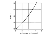
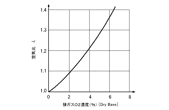
このような特性を有するバイオガスを一定発熱量で安定的に燃焼させるためには、理論空気比が近接するメタンを主成分とする補助燃料ガスを添加して混焼させることが効果的である。この場合、排ガス酸素濃度を一定に制御することにより、良好燃焼域の空気過剰率を維持することができる(図5※参照)。本発明はこのような作用を利用して、ガスホルダーの介在なしにバイオガスの安定的な燃焼を可能とするものである。
※「ガス燃焼の理論と実際」第1版p37図2・2、省エネルギーセンター、1992.10)
The operation of the present invention will be described below. The biogas after removing impurities is methane (CH 4) 50-60% and carbon dioxide (CO 2) 50-40%, as will be described later, and the composition ratio varies depending on fermentation conditions, passage of time, and the like. Moreover, since flammable components are only methane, the combustion calorific value of biogas also changes corresponding to the composition ratio change.
In order to stably burn the biogas having such characteristics with a constant calorific value, it is effective to add and co-fire auxiliary fuel gas mainly composed of methane having a close theoretical air ratio. In this case, the excess air ratio in the good combustion region can be maintained by controlling the exhaust gas oxygen concentration to be constant (see FIG. 5 *). The present invention utilizes such an action to enable stable combustion of biogas without the intervention of a gas holder.
* "Theory and practice of gas combustion" 1st edition, p37 Fig. 2.2, Energy Conservation Center, October 1992)
(2)前記補助燃料ガスが、13A都市ガスであることを特徴とする。
後述するように13A都市ガスはメタンを主成分とするため、補助燃料ガスとして最適であり、また、都市ガス供給網を容易に利用できるというメリットもある。
(2) The auxiliary fuel gas is 13A city gas.
As will be described later, since 13A city gas is mainly composed of methane, it is optimal as an auxiliary fuel gas, and there is also an advantage that the city gas supply network can be easily used.
また、本発明に係るバイオガス燃焼制御システムの燃焼制御方法は、
(3)上記各バイオガス燃焼制御システムにおいて、バイオガスと補助燃料ガスの流量比の増減により、燃焼装置が安定燃焼する空気比に対応する排気ガス中の酸素濃度範囲に制御することを特徴とする。
In addition, the combustion control method of the biogas combustion control system according to the present invention,
(3) In each of the above biogas combustion control systems, the oxygen concentration range in the exhaust gas corresponding to the air ratio at which the combustion apparatus stably burns is controlled by increasing or decreasing the flow ratio of the biogas and the auxiliary fuel gas. To do.
(4)上記(3)において、排気ガス中の酸素濃度範囲が、0vol%乃至11.1vol%であることを特徴とする。 (4) In the above (3), the oxygen concentration range in the exhaust gas is 0 vol% to 11.1 vol%.
(5)上記(3)において、排気ガス中の酸素濃度範囲が、5.5vol%乃至7.0vol%であることを特徴とする。 (5) In the above (3), the oxygen concentration range in the exhaust gas is 5.5 vol% to 7.0 vol%.
空気中のCH4の燃焼限界の空気比は 0.6−2.0(13A都市ガスもほぼ同じ)である(前掲文献p11、表1・9)。但し、空気比λ=0.6−1.0では不完全燃焼域であり対象外であるから、良好燃焼域として λ=1.0−2.0の範囲が適当である。この値に対応する酸素濃度範囲は0vol%乃至11.1vol%となる。
さらに、後述する実施例の検証データ(酸素濃度6.0vol%及び6.5vol%で検証)や燃焼装置の熱効率を考慮すると、酸素濃度範囲5.5vol%乃至7.0vol%(λ=1.32−1.45)がより好ましい。
The air ratio at the combustion limit of CH4 in the air is 0.6-2.0 (13A city gas is almost the same) (the aforementioned document p11, Tables 1 and 9). However, since the air ratio λ = 0.6-1.0 is an incomplete combustion region and is not a target, a range of λ = 1.0-2.0 is appropriate as a good combustion region. The oxygen concentration range corresponding to this value is 0 vol% to 11.1 vol%.
Furthermore, in consideration of verification data (verified with oxygen concentrations of 6.0 vol% and 6.5 vol%) and thermal efficiency of the combustion apparatus, which will be described later, an oxygen concentration range of 5.5 vol% to 7.0 vol% (λ = 1.5). 32-1.45) is more preferable.
本発明によれば、バイオガス流量・組成変動抑制のためのガスホルダーを必要としないため、設備の設置面積、建設費の大幅な低減化が可能という効果がある。
また、熱量測定が不要となり、制御に必要な機器・装置が簡素化されるため、イニシャルコスト、ランニングコストの低減化が可能という効果がある。
また、添加用ガスとして13A都市ガスを用いる発明にあっては、理論空気比がバイオガスと近接しているため、排ガス酸素濃度の一定制御が容易という効果がある。
According to the present invention, there is no need for a gas holder for suppressing the biogas flow rate / composition fluctuation, so that the installation area of the facility and the construction cost can be greatly reduced.
Further, since calorie measurement is not required and equipment and devices necessary for control are simplified, there is an effect that initial cost and running cost can be reduced.
Further, in the invention using 13A city gas as the additive gas, the theoretical air ratio is close to that of biogas, and therefore, there is an effect that constant control of exhaust gas oxygen concentration is easy.
以下、本発明の実施形態について、図1、2を参照してさらに詳細に説明する。なお、本発明の範囲は特許請求の範囲記載のものであって、以下の実施形態に限定されないことはいうまでもない。 Hereinafter, embodiments of the present invention will be described in more detail with reference to FIGS. Needless to say, the scope of the present invention is described in the claims and is not limited to the following embodiments.
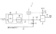
図1は、本発明の一実施形態に係るバイオガス燃焼制御システム1の構成を示す図である。
バイオガス燃焼制御システム1の燃焼系統は、メタン発酵槽2a、精製装置2bを含むバイオガス発生設備2と、熱量調整用ガスである都市ガスを供給する都市ガス供給ラインL2と、精製後のバイオガスと都市ガスとを混合するミキサー4と、熱量調整後の混合ガスを導入して蒸気を得るボイラー3と、を主要構成として備えている。また、本システムの燃焼制御系統は、ボイラー燃焼後の排気流路L4に配設され排ガス中の酸素濃度を計測する酸素濃度センサ6と、酸素濃度センサ6の検出値に基づいて都市ガス流量を制御する流量調整弁5と、制御系統を司る制御部7と、を主要構成とする。
FIG. 1 is a diagram showing a configuration of a biogas
The combustion system of the biogas
バイオガス発生設備2において、不図示の前処理装置で物理化学的処理(異物除去、加熱、破砕、場合によって酸処理、アルカリ処理等)を施したバイオマスをメタン発酵槽2aに送入し、嫌気性微生物により分解してメタン及び二酸化炭素を主成分とするガスを生成する。バイオガス中の水分及び不純物(硫化水素、シロキサン等)は精製装置2bにおいて除去する。精製後のバイオガスの組成比は原料組成や発酵槽2aの滞留時間によって変化するが、例えば表1の通りである。
In the
補助燃料ガスとして添加される都市ガスは、メタンを主成分としてプロパン、ブタン等の炭化水素ガスを含み、成分比の一例を表2に示す。
次に、ボイラー燃焼制御の内容について説明する。精製後のバイオガスと都市ガスはミキサー4において混合する。都市ガス添加量は後述する流量調整弁5の開度調整により行われる。混合ガスはボイラー3に供給され、ここでバーナ(図示せず)に供給される燃焼用空気により燃焼が行われる。後述するが、混合ガスと空気の比(燃焼空気比λ)は1.0−2.0となるように制御される。
Next, the content of boiler combustion control will be described. The purified biogas and city gas are mixed in the
次に図2を参照して、制御部8の指令に基づいて行われるボイラー燃焼制御の具体的内容について説明する。なお、本実施形態においてボイラー3は定格能力(最大燃焼量)で燃焼し、これに対応する所定の空気量が供給されるものとする。制御開始に伴い、バイオガスと都市ガスの混合ガスがボイラー3に供給される(S101)、初期状態において流量制御弁開度はデフォルト開度に設定されているものとする(S102)。次いでボイラー3の燃焼が開始される(S103)。
運転中は酸素濃度センサ6により、継続的に排ガス酸素濃度Cexが計測されている。Cexが上限、下限閾値範囲内(6.0%+α≧Cex≧6.0%−α)にある場合には(S105においてYES)、現状の流量制御弁開度が維持される(S107)。S105においてCex>6.0%+αの場合には燃料リーンの状態であるため、補助燃料ガス添加量を増大させるべく流量調整弁の開度を1段階大きくする(S106)。また、S105においてCex<6.0%−αの場合には燃料リッチの状態であるため、補助燃料ガス添加量を減少させるべく流量調整弁の開度を1段階小さくする(S108)。
以上の制御を所定の時間間隔で繰返し行うことにより、排ガス酸素濃度を(6.0±α)%、すなわち空気比λを1.3−1.4に制御することができる。
Next, with reference to FIG. 2, the specific content of the boiler combustion control performed based on the instruction | command of the
During operation, the exhaust gas oxygen concentration Cex is continuously measured by the
By repeating the above control at predetermined time intervals, the exhaust gas oxygen concentration can be controlled to (6.0 ± α)%, that is, the air ratio λ can be controlled to 1.3-1.4.
なお、本実施形態においては排ガス酸素濃度を6.0%±αに制御する例を示したが、所望の空気過剰率に対応する排ガス酸素濃度に設定することができる。
また、ボイラー燃焼を定格能力で運転する例を示したが、これに限らず部分負荷で運転する態様としてもよい。この場合もそれぞれの燃焼負荷の場合の空気過剰率に対応する排ガス酸素濃度に設定して、これに基づき制御することができる。
In the present embodiment, an example in which the exhaust gas oxygen concentration is controlled to 6.0% ± α has been shown. However, the exhaust gas oxygen concentration can be set to a desired excess air ratio.
Moreover, although the example which drive | operates boiler combustion with a rated capacity was shown, it is good also as an aspect operate | moved not only in this but by partial load. In this case as well, the exhaust gas oxygen concentration corresponding to the excess air ratio for each combustion load can be set and controlled based on this.
また、本実施形態では流量調整弁5を都市ガス供給ラインL2経路中に配設する例を示したが、混合ガスの供給ラインL3経路中に配設することもできる。
Further, in the present embodiment, the
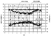
以下、本発明の1実施例の内容を説明する。図1と同様のシステム構成により、生ゴミと紙ごみを原料としてメタン発酵槽から発生するバイオガスを全量ボイラーに供給する条件で、排ガス中の酸素濃度を制御してボイラーを連続的に燃焼させた場合の混合ガスの発熱量の時間的変化を測定した。ボイラー燃焼排ガスのO2濃度設定は6.0%とした。この値は空気比λ=1.36に該当する。
制御検証結果(8日間)を図3に示す。投入原料の加温調節のためボイラーをオン・オフ運転とする原料投入時間(月曜から金曜の午前中約2時間:グラフ中の散在点)を除き、発熱量がほぼ一定(240MJ/h)に維持された。また、期間中ボイラーの失火・異常燃焼は見られなかった。(発生バイオガスの流量・濃度の変動により発生バイオガスの熱量が変動しているが、排ガス酸素濃度、ボイラー燃焼熱量が安定している。)
The contents of one embodiment of the present invention will be described below. With the same system configuration as in Fig. 1, the boiler is continuously burned by controlling the oxygen concentration in the exhaust gas under the condition that the biogas generated from the methane fermentation tank is supplied to the boiler using raw garbage and paper waste as raw materials. The time variation of the calorific value of the mixed gas was measured. The O2 concentration setting of the boiler combustion exhaust gas was 6.0%. This value corresponds to an air ratio λ = 1.36.
The control verification result (8 days) is shown in FIG. Except for the raw material charging time (about 2 hours in the morning from Monday to Friday: scattered points in the graph), the heating value is almost constant (240 MJ / h), except for the boiler on / off operation to control the heating of the raw material. Maintained. During the period, there was no boiler misfire or abnormal combustion. (The calorific value of the generated biogas fluctuates due to fluctuations in the flow rate and concentration of the generated biogas, but the exhaust gas oxygen concentration and boiler combustion calorific value are stable.)
引き続き3ヶ月間長期連続制御確認を行い、ボイラーの失火・異常燃焼がないことを確認した。
以上の結果から、本発明の制御を行うことによりメタン発酵槽の下流側にホルダーを設けることなく、熱量安定の燃焼ガスが得られることが実証された。
Subsequently, long-term continuous control was confirmed for 3 months, and it was confirmed that there was no misfire or abnormal combustion of the boiler.
From the above results, it was demonstrated that by controlling the present invention, a calorific stable combustion gas can be obtained without providing a holder on the downstream side of the methane fermentation tank.
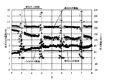
さらに、ボイラー燃焼排ガスのO2濃度を6.5%(λ=1.40)に設定し、その他は実施例1とど同一条件でボイラーを連続的に燃焼させ、混合ガスの発熱量の時間的変化を測定した。
制御検証結果を図4に示す。この条件においても発熱量はほぼ一定(210MJ/h)に維持され、期間中ボイラーの失火・異常燃焼も見られなかった。
Further, the O2 concentration of the boiler combustion exhaust gas was set to 6.5% (λ = 1.40), and the others were continuously burned under the same conditions as in Example 1, and the heating value of the mixed gas over time Changes were measured.
The control verification result is shown in FIG. Even under these conditions, the calorific value was maintained almost constant (210 MJ / h), and no misfire or abnormal combustion of the boiler was observed during the period.
本発明は、生ゴミ、紙ごみのみならず、下水汚泥、食品廃棄物、廃材、木材チップ等、種々のバイオマス原料を用いたバイオガス燃焼システムに広く適用可能である。 The present invention can be widely applied to biogas combustion systems using various biomass raw materials such as sewage sludge, food waste, waste materials, and wood chips as well as raw garbage and paper waste.
1・・・・バイオガス燃焼制御システム
2・・・・バイオガス発生設備
2a・・・メタン発酵槽
2b・・・精製装置
3・・・・ボイラー
4・・・・ミキサー
5・・・・流量調整弁
6・・・・酸素濃度センサ
7・・・・制御部
DESCRIPTION OF
Claims (5)
発生させたバイオガスに、メタンを主成分とする補助燃料ガスを添加した混合ガスを燃焼装置に送入する手段と、
燃焼装置において混合ガスの燃焼により生じる排気ガス中の酸素濃度を計測する酸素センサと、
該酸素センサによる酸素濃度計測値に基づき、補助燃料ガス添加量を増減する流量制御手段と、を備えて成り、
バイオガスの発熱量の時間的変化に関わらず、補助燃料ガス添加量の増減により混合ガスの燃焼発熱量を所望の範囲に制御可能に構成したことを特徴とするバイオガス燃焼制御システム。 A biogas combustion control system for directly sending biogas generated in a biogas generation facility to a combustion device without storing it in a gas holder,
Means for sending a mixed gas obtained by adding an auxiliary fuel gas mainly composed of methane to the generated biogas to the combustion device;
An oxygen sensor for measuring the oxygen concentration in the exhaust gas generated by the combustion of the mixed gas in the combustion device;
A flow rate control means for increasing or decreasing the amount of auxiliary fuel gas added based on the measured oxygen concentration value by the oxygen sensor,
A biogas combustion control system configured to be able to control a combustion heat generation amount of a mixed gas within a desired range by increasing or decreasing an auxiliary fuel gas addition amount regardless of a temporal change in the heat generation amount of the biogas.
バイオガスと補助燃料ガスの流量比の増減により、燃焼装置が安定燃焼する空気比に対応する排気ガス中の酸素濃度範囲に制御することを特徴とするバイオガス燃焼制御システムの燃焼制御方法。 The biogas combustion control system according to claim 1 or 2,
A combustion control method for a biogas combustion control system, characterized by controlling the oxygen concentration range in exhaust gas corresponding to the air ratio at which the combustion apparatus stably burns by increasing or decreasing the flow rate ratio of biogas and auxiliary fuel gas.
The combustion control method for a biogas combustion control system according to claim 3, wherein the oxygen concentration range is 5.5 vol% to 7.0 vol%.
Priority Applications (1)
| Application Number | Priority Date | Filing Date | Title |
|---|---|---|---|
| JP2011113722A JP2012242011A (en) | 2011-05-20 | 2011-05-20 | Biogas combustion control system, and combustion control method thereof |
Applications Claiming Priority (1)
| Application Number | Priority Date | Filing Date | Title |
|---|---|---|---|
| JP2011113722A JP2012242011A (en) | 2011-05-20 | 2011-05-20 | Biogas combustion control system, and combustion control method thereof |
Publications (1)
| Publication Number | Publication Date |
|---|---|
| JP2012242011A true JP2012242011A (en) | 2012-12-10 |
Family
ID=47463910
Family Applications (1)
| Application Number | Title | Priority Date | Filing Date |
|---|---|---|---|
| JP2011113722A Pending JP2012242011A (en) | 2011-05-20 | 2011-05-20 | Biogas combustion control system, and combustion control method thereof |
Country Status (1)
| Country | Link |
|---|---|
| JP (1) | JP2012242011A (en) |
Cited By (4)
| Publication number | Priority date | Publication date | Assignee | Title |
|---|---|---|---|---|
| JP2016020793A (en) * | 2014-07-15 | 2016-02-04 | 三浦工業株式会社 | Boiler device |
| JP2017155155A (en) * | 2016-03-03 | 2017-09-07 | 東京瓦斯株式会社 | Bio gas refining system and bio gas refining method |
| US11247169B2 (en) | 2016-03-09 | 2022-02-15 | Renaissance Energy Research Corporation | Combustion system |
| JP7064070B1 (en) | 2021-02-26 | 2022-05-10 | 三菱重工業株式会社 | Fuel cell fuel gas supply device |
Citations (11)
| Publication number | Priority date | Publication date | Assignee | Title |
|---|---|---|---|---|
| JPH1145726A (en) * | 1997-07-25 | 1999-02-16 | Toshiba Corp | Fuel cell power generating installation |
| JP2000090953A (en) * | 1998-09-16 | 2000-03-31 | Sapporo Breweries Ltd | Fuel cell power generation facility |
| JP2001055932A (en) * | 1999-08-16 | 2001-02-27 | Toshiba Corp | Gas engine system and operation method therefor |
| JP2001055952A (en) * | 1999-08-16 | 2001-02-27 | Toshiba Corp | Gas engine system |
| JP2004316529A (en) * | 2003-04-15 | 2004-11-11 | Tokyo Gas Co Ltd | Gas fuel feeding mechanism |
| JP2005030302A (en) * | 2003-07-14 | 2005-02-03 | Tokyo Gas Co Ltd | Gas engine, and method for controlling the same |
| JP2006511923A (en) * | 2002-12-19 | 2006-04-06 | ユーティーシー フューエル セルズ,エルエルシー | Fuel mixing control for fuel cell generators operating with multiple fuels |
| JP2007100581A (en) * | 2005-10-04 | 2007-04-19 | Nishishiba Electric Co Ltd | Engine driving work device |
| JP2009036111A (en) * | 2007-08-02 | 2009-02-19 | Meidensha Corp | Fuel change over method and fuel change over device for gas engine |
| JP2009208007A (en) * | 2008-03-04 | 2009-09-17 | Tokyo Gas Co Ltd | Method and apparatus for treating wastewater |
| JP2011081989A (en) * | 2009-10-06 | 2011-04-21 | Fuji Electric Holdings Co Ltd | Gas flow rate-measuring apparatus and fuel cell power generation system using the same |
-
2011
- 2011-05-20 JP JP2011113722A patent/JP2012242011A/en active Pending
Patent Citations (11)
| Publication number | Priority date | Publication date | Assignee | Title |
|---|---|---|---|---|
| JPH1145726A (en) * | 1997-07-25 | 1999-02-16 | Toshiba Corp | Fuel cell power generating installation |
| JP2000090953A (en) * | 1998-09-16 | 2000-03-31 | Sapporo Breweries Ltd | Fuel cell power generation facility |
| JP2001055932A (en) * | 1999-08-16 | 2001-02-27 | Toshiba Corp | Gas engine system and operation method therefor |
| JP2001055952A (en) * | 1999-08-16 | 2001-02-27 | Toshiba Corp | Gas engine system |
| JP2006511923A (en) * | 2002-12-19 | 2006-04-06 | ユーティーシー フューエル セルズ,エルエルシー | Fuel mixing control for fuel cell generators operating with multiple fuels |
| JP2004316529A (en) * | 2003-04-15 | 2004-11-11 | Tokyo Gas Co Ltd | Gas fuel feeding mechanism |
| JP2005030302A (en) * | 2003-07-14 | 2005-02-03 | Tokyo Gas Co Ltd | Gas engine, and method for controlling the same |
| JP2007100581A (en) * | 2005-10-04 | 2007-04-19 | Nishishiba Electric Co Ltd | Engine driving work device |
| JP2009036111A (en) * | 2007-08-02 | 2009-02-19 | Meidensha Corp | Fuel change over method and fuel change over device for gas engine |
| JP2009208007A (en) * | 2008-03-04 | 2009-09-17 | Tokyo Gas Co Ltd | Method and apparatus for treating wastewater |
| JP2011081989A (en) * | 2009-10-06 | 2011-04-21 | Fuji Electric Holdings Co Ltd | Gas flow rate-measuring apparatus and fuel cell power generation system using the same |
Cited By (6)
| Publication number | Priority date | Publication date | Assignee | Title |
|---|---|---|---|---|
| JP2016020793A (en) * | 2014-07-15 | 2016-02-04 | 三浦工業株式会社 | Boiler device |
| JP2017155155A (en) * | 2016-03-03 | 2017-09-07 | 東京瓦斯株式会社 | Bio gas refining system and bio gas refining method |
| US11247169B2 (en) | 2016-03-09 | 2022-02-15 | Renaissance Energy Research Corporation | Combustion system |
| JP7064070B1 (en) | 2021-02-26 | 2022-05-10 | 三菱重工業株式会社 | Fuel cell fuel gas supply device |
| WO2022181511A1 (en) * | 2021-02-26 | 2022-09-01 | 三菱重工業株式会社 | Fuel gas supply device for fuel battery |
| JP2022131495A (en) * | 2021-02-26 | 2022-09-07 | 三菱重工業株式会社 | Fuel gas supply device for fuel cell |
Similar Documents
| Publication | Publication Date | Title |
|---|---|---|
| Salomoni et al. | Enhanced methane production in a two-phase anaerobic digestion plant, after CO2 capture and addition to organic wastes | |
| JP2012242011A (en) | Biogas combustion control system, and combustion control method thereof | |
| KR20080038229A (en) | Fuel cell system and method for the operation of a reformer | |
| Ishikawa et al. | Load response of biogas CHP systems in a power grid | |
| JP2009036111A (en) | Fuel change over method and fuel change over device for gas engine | |
| Song et al. | Upgrading the performance of high solids feeding anaerobic digestion of chicken manure under extremely high ammonia level | |
| JP2007100581A (en) | Engine driving work device | |
| JP2004278468A (en) | Fuel supplying system | |
| KR20150104368A (en) | Biomethane and Power Generation Unit by integrating membrane separation process and internal combustion engine | |
| JP4070115B2 (en) | Control method of dual fuel engine | |
| JP2004293465A (en) | Device and method for supplying fuel gas | |
| JPH11324714A (en) | Gas turbine plant and its operating method | |
| JP6652858B2 (en) | Biogas purification system and biogas purification method | |
| JP2002226878A (en) | Method and equipment for utilizing biogas | |
| JP6837937B2 (en) | Biogas supply methods, systems, and programs | |
| JP6789180B2 (en) | Biogas supply methods, systems, and programs | |
| JP7018733B2 (en) | Solid oxide fuel cell | |
| WO2015016049A1 (en) | Fuel-cell system | |
| JP2018112166A (en) | Output device | |
| JP2011089070A (en) | Gasification power generation system | |
| JP4622244B2 (en) | Operation control method of fuel cell power generator | |
| JP2009133256A (en) | Method for controlling dual fuel engine | |
| JP4479884B2 (en) | Power generation facility and power generation method using low calorie gas fuel | |
| KR101487014B1 (en) | Dual fuel engine system using biogas and control method thereof | |
| JP2010059900A (en) | Gas mixing device used in electric power generation system |
Legal Events
| Date | Code | Title | Description |
|---|---|---|---|
| A621 | Written request for application examination |
Free format text: JAPANESE INTERMEDIATE CODE: A621 Effective date: 20130215 |
|
| A02 | Decision of refusal |
Free format text: JAPANESE INTERMEDIATE CODE: A02 Effective date: 20140318 |