JP2012241978A - Glow plug - Google Patents
Glow plug Download PDFInfo
- Publication number
- JP2012241978A JP2012241978A JP2011112468A JP2011112468A JP2012241978A JP 2012241978 A JP2012241978 A JP 2012241978A JP 2011112468 A JP2011112468 A JP 2011112468A JP 2011112468 A JP2011112468 A JP 2011112468A JP 2012241978 A JP2012241978 A JP 2012241978A
- Authority
- JP
- Japan
- Prior art keywords
- shaft
- power supply
- heater
- outer peripheral
- glow plug
- Prior art date
- Legal status (The legal status is an assumption and is not a legal conclusion. Google has not performed a legal analysis and makes no representation as to the accuracy of the status listed.)
- Granted
Links
Images


Classifications
-
- G—PHYSICS
- G01—MEASURING; TESTING
- G01M—TESTING STATIC OR DYNAMIC BALANCE OF MACHINES OR STRUCTURES; TESTING OF STRUCTURES OR APPARATUS, NOT OTHERWISE PROVIDED FOR
- G01M15/00—Testing of engines
- G01M15/04—Testing internal-combustion engines
- G01M15/08—Testing internal-combustion engines by monitoring pressure in cylinders
-
- F—MECHANICAL ENGINEERING; LIGHTING; HEATING; WEAPONS; BLASTING
- F23—COMBUSTION APPARATUS; COMBUSTION PROCESSES
- F23Q—IGNITION; EXTINGUISHING-DEVICES
- F23Q7/00—Incandescent ignition; Igniters using electrically-produced heat, e.g. lighters for cigarettes; Electrically-heated glowing plugs
- F23Q7/001—Glowing plugs for internal-combustion engines
- F23Q2007/004—Manufacturing or assembling methods
- F23Q2007/005—Manufacturing or assembling methods pressure sensors
Landscapes
- Engineering & Computer Science (AREA)
- Chemical & Material Sciences (AREA)
- Combustion & Propulsion (AREA)
- Mechanical Engineering (AREA)
- General Engineering & Computer Science (AREA)
- Physics & Mathematics (AREA)
- General Physics & Mathematics (AREA)
- Measuring Fluid Pressure (AREA)
Abstract
【課題】グロープラグのサイズの増大を防ぎつつ、圧力検出のための回路の実装面積を広げる技術を提供する。
【解決手段】グロープラグは、ヒータに電力を供給するヒータ通電シャフトと、ヒータ通電シャフトの軸方向端部に設けられ、ヒータ通電シャフトが軸方向に受ける圧力を電気信号に変換する圧力検出素子と、軸に対して圧力検出素子の外周を囲繞するとともに、圧力検出素子の信号出力端子を軸の外周側へ突出させる絶縁性の第一絶縁部材と、軸に対して第一絶縁部材の外周側に設けられ、ヒータ通電シャフトに接続されてヒータへ電力を供給する電力供給配線と、軸に対して電力供給配線の外周側に設けられ、信号出力端子に接続されて圧力検出端子の電気信号を処理する信号処理回路と、電力供給配線と信号処理回路との間に設けられ、信号処理回路と電力供給配線とを絶縁する第二絶縁部材とを備える。
【選択図】図5Provided is a technique for expanding a mounting area of a circuit for pressure detection while preventing an increase in the size of a glow plug.
A glow plug includes a heater energizing shaft that supplies electric power to a heater, and a pressure detecting element that is provided at an axial end of the heater energizing shaft and that converts the pressure that the heater energizing shaft receives in the axial direction into an electrical signal. An insulating first insulating member that surrounds the outer periphery of the pressure detecting element with respect to the shaft and that projects a signal output terminal of the pressure detecting element toward the outer peripheral side of the shaft; and an outer peripheral side of the first insulating member with respect to the shaft A power supply wiring that is connected to the heater energizing shaft and supplies power to the heater, and is provided on the outer peripheral side of the power supply wiring with respect to the shaft, and is connected to the signal output terminal to receive the electrical signal of the pressure detection terminal. A signal processing circuit to be processed, and a second insulating member that is provided between the power supply wiring and the signal processing circuit and insulates the signal processing circuit from the power supply wiring.
[Selection] Figure 5
Description
本発明は、電気的に加熱されるグロープラグに関する。 The present invention relates to an electrically heated glow plug.
ディーゼルエンジン等の内燃機関の始動を補助するグロープラグが知られている。グロープラグは、エンジンのシリンダに形成された貫通孔に挿入されて固定されるハウジングと、ハウジングの先端からシリンダの燃焼室(もしくは副燃焼室)内へ突出するヒータと、ハウジング内に設けられ、外部の電源からの電力をヒータへ供給する導体である電力供給シャフトとを有する。エンジンの始動前や始動時において、ヒータが電源から電力の供給を受けて発熱し、燃焼室内を加熱することにより、エンジンの始動を補助する。 A glow plug for assisting the start of an internal combustion engine such as a diesel engine is known. The glow plug is provided in the housing, a housing that is inserted and fixed in a through hole formed in the cylinder of the engine, a heater that protrudes from the front end of the housing into the combustion chamber (or auxiliary combustion chamber) of the cylinder, And a power supply shaft which is a conductor for supplying power from an external power source to the heater. Before starting the engine or at the time of starting the engine, the heater is supplied with electric power from the power source to generate heat, and heats the combustion chamber to assist in starting the engine.
更に、燃焼室内の燃焼圧をヒータから受けるピエゾ抵抗素子と、ピエゾ抵抗素子の抵抗値を検出する回路が設けられたプリント基板とがハウジング内に設けられたグロープラグが知られている(例えば、特許文献1参照)。 Further, there is known a glow plug in which a piezoresistive element that receives a combustion pressure in a combustion chamber from a heater and a printed circuit board provided with a circuit that detects a resistance value of the piezoresistive element are provided in a housing (for example, Patent Document 1).
しかしながら、圧力検出のための回路の実装面積を広げると、グロープラグのサイズが増大するという問題がある。 However, when the mounting area of the circuit for pressure detection is increased, there is a problem that the size of the glow plug increases.
本発明は、上述した問題点を解決するためになされたものであり、グロープラグのサイズの増大を防ぎつつ、圧力検出のための回路の実装面積を広げる技術を提供することを目的とする。 The present invention has been made to solve the above-described problems, and an object of the present invention is to provide a technique for expanding the mounting area of a circuit for pressure detection while preventing an increase in the size of a glow plug.
上述した課題を解決するため、本発明の一態様は、ヒータに電力を供給するヒータ通電シャフトと、前記ヒータ通電シャフトの軸方向端部に設けられ、前記ヒータ通電シャフトが軸方向に受ける圧力を電気信号に変換する圧力検出素子と、前記軸に対して前記圧力検出素子の外周を囲繞するとともに、前記圧力検出素子の信号出力端子を前記軸の外周側へ突出させる絶縁性の第一絶縁部材と、前記軸に対して前記第一絶縁部材の外周側に設けられ、前記ヒータ通電シャフトに接続されて前記ヒータへ電力を供給する電力供給配線と、前記軸に対して前記電力供給配線の外周側に設けられ、前記信号出力端子に接続されて前記圧力検出端子の電気信号を処理する信号処理回路と、前記電力供給配線と前記信号処理回路との間に設けられ、前記信号処理回路と前記電力供給配線とを絶縁する第二絶縁部材とを備えるグロープラグである。 In order to solve the above-described problem, an aspect of the present invention is provided with a heater energization shaft that supplies power to a heater, and an axial end portion of the heater energization shaft, and the pressure that the heater energization shaft receives in the axial direction. A pressure detecting element for converting the electric signal into an electric signal; and an insulating first insulating member that surrounds an outer periphery of the pressure detecting element with respect to the shaft and projects a signal output terminal of the pressure detecting element toward the outer peripheral side of the shaft A power supply wiring provided on the outer peripheral side of the first insulating member with respect to the shaft, connected to the heater energizing shaft and supplying power to the heater, and an outer periphery of the power supply wiring with respect to the shaft A signal processing circuit that is connected to the signal output terminal and processes an electrical signal of the pressure detection terminal, and is provided between the power supply wiring and the signal processing circuit. A processing circuit and the power supply wiring is a glow plug and a second insulating member for insulating.
以下、本発明の実施形態について図面を参照しつつ説明する。 Embodiments of the present invention will be described below with reference to the drawings.
まず、この実施形態のグロープラグ全体について説明する。 First, the entire glow plug of this embodiment will be described.
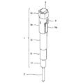
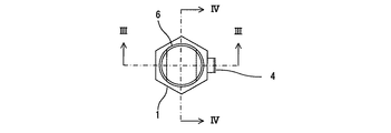
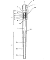
図1はグロープラグの斜視図であり、図2はこのグロープラグの平面図であり、図3はこのグロープラグの正面断面図であり、図4はこのグロープラグの左側面断面図である。ここで、図3は図2におけるIII−III矢視断面を示し、図4は図2におけるIV−IV矢視断面を示す。このグロープラグの一端は、図示しないシリンダの燃焼室内に挿入されている。以後、このグロープラグにおいて、燃焼室内に配置される一端(図1における下端)を先端と呼び、他端(図1における上端)を基端と呼ぶ。 1 is a perspective view of the glow plug, FIG. 2 is a plan view of the glow plug, FIG. 3 is a front sectional view of the glow plug, and FIG. 4 is a left side sectional view of the glow plug. Here, FIG. 3 shows a cross section taken along arrow III-III in FIG. 2, and FIG. 4 shows a cross section taken along arrow IV-IV in FIG. One end of this glow plug is inserted into a combustion chamber of a cylinder (not shown). Hereinafter, in this glow plug, one end (the lower end in FIG. 1) arranged in the combustion chamber is referred to as a distal end, and the other end (the upper end in FIG. 1) is referred to as a proximal end.
このグロープラグは、筒体を成すハウジング1と、先端がハウジング1外に突出しており基端がハウジング1内に位置しているヒータ2と、ハウジング1内に設けられており先端がヒータ2の基端に接続されている電力供給シャフト3と、ハウジング1内に設けられており先端が電力供給シャフト3の基端に接続されているセンサユニット4と、ハウジング1内に設けられており先端がセンサユニット4の基端に当接しているスペーサ5と、ハウジング1の基端部に固定されており先端がスペーサ5の基端に当接しているスクリュ6と、スペーサ5及びスクリュ6の内部を通っておりスペーサ5の先端からスクリュ6の基端まで延びる電源配線7とを有する。ヒータ2、電力供給シャフト3、スペーサ5、及びスクリュ6は、共通の中心軸を有する。電源配線7の基端側は、図示しない電源に接続されている。
This glow plug has a cylindrical housing 1, a
ハウジング1は、ハウジング1の先端に位置しており開口を有する先端部11と、先端が先端部11の基端に接続されており外周に雄ネジが形成されている雄ネジ部12と、先端が雄ネジ部12の基端に接続されており中空部に電力供給シャフト3を通しているシャフト格納部13と、先端がシャフト格納部13の基端に接続されており中空部にセンサユニット4を通しているセンサユニット格納部14と、先端がセンサユニット格納部14の基端に接続されておりハウジング1の基端に位置している工具係合部15とを有する。
The housing 1 includes a
シリンダの貫通孔の内周壁には雌ネジが形成されており、雄ネジ部12は、その雌ネジに螺合する。更に工具係合部15の外周壁は、中心軸を軸とする六角柱を成しており、スパナ等の工具に係合することができる。グロープラグをシリンダへ設置する際、ヒータ2及び先端部11をシリンダの貫通孔から燃焼室内へ挿入し、工具を用いて工具係合部15を中心軸周りに回転させることにより、雄ネジ部12は雌ネジ部に締結され、グロープラグはシリンダに固定される。
A female screw is formed on the inner peripheral wall of the through hole of the cylinder, and the
工具係合部15の内周壁には、雌ネジが形成されており、スクリュ6の外周壁には、その雌ネジに螺合する雄ネジが形成されている。更にこのスクリュ6の基端の外周壁には、スパナ等の工具に係合することができる2つの平面が形成されている。グロープラグを組み立てる際、ヒータ2と電力供給シャフト3とセンサユニット4とスペーサ5とがハウジング1内へ挿入された後、工具を用いてスクリュ6を中心軸周りに回転させることにより、スクリュ6はハウジング1に締結される。
A female screw is formed on the inner peripheral wall of the
センサユニット格納部14の側面には、センサユニット4の一部を延出させる開口が形成され、その開口は、アダプタ14aにより塞がれている。
An opening for extending a part of the
ヒータ2は、先端部11の開口から燃焼室内へ突出している。この例におけるヒータ2は、シースヒータである。ヒータ2は、外壁を形成する管2aと、管2aに設けられた螺旋状の発熱線2bと、管2a内に充填されている絶縁体2cとを有する。発熱線2bの一端は、電力供給シャフト3の先端に接続され、発熱線2bの他端は、ハウジング1を介してシリンダに接続されることにより接地される。なお、ヒータ2には、セラミックヒータ等の他の方式を適用することができる。
The
電力供給シャフト3の外周でヒータ2の基端側には、Oリング21が設けられている。このOリング21の外周がハウジング1の内周面に当接していることにより、燃焼室内の燃焼ガスがハウジング1の基端側に侵入することを防ぐ。なお、ヒータ2のハウジング1への取り付け構造によってはOリング21を使用しなくても燃焼ガスの侵入を防ぐことができる。また、ハウジング1と電力供給シャフト3は、互いに離間し、絶縁されている。
An O-
次に、センサユニット4について説明する。
Next, the
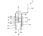
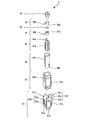
図5はセンサユニット4の正面図であり、図6はセンサユニット4の分解斜視図であり、図7は別の方向から見たセンサユニット4の分解斜視図である。センサユニット4は、先端がガイド41の底面に当接している電極31と、先端側の面が電極31の基端に当接している圧力検出素子32と、先端が圧力検出素子32の基端側の面に当接している電極33と、先端が電極33の基端に当接しているキャップ34と、中心軸に対して電極31と圧力検出素子32と電極33の夫々の外周を覆っているガイド41と、中心軸に対してガイド41の外側に設けられているリング42と、中心軸に対してリング42の外周を覆っているケース43と、中心軸に対してリング42の外側に設けられている信号処理回路51とを有する。電極31、圧力検出素子32、電極33、及びキャップ34の夫々は、中心軸上に設けられている。
FIG. 5 is a front view of the
ガイド41は、中心軸を軸とする中空円柱状に形成された絶縁体である。ガイド41の基端部には、鉤状のクリップ41bが設けられている。クリップ41bがキャップ34の基端を係止し、電力供給シャフト3がケース43の先端に当接し、ケース43の底面が電極31の先端側に当接することにより、電極31、圧力検出素子32、及び電極33はガイド41内に保持されている。また、ガイド41には、中心軸に平行な方向のスリット41a(第一スリット)が形成されている。ガイド41の先端においてスリット41aの先端は閉じており、ガイド41の基端においてスリット41aの基端は開いている。
The
リング42は、中心軸を軸とする中空円柱状に形成された導体である。また、リング42のうちスリット41aに重なる位置には、中心軸に平行な方向のスリット42a(第二スリット)が形成されている。リング42の先端においてスリット42aの先端は開いており、リング42の基端においてスリット42aの基端は開いている。即ち、リング42の中心軸に垂直な断面は、円環の一部が欠けた形状(C字状)である。
The
更にリング42の先端には、切り欠き42bが形成されている。電力供給シャフト3とリング42の接続前において、電力供給シャフト3の基端の外径はリング42の先端の内径以上である。電力供給シャフト3とリング42の接続時、電力供給シャフト3がリング42の先端へ挿入されることにより切り欠き42bの径が広がり、リング42の先端が電力供給シャフト3の基端を覆う。これにより、電力供給シャフト3の基端とリング42の先端は面接触し、スナップフィットにより接続される。更にリング42の基端が電源配線7の先端に接続されることにより、電源からの電力は、電源配線7、リング42、及び電力供給シャフト3を介してヒータ2へ供給される。リング42が中心軸に対してガイド41の外周を覆っていることにより、ヒータ2への電流を流す導体の断面積を確保することができる。また、電力供給シャフト3の基端とリング42の先端が面接触することにより、ヒータ2への電流を流す導体の断面積を確保することができる。
Further, a
ケース43は、筒体に形成された絶縁体である。ケース43の内周壁の中心軸に垂直な断面は、円の一部が直線により切り取られた形状(D字状)であり、リング42の外周壁と係合する。この係合により、リング42が中心軸周りに回転することが防止される。また、ケース43のうちスリット41aに重なる位置には、中心軸に平行な方向のスリット43a(第三スリット)が形成されている。ケース43の先端においてスリット43aの先端は閉じており、ケース43の基端においてスリット43aの基端は開いている。ケース43の外周壁には4つの平面が形成されている。これら4つの平面のうち、スリット42aの外周側に位置する平面にはスリット42aに重なるスリット43aが形成され、スリット43aに隣接する2つの平面には基板貼り付け部43c,43eが夫々形成され、スリット43aの反対側の平面には基板貼り付け部43dが形成されている。
The
電極31は、中心軸上に配置されており圧力検出素子32の先端側の面に当接する接点31aと、中心軸に垂直な方向へ突出するピン31bとを有する。同様に、電極33は、中心軸上に配置されており圧力検出素子32の基端側の面に当接する接点33aと、中心軸に垂直な方向へ突出するピン33bとを有する。ピン31b,33bは、スリット41a内を通ってガイド41の外へ突出し、スリット42a内を通ってリング42の外へ突出し、スリット43a内を通ってケース43の外へ突出している。また、スリット42aの幅はスリット41a,43aの幅より大きいため、ピン31b,33bの夫々とリング42は、互いに離間し、絶縁されている。
The
ガイド41においてスリット41aの基端が開いているため、組み立て時には、電極31と圧力検出素子32と電極33を基端側からガイド41内へ挿入することができる。また、リング42においてスリット42aの基端が開いているため、組み立て時には、電極31と圧力検出素子32と電極33とが設置されたガイド41を基端側からリング42内へ挿入することができる。また、ケース43においてスリット43aの基端が開いているため、組み立て時には、電極31と圧力検出素子32と電極33とが設置されたリング42を基端側からケース43内へ挿入することができる。
Since the base end of the
信号処理回路51は、中心軸に対してケース43の外周に巻き付けられているフレキシブル基板51aと、フレキシブル基板51aの一端に設けられた第1接続部51bと、フレキシブル基板51aを介して第1接続部51bに接続された部分回路51cと、フレキシブル基板51aを介して部分回路51cに接続された部分回路51dと、フレキシブル基板51aを介して部分回路51dに接続された部分回路51eと、フレキシブル基板51aを介して部分回路51dに接続されておりフレキシブル基板51aの他端に設けられた第2接続部51fとを有する。
The
フレキシブル基板51aの内周側の面は、基板貼り付け部43c,43d,43eへ接着されている。フレキシブル基板51a上で基板貼り付け部43cの外周側には部分回路51cが設けられ、フレキシブル基板51a上で基板貼り付け部43dの外周側には部分回路51dが設けられており、フレキシブル基板51a上で基板貼り付け部43eの外周側には部分回路51eが設けられている。第1接続部51bは、スリット43aに密着している。第2接続部51fは、センサユニット格納部14の開口とアダプタ14aの間隙からセンサユニット格納部14の外へ延出し、図示しない制御装置に接続されている。制御装置は例えばECU(Engine Control Unit)である。
The inner peripheral surface of the
第1接続部51bは、夫々貫通孔が形成されている素子接続端子51p,51qを有する。ケース43から突出したピン33bは、素子接続端子51pの貫通孔に接続される。同様に、ケース43から突出したピン31bは、素子接続端子51qの貫通孔に接続される。この構成により、圧力検出素子32から出力される電荷信号は、素子接続端子51p,51qへ与えられる。第2接続部51fは、夫々貫通孔が形成されている電源端子51rと接地端子51sと信号端子51tを有する。電源端子51rは、制御装置の電源供給端子へ接続され、制御装置から信号処理回路51への電力の供給を受ける。接地端子51sは、基準電位に接続される。信号端子51tは、制御装置の信号入力端子へ接続され、信号処理回路51による処理の結果を制御装置へ出力する。部分回路51c,51d,51eの夫々は、信号処理回路51の機能の一部を実現する。
The
ガイド41は、電極31、圧力検出素子32、電極33の夫々と、リング42との間を絶縁している。更にケース43は、リング42と信号処理回路51との間を絶縁している。これらの構成により、圧力検出素子32からの信号の経路とヒータ2への電力の経路との間は、絶縁されている。
The
圧力検出素子32の基端側の面は、電極33、キャップ34、スペーサ5、スクリュ6、及びハウジング1を介して、シリンダに固定されている。燃焼室内の燃焼圧は、ヒータ2、電力供給シャフト3、電極31を介して、圧力検出端子32の先端側の面を基端方向へ押圧する。これにより、圧力検出端子32は中心軸方向に圧縮され、先端側の面の変位に応じた電荷信号を電極31,33間に発生させる。信号処理回路51は例えばチャージアンプであり、圧力検出素子32から出力される微弱な電荷信号を電圧信号に変換して制御装置へ出力する。
The surface on the proximal end side of the
ヒータ2への電力の配線であるリング42が中心軸に対して圧力検出素子32の外周を覆うように設けられ、更に信号処理回路51が中心軸に対してリング42の外周を覆うように設けられていることにより、センサユニット4及びグロープラグの径の増大を防ぐことができる。
A
また、フレキシブル基板51aがケース43上に巻き付けられることにより、部分回路51c,51d,51eはケース43の外周壁上に設けられている。信号処理回路51の回路部品が一つのリジッド基板上に実装される場合と比較すると、この実施形態は、グロープラグの径を小さくすることができる。また、信号処理回路51の回路部品が一つのリジッド基板上に実装される場合と比較して、グロープラグの径を等しくすれば、この実施形態は、信号処理回路51の実装面積を広くすることができる。これにより、ASIC(Application Specific Integrated Circuit)等の高価な集積回路を用いて信号処理回路51を小型化する必要がなくなり、信号処理回路51のコストを抑えることができる。
Further, the
第一絶縁部材は例えば、ガイド41である。なお、第一絶縁部材には、スリットの代わりに他の形状の開口や切り欠きが形成されていても良い。また、第一絶縁部材は、複数の絶縁体により実現されても良い。この場合、第一絶縁部材の複数の絶縁体の間にピン31b,33bを通しても良い。電力供給配線は例えば、リング42である。なお、電力供給配線には、スリットの代わりに他の形状の開口や切り欠きが形成されていても良い。また、電力供給配線は、夫々が電源配線7と電力供給シャフト3とを接続する複数の導体により実現されても良い。この場合、電力供給配線の複数の導体の間にピン31b,33bを通しても良い。第二絶縁部材は例えば、ケース43である。なお、第二絶縁部材には、スリットの代わりに他の形状の開口や切り欠きが形成されていても良い。また、第二絶縁部材は、複数の絶縁体により実現されても良い。この場合、第二絶縁部材の複数の絶縁体の間にピン31b,33bを通しても良い。
The first insulating member is, for example, a
圧力検出素子32の材料として、例えば酸化亜鉛などの圧電体が用いられる。本実施形態では、電極31の接点31a、電極33の接点33aは、圧力検出素子である酸化亜鉛の分極軸と直交する上下の面(C面)、いわゆる結晶面方位(0,0,0,1)面にそれぞれ当接しており、本実施形態は、酸化亜鉛が分極軸方向に圧縮された際にC面に電荷を発生する特性(圧電縦効果)を利用している。同様に圧電縦効果を有する圧電体として、水晶、ニオブ酸リチウム、タンタル酸リチウム、チタン酸バリウム、チタン酸鉛、チタン酸ジルコン酸鉛、ニオブ酸鉛等があり、本実施形態と同様に分極軸と直交する上下の面に電極31,33を配置することで感度良く圧力を検出することができる。スペーサ5、キャップ34、ガイド41、ケース43の材料として、例えばポリフェニレンサルファイドなどの樹脂が用いられる。スクリュ6、アダプタ14a、電極31,33の材料として、例えば硫黄快削鋼などの鋼材が用いられる。クリップ41bの材料として、例えばステンレス鋼などの鋼材が用いられる。リング42の材料として、例えばリン脱酸銅など電気伝導性の高い材料が用いられる。ハウジング1の材料として、例えば炭素鋼などの鋼材が用いられる。Oリング21の材料として、例えばフッ素ゴムなどのゴムが用いられる。
As a material of the
更に前述の実施形態には、ヒータに電力を供給するヒータ通電シャフトと、前記ヒータ通電シャフトの軸方向端部に設けられ、前記ヒータ通電シャフトが軸方向に受ける圧力を電気信号に変換する圧力検出素子と、該圧力検出素子の電気信号を処理する信号処理回路と、前記圧力検出素子を囲繞するとともに、前記圧力検出素子の信号出力端子を外周側へ突出させる絶縁性の第一絶縁部材と、前記第一絶縁部材の外周に設けられ、前記信号出力端子を通す第一スリットが形成された筒部を有し、前記ヒータ通電シャフトに接続されて前記ヒータに電力を供給する電力供給配線と、前記電力供給配線の外周面を覆うとともに、前記ヒータ通電シャフトと同軸を有し、前記信号出力端子を通す第二スリットが形成された筒体である第二絶縁部材と、前記第二絶縁部材の外周面に巻き付けられ、前記信号処理回路が形成されたフレキシブル基板とを備え、前記第一絶縁部材の外周側へ突出した前記信号処理端子は、前記第一スリットを通して前記電力供給配線の外周側へ突出し、前記第二スリットを通して前記第二絶縁部材の外周側へ突出し、前記信号処理回路に接続されている、グロープラグが開示されている。 Furthermore, in the above-described embodiment, a heater energizing shaft that supplies electric power to the heater, and a pressure detection that is provided at an axial end of the heater energizing shaft and converts the pressure that the heater energizing shaft receives in the axial direction into an electrical signal. An element, a signal processing circuit that processes an electrical signal of the pressure detection element, an insulating first insulating member that surrounds the pressure detection element and projects a signal output terminal of the pressure detection element to the outer peripheral side; A power supply wiring that is provided on the outer periphery of the first insulating member, has a cylindrical portion formed with a first slit through which the signal output terminal passes, and is connected to the heater energizing shaft and supplies power to the heater; A second insulating member that is a cylindrical body that covers the outer peripheral surface of the power supply wiring, is coaxial with the heater energizing shaft, and is formed with a second slit through which the signal output terminal passes. A flexible substrate wound around an outer peripheral surface of the second insulating member and formed with the signal processing circuit, and the signal processing terminal protruding to the outer peripheral side of the first insulating member is connected to the power through the first slit. A glow plug is disclosed that protrudes to the outer peripheral side of the supply wiring, protrudes to the outer peripheral side of the second insulating member through the second slit, and is connected to the signal processing circuit.
1 ハウジング、2 ヒータ、3 電力供給シャフト、4 センサユニット、5 スペーサ、6 スクリュ、11 先端部、12 雄ネジ部、13 シャフト格納部、14 センサユニット格納部、14a アダプタ、15 工具係合部、21 Oリング、31 電極、31a 接点、31b ピン、32 圧力検出素子、33 電極、33a 接点、33b ピン、34 キャップ、41 ガイド、41a スリット、41b クリップ、42 リング、42a スリット、43 ケース、43a スリット、43c,43d,43e 基板貼り付け部、51 信号処理回路、51a フレキシブル基板、51b 第1接続部、51c,51d,51e 部分回路、51f 第2接続部、51p,51q 素子接続端子、51r 電源端子、51s 接地端子、51t 信号端子。 DESCRIPTION OF SYMBOLS 1 Housing, 2 Heater, 3 Power supply shaft, 4 Sensor unit, 5 Spacer, 6 Screw, 11 Tip part, 12 Male thread part, 13 Shaft storage part, 14 Sensor unit storage part, 14a Adapter, 15 Tool engaging part, 21 O-ring, 31 electrode, 31a contact, 31b pin, 32 pressure detection element, 33 electrode, 33a contact, 33b pin, 34 cap, 41 guide, 41a slit, 41b clip, 42 ring, 42a slit, 43 case, 43a slit 43c, 43d, 43e Substrate pasting portion, 51 signal processing circuit, 51a flexible substrate, 51b first connection portion, 51c, 51d, 51e partial circuit, 51f second connection portion, 51p, 51q element connection terminal, 51r power supply terminal , 51s Ground terminal, 51 Signal terminal.
Claims (7)
前記ヒータ通電シャフトの軸方向端部に設けられ、前記ヒータ通電シャフトが軸方向に受ける圧力を電気信号に変換する圧力検出素子と、
前記軸に対して前記圧力検出素子の外周を囲繞するとともに、前記圧力検出素子の信号出力端子を前記軸の外周側へ突出させる絶縁性の第一絶縁部材と、
前記軸に対して前記第一絶縁部材の外周側に設けられ、前記ヒータ通電シャフトに接続されて前記ヒータへ電力を供給する電力供給配線と、
前記軸に対して前記電力供給配線の外周側に設けられ、前記信号出力端子に接続されて前記圧力検出端子の電気信号を処理する信号処理回路と、
前記電力供給配線と前記信号処理回路との間に設けられ、前記信号処理回路と前記電力供給配線とを絶縁する第二絶縁部材と
を備えたグロープラグ。 A heater energizing shaft for supplying power to the heater;
A pressure detecting element that is provided at an axial end portion of the heater energizing shaft and converts the pressure that the heater energizing shaft receives in the axial direction into an electrical signal;
An insulating first insulating member that surrounds the outer periphery of the pressure detecting element with respect to the shaft, and that projects a signal output terminal of the pressure detecting element toward the outer peripheral side of the shaft;
A power supply line provided on the outer peripheral side of the first insulating member with respect to the shaft, connected to the heater energizing shaft and supplying power to the heater;
A signal processing circuit that is provided on the outer peripheral side of the power supply wiring with respect to the shaft and is connected to the signal output terminal to process an electrical signal of the pressure detection terminal;
A glow plug, comprising: a second insulating member provided between the power supply wiring and the signal processing circuit and insulating the signal processing circuit and the power supply wiring.
請求項1に記載のグロープラグ。 The signal output terminal has two terminals that sandwich the pressure detection element in the axial direction.
The glow plug according to claim 1.
前記二つの端子は、前記第一スリットを通して前記軸の外周側へ突出している、
請求項2に記載のグロープラグ。 The first insulating member is a cylinder formed with a first slit parallel to the axis,
The two terminals protrude to the outer peripheral side of the shaft through the first slit,
The glow plug according to claim 2.
前記二つの端子は、前記第二スリットを通して前記軸の外周側へ突出している、
請求項2又は請求項3に記載のグロープラグ。 The power supply wiring is a cylinder formed with a second slit parallel to the axis,
The two terminals protrude to the outer peripheral side of the shaft through the second slit,
The glow plug according to claim 2 or claim 3.
前記二つの端子は、前記第三スリットを通して前記軸の外周側へ突出している、
請求項2乃至請求項4のいずれか一項に記載のグロープラグ。 The second insulating member is a cylinder formed with a third slit parallel to the axis,
The two terminals protrude to the outer peripheral side of the shaft through the third slit,
The glow plug according to any one of claims 2 to 4.
前記信号処理回路は、複数の部分回路を有し、
前記複数の部分回路は、前記複数の平面上に夫々設けられている、
請求項1乃至請求項5のいずれか一項に記載のグロープラグ。 A plurality of planes are formed on the outer peripheral wall of the second insulating member with respect to the axis,
The signal processing circuit has a plurality of partial circuits,
The plurality of partial circuits are respectively provided on the plurality of planes.
The glow plug according to any one of claims 1 to 5.
前記フレキシブル基板は、前記軸に対して前記第二絶縁部材の外周壁に巻き付けられている、
請求項1乃至請求項6のいずれか一項に記載のグロープラグ。 The signal processing circuit has a flexible substrate,
The flexible substrate is wound around an outer peripheral wall of the second insulating member with respect to the shaft.
The glow plug according to any one of claims 1 to 6.
Priority Applications (4)
| Application Number | Priority Date | Filing Date | Title |
|---|---|---|---|
| JP2011112468A JP5854638B2 (en) | 2011-05-19 | 2011-05-19 | Glow plug |
| PCT/JP2012/062351 WO2012157622A1 (en) | 2011-05-19 | 2012-05-15 | Glow plug |
| US14/115,974 US8966963B2 (en) | 2011-05-19 | 2012-05-15 | Glow plug |
| EP12785133.5A EP2711631B1 (en) | 2011-05-19 | 2012-05-15 | Glow plug |
Applications Claiming Priority (1)
| Application Number | Priority Date | Filing Date | Title |
|---|---|---|---|
| JP2011112468A JP5854638B2 (en) | 2011-05-19 | 2011-05-19 | Glow plug |
Publications (2)
| Publication Number | Publication Date |
|---|---|
| JP2012241978A true JP2012241978A (en) | 2012-12-10 |
| JP5854638B2 JP5854638B2 (en) | 2016-02-09 |
Family
ID=47176939
Family Applications (1)
| Application Number | Title | Priority Date | Filing Date |
|---|---|---|---|
| JP2011112468A Expired - Fee Related JP5854638B2 (en) | 2011-05-19 | 2011-05-19 | Glow plug |
Country Status (4)
| Country | Link |
|---|---|
| US (1) | US8966963B2 (en) |
| EP (1) | EP2711631B1 (en) |
| JP (1) | JP5854638B2 (en) |
| WO (1) | WO2012157622A1 (en) |
Cited By (1)
| Publication number | Priority date | Publication date | Assignee | Title |
|---|---|---|---|---|
| FR3024542A1 (en) * | 2014-07-31 | 2016-02-05 | Continental Automotive France | SUPPORT OF AN ELECTRONIC MODULE OF A PRESSURE MEASURING SENSOR |
Families Citing this family (1)
| Publication number | Priority date | Publication date | Assignee | Title |
|---|---|---|---|---|
| DE102016114929B4 (en) * | 2016-08-11 | 2018-05-09 | Borgwarner Ludwigsburg Gmbh | pressure measuring glow |
Citations (8)
| Publication number | Priority date | Publication date | Assignee | Title |
|---|---|---|---|---|
| JPH08232825A (en) * | 1995-02-22 | 1996-09-10 | Unisia Jecs Corp | Ignition device with integrated combustion pressure sensor |
| JP2001241372A (en) * | 1999-12-24 | 2001-09-07 | Denso Corp | Combustion pressure sensor structure |
| JP2005207721A (en) * | 2003-12-24 | 2005-08-04 | Denso Corp | Glow plug |
| JP2006266526A (en) * | 2005-03-22 | 2006-10-05 | Ngk Spark Plug Co Ltd | Glow plug with combustion pressure detection mechanism and method for manufacturing glow plug with combustion pressure detection function |
| JP2006307834A (en) * | 2005-03-31 | 2006-11-09 | Ngk Spark Plug Co Ltd | Combustion pressure sensor and glow plug provided with the same |
| JP2008020176A (en) * | 2006-06-14 | 2008-01-31 | Ngk Spark Plug Co Ltd | Sensor built-in glow plug |
| JP2008545915A (en) * | 2005-05-17 | 2008-12-18 | ローベルト ボツシユ ゲゼルシヤフト ミツト ベシユレンクテル ハフツング | Electrical connection device for connecting the sensor element and the evaluation circuit |
| JP2010190445A (en) * | 2009-02-16 | 2010-09-02 | Mikuni Corp | Glow plug including combustion pressure sensor |
Family Cites Families (12)
| Publication number | Priority date | Publication date | Assignee | Title |
|---|---|---|---|---|
| DE60029550T2 (en) | 1999-12-24 | 2007-07-26 | Denso Corp., Kariya | Combustion pressure sensor |
| JP2004278934A (en) * | 2003-03-17 | 2004-10-07 | Ngk Spark Plug Co Ltd | Glow plug with combustion pressure detection function |
| JP3942176B2 (en) * | 2003-03-17 | 2007-07-11 | 日本特殊陶業株式会社 | Glow plug with combustion pressure detection function and manufacturing method thereof |
| FR2861836B1 (en) * | 2003-10-29 | 2006-03-10 | Siemens Vdo Automotive | PREHEATING CUP COMPRISING A PRESSURE SENSOR AND MOTOR THUS EQUIPPED |
| FR2869394B1 (en) * | 2004-04-27 | 2006-07-14 | Siemens Vdo Automotive Sas | PREHEATING CANDLE HEAD AND CORRESPONDING PIEZOELECTRIC PRESSURE SENSOR |
| JP2006300046A (en) * | 2004-08-05 | 2006-11-02 | Ngk Spark Plug Co Ltd | Glow plug with combustion pressure detection function |
| DE102006008350A1 (en) * | 2006-02-21 | 2007-08-30 | Robert Bosch Gmbh | Pressure measuring glow plug for arranging in chamber of internal combustion engine has centering element and pressure sensor assembled together, wherein centering section of centering element engages in recess of pressure sensor |
| DE102006008351A1 (en) * | 2006-02-21 | 2007-08-23 | Robert Bosch Gmbh | Pressure measuring device for arrangement in chamber of internal combustion engine, has housing and ends of sensor cage are connected to force transmission unit and fixing unit |
| DE102008009429A1 (en) * | 2007-03-15 | 2008-09-18 | Robert Bosch Gmbh | Seal for a glow plug |
| DE102008017110B3 (en) * | 2008-04-02 | 2009-09-10 | Beru Ag | pressure measuring glow |
| DE102009037375B3 (en) * | 2009-08-12 | 2011-03-03 | Beru Ag | glow plug |
| JP5654846B2 (en) * | 2010-01-22 | 2015-01-14 | 日本特殊陶業株式会社 | Combustion pressure sensor |
-
2011
- 2011-05-19 JP JP2011112468A patent/JP5854638B2/en not_active Expired - Fee Related
-
2012
- 2012-05-15 WO PCT/JP2012/062351 patent/WO2012157622A1/en not_active Ceased
- 2012-05-15 EP EP12785133.5A patent/EP2711631B1/en not_active Not-in-force
- 2012-05-15 US US14/115,974 patent/US8966963B2/en not_active Expired - Fee Related
Patent Citations (8)
| Publication number | Priority date | Publication date | Assignee | Title |
|---|---|---|---|---|
| JPH08232825A (en) * | 1995-02-22 | 1996-09-10 | Unisia Jecs Corp | Ignition device with integrated combustion pressure sensor |
| JP2001241372A (en) * | 1999-12-24 | 2001-09-07 | Denso Corp | Combustion pressure sensor structure |
| JP2005207721A (en) * | 2003-12-24 | 2005-08-04 | Denso Corp | Glow plug |
| JP2006266526A (en) * | 2005-03-22 | 2006-10-05 | Ngk Spark Plug Co Ltd | Glow plug with combustion pressure detection mechanism and method for manufacturing glow plug with combustion pressure detection function |
| JP2006307834A (en) * | 2005-03-31 | 2006-11-09 | Ngk Spark Plug Co Ltd | Combustion pressure sensor and glow plug provided with the same |
| JP2008545915A (en) * | 2005-05-17 | 2008-12-18 | ローベルト ボツシユ ゲゼルシヤフト ミツト ベシユレンクテル ハフツング | Electrical connection device for connecting the sensor element and the evaluation circuit |
| JP2008020176A (en) * | 2006-06-14 | 2008-01-31 | Ngk Spark Plug Co Ltd | Sensor built-in glow plug |
| JP2010190445A (en) * | 2009-02-16 | 2010-09-02 | Mikuni Corp | Glow plug including combustion pressure sensor |
Cited By (1)
| Publication number | Priority date | Publication date | Assignee | Title |
|---|---|---|---|---|
| FR3024542A1 (en) * | 2014-07-31 | 2016-02-05 | Continental Automotive France | SUPPORT OF AN ELECTRONIC MODULE OF A PRESSURE MEASURING SENSOR |
Also Published As
| Publication number | Publication date |
|---|---|
| US8966963B2 (en) | 2015-03-03 |
| EP2711631B1 (en) | 2017-11-01 |
| WO2012157622A1 (en) | 2012-11-22 |
| EP2711631A1 (en) | 2014-03-26 |
| US20140076039A1 (en) | 2014-03-20 |
| EP2711631A4 (en) | 2015-12-23 |
| JP5854638B2 (en) | 2016-02-09 |
Similar Documents
| Publication | Publication Date | Title |
|---|---|---|
| JP5901982B2 (en) | Detection system and detection device | |
| US10006883B2 (en) | Particulate sensor | |
| US20010008090A1 (en) | Combustion pressure sensor | |
| KR20090018648A (en) | Battery sensor unit and manufacturing method of the battery sensor unit | |
| JP5883290B2 (en) | Pressure detecting device and charge amplifier circuit | |
| WO2002044680A1 (en) | Charge amplifier for piezoelectric pressure sensor | |
| JP5975793B2 (en) | Combustion pressure sensor | |
| US20130008886A1 (en) | Glow plug | |
| JP5854638B2 (en) | Glow plug | |
| JP2001241372A (en) | Combustion pressure sensor structure | |
| WO2019049430A1 (en) | Fluid property detection device | |
| CN103988022A (en) | Glow plug for pressure measurement | |
| JP5614806B2 (en) | Shunt resistor device | |
| JP5339950B2 (en) | Glow plug with combustion pressure sensor | |
| JP5893920B2 (en) | Detection system and detection device | |
| JP3864871B2 (en) | Method and apparatus for inspecting internal combustion engine ignition device | |
| JP4019766B2 (en) | Ignition device for internal combustion engine and method of assembling the same | |
| JP5864330B2 (en) | Glow plug | |
| CN102713550A (en) | Ignition and pressure measuring devices for internal combustion engines | |
| JP4177342B2 (en) | Glow plug with combustion pressure detection mechanism and method for manufacturing glow plug with combustion pressure detection function | |
| JP7050646B2 (en) | Sensor | |
| JP2002081360A (en) | Ignition device for internal combustion engine | |
| JP2001123930A (en) | Mounting structure of glow plug | |
| JP2020085624A (en) | Pressure detector, circuit built-in member, and manufacturing method for pressure detector | |
| JP7008006B2 (en) | Pressure detector |
Legal Events
| Date | Code | Title | Description |
|---|---|---|---|
| A621 | Written request for application examination |
Free format text: JAPANESE INTERMEDIATE CODE: A621 Effective date: 20140519 |
|
| A131 | Notification of reasons for refusal |
Free format text: JAPANESE INTERMEDIATE CODE: A131 Effective date: 20150421 |
|
| A521 | Request for written amendment filed |
Free format text: JAPANESE INTERMEDIATE CODE: A523 Effective date: 20150605 |
|
| TRDD | Decision of grant or rejection written | ||
| A01 | Written decision to grant a patent or to grant a registration (utility model) |
Free format text: JAPANESE INTERMEDIATE CODE: A01 Effective date: 20151110 |
|
| A61 | First payment of annual fees (during grant procedure) |
Free format text: JAPANESE INTERMEDIATE CODE: A61 Effective date: 20151208 |
|
| R150 | Certificate of patent or registration of utility model |
Ref document number: 5854638 Country of ref document: JP Free format text: JAPANESE INTERMEDIATE CODE: R150 |
|
| R250 | Receipt of annual fees |
Free format text: JAPANESE INTERMEDIATE CODE: R250 |
|
| R250 | Receipt of annual fees |
Free format text: JAPANESE INTERMEDIATE CODE: R250 |
|
| R250 | Receipt of annual fees |
Free format text: JAPANESE INTERMEDIATE CODE: R250 |
|
| R250 | Receipt of annual fees |
Free format text: JAPANESE INTERMEDIATE CODE: R250 |
|
| LAPS | Cancellation because of no payment of annual fees |