JP2012240797A - Paper holder and printer - Google Patents
Paper holder and printer Download PDFInfo
- Publication number
- JP2012240797A JP2012240797A JP2011112788A JP2011112788A JP2012240797A JP 2012240797 A JP2012240797 A JP 2012240797A JP 2011112788 A JP2011112788 A JP 2011112788A JP 2011112788 A JP2011112788 A JP 2011112788A JP 2012240797 A JP2012240797 A JP 2012240797A
- Authority
- JP
- Japan
- Prior art keywords
- paper
- plate member
- sheet
- holder
- printer
- Prior art date
- Legal status (The legal status is an assumption and is not a legal conclusion. Google has not performed a legal analysis and makes no representation as to the accuracy of the status listed.)
- Granted
Links
Images


Abstract
Description
本発明は、排紙台に載置される用紙ホルダおよびプリンタに関する。 The present invention relates to a paper holder and a printer placed on a paper discharge tray.
プリンタから排出されてきた用紙を積載して収容するために、プリンタ本体の用紙排出口側に排紙台が設けられていることが多い。そして、印刷後の多数枚の用紙がプリンタから排出されて積層される場合には、通常、この排紙台に、用紙揃えが良好な状態で積層される(例えば特許文献1参照)。 In order to stack and store the sheets discharged from the printer, a sheet discharge stand is often provided on the sheet discharge port side of the printer main body. When a large number of printed sheets are discharged from the printer and stacked, the sheets are normally stacked on the discharge table in a state where the sheets are aligned well (see, for example, Patent Document 1).
ところで、多数枚の積層状態の用紙をプリンタの排紙台から取り出す際、用紙重量が大きいため、用紙を厚み方向に大きな力で押圧して挟持する必要があり、押圧力が不十分であると用紙揃えが悪化する。用紙に印字した後では印字面が滑りやすくなるため、この悪化が生じやすい。そして、用紙を反転させる必要があるときには、この用紙揃えの悪化は更に顕著となる。 By the way, when taking out a large number of stacked sheets from the paper discharge tray of the printer, the sheet weight is large, so it is necessary to press and hold the sheet with a large force in the thickness direction, and the pressing force is insufficient. Paper alignment deteriorates. Since the printing surface becomes slippery after printing on the paper, this deterioration is likely to occur. When it is necessary to invert the paper, the deterioration of the paper alignment becomes more remarkable.
この対策として、特許文献1では、排出された用紙を格納する格納容器を設け、この格納容器を持ち運び可能にすることが提案されている。しかし、格納容器の運搬時や格納容器からの用紙取り出し時に、やはり用紙揃えが悪化してしまうという問題があった。 As a countermeasure, Patent Document 1 proposes that a storage container for storing discharged paper is provided and the storage container can be carried. However, when transporting the storage container or taking out the paper from the storage container, there is still a problem that paper alignment deteriorates.
なお、A2サイズやB3サイズなどの大判印刷を行ったときには、重量が大きいことに加え、サイズが大きいため用紙を持った運搬者の手が胴体から離れてしまう。このため、重心が胴体に近い場合に比べ、運搬者にとって、運搬する際に用紙束を保持する力を入れ難く、しかもバランスを取り難いため、この問題は顕著となっていた。 In addition, when performing large format printing such as A2 size and B3 size, in addition to being heavy, the size of the large size causes the carrier's hand holding the paper to move away from the trunk. For this reason, compared with the case where the center of gravity is close to the body, it is difficult for the transporter to apply a force for holding the sheet bundle during transport, and it is difficult to achieve balance, and this problem has become prominent.
本発明は上記課題に鑑みてなされたものであり、印刷後の用紙を、用紙揃えを悪化させることなく容易に取り出すことができる用紙ホルダおよびプリンタを提供することを課題とする。 The present invention has been made in view of the above problems, and an object of the present invention is to provide a paper holder and a printer that can easily take out printed paper without deteriorating paper alignment.
上記目的を達成するために、本発明に係る用紙ホルダの第1の特徴は、プリンタの排紙台上に載置された用紙ホルダであって、排出されてきた用紙が上側に載せられる第1板材と、前記第1板材に上方から重ね合わせられ、前記第1板材との間で用紙を挟む第2板材と、前記第1板材と前記第2板材とで用紙を挟持するように、前記第1板材と前記第2板材とを相互に近づける方向に付勢する付勢手段と、を備えたことにある。 In order to achieve the above object, a first feature of a paper holder according to the present invention is a paper holder placed on a paper discharge tray of a printer, wherein the discharged paper is placed on the upper side. The first plate member is overlapped with the first plate member from above, and the second plate member sandwiches the sheet with the first plate member, and the first plate member and the second plate member sandwich the sheet. There is provided an urging means for urging the first plate member and the second plate member in a direction to approach each other.
本発明に係る用紙ホルダの第2の特徴は、前記第1板材および前記第2板材の一方は、一側縁部から他方の前記第1板材または前記第2板材に向けて延び出す用紙支え部を有し、前記第1板材および前記第2板材の他方には、前記用紙支え部を挿通させる挿通部が形成され、前記用紙支え部を下側にしたときに用紙を前記用紙支え部で支持可能とされていることを特徴とすることにある。 A second feature of the paper holder according to the present invention is that a paper support portion in which one of the first plate material and the second plate material extends from one side edge portion toward the other first plate material or the second plate material. The other of the first plate member and the second plate member is formed with an insertion portion through which the paper support portion is inserted, and the paper support portion is supported by the paper support portion when the paper support portion is at the lower side. It is characterized by being made possible.
本発明に係る用紙ホルダの第3の特徴は、前記用紙支え部を下側にしたときのホルダ上部に、人手で保持する手提げ部が設けられていることにある。 A third feature of the paper holder according to the present invention is that a hand-holding portion that is manually held is provided on an upper portion of the holder when the paper support portion is on the lower side.
本発明に係るプリンタの第1の特徴は、請求項1に記載の用紙ホルダを載置可能で、プリンタ本体の用紙排出口から排出される用紙を受ける排紙台と、前記排紙台を、前記用紙排出口側の排紙台端部回りに回動可能に保持する回動保持機構と、を備え、前記回動保持機構は、前記排紙台の位置を、前記用紙排出口から排出される用紙を前記排紙台で受ける用紙受け位置と、用紙排出方向端側の排紙台端部が前記用紙受け位置よりも下方に位置する用紙ホルダ取出し位置と、に切替可能であることにある。 A first feature of the printer according to the present invention is that the paper holder according to claim 1 can be placed, and a paper discharge tray that receives paper discharged from a paper discharge port of the printer main body, and the paper discharge tray, A pivot holding mechanism that pivotably holds around the end of the paper discharge port on the paper discharge port side, and the rotation holding mechanism discharges the position of the paper discharge table from the paper discharge port. It is possible to switch between a paper receiving position where the paper is received by the paper discharge stand and a paper holder taking-out position where the paper discharge stand end on the paper discharge direction end side is located below the paper receiving position.
本発明に係る用紙ホルダの第1の特徴によれば、印刷後の用紙を、用紙揃えを悪化させることなく容易に取り出すことができる用紙ホルダが実現される。 According to the first feature of the paper holder according to the present invention, a paper holder that can easily take out printed paper without deteriorating paper alignment is realized.
本発明に係る用紙ホルダの第2の特徴によれば、用紙を挟持した用紙ホルダを立設状態、すなわち用紙支え部を下側に位置させた状態にしても、簡単な構成で用紙を用紙支え部で確実に支えることができる。 According to the second feature of the paper holder according to the present invention, even when the paper holder that holds the paper is erected, that is, when the paper support is positioned on the lower side, the paper is supported with a simple configuration. Can be reliably supported by the department.
本発明に係る用紙ホルダの第3の特徴によれば、用紙を挟持した用紙ホルダを立設方向に向けた状態にして使用者が手提げで運搬することができる。 According to the third feature of the paper holder according to the present invention, the user can carry the paper holder holding the paper in the state in which the paper holder is held in the standing direction.
本発明に係るプリンタの第1の特徴によれば、排紙台を用紙受け位置に位置させて用紙を受けた後に用紙ホルダを組み立てて、排紙台を用紙ホルダ取出し位置にまで回動させることにより、用紙を挟持している用紙ホルダを排紙台から簡単に取り出すことができ、また、用紙ホルダの取り出しを考慮した排紙台の補強対策も行わなくても済む。 According to the first feature of the printer of the present invention, the paper discharge base is positioned at the paper receiving position, the paper holder is assembled after receiving the paper, and the paper discharge base is rotated to the paper holder extraction position. Thus, the paper holder holding the paper can be easily taken out from the paper discharge table, and it is not necessary to take measures to reinforce the paper discharge table in consideration of taking out the paper holder.
以下、本発明の実施の形態について説明する。なお、第2実施形態以下では、すでに説明したものと同様の構成要素には同じ符号を付してその説明を省略する。 Embodiments of the present invention will be described below. In the second and subsequent embodiments, the same components as those already described are denoted by the same reference numerals and description thereof is omitted.
なお、図面は模式的なものであり、寸法の比率等は現実のものとは異なることに留意すべきである。従って、具体的な寸法やその比率は以下の説明を参酌して判断すべきものである。又、図面相互間においても互いの寸法の関係や比率が異なる部分が含まれていることはもちろんである。 It should be noted that the drawings are schematic and dimensional ratios and the like are different from actual ones. Therefore, specific dimensions and ratios should be determined in consideration of the following explanation. Moreover, it is a matter of course that portions having different dimensional relationships and ratios are included between the drawings.
また、以下の説明では、用紙としてA2サイズやB3サイズなどを用いた大判印刷を行う例で説明するが、本発明は、通常サイズの用紙であっても適用可能である。また、以下の実施の形態で説明するプリンタは、例えば孔版印刷やインクジェットで印刷するプリンタであるが、他の種類のプリンタであってもよく、本発明ではプリンタの種類は特に限られない。 Further, in the following description, an example in which large format printing using A2 size or B3 size as the paper is described will be described, but the present invention is also applicable to normal size paper. In addition, the printer described in the following embodiment is a printer that performs printing by stencil printing or inkjet, for example, but may be other types of printers, and the type of printer is not particularly limited in the present invention.
[第1実施形態]
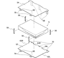
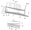
まず、第1実施形態について説明する。図1は、本実施形態のプリンタで、排紙部に積層された用紙(排紙)を運搬するために、用紙ホルダで用紙を保持することを示す斜視図である。また、図2(a)はプリンタの排紙部で用紙を受ける状態を示す側面図、図2(b)は、用紙を挟持した用紙ホルダを排紙部から取り出すために排紙部を下方へ回動させたことを示す斜視図である。また、図3(a)は図2(a)の部分拡大図であり、図3(b)は図2(b)の部分拡大図である。
[First Embodiment]
First, the first embodiment will be described. FIG. 1 is a perspective view illustrating that a sheet is held by a sheet holder in order to carry sheets (sheet discharge) stacked on a sheet discharge unit in the printer according to the present embodiment. 2A is a side view showing a state in which the paper is received by the paper discharge portion of the printer, and FIG. 2B is a view showing the paper discharge portion being lowered to take out the paper holder that holds the paper from the paper discharge portion. It is a perspective view which shows having rotated. 3 (a) is a partially enlarged view of FIG. 2 (a), and FIG. 3 (b) is a partially enlarged view of FIG. 2 (b).
本実施形態のプリンタ10は、プリンタ本体10Mの用紙排出口12から排出される用紙Sを受ける排紙台14と、この排紙台14を、用紙排出口側の排紙台端部14Mの回りに回動可能に保持する回動保持機構16と、を備えている。
The
排紙台14は、後述の用紙ホルダ50が載置可能な平板状の排紙台本体20と、排紙台本体20に立設され、排出された用紙Sを両サイドからそれぞれ支えるサイドフェンス22L、22Rと、排出された用紙Sを排出方向端側で支えるエンドフェンス24L、24Rとを備えている。本実施形態では、サイドフェンス22L、22R、および、エンドフェンス24L、24Rは排紙台本体20に着脱自在に立設しており、立設位置は、後述の用紙ホルダ50の寸法に合わせて設定されている。
The sheet discharge table 14 is a flat sheet discharge table
また、排紙台本体52には、後述の付勢部材56が入れられる孔状あるいは凹状の付勢部材挿通孔部26や付勢部材凹部27(図4も参照)が形成されている。
Further, the discharge tray
回動保持機構16は、排紙台本体20の両サイド側にそれぞれ係合する平板状の係合部材を備えている。図3(図4(a)、(d)も参照)に示すように、排紙台本体20の一方のサイドには係合凸部32が出没可能に突出しており、排紙台本体20の一方のサイド側に配置された係合部材30には、この係合凸部32に係合する係合孔部31が形成されている。排紙台本体20の他方のサイドについても同様の構成である。なお、係合凸部32の形状としては、係合を誘導する観点では円錐台状であることが有利であり、レバー42のストローク量を減らす観点では短円筒状であることが有利である。
The
係合孔部31としては、用紙排出口12から排出される用紙Sを受ける位置(以下、用紙受け位置という)に排紙台14を位置させるように係合凸部32が係合する係合孔部31Mと、排紙台14を用紙受け位置から下方へ回転させた位置(以下、用紙取り出し位置という)で係合凸部32が係合する係合孔部31Lと、排紙台14を用紙受け位置から上方へ回転させてプリンタ本体10M側に近接させて収納する位置(以下、収納位置という)で係合凸部32が係合する係合孔部31Uと、が形成されている。用紙受け位置では、用紙排出方向端側の排紙台端部14Eが、用紙排出口側の排紙台端部14Mよりもやや下方に位置している(図2(a)参照)。なお、サイドフェンス22L、22R、および、エンドフェンス24L、24Rは、排紙台14を収納位置に位置させる際に折りたたむ構成にされていてもよい。
As the
図4(a)〜(d)は、係合凸部32を出没させる機構を説明する斜視図である。排紙台14には、係合凸部32を排紙台本体20の両サイドで出没させる出没機構34が設けられている。出没機構34は、排紙台本体20の排出方向端側に延び出す手動操作部36と、係合凸部32を先端部に有する棒状係合部材38と、手動操作部36と棒状係合部材38とを接続しているワイヤ40と、を備えている。棒状係合部材38は排紙台14の両サイド側にそれぞれ配置されている。
FIGS. 4A to 4D are perspective views for explaining a mechanism for causing the engaging
手動操作部36は、使用者が親指以外の指を掛けるレバー42と親指を掛けるハンドル部44とを備えている。ワイヤ40は、このレバー42と棒状係合部材38とに接続されており、排紙台14の固定ピン18に掛けられることよって両端の方向が互いに異なる方向に向けられている。そして、棒状係合部材38は、排紙台14の両サイドから突出する方向へ圧縮コイルバネ(図示せず)によって付勢されている。
The
この構成により、係合凸部32が係合孔部31U、31M、31Rのいずれかに係合しているときに、使用者がレバー42とハンドル部44とに握る力を加えると、ワイヤ40が引っ張られ、係合凸部32が引っ込んで係合孔部31から外れる。また、使用者がレバー42から指を離す等してレバー42へ力を加えないときには、係合凸部32が突出していずれかの係合孔部に係合可能となる。
With this configuration, when the user applies a gripping force to the lever 42 and the
(用紙ホルダ)
以下、用紙ホルダ50について詳細に説明する。図5は、用紙ホルダの展開斜視図であり、図6は、用紙を挟持した用紙ホルダを、持ち運び可能な状態、すなわち立設させた状態にしたことを示す斜視図である。
(Paper holder)
Hereinafter, the
用紙ホルダ50は、用紙受け位置に配置された排紙台14上に載置される第1板材52と、第1板材52に上方から重ね合わせられ、第1板材52との間で用紙Sを挟む第2板材54と、第1板材52と第2板材54とで用紙Sを挟持するように、第1板材52と第2板材54とを相互に近づける方向に付勢する付勢部材56と、を備えている。従って、排紙台14が用紙受け位置に配置されているときには、第1板材52の上側に、プリンタ10から排出された用紙Sが載せられ、積層されていく。第1板材52および第2板材54の材質は、例えば、強度が比較的高くて軽量のプラスチックなどの樹脂部材であるが、ステンレスなどの金属製とすることも可能である。
The
第1板材52には、サイドフェンス22L、22Rがそれぞれ入り込むサイドフェンス用凹部62L、62Rが形成されている。サイドフェンス用凹部62L、62Rによって、第1板材52のサイド方向W(図1参照。用紙排出方向Fに直交する方向)の位置が規定されるようになっている。また、第1板材52には、エンドフェンス24L、24Rがそれぞれ入り込むサイドフェンス用凹部64L、64Rが形成されている。サイドフェンス用凹部64L、64Rによって、第1板材52の用紙排出方向Fの位置が規定されるようになっている。
Side fence recesses 62L and 62R into which the
このように、サイドフェンス用凹部62L、62R、エンドフェンス用凹部64L、64Rが形成されることによって、第1板材52は切り欠きを有するような形状とされている。そして、第1板材52を排紙台14上に配置しなくても、用紙排出口12から排出される用紙Sを排紙台14に揃えた状態で積層させることができる構成になっている。第2板材54についても同様である。
Thus, by forming the side fence
なお、図1では、第1板材52のサイド方向Wの中央位置の両側にそれぞれエンドフェンス24L、24Rが配置されている例を示しているが、この中央位置に1つのエンドフェンスが配置された構成としてもよい。
FIG. 1 shows an example in which the
第2板材54は、排出方向端側の側縁部から第1板材52に向けて延び出す用紙支え部68を有する。本実施形態では、用紙支え部68は3つの板状部で構成されている。そして、第1板材52には、この用紙支え部68を挿通させる用紙支え部挿通孔70が形成されている。この構成により、付勢部材56による付勢力によって、第1板材52と第2板材54とで用紙Sを挟持した状態で、用紙支え部68を下側(底側)にしたときには、用紙Sを用紙支え部68で支持可能となっている。なお、第2板材54が用紙支え部68を有し、第1板材52が用紙支え部挿通孔70を有する構成にすることも可能である。
The
付勢部材56としては、例えば、第1板材52および第2板材54に着脱可能な掛止め式テープが付いたバンド部材である。なお、一方の部材(例えば第1板材52)に端部が固定されていて、他方の部材(例えば第2板材54)に着脱自在とされたテープで取り付けられる構成にしてもよい。
The urging
また、第1板材52の用紙排出口側の側縁部、および、第2板材54の用紙排出口側の側縁部には、人手で保持する手提げ部74(図6参照)が設けられている。従って、この手提げ部74は、用紙ホルダ50が用紙Sを挟持した状態で用紙支え部68を下側にしたときに、用紙ホルダ50の上部側に位置する。
Further, a hand holding portion 74 (see FIG. 6) that is manually held is provided at the side edge portion of the
手提げ部74は、第1板材52の用紙排出口側の側縁部から用紙排出口側に2箇所で延び出す第1延出部76(図1も参照)と、第2板材54の用紙排出口側の側縁部から用紙排出口側に2箇所で延び出す第2延出部78(図1も参照)と、を備えている。第1延出部76および第2延出部78にはそれぞれ挿通孔80が形成されており、挿通孔80には使用者の指が掛けられる柔軟性の手提げ用部材82(例えば皮製の部材)が挿通可能となっている。手提げ用部材82には、例えば着脱自在な掛止め式のテープが付けられていて、挿通後にこの手提げ用部材82を簡単に無端状とすることが可能になっている。
The hand-held
なお、第1延出部76および第2延出部78は、直接に指が掛けられるような形状とされていてもよい。
In addition, the
(作用、効果)
以下、本実施形態の作用、効果について説明する。まず、排紙台14を用紙受け位置に配置する。そして、排紙台本体20に第1板材52を載せる。その際、サイドフェンス用凹部62L、62Rにサイドフェンス22L、22Rがそれぞれ入り込んで当接するとともに、エンドフェンス用凹部64L、64Rにエンドフェンス24L、24Rがそれぞれ入り込んで当接するように第1板材52を載置する。
(Function, effect)
Hereinafter, the operation and effect of the present embodiment will be described. First, the paper discharge table 14 is arranged at the paper receiving position. Then, the
この結果、第1板材52の両サイドの位置はサイドフェンス22L、22Rで規定される。また、用紙受け位置では用紙排出方向端側の排紙台端部14Eが用紙排出口側の排紙台端部14Mよりもやや下方に位置しているので、第1板材52の自重により第1板材52の用紙排出方向の位置がエンドフェンス24L、24Rで規定される。
As a result, the positions of both sides of the
その後、プリンタ10で印刷すると、プリンタ10から排出された用紙Sは第1板材52の上面に積層されていく。
Thereafter, when printing is performed by the
所定枚数の用紙Sが積層された後、第1板材52に上方から第2板材54を重ね合わせる。その際、用紙支え部68を用紙支え部挿通孔70に挿通させる。そして、付勢部材56を付勢部材挿通孔部26に挿通させることや付勢部材凹部27に入れることを行って第1板材52と第2板材54に取り付け、付勢力によって第1板材52と第2板材54とで用紙Sを挟持する。更に、第1板材52および第2板材54の挿通孔80に手提げ用部材82を挿通させて無端状とすることで、用紙ホルダ50の組み立てを完了する。この結果、用紙Sが揃った状態で用紙ホルダ50に挟持される。また、この状態では、用紙ホルダ50がエンドフェンス24L、24Rによって支えられており、エンドフェンス24L、24Rが用紙ホルダ50のストッパとしての役割を果たしている。
After the predetermined number of sheets S are stacked, the
次に、手動操作部36に指を掛けて握る。その際、レバー42に親指以外の指を掛け、ハンドル部44に親指を掛けて握る。この結果、レバー42が手前側に引き寄せられ、係合凸部32が引っ込んで係合孔部31から外れる。このとき、使用者が手動操作部36を握っているので、このように係合が外れても、排紙台14が急激に下方へ回転しまうことが防止される。
Next, the
係合が外れた後、使用者は、用紙ホルダ50および排紙台14の重量を利用して、排紙台14をゆっくり下方へ回転させる。そして、係合凸部32を係合孔部31Lに係合させることで、排紙台14を用紙取り出し位置に位置させる。この結果、用紙排出方向端側の排紙台端部14Eは、用紙受け位置に比べて下方に位置する。このとき、エンドフェンス24L、24Rが用紙ホルダ50のストッパとして作用し、用紙ホルダ50の落下が防止されている。
After the disengagement, the user slowly rotates the discharge table 14 downward using the weight of the
なお、用紙受け位置ではなく用紙取り出し位置に排紙台14を位置させた状態で、挿通孔80に手提げ用部材82を挿通させて無端状にしてもよく、これにより、挿通孔80に手提げ用部材82を挿通させ易い。
Note that the
そして、手提げ用部材82に指を通して用紙ホルダ50を持ち上げ、所定位置にまで運搬する。
Then, the
これにより、人手で用紙両側部を強く掴むことなく、用紙Sが揃った状態で所定位置にまで用紙Sを運搬することができる。このことは、印刷されていない裏面側に更に印刷する際、用紙ホルダ50をプリンタ10の所定位置に載置して、付勢部材56を取り外すとともに第1板材52を取り外すことで、用紙Sを揃えた状態で用紙Sを反転させて所定位置に短時間で簡単に配置することができ、大きな効果を奏する。
Accordingly, the paper S can be transported to a predetermined position in a state where the paper S is aligned without strongly grasping both sides of the paper manually. This means that when further printing is performed on the back side that is not printed, the
また、第1板材52と第2板材54とで用紙Sが挟持されているので、運搬時や保管時などで用紙ホルダ50が立設方向に向けられていても(すなわち用紙支え部68が下側に位置していても)、用紙Sが自重で曲がって変形してしまうことが防止される。
Further, since the paper S is sandwiched between the
また、排紙台14を用紙取り出し位置に位置させて用紙ホルダ50を取り出すことができる。従って、用紙ホルダ50を取り出す際に用紙ホルダ50がエンドフェンス24L、24Rと干渉し合うことが回避され、用紙ホルダ50の取り出しを考慮したエンドフェンス24L、24Rの保護対策、補強対策を行わなくても済む。また、用紙ホルダ50を取り出す際に排紙台14の用紙排出方向端側の排紙台端部14Eに大きな荷重がかかることも回避されるので、用紙ホルダ50の取り出しを考慮した排紙台14の補強対策も行わなくても済む。
Further, the
また、サイドフェンス22L、22Rおよびエンドフェンス24L、24Rの立設位置および寸法に合わせて、第1板材54にサイドフェンス用凹部62L、62R、エンドフェンス用凹部64L、64Rが形成されている。これにより、第1板材52を排紙台14上に配置しなくても、すなわち用紙ホルダ50を用いなくても、用紙排出口12から排出される用紙Sを排紙台14に揃えた状態で積層させることが可能になっている。印刷枚数が少ないときには、用紙ホルダ50を用いないほうが手間をかけずに短時間で印刷処理をすることができて有利である。
In addition, side fence recesses 62L and 62R and end fence recesses 64L and 64R are formed in the
また、用紙ホルダ50に手提げ部74を設けており、この手提げ部74で用紙ホルダ50を持つことにより、用紙ホルダ50に挟持された用紙Sを垂直方向(用紙ホルダ50が立設する方向)に向けた状態で運搬することができる。
Further, the
また、第1板材52に第2板材54を重ね合わせる際に、用紙支え部68を用紙支え部挿通孔70に挿通させることで用紙ホルダ50を組み立てており、用紙Sを挟持した用紙ホルダ50を立設方向に向けた際に、簡単な構成で用紙Sを用紙支え部68で支えることができる。なお、付勢部材56による用紙Sの挟持力が小さくても、この用紙支え部68により用紙揃え状態が悪化することが確実に防止される。
Further, when the
また、用紙ホルダ50を複数個用意しておき、印刷終了後に直ちに用紙ホルダ50を組み立てて排紙台14から移動させることで、用紙Sを排紙台14から移動させるのにかかる時間を短縮することができる。そして、印刷後の用紙Sを暫く放置する必要があるときには、保管場所にまで運搬してそのまま載置することができ、しかも用紙ホルダ50を立てた状態(用紙支え部68を下側にした状態)にして載置することができる。
Also, by preparing a plurality of
なお、以上の実施形態では、用紙排出方向端側の排紙台端部14Eが下がる方向に排紙台14が回転するときは緩やかに回転するように、ワンウェイ方向にダンパとして作用するギアを回動保持機構16に設けることが好ましい。
In the above embodiment, the gear acting as a damper is rotated in the one-way direction so that the sheet discharge table 14 rotates slowly when the sheet discharge table end 14E on the sheet discharge direction end side is lowered. It is preferable to provide the
また、第1板材52を配置していないときに使用者が印刷指令のボタンを押したときに、音声あるいは照明で、第1板材52を配置するように使用者に知らせる構成にしてもよい。更には、所定枚数の印刷を終了したときに、音声あるいは照明で、第2板材54を重ね合わせて用紙ホルダ50を組み立てる旨を使用者に知らせる構成にしてもよい。これらの場合、例えば、このような音声機あるいは警告灯を設け、プリンタ10の制御部(図示せず)でこれをコントロールする。
Further, when the user presses a print command button when the
また、図1に二点鎖線で示すように、第2板材54に空気抜き用孔86を配設してもよい。これにより、第2板材54を第1板材52に重ね合わせる際に、スムーズに重ね合わせることができ、また、第2板材54の軽量化を図ることもできる。更に、空気抜き用孔86を第1板材52に形成してよい。空気抜き用孔86の形状は、円形、楕円形など、種々の形状にすることが可能である。
Further, as shown by a two-dot chain line in FIG. 1, an
また、本実施形態では、重量が大きい大判の用紙Sの束を運搬し易いように、第1板材52の側縁部から2箇所で延び出す第1延出部76と、第2板材54の側縁部から2箇所で延び出す第2延出部78とを有する手提げ部74を設けた例で説明したが、重量や寸法が小さい場合には、側縁部の中央から1箇所のみで延び出す構成にしてもよい。
Further, in the present embodiment, the first extending
また、第1延出部76および第2延出部78を柔軟性の部材で構成してもよく、更には、第1延出部76および第2延出部78に代えて、着脱自在な掛止め式のテープ等で構成される着脱自在な手提げ部としてもよい。
In addition, the
また、本実施形態では、用紙支え部68を第2板材54が有し、第1板材52には、この用紙支え部68を挿通させる用紙支え部挿通孔70が形成されている例で説明したが、用紙支え部68を第1板材52が有し、第2板材52に、この用紙支え部68を挿通させる用紙支え部挿通孔70が形成されている構成にすることも可能である。
Further, in the present embodiment, the
[第2実施形態]
次に、第2実施形態について説明する。図7は、本実施形態の用紙ホルダを構成する第1板材の背面斜視図である。図8(a)は用紙受け位置に配置されている排紙部の側面断面図であり、図8(b)は図8(a)の部分拡大図である。
[Second Embodiment]
Next, a second embodiment will be described. FIG. 7 is a rear perspective view of the first plate member constituting the paper holder of the present embodiment. FIG. 8A is a side sectional view of the paper discharge unit disposed at the paper receiving position, and FIG. 8B is a partially enlarged view of FIG.
本実施形態の用紙ホルダ90では、第1板材92の裏面側(排紙台側)にL字状に突出する係止部94が形成されており、本実施形態のプリンタの排紙台96には、この係止部94が挿入される係止用孔部98が形成されている。この構成により、係止部94が係止用孔部98に挿入されて用紙ホルダ90が係止される構造になっている。
In the
これにより、第1実施形態に比べ、用紙取り出し位置で、排紙台端部14Eをもっと下方位置に下げた状態、すなわち用紙ホルダ90をもっと立設方向に近い状態にして、用紙ホルダ90を更に取り出し易くしても、用紙ホルダ90の落下が確実に防止される。
As a result, compared to the first embodiment, at the paper take-out position, the paper
なお、本実施形態では、用紙取り出し位置でエンドフェンス24L、24Rが用紙ホルダ90を支える必要がないので、エンドフェンス24L、24Rを用紙排出方向Fにスライド移動可能な構成にしてもよい。
In this embodiment, since the
10 プリンタ
10M プリンタ本体
12 用紙排出口
14 排紙台
14E 排紙台端部(一側縁部)
14M 排紙台端部
16 回動保持機構
50 用紙ホルダ
52 第1板材
54 第2板材
56 付勢部材
68 用紙支え部
70 用紙支え部挿通孔(挿通孔)
74 手提げ部
90 用紙ホルダ
92 第1板材
96 排紙台
S 用紙
DESCRIPTION OF
14M discharge tray end 16
74 Hand-carrying
Claims (4)
排出されてきた用紙が上側に載せられる第1板材と、
前記第1板材に上方から重ね合わせられ、前記第1板材との間で用紙を挟む第2板材と、
前記第1板材と前記第2板材とで用紙を挟持するように、前記第1板材と前記第2板材とを相互に近づける方向に付勢する付勢手段と、
を備えたことを特徴とする用紙ホルダ。 A paper holder placed on the output tray of the printer,
A first plate on which the discharged paper is placed on the upper side;
A second plate member that is superimposed on the first plate member from above and sandwiches paper with the first plate member;
An urging means for urging the first plate member and the second plate member toward each other so as to sandwich the sheet between the first plate member and the second plate member;
A paper holder characterized by comprising:
前記第1板材および前記第2板材の他方には、前記用紙支え部を挿通させる挿通部が形成され、
前記用紙支え部を下側にしたときに用紙を前記用紙支え部で支持可能とされていることを特徴とする請求項1に記載の用紙ホルダ。 One of the first plate member and the second plate member has a paper support portion extending from one side edge portion toward the other first plate member or the second plate member,
On the other of the first plate member and the second plate member, an insertion portion for inserting the paper support portion is formed,
The paper holder according to claim 1, wherein the paper can be supported by the paper support part when the paper support part is set to the lower side.
前記排紙台を、前記用紙排出口側の排紙台端部回りに回動可能に保持する回動保持機構と、
を備え、
前記回動保持機構は、前記排紙台の位置を、
前記用紙排出口から排出される用紙を前記排紙台で受ける用紙受け位置と、
用紙排出方向端側の排紙台端部が前記用紙受け位置よりも下方に位置する用紙ホルダ取出し位置と、
に切替可能であることを特徴とするプリンタ。 A paper discharge tray capable of placing the paper holder according to claim 1 and receiving paper discharged from a paper discharge port of the printer body;
A rotation holding mechanism for holding the discharge table so as to be rotatable around the end of the discharge table on the paper discharge port side;
With
The rotation holding mechanism determines the position of the discharge table,
A paper receiving position for receiving the paper discharged from the paper discharge port at the paper discharge stand;
A paper holder taking-out position where a paper discharge stand end on a paper discharge direction end side is located below the paper receiving position;
A printer characterized in that it can be switched between.
Priority Applications (1)
| Application Number | Priority Date | Filing Date | Title |
|---|---|---|---|
| JP2011112788A JP5740206B2 (en) | 2011-05-19 | 2011-05-19 | Paper holder and printer |
Applications Claiming Priority (1)
| Application Number | Priority Date | Filing Date | Title |
|---|---|---|---|
| JP2011112788A JP5740206B2 (en) | 2011-05-19 | 2011-05-19 | Paper holder and printer |
Publications (2)
| Publication Number | Publication Date |
|---|---|
| JP2012240797A true JP2012240797A (en) | 2012-12-10 |
| JP5740206B2 JP5740206B2 (en) | 2015-06-24 |
Family
ID=47462894
Family Applications (1)
| Application Number | Title | Priority Date | Filing Date |
|---|---|---|---|
| JP2011112788A Expired - Fee Related JP5740206B2 (en) | 2011-05-19 | 2011-05-19 | Paper holder and printer |
Country Status (1)
| Country | Link |
|---|---|
| JP (1) | JP5740206B2 (en) |
Citations (6)
| Publication number | Priority date | Publication date | Assignee | Title |
|---|---|---|---|---|
| JPS63147768A (en) * | 1986-12-10 | 1988-06-20 | Fuji Xerox Co Ltd | Sheet stacking device |
| JPH0359960U (en) * | 1989-08-28 | 1991-06-12 | ||
| JPH0664821A (en) * | 1992-08-24 | 1994-03-08 | Ricoh Co Ltd | Body housing type recording sheet stacking case |
| JPH10120275A (en) * | 1996-05-20 | 1998-05-12 | Ricoh Co Ltd | Paper treatment equipment |
| JP2001106417A (en) * | 1999-10-05 | 2001-04-17 | Oki Data Corp | Image forming device |
| JP2002137861A (en) * | 2000-09-04 | 2002-05-14 | Heidelberger Druckmas Ag | Device to store paper sheet stack |
-
2011
- 2011-05-19 JP JP2011112788A patent/JP5740206B2/en not_active Expired - Fee Related
Patent Citations (6)
| Publication number | Priority date | Publication date | Assignee | Title |
|---|---|---|---|---|
| JPS63147768A (en) * | 1986-12-10 | 1988-06-20 | Fuji Xerox Co Ltd | Sheet stacking device |
| JPH0359960U (en) * | 1989-08-28 | 1991-06-12 | ||
| JPH0664821A (en) * | 1992-08-24 | 1994-03-08 | Ricoh Co Ltd | Body housing type recording sheet stacking case |
| JPH10120275A (en) * | 1996-05-20 | 1998-05-12 | Ricoh Co Ltd | Paper treatment equipment |
| JP2001106417A (en) * | 1999-10-05 | 2001-04-17 | Oki Data Corp | Image forming device |
| JP2002137861A (en) * | 2000-09-04 | 2002-05-14 | Heidelberger Druckmas Ag | Device to store paper sheet stack |
Also Published As
| Publication number | Publication date |
|---|---|
| JP5740206B2 (en) | 2015-06-24 |
Similar Documents
| Publication | Publication Date | Title |
|---|---|---|
| JP5740206B2 (en) | Paper holder and printer | |
| JP6711780B2 (en) | Recording device | |
| US20080111875A1 (en) | Medium supplying mechanism, liquid ejecting device, and recording device | |
| US10272703B2 (en) | Printing apparatus | |
| JP4967776B2 (en) | Printer paper storage device | |
| JP2013014408A (en) | Image forming apparatus | |
| JP5787550B2 (en) | Containment device | |
| JPH10287019A (en) | Print apparatus | |
| JP2010070287A (en) | Paper sheet stacking device and recording device | |
| JP2005212907A (en) | Constitution of multiple plate members and case storing them | |
| JP2008100806A (en) | Medium support structure, medium supply device and recorder | |
| JP2016007776A (en) | Tape cassette, print tape for self laminate, and tape casette and tape printer | |
| JP2008023838A (en) | Medium feeding mechanism, liquid jet device and recorder | |
| JP2003200929A (en) | Sheet glass transporting pallet | |
| JPH08208096A (en) | Paper sheet delivery device for stencil duplicator | |
| JP2518414Y2 (en) | Automatic paper feeder | |
| KR970001925Y1 (en) | Stacker for a printer | |
| JP2007137652A (en) | Medium stacker, liquid jet device and recording device | |
| JP2006008192A (en) | Stacking method and apparatus for sheet-like material | |
| JP2003305912A (en) | Recorder | |
| JP2002283583A (en) | Ink-jet recording apparatus | |
| JP2008049624A (en) | Label printer | |
| JP2008105801A (en) | Ticket printing device | |
| JP2000063027A (en) | Paper ejection vessel, ejected paper container, ejection paper guide, and ejected paper housing device | |
| JP2003252515A (en) | Delivery receiving cover of printer, and printer |
Legal Events
| Date | Code | Title | Description |
|---|---|---|---|
| A621 | Written request for application examination |
Free format text: JAPANESE INTERMEDIATE CODE: A621 Effective date: 20140307 |
|
| A977 | Report on retrieval |
Free format text: JAPANESE INTERMEDIATE CODE: A971007 Effective date: 20141125 |
|
| A131 | Notification of reasons for refusal |
Free format text: JAPANESE INTERMEDIATE CODE: A131 Effective date: 20150106 |
|
| A521 | Written amendment |
Free format text: JAPANESE INTERMEDIATE CODE: A523 Effective date: 20150305 |
|
| TRDD | Decision of grant or rejection written | ||
| A01 | Written decision to grant a patent or to grant a registration (utility model) |
Free format text: JAPANESE INTERMEDIATE CODE: A01 Effective date: 20150407 |
|
| A61 | First payment of annual fees (during grant procedure) |
Free format text: JAPANESE INTERMEDIATE CODE: A61 Effective date: 20150427 |
|
| R150 | Certificate of patent or registration of utility model |
Ref document number: 5740206 Country of ref document: JP Free format text: JAPANESE INTERMEDIATE CODE: R150 |
|
| R250 | Receipt of annual fees |
Free format text: JAPANESE INTERMEDIATE CODE: R250 |
|
| R250 | Receipt of annual fees |
Free format text: JAPANESE INTERMEDIATE CODE: R250 |
|
| R250 | Receipt of annual fees |
Free format text: JAPANESE INTERMEDIATE CODE: R250 |
|
| LAPS | Cancellation because of no payment of annual fees |