JP2012229366A - Lubricant supplier - Google Patents
Lubricant supplier Download PDFInfo
- Publication number
- JP2012229366A JP2012229366A JP2011099766A JP2011099766A JP2012229366A JP 2012229366 A JP2012229366 A JP 2012229366A JP 2011099766 A JP2011099766 A JP 2011099766A JP 2011099766 A JP2011099766 A JP 2011099766A JP 2012229366 A JP2012229366 A JP 2012229366A
- Authority
- JP
- Japan
- Prior art keywords
- lubricant
- lubricated
- base material
- contact
- supply body
- Prior art date
- Legal status (The legal status is an assumption and is not a legal conclusion. Google has not performed a legal analysis and makes no representation as to the accuracy of the status listed.)
- Granted
Links
Images


Landscapes
- Rolling Contact Bearings (AREA)
- Lubricants (AREA)
- Bearings For Parts Moving Linearly (AREA)
Abstract
Description
本発明は、被潤滑部との接触部を有するとともに、多孔質海綿状に形成された合成樹脂からなる母材と、該母材の多孔質海綿状の空隙部に充填された潤滑剤とを有する潤滑剤供給体に関する。 The present invention comprises a base material made of a synthetic resin formed in a porous sponge shape and having a contact portion with a lubricated portion, and a lubricant filled in the porous sponge-like gap portion of the base material. The present invention relates to a lubricant supply body.
この種の潤滑剤供給体は、予め潤滑剤を多孔質海綿状の空隙部に含有させた合成樹脂から構成されている。そして、たとえば直動案内軸受,ボールねじ,オイルシール等の潤滑剤の供給を必要とする箇所に接触するように装着され、潤滑を必要とする箇所に対し、合成樹脂から徐々に滲出してくる潤滑剤を供給するようになっている(例えば特許文献1参照)。 This type of lubricant supply body is made of a synthetic resin in which a lubricant is previously contained in a porous sponge-like gap. And, for example, a linear guide bearing, a ball screw, an oil seal, etc. are mounted so as to come into contact with a place where the lubricant needs to be supplied, and gradually exude from the synthetic resin to the place where the lubrication is required. A lubricant is supplied (see, for example, Patent Document 1).
しかしながら、特許文献1に記載の潤滑剤供給体は、潤滑を必要とする箇所に対し、母材である合成樹脂から徐々に潤滑剤を滲出させることはできるものの、母材自体には被潤滑部との接触部とそれ以外の部分とに構成上の格別の創意がなされていないため、接触部付近に必要以上の潤滑剤が供給されると長期に亘って潤滑剤供給体を使用することができないという問題がある。
そこで、本発明は、このような問題点に着目してなされたものであって、被潤滑部との接触部からの潤滑剤の過剰な供給を抑制しつつも、被潤滑部に対して効率的且つ長期に亘って被潤滑部への安定した潤滑状態を維持することができる潤滑剤供給体を提供することを目的としている。
However, although the lubricant supply body described in Patent Document 1 can gradually exude the lubricant from the synthetic resin that is the base material to the portion that requires lubrication, the base material itself has a portion to be lubricated. The contact portion with the contact portion and the other portions are not particularly creative in terms of configuration, so if more lubricant than necessary is supplied near the contact portion, the lubricant supply body may be used for a long time. There is a problem that you can not.
Therefore, the present invention has been made paying attention to such problems, and while suppressing excessive supply of the lubricant from the contact portion with the lubricated portion, the present invention is efficient for the lubricated portion. An object of the present invention is to provide a lubricant supply body capable of maintaining a stable lubrication state for a lubricated part over a long period of time.
上記課題を解決するために、本発明は、被潤滑部との接触部を有するとともに、多孔質海綿状に形成された樹脂からなる母材と、該母材の多孔質海綿状の空隙部に充填された潤滑剤とを有する潤滑剤供給体であって、前記母材中の空隙部の割合を、前記被潤滑部との接触部から離れるにつれて接触部近傍よりも多くしたことを特徴としている。 In order to solve the above problems, the present invention has a contact portion with a lubricated portion, a base material made of a resin formed in a porous sponge shape, and a porous sponge-like gap portion of the base material. A lubricant supply body having a filled lubricant, wherein the ratio of the voids in the base material is increased from the vicinity of the contact part as the distance from the contact part with the part to be lubricated increases. .
本発明に係る潤滑剤供給体によれば、母材中の空隙部の割合が、前記被潤滑部との接触部から離れるにつれて接触部近傍よりも多くなっているので、被潤滑部との接触面付近から離れるにつれて潤滑剤(例えば油)の密度を高くし、接触面近傍では潤滑剤の密度を低くすることができる。そのため、被潤滑部との接触部近傍から被潤滑部への潤滑剤の過剰な供給を抑制しつつも、被潤滑部との接触部から離れた部分ではより多くの潤滑剤を蓄えておくことができる。したがって、被潤滑部に対して効率的且つ長期に亘って安定した潤滑状態を維持することができる。
ここで、発明に係る潤滑剤供給体において、前記空隙部を粗密にする領域が、段階的に構成されていることは好ましい。このような構成であれば、潤滑剤供給体の製造を容易とすることができる。
According to the lubricant supply body according to the present invention, since the ratio of the void portion in the base material is larger than the vicinity of the contact portion as it is away from the contact portion with the lubricated portion, the contact with the lubricated portion is increased. As the distance from the vicinity of the surface increases, the density of the lubricant (for example, oil) can be increased, and the density of the lubricant can be decreased near the contact surface. Therefore, while suppressing excessive supply of lubricant from the vicinity of the contact portion with the lubricated portion to the lubricated portion, more lubricant should be stored in a portion away from the contact portion with the lubricated portion. Can do. Therefore, it is possible to maintain a stable lubrication state efficiently and over a long period with respect to the lubricated part.
Here, in the lubricant supply body according to the present invention, it is preferable that the region for roughening the gap is configured in stages. With such a configuration, it is possible to easily manufacture the lubricant supply body.
上述のように、本発明に係る潤滑剤供給体によれば、母材中の空隙部の割合が、被潤滑部との接触部から離れるにつれて接触部近傍よりも多くなっているので、被潤滑部との接触部からの潤滑剤の過剰な供給を抑制しつつも、被潤滑部に対して効率的且つ長期に亘って安定した潤滑状態を維持することができる。 As described above, according to the lubricant supply body according to the present invention, since the ratio of the void portion in the base material increases from the vicinity of the contact portion as the distance from the contact portion with the lubrication portion increases, While suppressing excessive supply of the lubricant from the contact portion with the portion, it is possible to maintain a stable lubrication state efficiently and over a long period with respect to the lubricated portion.
以下、本発明に係る潤滑剤供給体を備える直動案内装置の一実施形態であるリニアガイドについて、図面を適宜参照しつつ説明する。
このリニアガイドは、図1に全体斜視図を示すように、外面に転動体転動溝3,3'を有した軸方向に延びる案内レール1と、この案内レール1を跨いで組み付けられるスライダ2とを備えている。スライダ2は、スライダ本体2Aと、エンドキャップ2Bとを備えて構成されている。
Hereinafter, a linear guide which is an embodiment of a linear motion guide device including a lubricant supply body according to the present invention will be described with reference to the drawings as appropriate.
As shown in the overall perspective view of FIG. 1, the linear guide includes a guide rail 1 that has rolling element rolling grooves 3 and 3 ′ on the outer surface and extends in the axial direction, and a
スライダ本体2Aには、その幅方向の両袖部4のレール側内側面に、案内レール1の転動体転動溝3,3'に対向する不図示の転動体転動溝が設けられている。また、スライダ本体2A袖部の肉厚部分には、軸方向に貫通する不図示の転動体戻し路が両袖部4の転動体転動溝に対向して形成されている。そして、エンドキャップ2Bは、スライダ本体2Aの転動体転動溝、およびこれに平行な転動体戻し路を相互に連通させるための不図示の湾曲路を有しており、これにより、転動体転動溝、転動体戻し路およびこれらの両端の一対の湾曲路とによって転動体の無限循環経路が形成されている。
The
そして、この無限循環経路内に多数の転動体(不図示)が装填されており、案内レール1に組み込まれたスライダ2は、多数の転動体の転動を介して案内レール1に沿ってスライド移動し、その移動中、転動体はスライダ内の転動体循環路を無限循環するようになっている。
ここで、スライダ2のレール方向両端の各エンドキャップ2Bの端面には、案内レール1との間の隙間の開口をシールするサイドシール10がそれぞれ取り付けられている。さらに、スライダ2のレール方向両端には、サイドシール10に重ねて、潤滑剤供給体としての潤滑剤含有ポリマ部材11が、補強板20とサイドシール10との間に挟んで組み付けられている。
A large number of rolling elements (not shown) are loaded in the endless circulation path, and the
Here,
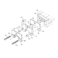
図2に分解斜視図を示すように、補強板20は、エンドキャップ2Bの外形に合せたほぼコ字形状の鋼板または合成樹脂板であり、その両袖部に取付ネジ21a,21bの貫通用の貫通孔2a、2bが形成されているとともに、それら両袖部を連結する連結部には、グリースニップル7用の貫通孔2cが形成されている。尚、この補強板20は、案内レール1とは接触していない。
As shown in an exploded perspective view in FIG. 2, the reinforcing
サイドシール10は、エンドキャップ2Bの外形に合ったほぼコ字形状の鋼板と、この鋼板と類似の形状を有してその外面に一体的に固着して形成されたニトリルゴムとから構成されている。そして、案内レール1と接触するシールリップ部Lは、スライダ2と案内レール1との隙間をシールできるように、案内レール1の断面形状に合せて案内レール1の上面1a及び外側面1b(図1参照)に摺接可能な形状に成形されるとともに、転動体転動溝3,3'(図1参照)にも摺接可能な形状に成形されている。また、このサイドシール10の両袖部に、取付ネジ貫通用の貫通孔10a,10bが形成され、両袖部を連結する連結部には、グリースニップル7用の貫通孔10cが形成されている。
The
この実施形態では、これらサイドシール10、潤滑剤含有ポリマ部材11、補強板20の三者が、取付用ネジ21a、21bをサイドシール10の貫通孔10a、10bと潤滑剤含有ポリマ部材11のスリーブ部材11A,11Bと補強板20の貫通孔2a、2b及びエンドキヤップ2Bのネジ貫通孔を通してスライダ本体2Aの取付用ネジ穴に螺合することにより、エンドキャップ2Bに一体に重ねて本休2Aに固定される。
In this embodiment, the three members of the
以下、上記潤滑剤含有ポリマ部材11について詳しく説明する。
この潤滑剤含有ポリマ部材11の形状は、図3および図4に示すように、エンドキャップ2Bの外形に合せた略コ字形状で、必要な潤滑剤量を確保するために所定の厚みを有している。その内面(被潤滑部側)の被潤滑部H(転動体転動溝3,3'、案内レール1の上面1a及び側面1b、以下同じ)との接触部S(突部12a,12bおよび突部13a,13bを含む内周に沿った面、以下同じ)の形状は、案内レール1の横断面の外形形状に略一致させてある。つまり、案内レール1の上面1a及び側面1bに沿う形状に形成されているとともに、案内レール1の上の転動体転動溝3'に対応する突部12a,12b、および、下の転動体転動溝3に対応する突部13a,13bがそれぞれ形成されて案内レール1の横断面外形形状に整合されている。なお、突部13a,13bの先端は、案内レール1の転動体転動溝3の逃げ加工溝に整合されて形成されている。
Hereinafter, the lubricant-containing
As shown in FIGS. 3 and 4, the shape of the lubricant-containing
また、潤滑剤含有ポリマ部材11には、その両袖部に、スライダのエンドキヤップ2Bヘの取付ネジの貫通用の貫通孔11a,11bが軸方向に切り開かれて形成されるとともに、それら両袖部を連結する連結部には、一部が軸方向に切開されたグリースニップル用の貫通孔11cが形成されている。
The lubricant-containing
そして、これらの貫通孔11a,11b及び11cのそれぞれには、図2に示されるように、リング状スリーブ部材11A,11B及び11Cが嵌め込まれるようになっている。このリング状スリーブ部材11A、11B及び11Cは、図3に示すように、潤滑剤含有ポリマ部材11の厚みよりも若干長く形成された短い円筒形状の部材であり(L2はL1より長い)、その外径は、貫通孔11a,11b及び11cに容易に嵌め込める程度の寸法となっている。これにより、潤滑剤含有ポリマ部材11をエンドキャップ2Bに装着する時にこれをねじで締め付ける際、部材11が必要以上に圧縮されるのを防ぎ潤滑剤が部材11から絞り出されることがないようにしている。
Then, as shown in FIG. 2, ring-
また、リング状スリーブ部材11A、11B及び11Cの外径は、貫通孔11a、11b及び11cの外径よりも大きく形成されている。このようにスリーブ径を大きくすることにより、潤滑剤含有ポリマ部材11の内面を絶えず案内レール1の外面に押し付けて密着させることができ、滲み出してくる潤滑剤を安定的に案内レール1に供給することができる。
Further, the outer diameters of the ring-shaped
ここで、本実施形態の例では、この潤滑剤含有ポリマ部材11は、高密度ポリエチレン(分子量1×10⁴〜5×10⁵)20重量%と超高分子量ポリエチレン(分子量1×10⁶〜5×10⁶)10重量%からなるポリエチレンを母材とし、この母材に潤滑剤として流動パラフィン70重量%を含有させたものを原料とした。そして、これを射出成形機を用いて一度可塑化(溶解)させた後、所定の金型に注入し、所定の遠心力を利用しつつ加圧して冷却固化させることで、図5に母材のイメージを拡大して示すように多孔質海綿状に形成されるとともに、母材中の空隙部Kの割合を、被潤滑部Hとの接触部Sから離れるにつれて接触部近傍よりも多くなるように成形している。これにより、図4および図5に示す矢印のように、母材中の空隙部Kの割合が、被潤滑部Hとの接触部Sから離れるにつれて接触部Sの近傍よりも多くなっているので、母材の多孔質海綿状の空隙部Kに充填される潤滑剤は、被潤滑部Hとの接触面付近から離れるにつれて潤滑剤の密度が高くなり、接触部Sの近傍では潤滑剤の密度が低くなる。
Here, in the example of the present embodiment, the lubricant-containing
次に、このリニアガイドに組み込んだ潤滑剤供給体の作用・効果について説明する。
上記構成のリニアガイドによれば、サイドシール10と案内レール1との間及びリニアガイド自体に必要な潤滑剤を供給するための潤滑剤供給体である潤滑剤含有ポリマ部材11が、被潤滑部Hとの接触部Sを有するとともに、多孔質海綿状に形成された樹脂からなる母材と、この母材の多孔質海綿状の空隙部Kに充填された潤滑剤とを有するものであり、母材中の空隙部Kの割合を、前記被潤滑部Hとの接触部Sから離れるにつれて接触部Sの近傍よりも多くしたので、被潤滑部Hとの接触部Sからの潤滑剤の過剰な供給を抑制しつつも、被潤滑部Hに対して効率的で安定した潤滑状態を維持することができる。
Next, the operation and effect of the lubricant supply body incorporated in the linear guide will be described.
According to the linear guide having the above-described configuration, the lubricant-containing
なお、本発明に係る潤滑剤供給体は、上記実施形態に限定されるものではなく、本発明の趣旨を逸脱しなければ種々の変形が可能である。
例えば上記実施形態では、潤滑剤含有ポリマ部材11は、サイドシール10及び補強板20に重ねて、両者の間に挟さまれて組み付けられている例で説明したが、これに限らず、潤滑剤含有ポリマ部材11は、案内レール1の外面に密着してサイドシール10と同様のシール機能をも果たし得るから、サイドシール10の代わりに補強板20を使用してもよく、または、補強板20を潤滑剤含有ポリマ部材11の表面のみに重ね、背面はエンドキャップ2Bの端面に直接当てるようにして装着してもよい。
The lubricant supply body according to the present invention is not limited to the above embodiment, and various modifications can be made without departing from the spirit of the present invention.
For example, in the above-described embodiment, the lubricant-containing
また、例えば上記実施形態では、潤滑剤含有ポリマ部材11は、母材中の空隙部Kの割合を、被潤滑部Hとの接触部Sから離れるにつれて接触部Sの近傍よりも多くするために、上述した原料を射出成形機を用いて一度可塑化(溶解)させた後、所定の金型に注入し、遠心力を利用しつつ加圧して冷却固化させる加工例を説明したが、これに限定されず、例えば図6に変形例を示すように、空隙部Kを粗密にする領域を段階的に構成してもよい。
Further, for example, in the above-described embodiment, the lubricant-containing
同図の例では破線の位置で分割された3段階(被潤滑部側から順にα、β、γ)としている。そして、α、β、γの各領域について、被潤滑部側から順に、母材中の空隙部の割合を、被潤滑部との接触部から離れるにつれて接触部近傍よりも多くしている。なお、このような構成とするには、専用機を用いるのであれば、例えば多色成形機を使用して一度に成形することができるし、また、汎用機を用いるのであれば、工程は増えるものの、3つの金型で順番にα、β、γの各領域を成形していくことによって、空隙部Kを粗密にする領域を段階的に構成可能である。 In the example of the figure, there are three stages (α, β, γ in order from the lubricated part side) divided at the position of the broken line. And about each area | region of (alpha), (beta), and (gamma), the ratio of the space | gap part in a base material is made larger from the to-be-lubricated part side more than a contact part vicinity as it leaves | separates from a contact part with a to-be-lubricated part. In order to achieve such a configuration, if a dedicated machine is used, for example, a multicolor molding machine can be used to mold at once, and if a general-purpose machine is used, the number of processes increases. However, by forming the regions α, β, and γ in order with three molds, the region where the gap K is made dense can be configured in stages.
このような構成であっても、被潤滑部側のα領域で潤滑剤(同図では例えば油)の密度を低くし、被潤滑部側とは反対の側のγ領域では潤滑剤(油)の密度を高くし、相互の間のβ領域では潤滑剤(油)の密度を中程度(被潤滑部側のα領域よりも高く被潤滑部側とは反対側のγ領域よりも少ない)にすることができる。したがって、同様の作用効果を奏する上、上記のような遠心力を用いて粗密状態を管理する工程を省くことができるため、潤滑剤供給体の製造を容易とすることができる。この場合、粗密にする領域の段階は二段階以上とすることができる。 Even in such a configuration, the density of the lubricant (for example, oil in the figure) is lowered in the α region on the lubricated part side, and the lubricant (oil) is formed in the γ region on the side opposite to the lubricated part side. In the β region between them, the density of the lubricant (oil) is medium (higher than the α region on the lubricated part side and less than the γ region on the opposite side of the lubricated part side). can do. Accordingly, the same effect can be obtained, and the step of managing the density state using the centrifugal force as described above can be omitted, so that the lubricant supply body can be easily manufactured. In this case, the level of the region to be roughened can be two or more.
また、例えば上記実施形態では、リニアガイドに本発明に係る潤滑剤供給体を組み込んだ例で説明したが、これに限定されず、被潤滑部との接触部を有する組み込み態様であれば種々の構成とすることができる。
図7に第2実施形態を示す。同図に示すように、この例では、軸受30によって支持されている回転軸31の端部に、ハウジング32を介してオイルシール装置33が装着されている。
Further, for example, in the above-described embodiment, the example in which the lubricant supply body according to the present invention is incorporated into the linear guide has been described. It can be configured.
FIG. 7 shows a second embodiment. As shown in the figure, in this example, an oil seal device 33 is attached to the end of a
このオイルシール装置33は、その内周面にゴム製のシールリップ33aが設けられ、このシールリップ33aが回転軸31の外周面に摺接してシール機能を発揮する。そして、このオイルシール装置33に隣接して、肉厚の円環形状の潤滑剤含有ポリマ部材41が本発明の潤滑剤供給体としてハウジング32の先端部に装着され、ねじ34で固定され、その内周面が回転軸31との摺接面になったものである。そして、この潤滑剤含有ポリマ部材41についても、上記第一実施形態同様に、母材中の空隙部の割合を、被潤滑部となる回転軸31との摺接面(接触部)から離れるにつれて接触部近傍よりも多くしている。
The oil seal device 33 is provided with a
このような構成により、回転軸31が回転すると、端部の潤滑剤含有ポリマ部材41が回転軸31に接触しつつ摺動し、その摺動の摩擦熱の影響も加わって、潤滑剤含有ポリマ部材41の多孔質組織内に含有されている潤滑剤が徐々に滲み出してくる。滲み出した潤滑剤は回転軸31を経てオイルシール装置33へと徐々に供給され、そのシールリップ33aに均一に行き渡って長時間に渡り安定したシール性能を実現する。
With such a configuration, when the rotating
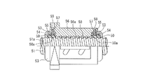
また、図8に第3実施形態を示す。この例では、同図に示すように、本発明に係る潤滑剤供給体として潤滑剤含有ポリマ部材50をシールタイプのボールねじ装置のシール兼潤滑剤供給体としてナット端面に装着したものである。この潤滑剤含有ポリマ部材50についても、上記第一実施形態同様に、母材中の空隙部の割合を、被潤滑部となる、ねじ軸51のねじ溝51aとの接触部から離れるにつれて接触部近傍よりも多くしている。
FIG. 8 shows a third embodiment. In this example, as shown in the figure, a lubricant-containing
この潤滑剤含有ポリマ部材50は、円筒形状を呈しており、その内周面にねじ軸51のねじ溝51aに嵌合する凸部50aを有すると共に、その側面に円筒形状を軸方向に沿って切断する不図示の切割が1箇所設けてある。潤滑剤含有ポリマ部材50の外周面には、ガータスプリング53がはめ込まれる環状溝54が形成されている。更に、環状溝54と干渉しない位置に、円環状の補強部材55が嵌着されている。
The lubricant-containing
この潤滑剤含有ポリマ部材50は、上記切割を開いてリングを拡開させてねじ軸51にはめ合わせた後、ボールねじナット56の端面の凹部57に嵌入され、ナット側面からねじ込んだ取付けねじ58の先端を補強部材55に係合させることにより固定される。切割で拡開して取り付けた潤滑剤含有ポリマ部材50を、ガータスプリング53で弾性的に締め付けることにより、ねじ軸51のねじ溝51aと潤滑剤含有ポリマ部材50の内周の凸部50aとの嵌合隙間がゼロ以下に保たれる。
The lubricant-containing
このような構成により、ねじ軸51の外周面に設けた螺旋状のねじ溝21aと、ボールねじナット56の内周面に設けた螺旋状のねじ溝56aと、その両溝間に装填された複数のボール58との接触面に、潤滑剤含有ポリマ部材50から徐々に滲み出る潤滑剤が自動的に供給されて、摩擦抵抗の増大を抑制するとともに、その潤滑剤がボールねじ自体の潤滑にも寄与する。
With such a configuration, the
1 案内レール
2 スライダ
10 サイドシール
11 潤滑剤含有ポリマ部材(潤滑剤供給体)
20 補強板
41 潤滑剤含有ポリマ部材(潤滑剤供給体)
50 潤滑剤含有ポリマ部材(潤滑剤供給体)
H 被潤滑部
S 接触部
K 空隙部
DESCRIPTION OF SYMBOLS 1
20 Reinforcing
50 Lubricant-containing polymer member (lubricant supplier)
H Lubrication part S Contact part K Gap part
Claims (2)
前記母材中の空隙部の割合を、前記被潤滑部との接触部から離れるにつれて接触部近傍よりも多くしたことを特徴とする潤滑剤供給体。 Lubricant supply body having a contact portion with a portion to be lubricated, a base material made of a resin formed in a porous sponge shape, and a lubricant filled in the porous sponge-like gap portion of the base material Because
The lubricant supply body according to claim 1, wherein the ratio of the void portion in the base material is increased from the vicinity of the contact portion as the distance from the contact portion with the lubricated portion increases.
Priority Applications (1)
| Application Number | Priority Date | Filing Date | Title |
|---|---|---|---|
| JP2011099766A JP5699782B2 (en) | 2011-04-27 | 2011-04-27 | Lubricant supply body |
Applications Claiming Priority (1)
| Application Number | Priority Date | Filing Date | Title |
|---|---|---|---|
| JP2011099766A JP5699782B2 (en) | 2011-04-27 | 2011-04-27 | Lubricant supply body |
Publications (2)
| Publication Number | Publication Date |
|---|---|
| JP2012229366A true JP2012229366A (en) | 2012-11-22 |
| JP5699782B2 JP5699782B2 (en) | 2015-04-15 |
Family
ID=47431192
Family Applications (1)
| Application Number | Title | Priority Date | Filing Date |
|---|---|---|---|
| JP2011099766A Active JP5699782B2 (en) | 2011-04-27 | 2011-04-27 | Lubricant supply body |
Country Status (1)
| Country | Link |
|---|---|
| JP (1) | JP5699782B2 (en) |
Cited By (2)
| Publication number | Priority date | Publication date | Assignee | Title |
|---|---|---|---|---|
| JP2015222112A (en) * | 2014-05-23 | 2015-12-10 | 日本精工株式会社 | Rolling bearing guide device |
| CN109690098A (en) * | 2016-09-05 | 2019-04-26 | 日本精工株式会社 | Linear guides |
Families Citing this family (1)
| Publication number | Priority date | Publication date | Assignee | Title |
|---|---|---|---|---|
| CN106263699B (en) * | 2016-08-22 | 2018-04-06 | 海宁金茂五金有限公司 | Has the Jing Yin slide rail of lubricating function |
Citations (6)
| Publication number | Priority date | Publication date | Assignee | Title |
|---|---|---|---|---|
| JPS62241997A (en) * | 1985-04-05 | 1987-10-22 | ア−ムコ インコ−ポレイテツド | Thermosetting microporous polymer lubricant composition and method for molding the same |
| JPS63172186A (en) * | 1987-01-10 | 1988-07-15 | Sumitomo Electric Ind Ltd | Release agent coating roller |
| JPH0741783A (en) * | 1993-07-30 | 1995-02-10 | Ntn Corp | Rolling bearing filled with solid grease |
| JP2006002016A (en) * | 2004-06-17 | 2006-01-05 | Nachi Fujikoshi Corp | Abrasion resistant sliding film and member with the same film formed |
| JP2006292176A (en) * | 2006-04-24 | 2006-10-26 | Nsk Ltd | Lubricant supply body |
| JP2008196588A (en) * | 2007-02-13 | 2008-08-28 | Ntn Corp | Lubricant supply material and linear motion guide |
-
2011
- 2011-04-27 JP JP2011099766A patent/JP5699782B2/en active Active
Patent Citations (6)
| Publication number | Priority date | Publication date | Assignee | Title |
|---|---|---|---|---|
| JPS62241997A (en) * | 1985-04-05 | 1987-10-22 | ア−ムコ インコ−ポレイテツド | Thermosetting microporous polymer lubricant composition and method for molding the same |
| JPS63172186A (en) * | 1987-01-10 | 1988-07-15 | Sumitomo Electric Ind Ltd | Release agent coating roller |
| JPH0741783A (en) * | 1993-07-30 | 1995-02-10 | Ntn Corp | Rolling bearing filled with solid grease |
| JP2006002016A (en) * | 2004-06-17 | 2006-01-05 | Nachi Fujikoshi Corp | Abrasion resistant sliding film and member with the same film formed |
| JP2006292176A (en) * | 2006-04-24 | 2006-10-26 | Nsk Ltd | Lubricant supply body |
| JP2008196588A (en) * | 2007-02-13 | 2008-08-28 | Ntn Corp | Lubricant supply material and linear motion guide |
Cited By (3)
| Publication number | Priority date | Publication date | Assignee | Title |
|---|---|---|---|---|
| JP2015222112A (en) * | 2014-05-23 | 2015-12-10 | 日本精工株式会社 | Rolling bearing guide device |
| CN109690098A (en) * | 2016-09-05 | 2019-04-26 | 日本精工株式会社 | Linear guides |
| CN109690098B (en) * | 2016-09-05 | 2021-05-14 | 日本精工株式会社 | Linear guide rail |
Also Published As
| Publication number | Publication date |
|---|---|
| JP5699782B2 (en) | 2015-04-15 |
Similar Documents
| Publication | Publication Date | Title |
|---|---|---|
| JP4396375B2 (en) | Ball screw device | |
| JP5615649B2 (en) | Ball bearing | |
| JP2011236998A (en) | Rolling bearing | |
| JP5699782B2 (en) | Lubricant supply body | |
| JP2012163172A (en) | Ball bearing cage and ball bearing | |
| JPH112243A (en) | Lubricant feeding body | |
| KR101909393B1 (en) | Lubricatable ball screw device | |
| JP3648855B2 (en) | Lead screw device | |
| JP5687012B2 (en) | Sealed rolling bearing | |
| JP5872172B2 (en) | Ball bearing cage and ball bearing | |
| JP2008240783A (en) | Lubricant feeding body, and ball screw provided with the same | |
| CN110382890B (en) | Rolling bearing and bearing structure provided with same | |
| CN203756734U (en) | Self-oil-storing micro pump oil lubrication combined angular contact ball bearing and deep groove ball bearing | |
| JP2018035860A (en) | Curve rolling guide unit and method for loading rolling body to slider thereof | |
| CN107269695B (en) | Ball screw | |
| KR102300420B1 (en) | Ball Screw | |
| JP6287503B2 (en) | Roller bearing cage | |
| JP5187185B2 (en) | Rolling support device | |
| JP2014190453A (en) | Angular ball bearing | |
| JP2006292176A (en) | Lubricant supply body | |
| JP2010185516A (en) | Ball screw | |
| JP4725339B2 (en) | Ball screw device | |
| JP2003166550A (en) | Bearing device | |
| JP2017026110A (en) | Lubricant supply body and linear motion device | |
| JP2009079776A (en) | Linear motion rolling guide unit |
Legal Events
| Date | Code | Title | Description |
|---|---|---|---|
| A621 | Written request for application examination |
Free format text: JAPANESE INTERMEDIATE CODE: A621 Effective date: 20140403 |
|
| A977 | Report on retrieval |
Free format text: JAPANESE INTERMEDIATE CODE: A971007 Effective date: 20141016 |
|
| A131 | Notification of reasons for refusal |
Free format text: JAPANESE INTERMEDIATE CODE: A131 Effective date: 20141028 |
|
| A521 | Written amendment |
Free format text: JAPANESE INTERMEDIATE CODE: A523 Effective date: 20141225 |
|
| TRDD | Decision of grant or rejection written | ||
| A01 | Written decision to grant a patent or to grant a registration (utility model) |
Free format text: JAPANESE INTERMEDIATE CODE: A01 Effective date: 20150120 |
|
| A61 | First payment of annual fees (during grant procedure) |
Free format text: JAPANESE INTERMEDIATE CODE: A61 Effective date: 20150202 |
|
| R150 | Certificate of patent or registration of utility model |
Ref document number: 5699782 Country of ref document: JP Free format text: JAPANESE INTERMEDIATE CODE: R150 |