JP2012225035A - Stepladder type workbench - Google Patents
Stepladder type workbench Download PDFInfo
- Publication number
- JP2012225035A JP2012225035A JP2011092706A JP2011092706A JP2012225035A JP 2012225035 A JP2012225035 A JP 2012225035A JP 2011092706 A JP2011092706 A JP 2011092706A JP 2011092706 A JP2011092706 A JP 2011092706A JP 2012225035 A JP2012225035 A JP 2012225035A
- Authority
- JP
- Japan
- Prior art keywords
- handrail frame
- main leg
- top plate
- bracket
- stepladder
- Prior art date
- Legal status (The legal status is an assumption and is not a legal conclusion. Google has not performed a legal analysis and makes no representation as to the accuracy of the status listed.)
- Granted
Links
- 238000004040 coloring Methods 0.000 claims description 16
- 239000003086 colorant Substances 0.000 claims description 2
- 239000002184 metal Substances 0.000 abstract description 3
- 238000004804 winding Methods 0.000 description 4
- 230000002265 prevention Effects 0.000 description 2
- 238000009434 installation Methods 0.000 description 1
- 230000009191 jumping Effects 0.000 description 1
- 238000000034 method Methods 0.000 description 1
Images



Landscapes
- Ladders (AREA)
Abstract
Description
本発明は、高所作業台としての手摺付きの脚立式作業台に関するものである。 The present invention relates to a stepladder-type workbench with a handrail as an aerial workbench.
脚立は、従来、周知のように例えば複数の踏桟を適宜間隔で取付けた梯子状の一対の脚部の上端を回動自在に軸着し、軸着部である最上段の部分に踏板を設け、軸着部を回動することで一対の脚部を開閉すると同時に踏板を折り畳みまたは開いて使用し、または不使用時に収納するようにしたものである。 As is well known in the art, the stepladder is pivotally attached to the upper ends of a pair of ladder-like legs to which a plurality of step bars are attached at appropriate intervals, and a step board is attached to the uppermost part as the shaft attachment part. It is provided to open and close the pair of leg portions by rotating the shaft attachment portion, and at the same time to fold or open the tread plate for use or to store it when not in use.
ところで、踏板は前記のように三角形の2辺に位置する梯子状の脚部の頂点に位置する梯子の最上段に設けられるものであるため、人が立てるだけの狭い面積しか確保できない。さらに、踏板に立った状態では、手摺り等の手掛かりとなるものがないため、不安定な状態で作業することになり、踏板から転落するなどの危険発生のおそれもあり、安全面で問題があった。 By the way, since the tread is provided at the top of the ladder located at the apex of the ladder-like legs located on the two sides of the triangle as described above, it can ensure only a small area that a person can stand. In addition, when standing on the tread, there is no clue such as a handrail, so you will be working in an unstable state, and there is a risk of falling off the tread, which may cause safety problems. there were.
これに対して、本願の発明者は下記特許文献にあるように、踏板の上方に転落防止手段としての手摺を設ける場合、脚部の開閉や踏板の折り畳み・開きの動作に連動して転落防止手段も折り畳まれたり開いたりして使い勝手がよく、不使用時には脚部と一体的になって偏平に折り畳まれ、収納スペースが少なくてすみ、また、使用時には作業者の周囲に配置するから安全性も向上する手摺付き脚立を提案し、出願した。
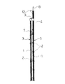
これは図14、図15に示すように、上部に手摺支柱部分4を延設した一対の支柱脚1間に踏桟2を適宜間隔で取付けて梯子状の主脚3を形成し、この主脚3の一対を対向させ、一方の主脚3を長尺に、他方の主脚3をこれよりも多少短尺に形成し、長尺な主脚3の上端よりも多少下方位置に短尺な主脚3の上端を折畳金物9で回動自在に軸着し、支柱脚1の上部位置で主脚3間に作業床用天板6を折畳み自在に掛け渡す。
As shown in FIG. 14 and FIG. 15, a ladder-like
作業床用天板6は、一端が長尺な主脚3に回動自在に軸着され、他端が水平の使用状態で短尺な主脚3よりも外方に突出する幅に形成する。
The work
図中7は、一端が作業床用天板6の下面に回動自在に軸着され、他端が短尺な主脚3に取付けてある踏桟2に回動自在に軸着されるアーム状のステイを示す。
In the figure,
長尺な主脚3の上端に前記作業床用天板6の突出方向と同じ方向に突出する手摺枠8を主脚3内から上下方向に出没自在に取付ける。
A
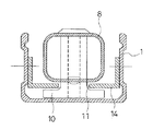
図17に示すように手摺枠8は平面コ字形に形成され、その取付構造としては、コ字形の開口部側の端部外側に案内突起10を設け、一方、図18にも示すように支柱脚1の内部にこの案内突起10がスライドするガイド長孔11を支柱脚1の長さ方向にそって形成した断面コ字形の係合部材14を固定し、支柱脚1の上端は手摺枠8の回動および上下動が可能となるように開口に形成した。
As shown in FIG. 17, the
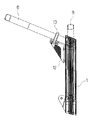
また、支柱脚1の上端側部に手摺枠8を引き出した状態で下方から支承する支持部材12を取付け、この支持部材12に手摺枠8を固定する固定金具13を取付ける。
Further, a
固定金具13は、L字形に形成され、支持部材12に対して上下方向に回動自在に軸着されて上方の回動位置で手摺枠8に被さるように構成される。
The
なお、手摺枠8の突出方向の長さは、突出端部が前記作業床用天板6の突出端部とほぼ同じ位置となるように設定する。また、手摺枠8は、突出状態で先端が僅かに上向きとなるように支持部材12の上面を先端に向けて例えば約7度程度上向きとなるように傾斜させる。
The length of the
次に使用法について説明する。不使用時には図16に示すように長尺な主脚3と短尺な主脚3は折畳金物9を中心軸として平行に折畳まれている。この状態で、ステイ7と作業床用天板6は、一端がそれぞれの主脚3との回動軸着部を介して回動し、長尺な主脚3と短尺な主脚3との間で他端が上方に移動して扁平に折畳まれている。
Next, the usage will be described. When not in use, as shown in FIG. 16, the long
また、固定金具13は下方に回動した状態で支持部材12の上から外れ、手摺枠8は、案内突起10がガイド長孔11にそって下方に移動し、支柱脚1の内部に収納された状態にある。
Further, the
この状態から作業台を使用するには、長尺および短尺な主脚3を折畳金物9を介して図16において左右に回動し全体をハ字状に広げれば、主脚3の広がりに追随して作業床用天板6とステイ7もそれぞれの主脚3との軸着部を中心にして下方に回動し、長尺および短尺な主脚3,3の間で水平位置まで移動する。
In order to use the work table from this state, if the long and short
この水平位置で作業床用天板6は、途中が主脚3に設けてある踏桟2を使用した天板受け材の上に載置し、この天板受け材で下方から支承される。そして、作業床用天板6は、回動軸着部とは反対側の先端が主脚3よりも外方に突出するから、壁面などの作業箇所に近接して作業床用天板6を位置させることができ、作業性の向上が図れる。
In this horizontal position, the work
また、対向する主脚3,3は、一方を長尺に他方を短尺に形成してあるから、上部の回動軸着部が長尺な主脚3の上端に位置せず、これよりも下方位置となるから、長尺な主脚3に短尺な主脚3が寄りかかるような状態となり、対向する主脚を上端で軸着する場合に比較して安定性を増すことができる。
Further, since the opposing
手摺枠8のセットは、支柱脚1の内部に収納されている手摺枠8を支柱脚1にそって上方にスライドさせて引き上げる。手摺枠8の開口端部が支柱脚1の上端まで引き上げられたならば、下端を軸にして手摺枠8を下方の水平方向に回動する。
The set of the
略水平位置で手摺枠8は支柱脚1に取付けてある支持部材12の上に当接し、それ以上の回動が阻止されてこの略水平位置に係止される。次に、固定金具13を上方に回動し、手摺枠8の上に被せるようにすれば、手摺枠8が支持部材12の上、すなわち支柱脚1の上端部に固定される。
At a substantially horizontal position, the
よって、作業中に手摺枠8が外れるおそれがなく、作業の安全を確保できる。また、手摺枠8のセットは、上方への引き出しと、水平方向への回動とで行えるから、作業床用天板6上に載っている作業員の邪魔になることもない。
Therefore, there is no possibility that the
そして、手摺枠8は、主脚1から外方水平方向に突出している作業床用天板6の上方に位置するから、作業床用天板6の突出部分に載って作業する作業員の安全を確保できる。
And since the
前記手摺枠8のセットは、第1に、手摺枠8を支柱脚1にそって上方にスライドさせて引き上げる動作、第2に、支持部材12の上に当接し、略水平位置に係止動作、第3に、固定金具13を上に被せる動作の3段階の動作により、手摺枠8の固定が行われる。
The set of the
このような複数動作の組み合わせでの手摺枠8の固定セットを行うのでは、迅速性に欠け、面倒であり、完全な履行を期待できないおそれもある。
If the
本発明の目的は前記従来例の不都合を解消し、上端を折畳金物で回動自在に軸着して下方に向かって外側に傾斜する一対の梯子状の主脚間に、一端を一方の主脚に回動自在に軸着し、他端を他方の主脚より外方に突出させるように、主脚間に作業床用天板を折り畳み自在に架設し、前記長尺な主脚上端に前記作業床用天板の突出方向と同じ方向に突出する平面コ字形に形成された手摺枠を設けた脚立式作業台において、作業床用天板上に立つ作業員の邪魔にならずに、当該作業員がワンタッチで、迅速かつ簡単に手摺枠を回動して水平の所定位置に固定セットすることができる脚立式作業台を提供するものである。 The object of the present invention is to eliminate the inconvenience of the conventional example, and to pivot between one pair of ladder-shaped main legs with the upper end pivotably supported by a folded metal fitting and inclined outwardly downward. A work floor top plate is foldable between the main legs so that the main legs can pivot on the main legs and the other end protrudes outward from the other main legs. In a stepladder-type worktable provided with a handrail frame formed in a plane U shape projecting in the same direction as the projecting direction of the work floor top plate, it does not interfere with an operator standing on the work floor top plate. In addition, a stepladder-type work table is provided that allows the worker to rotate the handrail frame quickly and easily and fix it at a predetermined horizontal position with one touch.
本発明は前記目的を達成するため、請求項1記載の発明は、手摺枠は、前記長尺な主脚の上端に設けたブラケットに端部を軸着し、このブラケットを介して主脚に沿う折り畳み状態から上方に跳ね上がるようにして、略水平方向に突出するように支承することを要旨とするものである。 In order to achieve the above object, the present invention is characterized in that the handrail frame has an end portion pivotally attached to a bracket provided at an upper end of the elongated main leg, and the main leg is connected to the bracket through the bracket. The gist is to support it so as to protrude in a substantially horizontal direction by jumping upward from the folded state.
請求項1記載の本発明によれば、手摺枠は、ブラケットを介して主脚に沿う折り畳み状態から上方に跳ね上がるようにして略水平方向に突出するように支承されるものであり、ブラケットが手摺枠回動のガイドとなるとともに、手摺枠はブラケットによりワンタッチで固定セットすることができる。 According to the first aspect of the present invention, the handrail frame is supported so as to protrude in a substantially horizontal direction so as to jump upward from the folded state along the main leg via the bracket. While being a guide for frame rotation, the handrail frame can be fixed and set with a single touch of the bracket.
請求項2記載の本発明は、ブラケットは、4分割円周程度の円弧状縁を有する取付片を平行させ、その円弧状縁に沿って手摺枠を主脚に沿う折り畳み状態から上方に跳ね上がるように誘導することを要旨とするものである。
The bracket of the present invention according to
請求項2記載の本発明によれば、前記作用に加えて、ブラケットが手摺枠回動のガイドとなるのに4分割円周程度の円弧状縁に沿って上方に跳ね上がるように誘導できるのでスムーズな動きを得ることができる。 According to the second aspect of the present invention, in addition to the above action, the bracket can be guided so as to jump upward along an arcuate edge having a circumference of about four divisions to become a guide for turning the handrail frame. Movement can be obtained.
請求項3記載の本発明は、ブラケットは、4分割円周程度の円弧状縁を有する取付片を平行させ、その間に手摺枠端部を挿入してなり、このブラケットに第1のピン部材で前記手摺枠端部を回動可能に枢着し、手摺枠にスライド可能に設けた鞘体を取付片の円弧状縁に当接し、この鞘体に設ける第2のピン部材が挿通する手摺枠の貫通孔は第2のピン部材が移動し得るよう長孔に形成され、第1のピン部材と第2のピン部材の間を縮小するようにバネで付勢し、前記取付片の円弧状縁にはこの第2のピン部材が嵌り込む切り欠きを適宜位置に形成したことを要旨とするものである。 According to the third aspect of the present invention, the bracket is formed by paralleling mounting pieces having arcuate edges of approximately four divided circumferences, and inserting a handrail frame end portion therebetween, and the bracket is provided with a first pin member. A handrail frame in which the end of the handrail frame is pivotally attached, a sheath body slidably provided on the handrail frame is brought into contact with the arcuate edge of the attachment piece, and a second pin member provided in the sheath body is inserted. The through hole is formed as a long hole so that the second pin member can move, and is biased by a spring so as to reduce the space between the first pin member and the second pin member, and the mounting piece has an arc shape. The gist is that a notch into which the second pin member is fitted is formed at an appropriate position on the edge.
請求項3記載の本発明によれば、手摺枠には第2のピン部材を有する鞘体が設けられており、この鞘体を手摺枠に対してスライドさせることで第2のピン部材も移動する。鞘体を手で持って手摺枠を上方に跳ね上げるようにするが、その際に、鞘体を手摺枠に対してスライドさせて第2のピン部材を取付片の円弧状縁に設けた切り欠きから外すことでロックを解除でき、第2のピン部材はそのまま取付片の円弧状縁に当たりながら手摺枠とともに移動し、手摺枠が略水平になった状態で第2のピン部材は自動的に取付片の円弧状縁に設けた切り欠きに入り込みロックが行われる。 According to the third aspect of the present invention, the handrail frame is provided with the sheath body having the second pin member, and the second pin member is also moved by sliding the sheath body with respect to the handrail frame. To do. Hold the sheath body by hand and flip the handrail frame upward. At this time, the sheath body is slid relative to the handrail frame and the second pin member is provided on the arcuate edge of the mounting piece. The lock can be released by removing it from the notch, and the second pin member moves with the handrail frame as it hits the arcuate edge of the mounting piece, and the second pin member automatically moves in a state where the handrail frame is substantially horizontal. Locking is performed by entering a notch provided in the arcuate edge of the mounting piece.
請求項4記載の発明は、鞘体は上床板に窓孔を形成し、手摺枠端部に設ける着色注意部をこの窓孔から顕出させることを要旨とするものである。
The gist of the invention described in
請求項4記載の発明によれば、鞘体の上床板に形成した窓孔から手摺枠端部に設ける着色注意部を観取することができ、鞘体の第2のピン部材のロック状態を知ることができる。
According to the invention of
請求項5記載の発明は、前記窓孔は矢印形状であり、一方、着色注意部は2色に分け、その一つは赤系統色で、いずれの色も一色のみ窓孔から顕出させることが可能なことを要旨とするものである。 According to a fifth aspect of the present invention, the window hole has an arrow shape, while the coloring attention part is divided into two colors, one of which is a red color, and only one color is exposed from the window hole. The gist is that this is possible.
請求項5記載の発明によれば、前記請求項4の鞘体の上床板に形成した窓孔から手摺枠端部に設ける着色注意部を観取することができ、鞘体の第2のピン部材のロック状態を知ることができるということに関して、矢印形状の窓孔には赤系統色が現れた時はロックがなされていないことが分かり、確実にロックを行って手摺枠を設置し、安全性を高めることができる。 According to the fifth aspect of the present invention, it is possible to observe the colored caution part provided at the end of the handrail frame from the window hole formed in the upper floor plate of the scabbard according to the fourth aspect. With regard to being able to know the locked state of the member, when the red system color appears in the arrow-shaped window hole, it is known that the lock has not been made, and the handrail frame is securely installed and the handrail frame is installed. Can increase the sex.
以上述べたように本発明の脚立式作業台は、上端を折畳金物で回動自在に軸着して下方に向かって外側に傾斜する一対の梯子状の主脚間に、一端を一方の主脚に回動自在に軸着し、他端を他方の主脚より外方に突出させるように、主脚間に作業床用天板を折り畳み自在に架設し、前記長尺な主脚上端に前記作業床用天板の突出方向と同じ方向に突出する平面コ字形に形成された手摺枠を設けた脚立式作業台において、作業床用天板上に立つ作業員の邪魔にならずに、当該作業員がワンタッチで、迅速かつ簡単に手摺枠を回動して水平の所定位置に固定セットすることができるものである。 As described above, the stepladder-type workbench of the present invention has one end between a pair of ladder-shaped main legs that are pivotally attached to the upper end by a folding hardware and inclined outward. A work floor top plate is foldably installed between the main legs so that the other main leg can be pivotally attached to the main leg and the other end protrudes outward from the other main leg. In a stepladder-type work table provided with a handrail frame formed in a plane U-shape projecting in the same direction as the projecting direction of the work floor top plate at the upper end, if it interferes with a worker standing on the work floor top plate In addition, the worker can rotate the handrail frame quickly and easily and fix it at a predetermined horizontal position with one touch.
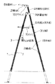
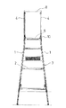
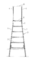
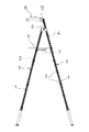
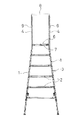
以下、図面について本発明の実施の形態を詳細に説明する。図1〜図4は本発明の脚立式作業台の全体の概要を示すもので、前記従来例を示す図14〜16と同一構成要素には同一参照符号を付したものである。 Hereinafter, embodiments of the present invention will be described in detail with reference to the drawings. 1 to 4 show an outline of the entire stepladder-type workbench according to the present invention, and the same components as those in FIGS. 14 to 16 showing the conventional example are given the same reference numerals.
上部に手摺支柱部分4を延設した一対の支柱脚1間に踏桟2を適宜間隔で取付けて梯子状の主脚3を形成した。
Ladder-shaped
主脚3の一対を対向させ、一方の主脚3を長尺に、他方の主脚3をこれよりも多少短尺に形成し、長尺な主脚3の上端よりも多少下方位置に短尺な主脚3の上端を折畳金物9で回動自在に軸着した。このようにして、折畳金物9により、一対の主脚3は、それぞれ開き体となる。
A pair of
かかる支柱脚1の上部位置で主脚3間に作業床用天板6を折畳み自在に掛け渡す。作業床用天板6は、一端が長尺な主脚3に回動自在に軸着され、他端が水平の使用状態で短尺な主脚3よりも外方に突出する幅に形成する。図中7は、一端が作業床用天板6の下面に回動自在に軸着され、他端が短尺な主脚3に取付けてある踏桟2に回動自在に軸着されるアーム状のステイを示す。
The work
長尺な主脚3の上端に前記作業床用天板6の突出方向と同じ方向に突出する手摺枠8を、長尺な主脚3に添うように収まる状態から水平よりもわずかに、例えば約7度程度上向きとなるように傾斜させる状態まで跳ねあがるように出没自在に取付ける。
A
本発明は、手摺枠8を、長尺な主脚3の上端に取付けるのに、ブラケット16を介在させ、このブラケット16を介して長尺な主脚3に沿う折り畳み状態から上方に跳ね上がるようにして、略水平方向に突出するように支承するものとした。
In the present invention, the
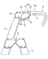
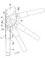
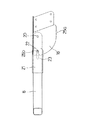
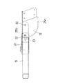
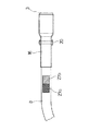
該ブラケット16は、図5〜図8に示すように、4分割円周程度の円弧状縁17を下向きにして有する取付片18を平行させ、その円弧状縁17に沿って手摺枠8を主脚3に沿う折り畳み状態から上方に跳ね上がるように誘導するものである。
As shown in FIGS. 5 to 8, the
平行する取付片18の端には主脚3の上端への係合片19を一体に連続形成し、この係合片19で主脚3を挟み込みビス止めすることで、ブラケット16を主脚3の上端へ取付ける。
An engaging
手摺枠8は平行する取付片18間に端部を挿入してなり、このブラケット16に第1のピン部材20で回動可能に枢着した。
An end portion of the
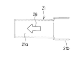
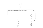
さらに、この手摺枠8には矩形断面の角管を本体21aとする鞘体21をスライド自在に嵌め、該鞘体21の本体21aの端部に形成する二股片21bに架け渡す第2のピン部材22を手摺枠8に形成した横長孔23の貫通孔に挿通させる。
Further, the
前記第1のピン部材20と第2のピン部材22間に巻きバネ24を架設して、この巻きバネ24で第1のピン部材20と第2のピン部材22の間を縮小するように付勢した。
A winding
このようにして、鞘体21は第2のピン部材22をもってブラケット16の取付片18の円弧状縁17に当接し、一方、前記取付片18の円弧状縁17にはこの第2のピン部材22が嵌り込む切り欠き25a、25bを形成した。
In this way, the
切り欠き25a、25bのうち、切り欠き25aは切り欠き25bよりも小さなものでよく、手摺枠8が長尺な主脚3に添うように収まる状態で第2のピン部材22が嵌り込む位置に形成する。
Of the
切り欠き25bは切り欠き25aよりも深く形成することで確実なロックが得られるもので、手摺枠8が前記折り畳み状態から上方に跳ね上がるようにして、略水平方向に突出する状態で第2のピン部材22が嵌り込む位置に形成する。
The
図10〜図13に示すように、鞘体21は角管である本体21aの上床板に矢印形状の窓孔26を形成し、これに対応して手摺枠8の端部に着色注意部として赤系統色の着色注意部27aと緑系統色の着色注意部27bとを連続させて設け、これら赤系統色の着色注意部27aと緑系統色の着色注意部27bとが第2のピン部材22が切り欠き25bに嵌り込む前と後とで、それぞれ一色のみ窓孔26から顕出させるようにした。
As shown in FIGS. 10 to 13, the
図1中、15は開き体である一対の主脚3のうち、長尺な主脚3に軸着ピンによる回動軸着部を介して軸支される開き止め金具で、先端部に他方の開き体である短尺な主脚3に設けた係止ピンに係合する切り欠き溝を形成した横長片からなる。
In FIG. 1,
次に使用法について説明する。不使用時には図4に示すように長尺な主脚3と短尺な主脚3は折畳金物9を中心軸として平行に折畳まれている。
Next, the usage will be described. When not in use, as shown in FIG. 4, the long
この状態から作業台を使用するには、長尺および短尺な主脚3を折畳金物9を介して図1に示すように左右に回動し全体をハ字状に広げれば、主脚3の広がりに追随して天板6とステイ7もそれぞれの主脚3との軸着部を中心にして下方に回動し、長尺および短尺な主脚3,3の間で水平位置まで移動する。
In order to use the work table from this state, if the long and short
この水平位置で作業床用天板6は、途中が主脚3に設けてある踏桟2を使用した天板受け材の上に載置し、この天板受け材で下方から支承される。そして、作業床用天板6は、回動軸着部とは反対側の先端が主脚3よりも外方に突出するから、壁面などの作業箇所に近接して作業床用天板6を位置させることができ、作業性の向上が図れる。
In this horizontal position, the work
また、対向する主脚3,3は、一方を長尺に他方を短尺に形成してあるから、上部の回動軸着部が長尺な主脚3の上端に位置せず、これよりも下方位置となるから、長尺な主脚3に短尺な主脚3が寄りかかるような状態となり、対向する主脚を上端で軸着する場合に比較して安定性を増すことができる。
Further, since the opposing
次に手摺枠8をセットする方法を説明する。手摺枠8は長尺な主脚3に添うように収まっており、第2のピン部材22が切り欠き25aに嵌り込んでロックされている。
Next, a method for setting the
この状態で、鞘体21部分もしくは手摺枠8の他の部分を手で掴んで、この手摺枠8を跳ね上げるようにすれば、第2のピン部材22が切り欠き25aから自動的に抜け出て(鞘体21をスライドさせる必要はない)、ブラケット16の取付片18の円弧状縁17に当接ながらすべり、手摺枠8が略水平方向に突出する状態になったところで、巻きバネ24が縮んで第2のピン部材22が切り欠き25bに嵌り込みロックが行われる。
In this state, if the
鞘体21の窓孔26では、赤系統色の着色注意部27aの顕出から緑系統色の着色注意部27bの顕出へと色が変わり、確実にロックされたことを表示する。
In the
よって、作業中に手摺枠8が外れるおそれがなく、作業の安全を確保できる。また、手摺枠8のセットは、上方への回動のみでワンタッチで行え、しかも、作業床用天板6上に載っている作業員の邪魔になることもない。
Therefore, there is no possibility that the
そして、手摺枠8は、主脚1から外方水平方向に突出している作業床用天板6の上方に位置するから、作業床用天板6の突出部分に載って作業する作業員の安全を確保できる。
And since the
一方、使用後に手摺枠8を畳むには、鞘体21を窓孔26が示す矢印方向にスライドさせれば、巻きバネ24が伸び、第2のピン部材22が切り欠き25bから抜け出るので、そのまま手摺枠8を押し下げれば、第2のピン部材22がブラケット16の取付片18の円弧状縁17に当接ながらすべり、手摺枠8が長尺な主脚3に添うように収まるところで第2のピン部材22が切り欠き25aに嵌り込んで軽くロックさる。
On the other hand, in order to fold the
この時、鞘体21の窓孔26では、緑系統色の着色注意部27bの顕出から赤系統色の着色注意部27aの顕出へと色が変わり、ロックが行われていないことを表示する。
At this time, in the
1 支柱脚 2 踏桟
3 主脚 4 手摺支柱部分
5 手摺 6 作業床用天板
7 ステイ 8 手摺枠
9 折畳金物 10 案内突起
11 ガイド長孔 12 支持部材
13 固定金具 14 係合部材
15 開き止め金具 16 ブラケット
17 円弧状縁 18 取付片
19 係合片 20 第1のピン部材
21 鞘体 21a 本体
21b 二股片 22 第2のピン部材
23 横長孔 24 巻きバネ
25a、25b 切り欠き 26 窓孔
27a 赤系統色の着色注意部
27b 緑系統色の着色注意部
DESCRIPTION OF
Claims (5)
前記手摺枠は、前記長尺な主脚の上端に設けたブラケットに端部を軸着し、このブラケットを介して主脚に沿う折り畳み状態から上方に跳ね上がるようにして、略水平方向に突出するように支承することを特徴とする脚立式作業台。 One end is pivotally attached to one main leg, and the other end is pivotally attached between a pair of ladder-shaped main legs that are pivotally attached to the upper end with folding hardware and tilted outward. The work floor top plate is foldable between the main legs so that it protrudes outward from the other main leg, and the upper end of the long main leg is in the same direction as the protrusion direction of the work floor top plate. In the stepladder-type work table provided with a handrail frame formed in a protruding planar U shape,
The handrail frame projects in a substantially horizontal direction so that the end is pivotally attached to a bracket provided at the upper end of the long main leg and the upper hand jumps upward from the folded state along the main leg via the bracket. A stepladder-type workbench characterized by being supported in the manner described above.
Priority Applications (1)
| Application Number | Priority Date | Filing Date | Title |
|---|---|---|---|
| JP2011092706A JP5837757B2 (en) | 2011-04-19 | 2011-04-19 | Stepladder platform |
Applications Claiming Priority (1)
| Application Number | Priority Date | Filing Date | Title |
|---|---|---|---|
| JP2011092706A JP5837757B2 (en) | 2011-04-19 | 2011-04-19 | Stepladder platform |
Publications (2)
| Publication Number | Publication Date |
|---|---|
| JP2012225035A true JP2012225035A (en) | 2012-11-15 |
| JP5837757B2 JP5837757B2 (en) | 2015-12-24 |
Family
ID=47275509
Family Applications (1)
| Application Number | Title | Priority Date | Filing Date |
|---|---|---|---|
| JP2011092706A Active JP5837757B2 (en) | 2011-04-19 | 2011-04-19 | Stepladder platform |
Country Status (1)
| Country | Link |
|---|---|
| JP (1) | JP5837757B2 (en) |
Cited By (7)
| Publication number | Priority date | Publication date | Assignee | Title |
|---|---|---|---|---|
| JP2015031103A (en) * | 2013-08-06 | 2015-02-16 | アルインコ株式会社 | Stepladder platform |
| JP2015067980A (en) * | 2013-09-27 | 2015-04-13 | アルインコ株式会社 | Stepladder system workbench |
| JP2017031659A (en) * | 2015-07-31 | 2017-02-09 | ジー・オー・ピー株式会社 | Stepladder type working platform |
| JP2018193738A (en) * | 2017-05-16 | 2018-12-06 | ジー・オー・ピー株式会社 | Workbench |
| JP2019019643A (en) * | 2017-07-21 | 2019-02-07 | ジー・オー・ピー株式会社 | Workbench |
| JP2020112001A (en) * | 2019-01-16 | 2020-07-27 | 特殊梯子製作所有限会社 | Ladder with handrail |
| JP2020144187A (en) * | 2019-03-05 | 2020-09-10 | 株式会社リコー | Support device and stand display |
Citations (7)
| Publication number | Priority date | Publication date | Assignee | Title |
|---|---|---|---|---|
| JPS59100U (en) * | 1982-06-19 | 1984-01-05 | 梶浦 春夫 | Stepladder with handrail |
| JPS6153500U (en) * | 1984-09-12 | 1986-04-10 | ||
| JP2002138783A (en) * | 2000-11-07 | 2002-05-17 | Gop Kk | Step ladder having handrail |
| JP2005290763A (en) * | 2004-03-31 | 2005-10-20 | Gop Kk | Handrail member for portable work bench |
| JP2006152593A (en) * | 2004-11-26 | 2006-06-15 | Gop Kk | Portable worktable |
| JP2008255586A (en) * | 2007-04-02 | 2008-10-23 | Gop Kk | Handrail member of portable working platform |
| JP2010126968A (en) * | 2008-11-27 | 2010-06-10 | Gop Kk | Portable workbench |
-
2011
- 2011-04-19 JP JP2011092706A patent/JP5837757B2/en active Active
Patent Citations (7)
| Publication number | Priority date | Publication date | Assignee | Title |
|---|---|---|---|---|
| JPS59100U (en) * | 1982-06-19 | 1984-01-05 | 梶浦 春夫 | Stepladder with handrail |
| JPS6153500U (en) * | 1984-09-12 | 1986-04-10 | ||
| JP2002138783A (en) * | 2000-11-07 | 2002-05-17 | Gop Kk | Step ladder having handrail |
| JP2005290763A (en) * | 2004-03-31 | 2005-10-20 | Gop Kk | Handrail member for portable work bench |
| JP2006152593A (en) * | 2004-11-26 | 2006-06-15 | Gop Kk | Portable worktable |
| JP2008255586A (en) * | 2007-04-02 | 2008-10-23 | Gop Kk | Handrail member of portable working platform |
| JP2010126968A (en) * | 2008-11-27 | 2010-06-10 | Gop Kk | Portable workbench |
Cited By (9)
| Publication number | Priority date | Publication date | Assignee | Title |
|---|---|---|---|---|
| JP2015031103A (en) * | 2013-08-06 | 2015-02-16 | アルインコ株式会社 | Stepladder platform |
| JP2015067980A (en) * | 2013-09-27 | 2015-04-13 | アルインコ株式会社 | Stepladder system workbench |
| JP2017031659A (en) * | 2015-07-31 | 2017-02-09 | ジー・オー・ピー株式会社 | Stepladder type working platform |
| JP2018193738A (en) * | 2017-05-16 | 2018-12-06 | ジー・オー・ピー株式会社 | Workbench |
| JP7074310B2 (en) | 2017-05-16 | 2022-05-24 | ジー・オー・ピー株式会社 | Workbench |
| JP2019019643A (en) * | 2017-07-21 | 2019-02-07 | ジー・オー・ピー株式会社 | Workbench |
| JP2020112001A (en) * | 2019-01-16 | 2020-07-27 | 特殊梯子製作所有限会社 | Ladder with handrail |
| JP2020144187A (en) * | 2019-03-05 | 2020-09-10 | 株式会社リコー | Support device and stand display |
| JP7180453B2 (en) | 2019-03-05 | 2022-11-30 | 株式会社リコー | Support device and stand display |
Also Published As
| Publication number | Publication date |
|---|---|
| JP5837757B2 (en) | 2015-12-24 |
Similar Documents
| Publication | Publication Date | Title |
|---|---|---|
| JP5837757B2 (en) | Stepladder platform | |
| JP5364241B2 (en) | Handrail for portable worktable | |
| KR20060071681A (en) | Folding work bench | |
| RU2008124808A (en) | FOLDING PLATFORM | |
| JP3581957B2 (en) | Workbench | |
| JP5594954B2 (en) | Portable worktable | |
| JP5066026B2 (en) | Telescopic locking mechanism | |
| JP4843381B2 (en) | Portable worktable and handrail member | |
| JP6645766B2 (en) | Stepladder work table | |
| JP3180629U (en) | Stepladder platform | |
| JP6634238B2 (en) | Outrigger type leg device | |
| JP2009235868A (en) | Work bench | |
| JP2013199824A (en) | Ladder fixing device | |
| JP5777695B2 (en) | Portable worktable | |
| JP6254847B2 (en) | Stepladder platform | |
| KR102403398B1 (en) | Foldable safety railing for ladder type work table | |
| JP4814290B2 (en) | ladder | |
| JP3396667B2 (en) | Stepladder with handrails | |
| JP2009024478A (en) | Portable workbench | |
| KR200461587Y1 (en) | safety bar assembly of work table | |
| JP5197325B2 (en) | Portable worktable | |
| KR101426132B1 (en) | A leg foldable bench having the convenience in keeping | |
| JP5628635B2 (en) | Work scaffolding base and cue rod holding bracket for scaffolding base | |
| JP2016044506A (en) | Scaffolding base leg locking device | |
| KR101390859B1 (en) | Fixing device for ladder |
Legal Events
| Date | Code | Title | Description |
|---|---|---|---|
| A621 | Written request for application examination |
Free format text: JAPANESE INTERMEDIATE CODE: A621 Effective date: 20140207 |
|
| A977 | Report on retrieval |
Free format text: JAPANESE INTERMEDIATE CODE: A971007 Effective date: 20141217 |
|
| A131 | Notification of reasons for refusal |
Free format text: JAPANESE INTERMEDIATE CODE: A131 Effective date: 20150217 |
|
| A521 | Request for written amendment filed |
Free format text: JAPANESE INTERMEDIATE CODE: A523 Effective date: 20150413 |
|
| TRDD | Decision of grant or rejection written | ||
| A01 | Written decision to grant a patent or to grant a registration (utility model) |
Free format text: JAPANESE INTERMEDIATE CODE: A01 Effective date: 20151013 |
|
| A61 | First payment of annual fees (during grant procedure) |
Free format text: JAPANESE INTERMEDIATE CODE: A61 Effective date: 20151106 |
|
| R150 | Certificate of patent or registration of utility model |
Ref document number: 5837757 Country of ref document: JP Free format text: JAPANESE INTERMEDIATE CODE: R150 |
|
| R250 | Receipt of annual fees |
Free format text: JAPANESE INTERMEDIATE CODE: R250 |
|
| R250 | Receipt of annual fees |
Free format text: JAPANESE INTERMEDIATE CODE: R250 |