JP2012223402A - Spike for shoe - Google Patents
Spike for shoe Download PDFInfo
- Publication number
- JP2012223402A JP2012223402A JP2011094310A JP2011094310A JP2012223402A JP 2012223402 A JP2012223402 A JP 2012223402A JP 2011094310 A JP2011094310 A JP 2011094310A JP 2011094310 A JP2011094310 A JP 2011094310A JP 2012223402 A JP2012223402 A JP 2012223402A
- Authority
- JP
- Japan
- Prior art keywords
- wear
- resistant
- lateral
- vertical
- plate portion
- Prior art date
- Legal status (The legal status is an assumption and is not a legal conclusion. Google has not performed a legal analysis and makes no representation as to the accuracy of the status listed.)
- Granted
Links
- 210000000078 claw Anatomy 0.000 claims description 42
- 238000005219 brazing Methods 0.000 claims description 12
- 230000004048 modification Effects 0.000 abstract description 3
- 238000012986 modification Methods 0.000 abstract description 3
- 230000000630 rising effect Effects 0.000 abstract description 2
- 238000000034 method Methods 0.000 description 12
- 238000003466 welding Methods 0.000 description 12
- RYGMFSIKBFXOCR-UHFFFAOYSA-N Copper Chemical compound [Cu] RYGMFSIKBFXOCR-UHFFFAOYSA-N 0.000 description 5
- 229910052802 copper Inorganic materials 0.000 description 5
- 239000010949 copper Substances 0.000 description 5
- 238000005304 joining Methods 0.000 description 4
- 239000007769 metal material Substances 0.000 description 4
- 230000035699 permeability Effects 0.000 description 4
- UONOETXJSWQNOL-UHFFFAOYSA-N tungsten carbide Chemical compound [W+]#[C-] UONOETXJSWQNOL-UHFFFAOYSA-N 0.000 description 4
- 229910000975 Carbon steel Inorganic materials 0.000 description 3
- 239000010962 carbon steel Substances 0.000 description 3
- OKTJSMMVPCPJKN-UHFFFAOYSA-N Carbon Chemical compound [C] OKTJSMMVPCPJKN-UHFFFAOYSA-N 0.000 description 2
- KDLHZDBZIXYQEI-UHFFFAOYSA-N Palladium Chemical compound [Pd] KDLHZDBZIXYQEI-UHFFFAOYSA-N 0.000 description 2
- 229910000831 Steel Inorganic materials 0.000 description 2
- 229910001315 Tool steel Inorganic materials 0.000 description 2
- 238000005452 bending Methods 0.000 description 2
- 230000005540 biological transmission Effects 0.000 description 2
- 229910052799 carbon Inorganic materials 0.000 description 2
- 239000000463 material Substances 0.000 description 2
- 229910052751 metal Inorganic materials 0.000 description 2
- 239000002184 metal Substances 0.000 description 2
- 150000002739 metals Chemical class 0.000 description 2
- 239000010959 steel Substances 0.000 description 2
- WFKWXMTUELFFGS-UHFFFAOYSA-N tungsten Chemical compound [W] WFKWXMTUELFFGS-UHFFFAOYSA-N 0.000 description 2
- 229910052721 tungsten Inorganic materials 0.000 description 2
- 239000010937 tungsten Substances 0.000 description 2
- BQCADISMDOOEFD-UHFFFAOYSA-N Silver Chemical compound [Ag] BQCADISMDOOEFD-UHFFFAOYSA-N 0.000 description 1
- 238000005299 abrasion Methods 0.000 description 1
- 229910045601 alloy Inorganic materials 0.000 description 1
- 239000000956 alloy Substances 0.000 description 1
- 239000002131 composite material Substances 0.000 description 1
- 238000009792 diffusion process Methods 0.000 description 1
- 238000010894 electron beam technology Methods 0.000 description 1
- PCHJSUWPFVWCPO-UHFFFAOYSA-N gold Chemical compound [Au] PCHJSUWPFVWCPO-UHFFFAOYSA-N 0.000 description 1
- 229910052737 gold Inorganic materials 0.000 description 1
- 239000010931 gold Substances 0.000 description 1
- 229910052742 iron Inorganic materials 0.000 description 1
- 150000001247 metal acetylides Chemical class 0.000 description 1
- 238000000465 moulding Methods 0.000 description 1
- 229910052763 palladium Inorganic materials 0.000 description 1
- 230000001737 promoting effect Effects 0.000 description 1
- 238000004080 punching Methods 0.000 description 1
- 238000010791 quenching Methods 0.000 description 1
- 230000000171 quenching effect Effects 0.000 description 1
- 230000003014 reinforcing effect Effects 0.000 description 1
- 229920005989 resin Polymers 0.000 description 1
- 239000011347 resin Substances 0.000 description 1
- 229910052709 silver Inorganic materials 0.000 description 1
- 239000004332 silver Substances 0.000 description 1
- 229920003002 synthetic resin Polymers 0.000 description 1
- 239000000057 synthetic resin Substances 0.000 description 1
- 238000002834 transmittance Methods 0.000 description 1
Images


Landscapes
- Footwear And Its Accessory, Manufacturing Method And Apparatuses (AREA)
Abstract
Description
本発明は、地面に対するグリップ性及び競技能力の向上を図るために用いられる靴用スパイクで、特に、靴底に取付け可能な取付け基部に連設された爪板部の耐摩耗を高めた靴用スパイクに関する。 The present invention relates to a shoe spike used for improving the grip performance and competition ability with respect to the ground, and in particular for a shoe having improved wear resistance of a nail plate portion connected to an attachment base portion that can be attached to a shoe sole. Regarding spikes.
靴用スパイクの爪板部の耐摩耗を改善する方法として、従来では、例えば、下記特許文献1に示すように、炭素鋼製の爪板部の先端の角部側部位に、爪板部よりも硬度の大きなタングステン鋼製の耐摩耗性部材を、爪板部の先端及び側辺と面一に連続する状態で当該爪板部の先端に沿って溶接等で一体に接合したもの、或いは、下記特許文献2又は3に示すように、炭素鋼製の爪板部の先端に、当該先端の横幅と同一寸法の棒状に構成された爪板部よりも硬度の大きなタングステン鋼製の耐摩耗性部材を、溶接等で一体に接合したものが提案されている。
As a method for improving the wear resistance of the nail plate portion of the spike for shoes, conventionally, as shown in
従来の靴用スパイクでは、爪板部の先端の角部側部位又は爪板部の先端全域に設けた耐摩耗性部材によって爪板部の先端での摩耗を抑制しているが、例えば、野球の打撃動作、投球動作、ランニング動作、守備動作など競技者の他種多様な動作によって、爪板部の接地時や蹴り出し時等において、爪板部の先端のみならず表裏面や左右の側辺にも各種方向の外力が作用する。 In conventional shoe spikes, wear at the tip of the nail plate is suppressed by a wear-resistant member provided at the corner side portion of the tip of the nail plate or the entire tip of the nail plate. When hitting the nail plate or kicking it out, not only the tip of the nail plate, but also the front and back, left and right sides External forces in various directions also act on the sides.
そのため、前記爪板部の側辺のうち、地面との接触頻度の高い耐摩耗性部材の横方向端面の上方近傍箇所において摩耗が発生し、その摩耗が耐摩耗性部材の上面に沿って爪板部の横方向中央部側に喰い込み進行すると、爪板部の折損や耐摩耗性部材の脱落を招来する問題があった。 Therefore, wear occurs in the vicinity of the upper side of the lateral end surface of the wear-resistant member having a high frequency of contact with the ground, on the side of the claw plate portion, and the wear is clawed along the upper surface of the wear-resistant member. When the bite advances toward the laterally central portion of the plate portion, there is a problem that the nail plate portion is broken or the wear-resistant member is dropped.
本発明は、上述の実状に鑑みて為されたものであって、その主たる課題は、前記耐摩耗性部材の合理的な改造をもって、爪板部の側辺での摩耗進行に起因する折損や耐摩耗性部材の脱落を抑制して、長期にわたって確実・良好なスパイク機能を発揮させることのできる靴用スパイクを提供する点にある。 The present invention has been made in view of the above-mentioned actual situation, and the main problem is that with a reasonable modification of the wear-resistant member, breakage due to wear progress on the side of the nail plate portion or The point is to provide a spike for a shoe that can prevent the wear-resistant member from falling off and can exhibit a reliable and good spike function over a long period of time.
本発明による第1の特徴構成は、靴底に取付け可能な取付け基部に連設された爪板部の先端側に、当該爪板部よりも硬度の大きな耐摩耗性部材が接合されている靴用スパイクであって、
前記耐摩耗性部材が、少なくとも爪板部の先端の角部側において横方向に沿う横向き耐摩耗部と、当該横向き耐摩耗部の角部側の上面から爪板部の側辺に沿って立ち上がる縦向き耐摩耗部とから構成されている点にある。
A first characteristic configuration according to the present invention is a shoe in which a wear-resistant member having a hardness higher than that of the nail plate portion is joined to a tip end side of the nail plate portion continuously provided on an attachment base portion that can be attached to the shoe sole. Spikes for
The wear-resistant member rises along a lateral side of the claw plate part from a lateral wear-resistant part extending along the lateral direction at least at the corner side of the tip of the claw plate part, and an upper surface on the corner part side of the lateral wear-resistant part. It is in the point comprised from the vertical wear-resistant part.
上記構成によれば、前記爪板部の先端には、少なくとも爪板部の先端の角部側において横方向に沿う耐摩耗性部材の横向き耐摩耗部が存在し、前記爪板部の側辺には、横向き耐摩耗部の角部側の上面から爪板部の側辺に沿って立ち上がる耐摩耗性部材の縦向き耐摩耗部が存在するから、爪板部の先端での摩耗を抑制することができるとともに、爪板部の側辺のうち、地面との接触頻度の高い横向き耐摩耗部の横方向端面の上方近傍箇所における摩耗も抑制することができる。 According to the above configuration, at the tip of the nail plate portion, there is a lateral wear-resistant portion of the wear-resistant member along the horizontal direction at least on the corner portion side of the nail plate portion, and the side edge of the nail plate portion Since there is a vertical wear-resistant portion of the wear-resistant member that rises along the side of the nail plate portion from the upper surface on the corner side of the horizontal wear-resistant portion, it suppresses wear at the tip of the nail plate portion. In addition, it is possible to suppress wear in the vicinity of the upper side of the lateral end face of the lateral wear-resistant portion having a high frequency of contact with the ground among the side edges of the nail plate portion.
しかも、前記横向き耐摩耗部の角部側の上面から爪板部の側辺に沿って立ち上がる縦向き耐摩耗部によって爪板部の縦方向での剛性が増し、当該爪板部の撓みによる地面蹴り時の力の伝達ロスを抑止することができる。 In addition, the vertical wear-resistant portion that rises from the upper surface on the corner side of the lateral wear-resistant portion along the side of the nail plate portion increases the rigidity in the vertical direction of the nail plate portion, and the ground due to the deflection of the nail plate portion. Force transmission loss during kicking can be suppressed.
したがって、前記耐摩耗性部材を爪板部の先端に沿う横向き耐摩耗部と爪板部の側辺に沿う縦向き耐摩耗部とから構成するといった合理的な改造をもって、爪板部の側辺での摩耗進行に起因する折損や耐摩耗性部材の脱落を抑制して、長期にわたって確実・良好なスパイク機能を発揮させることができる。 Accordingly, the side of the nail plate portion is rationally modified with the wear-resistant member comprising a lateral wear-resistant portion along the tip of the nail plate portion and a vertical wear-resistant portion along the side of the nail plate portion. It is possible to suppress the breakage due to the progress of wear and the drop-off of the wear-resistant member, and to exhibit a reliable and good spike function over a long period of time.
本発明による第2の特徴構成は、前記横向き耐摩耗部が爪板部の先端における横方向の全域に形成され、前記縦向き耐摩耗部が、横向き耐摩耗部の両角部側の上面に夫々連設され、前記横向き耐摩耗部と両縦向き耐摩耗部とが正面視において上向きコの字状に形成されている点にある。 According to a second characteristic configuration of the present invention, the lateral wear-resistant portion is formed in the entire region in the lateral direction at the tip of the claw plate portion, and the vertical wear-resistant portion is respectively formed on the upper surfaces of both corners of the lateral wear-resistant portion. The horizontal wear resistant part and the vertical wear resistant part are formed in an upward U-shape when viewed from the front.
上記構成によれば、前記爪板部の先端における一方の角部側部位又は両角部側部位にのみ横向き耐摩耗部が存在する場合に比して、爪板部の先端全域及び両側辺での摩耗を良好に抑制することができるとともに、上向きコの字状の耐摩耗性部材と爪板部との接合面積の増大によって接合力が強化されるから、爪板部の接地時や蹴り出し時等において大きな外力が作用しても、耐摩耗性部材の脱落を良好に抑制することができる。 According to the above configuration, compared to the case where a lateral wear-resistant portion exists only at one corner side portion or both corner side portions at the tip of the nail plate portion, the tip end region of the nail plate portion and both sides are Wear can be suppressed well, and the bonding force is strengthened by increasing the bonding area between the upward U-shaped wear-resistant member and the nail plate, so when the nail plate is grounded or kicked out Even if a large external force acts on the wear resistant member, it is possible to satisfactorily suppress the wear-resistant member from falling off.
本発明による第3の特徴構成は、前記縦向き耐摩耗部の横方向の幅が、前記横向き耐摩耗部の縦方向の幅よりも大に構成されている点にある。 A third characteristic configuration according to the present invention lies in that the width in the horizontal direction of the vertical wear-resistant portion is configured to be larger than the width in the vertical direction of the horizontal wear-resistant portion.
上記構成によれば、前記爪板部の側辺に沿って立ち上がる縦向き耐摩耗部の横方向幅を、爪板部の先端側において横方向に沿う横向き耐摩耗部の縦方向幅よりも大とすることにより、爪板部の縦方向での剛性の増大によって当該爪板部の撓みによる地面蹴り時の力の伝達ロスを抑止することができるとともに、前記横向き耐摩耗部と縦向き耐摩耗部とが連続する角部での厚みが増す分だけ斜め方向の突き上げ外力に対する強度を高めることができる。 According to the above configuration, the lateral width of the vertical wear-resistant portion rising along the side of the nail plate portion is larger than the vertical width of the lateral wear-resistant portion along the horizontal direction on the tip side of the nail plate portion. By suppressing the transmission loss of the force at the time of kicking the ground due to the bending of the nail plate portion by increasing the rigidity in the vertical direction of the nail plate portion, the lateral wear resistant portion and the vertical wear resistance The strength against an external force pushed up in an oblique direction can be increased by an amount corresponding to an increase in thickness at a corner where the portion is continuous.
本発明による第4の特徴構成は、前記縦向き耐摩耗部の上部における横方向の幅が、当該縦向き耐摩耗部の下部における横方向の幅よりも大に構成されている点にある。 A fourth characteristic configuration according to the present invention is that a lateral width at an upper portion of the vertical wear-resistant portion is configured to be larger than a lateral width at a lower portion of the vertical wear-resistant portion.
上記構成によれば、前記爪板部の側辺に沿って立ち上がる縦向き耐摩耗部の上部が、下部よりも横方向幅の大きい分だけ爪板部の横方向中央側に張り出し、且つ、耐摩耗性部材と爪板部との接合面積も増大するため、爪板部と耐摩耗性部材との接合強度を高めることができる。 According to the above configuration, the upper part of the vertical wear-resistant part that rises along the side edge of the nail plate part protrudes to the lateral center side of the nail plate part by a larger width in the lateral direction than the lower part, and Since the bonding area between the wearable member and the nail plate portion also increases, the bonding strength between the nail plate portion and the wear resistant member can be increased.
特に、前記第2の特徴構成を備えている場合では、正面視において両縦向き耐摩耗部の上部が爪板部の横方向中央側に張り出すため、耐摩耗性部材の抜け落ち防止機能を高めることができる。 In particular, in the case of having the second characteristic configuration, since the upper portions of both vertical wear-resistant portions project to the laterally central side of the nail plate portion in front view, the function of preventing the wear-resistant member from falling off is enhanced. be able to.
本発明による第5の特徴構成は、前記横向き耐摩耗部の上面と縦向き耐摩耗部の内側面とで形成される入隅部が弧状面に構成されている点にある。 A fifth characteristic configuration according to the present invention is that the corner formed by the upper surface of the lateral wear-resistant portion and the inner surface of the vertical wear-resistant portion is formed in an arcuate surface.
上記構成によれば、前記横向き耐摩耗部と縦向き耐摩耗部とが連続する角部での応力集中を抑止して、耐摩耗性部材の耐衝撃性を向上することができる。 According to the above configuration, it is possible to improve the impact resistance of the wear-resistant member by suppressing stress concentration at the corner where the lateral wear-resistant portion and the vertical wear-resistant portion are continuous.
本発明による第6の特徴構成は、前記縦向き耐摩耗部の内側面が、上方ほど爪板部の横方向中央側に位置する傾斜面に構成されている点にある。 A sixth characteristic configuration according to the present invention is that the inner side surface of the vertical wear-resistant portion is configured as an inclined surface located on the laterally central side of the nail plate portion as it extends upward.
上記構成によれば、前記爪板部の側辺に沿って立ち上がる縦向き耐摩耗部の内側面となる傾斜面が、上方ほど爪板部の横方向中央側に張り出す分だけ、耐摩耗性部材の抜け出し抵抗が増加するとともに、耐摩耗性部材と爪板部との接合面積も増大するため、耐摩耗性部材の接合強度を高めることができる。 According to the above configuration, the inclined surface that is the inner surface of the vertical wear-resistant portion that rises along the side of the nail plate portion protrudes toward the lateral center side of the nail plate portion as it extends upward. As the resistance of the member to pull out increases and the bonding area between the wear resistant member and the claw plate portion also increases, the bonding strength of the wear resistant member can be increased.
特に、前記第2の特徴構成を備えている場合では、両縦向き耐摩耗部の内側面となる傾斜面が、正面視において爪板部の横方向中央側に向ってハの字状に張り出すため、耐摩耗性部材の抜け落ち防止機能を高めることができる。 In particular, in the case where the second characteristic configuration is provided, the inclined surface serving as the inner surface of the two vertical wear-resistant portions stretches in a C shape toward the laterally central side of the nail plate portion when viewed from the front. Therefore, the function of preventing the wear-resistant member from falling off can be enhanced.
本発明による第7の特徴構成は、前記爪板部と耐摩耗性部材との接合面が、両縦向き耐摩耗部の上面とこれに対応する爪板部の両第1接合面とが当接した状態で、前記両縦向き耐摩耗部の内側面とこれに対応する爪板部の両第2接合面との間、及び、前記横向き耐摩耗部の上面とこれに対応する爪板部の第3接合面との間の少なくとも一部に微小な隙間が形成される寸法関係に構成され、前記爪板部と耐摩耗性部材とがろう付けで接合されている点にある。 According to a seventh characteristic configuration of the present invention, the joint surface between the claw plate portion and the wear-resistant member corresponds to the upper surface of both vertical wear-resistant portions and the corresponding first joint surfaces of the claw plate portions. In the state of contact, between the inner side surfaces of the two vertical wear-resistant portions and the second joint surfaces of the corresponding claw plate portions, and the upper surface of the horizontal wear-resistant portion and the corresponding claw plate portions. The dimensional relationship is such that a minute gap is formed at least at a part between the third joint surface and the nail plate portion and the wear-resistant member are joined by brazing.
上記構成によれば、前記爪板部と耐摩耗性部材とをろう付けで接合する際、両縦向き耐摩耗部の上面とこれに対応する爪板部の両第1接合面との当接によって、爪板部と耐摩耗性部材とを設定接合位置関係に容易に確定することができる。 According to the above configuration, when the nail plate portion and the wear-resistant member are joined by brazing, the upper surface of both longitudinal wear-resistant portions and the first joint surfaces of the corresponding nail plate portions contact each other. Thus, the nail plate portion and the wear-resistant member can be easily determined in the set joint position relationship.
しかも、この設定接合位置関係が確定された状態では、両縦向き耐摩耗部の内側面とこれに対応する爪板部の両第2接合面との間、及び、横向き耐摩耗部の上面とこれに対応する爪板部の第3接合面との間の少なくとも一部に形成されている微小な隙間によってろうの浸透性が高まり、爪板部と耐摩耗性部材との接合強度を向上することができる。 Moreover, in the state where the set joint positional relationship is established, the inner side surfaces of the two vertical wear-resistant portions and the corresponding second joint surfaces of the nail plate portions, and the upper surface of the lateral wear-resistant portion Corresponding to this, the minute gap formed between at least a part of the third joint surfaces of the nail plate portion increases the permeability of the wax and improves the joint strength between the nail plate portion and the wear-resistant member. be able to.
〔第1実施形態〕
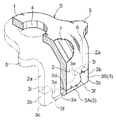
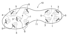
図1〜図8は、靴用スパイクの一例で、野球用スパイクシューズ10の靴底11に取付けられるスパイクSを示す。
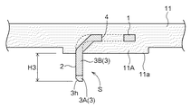
このスパイクSには、合成樹脂製の靴底11のスパイク取付け相当箇所において厚肉形成された取付け座11Aに埋設状態で取付けられる取付け基部1と、当該取付け基部1に対して直角又は略直角に折り曲げられて取付け座11Aの靴底表面11aから一部が突出する爪板部2とが備えられているとともに、前記爪板部2の先端側には、これの板厚と同じ厚みに構成され、且つ、当該爪板部よりも大きな硬度を有する耐摩耗性部材3が、溶接手段(溶接法)の一例であるろう付け法により接合されている。
[First Embodiment]
FIGS. 1-8 is an example of the spike for shoes, and shows the spike S attached to the sole 11 of the spike shoes 10 for baseball.
The spike S includes a
前記スパイクSの取付け基部1及び爪板部2は、炭素工具鋼鋼材(JIS4401)のSK−86(SK5)製で焼入れ硬度がHRC(ロックウェルCスケール硬さ)44〜47の板材を折り曲げ形成して構成されている。
The
前記耐摩耗性部材3は、超硬合金の一例である炭化タングステン(タングステン・カーバイド)製で、前記取付け基部1及び爪板部2の焼入れ硬度をHRA(ロックウェルAスケール硬さ)に硬度換算した値72.5〜74.1よりも大なる硬度(HRA80〜94)のものを使用している。
当該第1実施形態では、硬度がHRA86の炭化タングステンを使用した。
The wear-
In the first embodiment, tungsten carbide having a hardness of HRA86 is used.
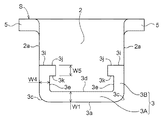
前記取付け基部1の中央部には、図1、図4に示すように、靴底11のインサート成形時に合成樹脂が入り込む抜け出し防止用の貫通孔4が形成されているとともに、取付け基部1の左右両側部位には、前記爪板部2の横方向両側の側辺2aよりも外方に突出する抜止め用の係止部5が一体形成されている。
As shown in FIGS. 1 and 4, a
また、前記取付け基部1と爪板部2との折り曲げ部位6の横方向中央位置には、図1〜図4に示すように、出隅側から入隅側への打ち出し加工によって補強リブ7が形成されている。
Further, as shown in FIGS. 1 to 4, a reinforcing
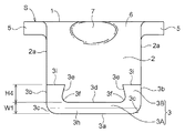
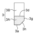
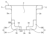
前記耐摩耗性部材3は、図2、図5に示すように、爪板部2の先端における横方向の全域に横方向に沿って配置される横向き耐摩耗部3Aと、当該横向き耐摩耗部3Aの両角部の上面3dから爪板部2の側辺2aに沿って立ち上がる左右の縦向き耐摩耗部3Bとからなり、この横向き耐摩耗部3Aと両縦向き耐摩耗部3Bとが正面視において上向きコの字状に一体形成されている。
As shown in FIGS. 2 and 5, the wear-
そのため、前記爪板部2の先端全域には、横方向に沿う横向き耐摩耗部3Aが存在し、前記爪板部2の両側辺には、横向き耐摩耗部3Aの両角部側の上面3dから爪板部2の各側辺に沿って立ち上がる縦向き耐摩耗部3Bが存在するから、爪板部2の先端での摩耗を抑制することができるとともに、爪板部2の側辺のうち、地面との接触頻度の高い横向き耐摩耗部3Aの横方向端面の上方近傍箇所における摩耗も抑制することができる。
Therefore, a lateral wear-
しかも、上向きコの字状に形成された耐摩耗性部材3と爪板部2との接合面積の増大によって接合力が強化されるから、爪板部2の接地時や蹴り出し時等において大きな外力が作用しても、耐摩耗性部材3の脱落を良好に抑制することができる。
Moreover, since the joining force is strengthened by increasing the joining area between the wear-
また、図2、図5に示すように、前記横向き耐摩耗部3Aの下面3aと両縦向き耐摩耗部3Bの外側面3bとで形成される出隅部3cが、横向き耐摩耗部3Aの縦方向の幅(以下、縦方向幅と記載する)W1よりも若干小なる半径で比較的大きな弧状面に構成されているとともに、前記横向き耐摩耗部3Aの上面3dと両縦向き耐摩耗部3Bの内側面3eとで形成される入隅部3fが、出隅部3cよりも小なる半径の弧状面に構成されている。
Further, as shown in FIGS. 2 and 5, the protruding
そのため、野球の打撃動作、投球動作、ランニング動作、守備動作などの他種多様な動作によって、爪板部2の接地時や蹴り出し時等に大きな外力がスパイクSに作用しても、耐摩耗性部材3の両出隅部3c及び両入隅部3fでの応力集中を抑止して、耐摩耗性部材3の耐衝撃性を向上することができる。
Therefore, even if a large external force acts on the spike S when the
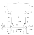
前記横向き耐摩耗部3Aは、図5、図6に示すように、横断面形状が正方形となる角棒状に構成されているとともに、当該横向き耐摩耗部3Aの下面3aと、前記取付け基部1の存在側とは反対側に位置する外表面3gとにわたって、板厚の半分に相当する寸法で45度に面取り加工された喰込み促進用の傾斜面3hが形成されている。
As shown in FIGS. 5 and 6, the lateral wear-
前記傾斜面3hの上側縁は、横方向の全域にわたって水平に構成されている。
尚、前記傾斜面3hの上側縁における横方向両側部を、横向き耐摩耗部3Aの上面3dの延長面と両縦向き耐摩耗部3Bの外側面3bとの交差箇所又はそれよりも若干上方に偏倚した位置を終点として、前記出隅部3cに沿って弧状に形成してもよい。
The upper edge of the
In addition, the both sides in the horizontal direction at the upper edge of the
図2、図5に示すように、前記横向き耐摩耗部3Aの上面3dと各縦向き耐摩耗部3Bの内側面3eとの交差位置Pを基準にして、各縦向き耐摩耗部3Bの下部における交差位置Pから外側面3bまでの横方向の幅(以下、第1横方向幅と記載する)W2が、横向き耐摩耗部3Aの縦方向幅W1よりも少し大に構成されているとともに、縦向き耐摩耗部3Bの上部である上面3iの横方向の幅(以下、第2横方向幅と記載する)W3が、縦向き耐摩耗部3Bの下部における交差位置Pでの前記第1横方向幅W2よりも大に構成されている。
As shown in FIGS. 2 and 5, the lower portion of each vertical wear-
前記各縦向き耐摩耗部3Bの第1横方向幅W2から第2横方向幅W3までは横幅が所定の比率で連続的に増加し、且つ、各縦向き耐摩耗部3Bの外側面3bと爪板部2の両側辺2aとが面一状態で一直線状に形成されているため、各縦向き耐摩耗部3Bの内側面3eが、上方ほど爪板部2の横方向中央側に位置する傾斜面に構成されている。
From the first lateral width W2 to the second lateral width W3 of each longitudinal wear-
そして、前記両縦向き耐摩耗部3Bの内側面3eとなる傾斜面が、正面視において爪板部2の横方向中央側に向ってハの字状に張り出すため、耐摩耗性部材3の抜け出し抵抗が増加するとともに、耐摩耗性部材3と爪板部2との接合面積も増大するため、耐摩耗性部材3の接合強度を高めることができる。
And since the inclined surface used as the
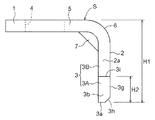
図2、図3、図5に示すように、前記耐摩耗性部材3の全高H2は、スパイクSの全高H1の約3割の寸法で、且つ、取付け座11Aの靴底表面11aから突出するスパイクSの突出高さH3の約5割の寸法に構成されているとともに、前記縦向き耐摩耗部3Bの前記交差位置Pを通る水平面(横向き耐摩耗部3Aの上面3dの延長面でもある)から上面3iまでの高さH4は、横向き耐摩耗部3Aの縦方向幅W1の約1.5倍に構成されている。
As shown in FIGS. 2, 3, and 5, the total height H2 of the wear-
図2、図5に示すように、前記爪板部2と耐摩耗性部材3との接合面が、両縦向き耐摩耗部3Bの上面3iとこれに対応する爪板部2の両第1接合面2bとが当接した状態で、前記両縦向き耐摩耗部3Bの内側面3eとこれに対応する爪板部2の両第2接合面2cとの間、及び、前記横向き耐摩耗部3Aの上面3dとこれに対応する爪板部2の第3接合面2dとの間にろうの浸透性を高める微小な隙間(当該実施形態では0.05mmの隙間に設定)が形成される寸法関係に構成され、前記爪板部2と耐摩耗性部材3とが銅ろう付けで接合されている。
As shown in FIG. 2 and FIG. 5, the joint surface between the
そのため、前記爪板部2と耐摩耗性部材3とを銅ろう付けで接合する際、両縦向き耐摩耗部3Bの上面3iとこれに当接する爪板部2の両第1接合面2bとが、爪板部2と耐摩耗性部材3とを設定接合位置関係に確定するための組付け基準面となる。
Therefore, when the
しかも、両縦向き耐摩耗部3Bの上面3iとこれに対応する爪板部2の両第1接合面2bとの当接によって設定接合位置関係が確定された状態では、両縦向き耐摩耗部3Bの内側面3eとこれに対応する爪板部2の両第2接合面2cとの間、及び、横向き耐摩耗部3Aの上面3dとこれに対応する爪板部2の第3接合面2dとの間に形成されている微小な隙間によって銅ろうの浸透性が高まり、爪板部2と耐摩耗性部材3との接合強度を向上することができる。
In addition, in the state where the set joint positional relationship is determined by the contact between the
尚、前記爪板部2と耐摩耗性部材3との接合面を構成するにあたって、両縦向き耐摩耗部3Bの上面3iとこれに対応する爪板部2の両第1接合面2bとが当接した状態で、前記両縦向き耐摩耗部3Bの内側面3eとこれに対応する爪板部2の両第2接合面2cとの間、及び、前記横向き耐摩耗部3Aの上面3dとこれに対応する爪板部2の第3接合面2dとの間の一部に微小な隙間が形成される寸法関係に構成してもよい。
In constructing the joint surface between the
また、両縦向き耐摩耗部3Bの上面3iとこれに対応する爪板部2の両第1接合面2bとを当接させるにあたって、この両縦向き耐摩耗部3Bの上面3iと爪板部2の両第1接合面2bとの全域を当接させてもよいが、両縦向き耐摩耗部3Bの上面3iと爪板部2の両第1接合面2bとの横方向両端部のみを当接させて、当該上面3iと第1接合面2bとの間の横方向中間部にろうの浸透性を高める微小な隙間を形成してもよい。
Further, when the
〔第2実施形態〕
図9は、上述の第1実施形態で説明した耐摩耗性部材3の変形例を示し、爪板部2の先端における横方向の全域に横方向に沿って配置される横向き耐摩耗部3Aと、当該横向き耐摩耗部3Aの両角部の上面3dから爪板部2の側辺2aに沿って立ち上がる左右の縦向き耐摩耗部3Bとのうち、前記各縦向き耐摩耗部3Bの上端部には、正面視において爪板部2の横方向中央側に向って突出する内向き突起部3Cが一体形成されている。
[Second Embodiment]
FIG. 9 shows a modification of the wear-
また、前記両縦向き耐摩耗部3Bの横方向の幅W4は、その縦方向の全域にわたって同一に構成されているとともに、この両縦向き耐摩耗部3Bの横方向幅W4と横向き耐摩耗部3Aの縦方向幅W1及び両内向き突起部3Cの縦方向の幅W5とが同一又は略同一に構成されている。
Further, the lateral width W4 of the both vertical wear-
さらに、前記両縦向き耐摩耗部3Bの外側面3bと、両内向き突起部3Cの上面3jと面一にある両縦向き耐摩耗部3Bの上面3iとで形成される出隅部は直角に構成され、両縦向き耐摩耗部3Bの内側面3eと両内向き突起部3Cの下面3kとで形成される入隅部も直角に構成されている。
Further, the protruding corner formed by the
尚、その他の構成は、上述の第1実施形態で説明した構成と同一であるから、同一の構成箇所には、第1実施形態と同一の番号を付記してそれの説明は省略する。
また、この第2実施形態において、前記両縦向き耐摩耗部3Bの横方向幅W4を横向き耐摩耗部3Aの縦方向幅W1よりも大又は小に構成してもよい。
In addition, since the other structure is the same as the structure demonstrated in the above-mentioned 1st Embodiment, the same number is attached to the same component location as 1st Embodiment, and the description is abbreviate | omitted.
In the second embodiment, the lateral width W4 of the both vertical wear-
さらに、この第2実施形態において、前記両内向き突起部3Cの縦方向幅W5を横向き耐摩耗部3Aの縦方向幅W1よりも大又は小に構成してもよい。
Furthermore, in the second embodiment, the longitudinal width W5 of the both inward projections 3C may be configured to be larger or smaller than the longitudinal width W1 of the lateral wear-
〔第3実施形態〕
図10は、上述の第1実施形態で説明した耐摩耗性部材3の変形例を示し、爪板部2の先端のうち、横方向の中央部を除く角部側に横方向に沿って配置される左右の横向き耐摩耗部3Aと、両横向き耐摩耗部3Aの横方向外側端部である角部の上面から爪板部2の側辺に沿って立ち上がる左右の縦向き耐摩耗部3Bとからなり、横方向両側で対をなす横向き耐摩耗部3Aと縦向き耐摩耗部3Bとが正面視においてLの字状に一体形成されている。
[Third Embodiment]
FIG. 10 shows a modified example of the wear-
そのため、前記両横向き耐摩耗部3Aの隣接間において、前記爪板部2の中央先端2eが両横向き耐摩耗部3Aの下面3aと面一状態で現れる。
Therefore, the
また、前記両縦向き耐摩耗部3Bの横方向の幅W4は、その縦方向の全域にわたって同一に構成されているとともに、この両縦向き耐摩耗部3Bの横方向幅W4と横向き耐摩耗部3Aの縦方向幅W1とが同一又は略同一に構成されている。
Further, the lateral width W4 of the both vertical wear-
尚、その他の構成は、第1実施形態で説明した構成と同一であるから、同一の構成箇所には、第1実施形態と同一の番号を付記してそれの説明は省略する。
また、この第3実施形態において、前記両縦向き耐摩耗部3Bの横方向幅W4を横向き耐摩耗部3Aの縦方向幅W1よりも大又は小に構成してもよい。
In addition, since the other structure is the same as the structure demonstrated in 1st Embodiment, the same number is attached to the same structure location as 1st Embodiment, and the description is abbreviate | omitted.
In the third embodiment, the lateral width W4 of the both vertical wear-
〔第4実施形態〕
上述の第3実施形態では、爪板部2の先端の角部側に横方向に沿って配置される左右の横向き耐摩耗部3Aと、両横向き耐摩耗部3Aの角部の上面3dから爪板部2の側辺2aに沿って立ち上がる左右の縦向き耐摩耗部3Bとを夫々Lの字状に一体形成したが、左右の側辺での摩耗が異なる場合には、図11に示すように、摩耗の少ない一方の側辺側を、横向き耐摩耗部3Aの単独から構成し、摩耗の多い他方の側辺側を、横向き耐摩耗部3Aと縦向き耐摩耗部3Bとから構成してもよい。
[Fourth Embodiment]
In the above-described third embodiment, the left and right sideways wear-
尚、その他の構成は、第1実施形態で説明した構成と同一であるから、同一の構成箇所には、第1実施形態と同一の番号を付記してそれの説明は省略する。 In addition, since the other structure is the same as the structure demonstrated in 1st Embodiment, the same number is attached to the same structure location as 1st Embodiment, and the description is abbreviate | omitted.
〔その他の実施形態〕
(1)上述の第1実施形態では、インサート成形によってスパイクSの取付け基部1を靴底11のスパイク取付け相当箇所に埋設状態で固定したが、この取付け方法に限定されるものではなく、例えば、スパイクSの取付け基部1を釘やボルト等で靴底に固定してもよい。
要するに、前記取付け基部1としては靴底11に取付けることのできるものであれば、如何なる形状に構成してもよい。
[Other Embodiments]
(1) In the above-described first embodiment, the mounting
In short, the
(2)上述の第1実施形態では、前記耐摩耗性部材3を、超硬合金の一例である炭化タングステンから構成したが、周期律表IVa,Va,VIa族金属の炭化物をFe,Co,Niなどの鉄系金属で焼結した超硬合金の複合素材から適宜選択して実施してもよい。
また、前記スパイクSの取付け基部1及び爪板部2を、上述の第1実施形態では炭素工具鋼鋼材から構成したが、それ例外の炭素鋼を使用してもよい。
要するに、前記スパイクSの取付け基部1及び爪板部2としては、スパイクSの使用条件に適した金属材料又は非金属材料の中から適宜選択するとよく、さらに、前記耐摩耗性部材3としては、爪板部2よりも硬度の大きな耐摩耗性に優れた金属材料又は非金属材料の中から適宜選定するとよい。
(2) In the first embodiment described above, the wear-
Moreover, although the
In short, the mounting
(3)上述の第1実施形態では、前記爪板部2と耐摩耗性部材3とを銅ろう付けで接合したが、この爪板部2及び耐摩耗性部材3の材質によっては金ろう、パラジウムろう、銀ろう等を用いて接合してもよい。
(3) In the first embodiment described above, the
(4)上述の第1実施形態では、前記爪板部2と耐摩耗性部材3とをろう付け法で接合したが、この爪板部2と耐摩耗性部材3とをティグ溶接(TIG溶接)法、ミグ溶接(MIG溶接)法、電子ビーム溶接法、レーザビーム溶接法、抵抗溶接法、摩擦圧接法、拡散接合法の中から適切な接合法を選択して接合してもよい。
(4) In the above-described first embodiment, the
(5)上述の各実施形態において、前記爪板部2と耐摩耗性部材3との接合面を構成するにあたって、接合面長手方向の少なくとも二箇所において当接する位置決め当接部と、位置決め当接部以外の部位においてろうの浸透性を高める微小な隙間とが形成される寸法関係に構成して、前記爪板部2と耐摩耗性部材3とをろう付けで接合してもよい。
(5) In each of the above-described embodiments, the positioning contact portion that contacts at least two locations in the longitudinal direction of the joint surface when positioning the joint surface between the
本願発明は、爪板部の側辺での摩耗進行に起因する折損や耐摩耗性部材の脱落を抑制して、長期にわたって確実・良好なスパイク機能を発揮させることのできる靴用スパイクとして良好に利用することができる。 The present invention is excellent as a spike for shoes that can suppress breakage due to the progress of wear on the side of the nail plate portion and drop-off of the wear-resistant member, and can exhibit a reliable and good spike function over a long period of time. Can be used.
W1 縦方向幅
W2 横方向幅
W3 横方向幅
1 取付け基部
2 爪板部
2b 第1接合部
2c 第2接合部
2d 第3接合部
3 耐摩耗性部材
3A 横向き耐摩耗部
3B 縦向き耐摩耗部
3d 上面
3e 内側面
3f 入隅部
3j 上面
11 靴底
W1 Longitudinal width W2 Horizontal width
Claims (7)
前記耐摩耗性部材が、少なくとも爪板部の先端の角部側において横方向に沿う横向き耐摩耗部と、当該横向き耐摩耗部の角部側の上面から爪板部の側辺に沿って立ち上がる縦向き耐摩耗部とから構成されている靴用スパイク。 A spike for shoes in which a wear-resistant member having a hardness greater than that of the nail plate portion is joined to the tip end side of the nail plate portion connected to the attachment base that can be attached to the shoe sole,
The wear-resistant member rises along a lateral side of the claw plate part from a lateral wear-resistant part extending along the lateral direction at least at the corner side of the tip of the claw plate part, and an upper surface on the corner part side of the lateral wear-resistant part. A spike for shoes composed of a vertical wear-resistant part.
Priority Applications (1)
| Application Number | Priority Date | Filing Date | Title |
|---|---|---|---|
| JP2011094310A JP5385938B2 (en) | 2011-04-20 | 2011-04-20 | Spikes for shoes |
Applications Claiming Priority (1)
| Application Number | Priority Date | Filing Date | Title |
|---|---|---|---|
| JP2011094310A JP5385938B2 (en) | 2011-04-20 | 2011-04-20 | Spikes for shoes |
Publications (2)
| Publication Number | Publication Date |
|---|---|
| JP2012223402A true JP2012223402A (en) | 2012-11-15 |
| JP5385938B2 JP5385938B2 (en) | 2014-01-08 |
Family
ID=47274281
Family Applications (1)
| Application Number | Title | Priority Date | Filing Date |
|---|---|---|---|
| JP2011094310A Expired - Fee Related JP5385938B2 (en) | 2011-04-20 | 2011-04-20 | Spikes for shoes |
Country Status (1)
| Country | Link |
|---|---|
| JP (1) | JP5385938B2 (en) |
Citations (5)
| Publication number | Priority date | Publication date | Assignee | Title |
|---|---|---|---|---|
| JPS57175607U (en) * | 1981-04-28 | 1982-11-06 | ||
| JPS59150310U (en) * | 1983-03-08 | 1984-10-08 | 京セラ株式会社 | spikes for athletic shoes |
| JPH0537106U (en) * | 1991-10-30 | 1993-05-21 | サンアロイ工業株式会社 | Spike chip with cemented carbide coating |
| JP2007312856A (en) * | 2006-05-23 | 2007-12-06 | Asics Corp | Stud and spiked shoe |
| JP2012034739A (en) * | 2010-08-04 | 2012-02-23 | Kaji Tech Co Ltd | Spike and spike shoes with the spike for baseball |
-
2011
- 2011-04-20 JP JP2011094310A patent/JP5385938B2/en not_active Expired - Fee Related
Patent Citations (5)
| Publication number | Priority date | Publication date | Assignee | Title |
|---|---|---|---|---|
| JPS57175607U (en) * | 1981-04-28 | 1982-11-06 | ||
| JPS59150310U (en) * | 1983-03-08 | 1984-10-08 | 京セラ株式会社 | spikes for athletic shoes |
| JPH0537106U (en) * | 1991-10-30 | 1993-05-21 | サンアロイ工業株式会社 | Spike chip with cemented carbide coating |
| JP2007312856A (en) * | 2006-05-23 | 2007-12-06 | Asics Corp | Stud and spiked shoe |
| JP2012034739A (en) * | 2010-08-04 | 2012-02-23 | Kaji Tech Co Ltd | Spike and spike shoes with the spike for baseball |
Also Published As
| Publication number | Publication date |
|---|---|
| JP5385938B2 (en) | 2014-01-08 |
Similar Documents
| Publication | Publication Date | Title |
|---|---|---|
| US20060217216A1 (en) | Fairway wood with titanium face member | |
| US20020195280A1 (en) | Roof bit body and insert assembly | |
| JP2002126134A (en) | Golf club | |
| JP2010005281A (en) | Iron golf club head | |
| KR102694620B1 (en) | Golf club head | |
| JP2009226062A (en) | Iron golf club head and its manufacturing method | |
| US10100498B2 (en) | Lip and shroud assembly | |
| JP2008272241A (en) | Iron golf club | |
| JP6123468B2 (en) | Iron type golf club head | |
| JP4002514B2 (en) | Tamping Tyne | |
| EP4101611A1 (en) | Saw blade | |
| JP5836211B2 (en) | Iron golf club and iron golf club set | |
| JP5385938B2 (en) | Spikes for shoes | |
| CN103537867B (en) | Forged golf club head manufacturing method | |
| JP6740648B2 (en) | Golf club head | |
| JP2003047678A (en) | Golf club head | |
| JP5810617B2 (en) | Iron head | |
| JP2007009631A (en) | Bucket | |
| JP2008161308A (en) | Iron golf club head | |
| JP4049436B2 (en) | Rigid reinforced iron golf head | |
| JP6759637B2 (en) | Golf club head | |
| JP2020049186A (en) | Iron type golf club head and iron type golf club set | |
| CN222745156U (en) | A bimetallic composite reamer tooth | |
| JP2001309999A (en) | Golf club head | |
| JP2019092847A (en) | Spike fitting for shoe |
Legal Events
| Date | Code | Title | Description |
|---|---|---|---|
| A131 | Notification of reasons for refusal |
Free format text: JAPANESE INTERMEDIATE CODE: A131 Effective date: 20130307 |
|
| A521 | Written amendment |
Free format text: JAPANESE INTERMEDIATE CODE: A523 Effective date: 20130507 |
|
| A131 | Notification of reasons for refusal |
Free format text: JAPANESE INTERMEDIATE CODE: A131 Effective date: 20130606 |
|
| A521 | Written amendment |
Free format text: JAPANESE INTERMEDIATE CODE: A523 Effective date: 20130805 |
|
| TRDD | Decision of grant or rejection written | ||
| A01 | Written decision to grant a patent or to grant a registration (utility model) |
Free format text: JAPANESE INTERMEDIATE CODE: A01 Effective date: 20130905 |
|
| A61 | First payment of annual fees (during grant procedure) |
Free format text: JAPANESE INTERMEDIATE CODE: A61 Effective date: 20131004 |
|
| R150 | Certificate of patent or registration of utility model |
Free format text: JAPANESE INTERMEDIATE CODE: R150 |
|
| R250 | Receipt of annual fees |
Free format text: JAPANESE INTERMEDIATE CODE: R250 |
|
| LAPS | Cancellation because of no payment of annual fees |