JP2012219712A5 - - Google Patents
Download PDFInfo
- Publication number
- JP2012219712A5 JP2012219712A5 JP2011086080A JP2011086080A JP2012219712A5 JP 2012219712 A5 JP2012219712 A5 JP 2012219712A5 JP 2011086080 A JP2011086080 A JP 2011086080A JP 2011086080 A JP2011086080 A JP 2011086080A JP 2012219712 A5 JP2012219712 A5 JP 2012219712A5
- Authority
- JP
- Japan
- Prior art keywords
- blade
- impeller
- wing
- counter
- blades
- Prior art date
- Legal status (The legal status is an assumption and is not a legal conclusion. Google has not performed a legal analysis and makes no representation as to the accuracy of the status listed.)
- Granted
Links
Images
Description
本発明は、前段インペラと後段インペラとが逆方向に回転する二重反転式軸流送風機に関するものである。 The present invention relates to a counter-rotating axial flow fan in which a front impeller and a rear impeller rotate in opposite directions.
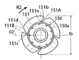
図1及び図2には、特許第4128194号公報(特許文献1)に記載の従来の二重反転式軸流送風機の構造が示されている。図1(A)、(B)、(C)及び(D)は、特許第4128194号公報(特許文献1)に記載の従来の二重反転式軸流送風機の吸い込み側から見た斜視図、吐き出し側から見た斜視図、吸い込み側から見た正面図、吐き出し側から見た背面図、図2(A)は図1の二重反転式軸流送風機の縦断面図であり、図2(B)は図1の二重反転式軸流送風機の前段翼であり、図2(C)は図1の二重反転式軸流送風機の後段翼である。なお図2は、説明のために、特許第4128194号公報に示された符号及び寸法表示を一部変更してある。従来の二重反転式軸流送風機は、第1の単体軸流送風機1と第2の単体軸流送風機3とが結合構造を介して組み合わされて構成されている。第1の単体軸流送風機1は、第1のケース5と、該第1のケース5内にそれぞれ配置される第1のインペラ(前段インペラ)7と、第1のモータ25と、周方向に120°の間隔をあけて並ぶ3本のウエブ21とを有している。第1のケース5は、軸線Aが延びる方向(軸線方向)の一方側に環状の吸い込み側フランジ9を有し、軸線方向の他方側に環状の吐き出し側フランジ11を有している。また第1のケース5は、両フランジ9,11の間に筒部13を有している。フランジ9とフランジ11と筒部13の内部空間により、風洞が構成されている。吐き出し側フランジ11は内部に円形の吐出口17を有している。3本のウエブ21は、第2の単体軸流送風機3の後述する3本のウエブ45とそれぞれ組み合わされて、3枚の静止翼61が構成されている。第1のモータ25は、第1のケース5内で第1のインペラ7を図1(A)及び(C)に示した状態で反時計回り方向(図示の矢印R1の方向即ち一方の方向)に回転させる。第1のモータ25は、後述する第2のインペラ35(後段インペラ)の回転速度よりも速い速度で第1のインペラ7を回転させる。第1のインペラ7は、第1のモータ25の図示しない回転軸に固定される図示しないロータのカップ状部材に嵌合される環状部材(ハブ)27と、この環状部材27の環状の周壁27aの外周面に一体に設けられたN枚(5枚)の前方ブレード28(前段翼)とを有している。 1 and 2 show the structure of a conventional counter-rotating axial flow fan described in Japanese Patent No. 4128194 (Patent Document 1). 1 (A), (B), (C) and (D) are perspective views as seen from the suction side of a conventional counter-rotating axial flow fan described in Japanese Patent No. 4128194 (Patent Document 1). The perspective view seen from the discharge side, the front view seen from the suction side, the rear view seen from the discharge side, FIG. 2 (A) is a longitudinal sectional view of the counter-rotating axial flow fan of FIG. B) is a front blade of the counter rotating axial flow fan of FIG. 1, and FIG. 2C is a rear blade of the counter rotating axial flow fan of FIG. In FIG. 2, for the sake of explanation, the reference numerals and dimensions shown in Japanese Patent No. 4128194 are partially changed. The conventional counter-rotating axial flow fan is configured by combining a first single axial flow fan 1 and a second single axial flow blower 3 through a coupling structure. The first single axial blower 1 includes a first case 5, a first impeller (pre-stage impeller) 7 disposed in the first case 5, a first motor 25, and a circumferential direction. And three webs 21 arranged at intervals of 120 °. The first case 5 has an annular suction side flange 9 on one side in the direction in which the axis A extends (axial direction), and an annular discharge side flange 11 on the other side in the axial direction. The first case 5 has a cylindrical portion 13 between the flanges 9 and 11. A wind tunnel is formed by the internal space of the flange 9, the flange 11, and the cylindrical portion 13. The discharge side flange 11 has a circular discharge port 17 inside. The three webs 21 are combined with three webs 45, which will be described later, of the second single axial blower 3 to form three stationary blades 61. The first motor 25 moves the first impeller 7 in the first case 5 in the counterclockwise direction in the state shown in FIGS. 1A and 1C ( the direction of the arrow R1 in the drawing, that is, one direction). Rotate to The first motor 25 rotates the first impeller 7 at a speed higher than the rotational speed of a second impeller 35 (rear stage impeller) described later. The first impeller 7 has an annular member (hub) 27 fitted to a cup-like member of a rotor (not shown) fixed to a rotary shaft (not shown) of the first motor 25, and an annular peripheral wall 27 a of the annular member 27. And N (five) front blades 28 (front wings) provided integrally on the outer peripheral surface.
第2の単体軸流送風機3は、第2のケース33とこの第2のケース33内に配置される図2(A)に示す第2のインペラ(後段インペラ)35と、第2のモータ49と、3本のウエブ45とを有している。第2のケース33は、図1に示すように、軸線Aが延びる方向(軸線方向)の一方側に吸い込み側フランジ37を有し、軸線Aが延びる方向の他方側に吐き出し側フランジ39を有している。また第2のケース33は、両フランジ37,39の間に筒部41を有している。そしてフランジ37とフランジ39と筒部41の内部空間により、風洞が構成されている。また第1のケース5と第2のケース33とによりケーシングが構成されている。吸い込み側フランジ37は、内部に円形の吸込口42を有している。第2のモータ49は、第2のケース33内で第2のインペラ35を図1(B)及び(D)に示した状態で反時計回り方向[図示の矢印R2の方向、即ち、第1のインペラ7の回転方向(矢印R1)と逆方向(他方の方向)]に第2のインペラ35を回転させる。前述したように、第2のインペラ35は、第1のインペラ7の回転速度よりも遅い速度で回転させられる。第2のインペラ35は、第2のモータ49の図示しない回転軸に固定される図示しないロータのカップ状部材に嵌合される環状部材50と、この環状部材(ハブ)50の環状の周壁50aの外周面に一体に設けられたP枚(4枚)の後方ブレード51(後段翼)とを有している。 The second single axial fan 3 includes a second case 33, a second impeller (rear stage impeller) 35 shown in FIG. 2A disposed in the second case 33, and a second motor 49. And three webs 45. As shown in FIG. 1, the second case 33 has a suction side flange 37 on one side in the direction in which the axis A extends (axis direction), and a discharge side flange 39 on the other side in the direction in which the axis A extends. doing. The second case 33 has a cylindrical portion 41 between both flanges 37 and 39. A wind tunnel is formed by the internal space of the flange 37, the flange 39, and the cylindrical portion 41. The first case 5 and the second case 33 constitute a casing. The suction side flange 37 has a circular suction port 42 therein. The second motor 49 moves the second impeller 35 in the second case 33 in the counterclockwise direction in the state shown in FIGS. 1B and 1D [the direction of the arrow R2 shown in FIG. The second impeller 35 is rotated in the direction opposite to the rotation direction of the impeller 7 (arrow R1) (the other direction). As described above, the second impeller 35 is rotated at a speed slower than the rotation speed of the first impeller 7. The second impeller 35 includes an annular member 50 fitted to a cup-like member of a rotor (not shown) fixed to a rotation shaft (not shown) of the second motor 49, and an annular peripheral wall 50 a of the annular member (hub) 50. P blades (four blades) rear blades 51 (rear blades) provided integrally on the outer peripheral surface.
なお図2(B)に示すように前方ブレード28(前段翼)は、後退翼から構成されている。また前方ブレード28(前段翼)は、横断面形状が前述の一方の方向(インペラの回転方向)R1に向かって凹部が開口する湾曲形状を有している。図2(C)に示すように、後方ブレード(後段翼)51も後退翼からなる。また後方ブレード(後段翼)51は、横断面形状が他方の方向(インペラの回転方向)R2に向かって凹部が開口する湾曲形状を有している。そして静止翼即ちストラッド61は、横断面形状が他方の方向R2と後方ブレード51が位置する方向とに向かって凹部が開口する湾曲形状を有している。 As shown in FIG. 2B, the front blade 28 (the front blade) is composed of a retracted blade. Further, the front blade 28 (front blade) has a curved shape in which a concave portion is opened in the above-described one direction (rotation direction of the impeller) R1. As shown in FIG. 2 (C), the rear blade (rear blade) 51 is also composed of a retracted blade. Further, the rear blade (rear blade) 51 has a curved shape in which a recess opens toward the other direction (rotation direction of the impeller) R2 in the cross-sectional shape. The stationary blade, that is, the stradd 61, has a curved shape in which a recess opens toward the other direction R2 and the direction in which the rear blade 51 is located.
従来の二重反転式軸流送風機では、N枚の前方ブレード28の枚数と、M枚のストラッド61の枚数と、P枚の後方ブレード51の枚数との関係は、N,M及びPが、それぞれ正の整数であってN>P>Mの関係となっている。 In the conventional counter-rotating axial blower, the relationship between the number of N front blades 28, the number of M straddles 61, and the number of P rear blades 51 is N, M, and P. Each is a positive integer and has a relationship of N> P> M.
また筒部13及び33からなる風洞の内壁部の軸線方向の両端部の四隅には、吸込口15及び吐出口57に向かって径寸法が大きくなる4つの湾曲面部分18及び58が形成されている。これら4つの湾曲面部分18及び58は、風洞の内壁部の直径をRoとしたときに、湾曲面部分18及び58の最大径となる端の位置における最大径寸法Rmはほぼ1.06Roとなる形状を有している。また前方ブレード28(前段翼)の外径寸法をRfとすると、前方ブレード28(前段翼)とストラッド61との間の最小クリアランスCfが、Rf/6より小さい。また後方ブレード51(後段翼)の外径寸法をRrとしたときに、後方ブレード51(後段翼)とストラッドとの間の最小クリアランスCrは、Rr/8より小さい。 In addition, four curved surface portions 18 and 58 whose diameters are increased toward the suction port 15 and the discharge port 57 are formed at the four corners of both end portions in the axial direction of the inner wall portion of the wind tunnel including the cylindrical portions 13 and 33. Yes. These four curved surface portions 18 and 58 have a maximum diameter dimension Rm of approximately 1.06 Ro at the end position where the maximum diameter of the curved surface portions 18 and 58 becomes Ro when the diameter of the inner wall portion of the wind tunnel is Ro. It has a shape. Further, when the outer diameter of the front blade 28 (front blades) and R f, the minimum clearance C f between the struts 61 and the front blade 28 (front blades) is, R f / 6 smaller. The minimum clearance C r between the outer diameter dimension is taken as R r, rear blades 51 (the rear blades) and struts of the rear blades 51 (the rear blades) is less than R r / 8.
従来の二重反転式軸流送風機でも、風量と静圧の特性を向上させることはできるが、さらに消費電力及び騒音の低減が望まれている。 Even with the conventional counter-rotating axial flow fan, the characteristics of air volume and static pressure can be improved, but further reduction of power consumption and noise is desired.
本発明の目的は、従来よりも、風量と静圧の特性を向上させることができて、しかも消費電力及び騒音を低減できる二重反転式軸流送風機を提供することにある。 An object of the present invention is to provide a counter-rotating axial flow fan that can improve the characteristics of air volume and static pressure and can reduce power consumption and noise.
本発明の二重反転式軸流送風機は、軸線方向の一方側に吸込口を有し軸線方向の他方側に吐出口を有する風洞を備えたケーシングと、風洞内で回転する複数の前段翼を備えた前段インペラと、風洞内で前段インペラとは逆方向に回転する複数の後段翼を備えた後段インペラと、風洞内の前段インペラと後段インペラとの間に位置し、静止状態で配置された複数個のストラッド(またはウエブ)とを有する。 The counter-rotating axial flow fan of the present invention comprises a casing having a wind tunnel having a suction port on one side in the axial direction and a discharge port on the other side in the axial direction, and a plurality of front blades rotating in the wind tunnel. Located between the front impeller and the rear impeller provided in the wind tunnel, the rear impeller including a plurality of rear blades rotating in the opposite direction to the front impeller in the wind tunnel, and disposed in a stationary state A plurality of straddles (or webs).
本発明においては、複数の前段翼が後退翼からなり、複数の後段翼が前進翼からなる。 In the present invention, the plurality of front-stage blades are made of receding wings, and the plurality of rear-stage blades are made of forward wings.
理由は定かではないが、前段翼として後退翼を用い、後段翼として前進翼を用いると、風量と静圧の特性を向上させることができて、しかも消費電力を低減し且つ騒音の発生を低減できる。なお本願明細書において、後退翼とは、翼の吸込口側端縁に対して翼の吐出口側端縁がインペラの回転方向とは逆方向側に位置し、翼の吸込口側端縁及び翼の吐出口側端縁が回転方向とは逆方向に向かって傾斜し且つ翼の横断面形状がインペラの回転方向に向かって凹部が開口する湾曲形状を有するものである。また前進翼とは、翼の吸込口側端縁に対して翼の吐出口側端縁がインペラの回転方向とは逆方向側に位置し、翼の吸込口側端縁及び翼の吐出口側端縁が回転方向に向かって傾斜し且つ翼の横断面形状がインペラの回転方向に向かって凹部が開口する湾曲形状を有するものである。 The reason is not clear, but using a retracted blade as the front blade and a forward blade as the rear blade can improve the air flow and static pressure characteristics, reduce power consumption and reduce noise generation. it can. In the present specification, the swept wing means that the discharge port side edge of the blade is located on the opposite side to the rotation direction of the impeller relative to the suction port side edge of the blade, and the suction port side edge of the blade and The discharge port side edge of the blade is inclined in the direction opposite to the rotation direction, and the cross-sectional shape of the blade has a curved shape in which the recess opens toward the rotation direction of the impeller. The forward wing means that the blade discharge port side edge is located on the opposite side of the impeller rotation direction with respect to the blade suction port side edge, and the blade suction port side edge and blade discharge port side The edge is inclined toward the rotation direction, and the cross-sectional shape of the wing has a curved shape in which the recess opens toward the rotation direction of the impeller.
なお前段翼の枚数をN、ストラッドの個数をM、後段翼の枚数をP(但し、N,M及びPは全て正の整数)とした場合、N≧P>Mの関係が満たされているのが好ましい。また前段翼の回転速度が後段翼の回転速度よりも速いことが好ましい。この関係は、二重反転式軸流送風機において好ましい関係であることを過去に出願人が見出したものであるが、この関係は本発明においても有効であることが確認された。 When the number of front blades is N, the number of straddles is M, and the number of rear blades is P (where N, M, and P are all positive integers), the relationship of N ≧ P> M is satisfied. Is preferred. Further, it is preferable that the rotation speed of the front blade is higher than the rotation speed of the rear blade. The applicant has previously found that this relationship is a preferable relationship in the counter-rotating axial flow fan, but it has been confirmed that this relationship is also effective in the present invention.
上記関係に加えて、風洞の内壁部の軸線方向の両端部に、吸込口または吐出口に向かって径寸法が大きくなる複数の湾曲面部分が形成されていることが、風量と静圧の特性の向上と、騒音の低減には好ましい。但し、この湾曲面部分は、風洞の内壁部の直径をRoとしたときに、湾曲面部分の最大径となる端の位置において最大径寸法Rmは(1.02±0.01)Roであると、その効果は確実なものとなる。 In addition to the above relationship, the air volume and static pressure characteristics are that a plurality of curved surface portions whose diameters increase toward the suction port or the discharge port are formed at both ends in the axial direction of the inner wall portion of the wind tunnel. It is preferable for improvement of noise and reduction of noise. However, this curved surface portion has a maximum diameter dimension Rm of (1.02 ± 0.01) Ro at the end of the curved surface portion where the diameter of the inner wall portion of the wind tunnel is Ro. And the effect is certain.
また前段翼の外径寸法をRfとしたときに、前段翼とストラッドとの間の最小クリアランスCfが、Rf/4>Cf>Rf/6の範囲の値であると、消費電力を低減して、しかも騒音を低減できる。 The outside diameter of the front blades to when the R f, the minimum clearance C f between the front blades and struts is, if it is a value in the range of R f / 4> C f> R f / 6, consumption Electric power can be reduced and noise can be reduced.
さらに後段翼の外径寸法をRrとしたときに、後段翼とストラッドとの間の最小クリアランスCrが、Rr/6>Cr>Rr/8の範囲の値であると、さらに消費電力と騒音を低減できる。 Furthermore, when the outer diameter dimension of the rear blade is R r , the minimum clearance C r between the rear blade and the straddle is a value in the range of R r / 6> C r > R r / 8. Power consumption and noise can be reduced.
以下図面を参照して本発明の二重反転式軸流送風機の実施の形態について説明する。図3は、本発明の二重反転式軸流送風機の一実施の形態の構成の概略を説明するための半部断面図である。図3の二重反転式軸流送風機は、図1及び図2に示した従来の二重反転式軸流送風機と、前段インペラ107の形状、後段インペラ135の形状及びストラッド161の形状が異なる点を除いて、基本的には同様である。したがって本実施の形態において、図1及び図2の従来の二重反転式軸流送風機を構成する部分と同様の部分には、図1及び図2に付した符号の数に100の数を加えた符号を付す。第1の単体軸流送風機101と第2の単体軸流送風機103とが結合構造を介して組み合わされて構成されている。第1の単体軸流送風機101は、第1のケース105と、該第1のケース105内にそれぞれ配置される第1のインペラ(前段インペラ)107と、第1のモータ125と、第1のケースの周方向に120°の間隔をあけて並ぶ3本のウエブ121とを有している。第1のケース105は、軸線Aが延びる方向(軸線方向)の一方側に環状の吸い込み側フランジ109を有し、軸線方向の他方側に環状の吐き出し側フランジ111を有している。また第1のケース105は、両フランジ109,111の間に筒部113を有している。フランジ109とフランジ111と筒部113の内部空間により、風洞が構成されている。吐き出し側フランジ111は内部に円形の吐出口117を有している。3本のウエブ121は、第2の単体軸流送風機103の後述する3本のウエブ145とそれぞれ組み合わされて、3個のストラッド161が構成されている。第1のモータ125は、第1のケース105内で第1のインペラ107を反時計回り方向に回転させる。第1のモータ125は、後述する第2のインペラ135(後段インペラ)の回転速度よりも速い速度で第1のインペラ107を回転させる。 Embodiments of a counter-rotating axial flow fan of the present invention will be described below with reference to the drawings. FIG. 3 is a half sectional view for explaining the outline of the configuration of the embodiment of the counter-rotating axial flow fan of the present invention. The counter-rotating axial fan shown in FIG. 3 is different from the conventional counter-rotating axial fan shown in FIGS. 1 and 2 in the shape of the front impeller 107, the shape of the rear impeller 135, and the shape of the straddle 161. Basically the same except for. Therefore, in the present embodiment, the same number as that constituting the conventional counter-rotating axial flow fan shown in FIGS. 1 and 2 is added with the number of 100 in FIG. 1 and FIG. The code is attached. The first single axial fan 101 and the second single axial fan 103 are combined through a coupling structure. The first single axial blower 101 includes a first case 105, a first impeller (pre-stage impeller) 107 disposed in the first case 105, a first motor 125 , And three webs 121 arranged at intervals of 120 ° in the circumferential direction of the case . The first case 105 has an annular suction side flange 109 on one side in the direction in which the axis A extends (axial direction), and an annular discharge side flange 111 on the other side in the axial direction. The first case 105 has a cylindrical portion 113 between both flanges 109 and 111. A wind tunnel is formed by the internal space of the flange 109, the flange 111, and the cylindrical portion 113. The discharge side flange 111 has a circular discharge port 117 inside. The three webs 121 are respectively combined with three webs 145 (to be described later) of the second single axial fan 103 to form three struts 161. The first motor 125 rotates the first impeller 107 counterclockwise in the first case 105. The first motor 125 rotates the first impeller 107 at a speed higher than the rotation speed of a second impeller 135 (rear stage impeller) described later.
第1のインペラ107は、第1のモータ125の回転軸126に固定される図示しないロータのカップ状部材に嵌合される環状部材であるハブ127と、このハブ127の環状の周壁127aの外周面に一体に設けられたN枚(5枚)の前方ブレード即ち前段翼128とを有している。本実施の形態では、前段翼128が、後退翼から構成されている。図4及び図6に示すように、後退翼からなる前段翼128は、翼の吸込口側端縁128Aに対して翼の吐出口側端縁128Bがインペラ107の回転方向R1とは逆方向側に位置し且つ翼の吸込口側端縁128A及び翼の吐出口側端縁128Bが回転方向R1とは逆方向に向かって傾斜し且つ翼の横断面形状がインペラ107の回転方向R1に向かって凹部128C(図6)が開口する湾曲形状を有している。ちなみに本実施の形態で用いる後退翼の傾斜角θ1は25°±3°である。翼の吸込口側端縁128A及び翼の吐出口側端縁128Bが回転方向R1とは逆方向に向かって傾斜するとは、吸込口側端縁128A及び翼の吐出口側端縁128Bのハブ127側の端部128a及び128cよりも、吸込口側端縁128A及び翼の吐出口側端縁128Bの径方向外側端部128b及び128dが回転方向R1とは逆方向側に位置していることを意味する。また本実施の形態では、前段翼128の外径寸法をRfとしたときに、前段翼128とストラッド161との間の最小クリアランスCfが、Rf/4>Cf>Rf/6の範囲に入るようにしている。具体的には、本実施の形態の最小クリアランスCfはRf/5.1である。このようにすると風量−静圧特性を向上でき、しかも消費電力を低減し、且つ騒音も低減できる。 The first impeller 107 includes a hub 127 which is an annular member fitted to a cup-shaped member of a rotor (not shown) fixed to the rotating shaft 126 of the first motor 125, and an outer periphery of an annular peripheral wall 127a of the hub 127. There are N (five) front blades, that is, front blades 128 provided integrally on the surface. In the present embodiment, the front stage blade 128 is constituted by a retracted blade. As shown in FIGS. 4 and 6, the front stage blade 128 made of a swept blade has a blade discharge port side edge 128 </ b> B opposite to the blade suction port side edge 128 </ b> A in a direction opposite to the rotation direction R <b> 1 of the impeller 107. The blade inlet end edge 128A and the blade outlet end edge 128B are inclined in the direction opposite to the rotation direction R1 and the blade cross-sectional shape is directed toward the impeller 107 rotation direction R1. The recess 128C (FIG. 6) has a curved shape that opens. Incidentally, the tilt angle θ1 of the swept wing used in the present embodiment is 25 ° ± 3 °. When the blade inlet end edge 128A and the blade outlet edge 128B of the blade are inclined in the direction opposite to the rotation direction R1, the hub 127 of the inlet port end edge 128A and the blade outlet edge 128B of the blade is assumed to be inclined. That is, the radially outer ends 128b and 128d of the suction port side edge 128A and the blade discharge port side edge 128B are located on the opposite side of the rotational direction R1 from the side ends 128a and 128c. means. In the present embodiment, when the outer diameter of the front blade 128 is R f , the minimum clearance C f between the front blade 128 and the strut 161 is R f / 4> C f > R f / 6. I am trying to be in the range. Specifically, the minimum clearance C f in the present embodiment is R f /5.1. In this way, the air volume-static pressure characteristics can be improved, power consumption can be reduced, and noise can be reduced.
また第2の単体軸流送風機103は、第2のケース133とこの第2のケース133内に配置される図3に示す第2のインペラ(後段インペラ)135と、第2のモータ149と、3本のウエブ145とを有している。第2のケース133は、図3に示すように、軸線Aが延びる方向(軸線方向)の一方側に吸い込み側フランジ137を有し、軸線Aが延びる方向の他方側に吐き出し側フランジ139を有している。また第2のケース133は、両フランジ137,139の間に筒部141を有している。そしてフランジ137とフランジ139と1筒部41の内部空間により、風洞が構成されている。また第1のケース105と第2のケース133とによりケーシングが構成されている。吸い込み側フランジ137は、内部に円形の吸込口142を有している。吐き出し側フランジ139は、内部に円形の吐出口143を有している。第2のモータ149は、第2のケース133内で第2のインペラ135を図5に示した状態で時計回り方向[図示の矢印R2の方向、即ち、第1のインペラ7の回転方向(矢印R1)と逆方向(他方の方向)]に第2のインペラ135を回転させる。前述したように、第2のインペラ135は、第1のインペラ107の回転速度よりも遅い速度で回転させられる。 The second single axial fan 103 includes a second case 133, a second impeller (rear stage impeller) 135 shown in FIG . 3 disposed in the second case 133, a second motor 149, And three webs 145. As shown in FIG. 3 , the second case 133 has a suction side flange 137 on one side in the direction in which the axis A extends (axis direction), and a discharge side flange 139 on the other side in the direction in which the axis A extends. doing. The second case 133 has a cylindrical portion 141 between the flanges 137 and 139. A wind tunnel is formed by the internal space of the flange 137, the flange 139, and the one cylinder portion 41. The first case 105 and the second case 133 constitute a casing. The suction side flange 137 has a circular suction port 142 inside. The discharge side flange 139 has a circular discharge port 143 inside. The second motor 149 rotates the second impeller 135 in the second case 133 in the clockwise direction [the direction of the arrow R2 shown in the drawing, that is, the rotation direction of the first impeller 7 (arrow The second impeller 135 is rotated in the direction opposite to R1) (the other direction). As described above, the second impeller 135 is rotated at a speed slower than the rotation speed of the first impeller 107.
図5に示すように、第2のインペラ135は、第2のモータ149の回転軸148に固定されるロータのカップ状部材に嵌合される環状部材即ちハブ150と、このハブ150の環状の周壁150aの外周面に一体に設けられたP枚(4枚)の後方ブレードすなわち後段翼151とを有している。後段翼151は、前進翼から構成される。前進翼である後段翼151は、吸込口側端縁151Aに対して翼の吐出口側端縁151Bがインペラ135の回転方向R2とは逆方向側に位置し、翼の吸込口側端縁151A及び翼の吐出口側端縁151Bが回転方向に向かって傾斜し且つ翼の横断面形状がインペラの回転方向に向かって凹部151C(図6)が開口する湾曲形状を有するものである。ちなみに本実施の形態で用いる前進翼の傾斜角θ2は30°±3°である。翼の吸込口側端縁151A及び翼の吐出口側端縁151Bが回転方向R2とは逆方向に向かって傾斜するとは、吸込口側端縁151A及び翼の吐出口側端縁151Bのハブ150側の端部151a及び151cよりも、吸込口側端縁151A及び翼の吐出口側端縁151Bの径方向外側端部151b及び151dが回転方向R2側に位置していることを意味する。また本実施の形態では、後段翼151の外径寸法をRrとしたときに、後段翼151とストラッド161との間の最小クリアランスCrが、Rr/6>Cr>Rr/8の範囲に入るようにしている。具体的には、本実施の形態の最小クリアランスCrはRr/7.1である。このようにすると風量−静圧特性を向上でき、しかも消費電力を低減し、且つ騒音も低減できる。
As shown in FIG. 5, the second impeller 135 includes an annular member or
N枚の前段翼128の枚数と、M個のストラッド161の数と、P枚の後段翼151の枚数との関係は、N,M及びPが、それぞれ正の整数であってN>P>Mの関係となっている。
The relationship between the number of N front blades 128, the number of M straddles 161, and the number of P
また図3に示すように、筒部113及び133によって構成される風洞の内壁部の軸線方向の両端部の四隅には、吸込口115及び吐出口157に向かって径寸法が大きくなる4つの湾曲面部分118及び158が形成されている。図7(A)乃至(C)には、湾曲面部分118を示している。これら4つの湾曲面部分118及び158は、風洞の内壁部の直径をRoとしたときに、湾曲面部分118の最大径となる端の位置において最大径寸法Rmは1.02Roで、風洞の開口部からの長さ寸法Lが0.08Ro以上となる形状を有している。すなわちこの湾曲面部分118及び158は、長さ寸法Lの間に内部空間の直径寸法がRoから1.02Roまで大きくなる湾曲形状を有していることになる。この最大径寸法Rmは、図1及び図2の従来の構造の湾曲面部分の最大径寸法Rmより小さい。このように径寸法が変化する湾曲面部分118及び158を設けると、風量−静圧特性を向上でき、しかも騒音の低減効果を高めることができる。 Further, as shown in FIG. 3, there are four curves whose diameters increase toward the suction port 115 and the discharge port 157 at the four corners at both ends in the axial direction of the inner wall portion of the wind tunnel constituted by the cylindrical portions 113 and 133. Surface portions 118 and 158 are formed. 7A to 7C show the curved surface portion 118. FIG. These four curved surface portions 118 and 158 have a maximum diameter Rm of 1.02 Ro at the end of the curved surface portion 118 where the diameter of the inner wall portion of the wind tunnel is Ro, and the opening of the wind tunnel. The length L from the part has a shape of 0.08 Ro or more. That is, the curved surface portions 118 and 158 have a curved shape in which the diameter dimension of the internal space increases from Ro to 1.02 Ro during the length dimension L. This maximum diameter dimension Rm is smaller than the maximum diameter dimension Rm of the curved surface portion of the conventional structure shown in FIGS. Providing the curved surface portions 118 and 158 whose diameters change in this way can improve the air volume-static pressure characteristics and increase the noise reduction effect.
図8は、本実施の形態の効果を確認するための実験結果の一例を相対的に示す図である。したがって図8の横軸及び縦軸は相対的な大きさを示すものである。図8において、実験データa〜eは比較例の二重反転式送風機のデータであり、実験データfが本実施の形態のデータである。実験データa〜fを得た二重反転式送風機の前段翼及び後段翼の構成は以下の通りである。 FIG. 8 is a diagram relatively showing an example of an experimental result for confirming the effect of the present embodiment. Accordingly, the horizontal and vertical axes in FIG. 8 indicate relative sizes. In FIG. 8, experimental data a to e are data of the counter-rotating blower of the comparative example, and the experimental data f is data of the present embodiment. The configuration of the front and rear blades of the counter-rotating blower from which experimental data a to f were obtained is as follows.
・実験データa:前段翼が前進翼で後段翼が前進翼
・実験データb:前段翼が後退翼で後段翼が後退翼(図1及び2の従来例)
・実験データc:前段翼が後退翼で後段翼が前進翼でも後退翼でもない翼の前端縁が径方向に延びる中間翼
・実験データd:前段翼が中間翼で後段翼が前進翼
・実験データe:前段翼が前進翼で後段翼が後退翼
・実験データf:前段翼が後退翼で後段翼が前進翼
その他の条件は以下の通りである。なお以下の条件では、具体的な数値が特定されていない条件は、一般式化するために予め定めた基準値に対する相対的な比率を用いて表現してある。
・ Experimental data a: The front blade is a forward blade and the rear blade is a forward blade ・ Experiment data b: The front blade is a backward blade and the rear blade is a backward blade (conventional example of FIGS. 1 and 2)
・ Experimental data c: An intermediate wing whose front edge is a backward wing and a rear wing is neither a forward wing nor a backward wing. The experimental wing d is an intermediate wing and the rear wing is a forward wing. Data e: Front wing is forward wing and rear wing is reverse wing ・ Experimental data f: Front wing is backward wing and rear wing is forward wing Other conditions are as follows. Note that, in the following conditions, a condition for which no specific numerical value is specified is expressed using a relative ratio with respect to a predetermined reference value for generalization.
・翼枚数等:
前段翼 5
ストラッド 3
後段翼 4
・回転数:
前段翼(1.00±0.03)S (rpm)
後段翼(0.94±0.02)S (rpm)
但しSは規準値
・翼とストラッドとの間の最小クリアランス
Cf:Rf/4.6
Cr:Rr/6.3
但しCfは前段翼とストラッドとの間の最小クリアランス
Crは後段翼とストラッドとの間の最小クリアランス
Rfは前段翼の直径
Rrは後段翼の直径
・4つの湾曲面部分の最大径寸法Rm:1.02Ro(前後同じ)
但しRoは風洞の内径寸法(規準値)
・翼の前端縁の傾斜角θ1,θ2
前段θ1:+30度(前進翼)、0度(中間翼)、−25度(後退翼)
後段θ2:+30度(前進翼)、0度(中間翼)、−30度(後退翼)
なお騒音の風量変化に対する音圧レベルは、吸引口から1mの位置で測定した。
・ Number of wings:
Front wing 5
Strad 3
Back wing 4
・ Rotation speed:
Front blade (1.00 ± 0.03) S (rpm)
Rear blade (0.94 ± 0.02) S (rpm)
Where S is the reference value ・ Minimum clearance between wing and straddle
C f : R f /4.6
C r : R r /6.3
Where C f is the minimum clearance between the front wing and the straddle
C r is the minimum clearance between the rear wing and the straddle
R f is the diameter of the front blade
R r is the diameter of the rear wing ・ Maximum diameter Rm of four curved surfaces R: 1.02 Ro (same before and after)
However, Ro is the inner diameter of the wind tunnel (standard value)
・ Inclination angles θ1, θ2 of the leading edge of the wing
Previous stage θ1: +30 degrees (forward wing), 0 degrees (intermediate wing), -25 degrees (backward wing)
Rear stage θ2: +30 degrees (forward wing), 0 degrees (intermediate wing), -30 degrees (backward wing)
The sound pressure level with respect to the change in the air volume of the noise was measured at a position 1 m from the suction port.
図8においては、通常動作点として使用する最大風量の1/2のエリアについて見ると、いずれの従来例のデータa〜eに比べて、本実施の形態のデータfは、音圧レベルが低く且つ静圧が高いことを示している。なお図8には、図示していないが、消費電力について見ると、e>a>d>c>b>fの順で消費電力が小さくなることが確認された。以上のことから、前段翼を後退翼とし、後段翼を前進翼とすると、風量と静圧の特性を向上させることができて、しかも消費電力及び騒音を低減できることが判る。 In FIG. 8, the data f of the present embodiment has a lower sound pressure level than the data a to e of any conventional example when looking at the area of ½ of the maximum air volume used as the normal operating point. And it shows that the static pressure is high. Although not shown in FIG. 8, it has been confirmed that the power consumption decreases in the order of e> a> d> c> b> f in terms of power consumption. From the above, it can be seen that if the front blade is a backward blade and the rear blade is a forward blade, the air volume and static pressure characteristics can be improved, and power consumption and noise can be reduced.
図9は、吸込口及び吐出口に設ける4つの湾曲面部分の形状を変えることにより、静圧が変化し、しかも音圧レベルも変化することを確認する実験を行った結果を相対的に示している。したがって図9の横軸及び縦軸は相対的な大きさを示すものである。図9において、実験データg及びiは比較例の二重反転式送風機のデータであり、実験データhが本実施の形態のデータである。実験データg〜iを得た二重反転式送風機は、吸込口及び吐出口の形状が以下のように異なるだけで、その他の構成は同じである。 FIG. 9 shows relatively the result of an experiment that confirms that the static pressure changes and the sound pressure level also changes by changing the shapes of the four curved surface portions provided at the suction port and the discharge port. ing. Therefore, the horizontal and vertical axes in FIG. 9 indicate relative sizes. In FIG. 9, experimental data g and i are data of the counter-rotating blower of the comparative example, and experimental data h is data of the present embodiment. The counter-rotating blower from which experimental data g to i are obtained has the same configuration except for the shapes of the suction port and the discharge port as follows.
・実験データg:風洞の内径Roと湾曲面部分の最大径寸法Rmとが、
Rm=(1.05±0.01)Roの関係を満たす従来例。
Experimental data g: The inner diameter Ro of the wind tunnel and the maximum diameter Rm of the curved surface portion are
Conventional example satisfying the relationship of Rm = (1.05 ± 0.01) Ro.
・実験データh:風洞の内径Roと湾曲面部分の最大径寸法Rmとが、
Rm=(1.02±0.01)Roの関係を満たす本実施例。
Experimental data h: The inner diameter Ro of the wind tunnel and the maximum diameter Rm of the curved surface portion are
This example satisfying the relationship of Rm = (1.02 ± 0.01) Ro.
・実験データi:Rm=Ro(湾曲面部分無しの比較例)
図9においても、通常動作点として使用する最大風量の1/2のエリアについて見ると、従来例及び比較例のデータg及びiに比べて、本実施の形態のデータhは、音圧レベルが低く且つ静圧が高いことを示している。図9には、図示していないが、消費電力について見ると、i>g>hの順で消費電力が小さくなることが確認された。以上のことから、吸込口及び吐出口に設ける4つの湾曲面部分の湾曲形状を従来よりも緩やかなものとすると、風量と静圧の特性を向上させることができて、しかも消費電力及び騒音を低減できることが判る。
Experimental data i: Rm = Ro (Comparative example without a curved surface portion)
Also in FIG. 9, when looking at the area of ½ of the maximum air volume used as the normal operating point, the data h of the present embodiment has a sound pressure level compared to the data g and i of the conventional example and the comparative example. It shows low and high static pressure. Although not shown in FIG. 9, it has been confirmed that the power consumption decreases in the order of i>g> h when the power consumption is viewed. From the above, if the curved shapes of the four curved surface portions provided at the suction port and the discharge port are made more gradual than before, the characteristics of air volume and static pressure can be improved, and power consumption and noise can be reduced. It can be seen that it can be reduced.
図10は、前段翼とストラッドとの間の最小クリアランスCfを変えることにより、静圧が変化し、しかも音圧レベルも変化することを確認する実験を行った結果を相対的に示している。したがって図10の横軸及び縦軸は相対的な大きさを示すものである。図10において、実験データj,k及びmは比較例の二重反転式送風機のデータであり、実験データlが本実施の形態のデータである。実験データj〜mを得た二重反転式送風機は、最小クリアランスCfが異なるだけで、その他の構成は同じである。以下においてRfは前段翼の外径寸法である。 FIG. 10 relatively shows the result of an experiment for confirming that the static pressure changes and the sound pressure level also changes by changing the minimum clearance C f between the front blade and the straddle. . Accordingly, the horizontal and vertical axes in FIG. 10 indicate relative sizes. In FIG. 10, experimental data j, k, and m are data of the counter-rotating blower of the comparative example, and experimental data l is data of the present embodiment. Counter-rotating blower to obtain experimental data j~m is the minimum clearance C f are different. The other structure is the same. In the following, R f is the outer diameter of the front blade.
・実験データj:Cf=Rf/9
・実験データk:Cf=Rf/7
・実験データl:Cf=Rf/5(本実施の形態の範囲に入る)
・実験データm:Cf=Rf/3
図10においても、通常動作点として使用する最大風量の1/2のエリアについて見ると、従来例及び比較例のデータj,k及びmに比べて、本実施の形態のデータlは、音圧レベルが低く且つ静圧が高いことを示している。図10には、図示していないが、消費電力について見ると、j>k>m>lの順で消費電力が小さくなることが確認された。また図10には示していないが、Rf/4>Cf>Rf/6の範囲に入るようにすれば、従来例と比べて、風量と静圧の特性を向上させることができて、しかも消費電力及び騒音を低減できることが確認された。
Experimental data j: C f = R f / 9
Experimental data k: C f = R f / 7
Experimental data l: C f = R f / 5 (entering the range of the present embodiment)
Experimental data m: C f = R f / 3
Also in FIG. 10, when looking at the area of ½ of the maximum air volume used as the normal operating point, the data l of the present embodiment is the sound pressure compared to the data j, k and m of the conventional example and the comparative example. The level is low and the static pressure is high. Although not shown in FIG. 10, it is confirmed that the power consumption decreases in the order of j>k>m> l when the power consumption is viewed. Although not shown in FIG. 10, the characteristics of the air volume and the static pressure can be improved as compared with the conventional example if it falls within the range of R f / 4> C f > R f / 6. Moreover, it has been confirmed that power consumption and noise can be reduced.
図11は、後段翼とストラッドとの間の最小クリアランスCrを変えることにより、静圧が変化し、しかも音圧レベルも変化することを確認する実験を行った結果を相対的に示している。したがって図11の横軸及び縦軸は相対的な大きさを示すものである。図11において、実験データn,o及びqは比較例の二重反転式送風機のデータであり、実験データpが本実施の形態のデータである。実験データn〜qを得た二重反転式送風機は、最小クリアランスC r が異なるだけで、その他の構成は同じである。以下においてR r は後段翼の外径寸法である。 11, by changing the minimum clearance C r between the rear blades and the struts, and the static pressure is changed, yet show relatively the results of experiments to confirm that changes a sound pressure level . Accordingly, the horizontal and vertical axes in FIG. 11 indicate relative sizes. In FIG. 11 , experimental data n, o, and q are data of the counter-rotating blower of the comparative example, and the experimental data p is data of the present embodiment. Counter-rotating blower to obtain experimental data n~q the minimum clearance C r is different. The other structure is the same. R r is the outer diameter of the rear stage blade below.
・実験データn:Cr=Rr/12
・実験データo:Cr=Rr/9
・実験データp:Cr=Rr/7(本実施の形態の範囲に入る)
・実験データq:Cr=Rr/5
図11においても、通常動作点として使用する最大風量の1/2のエリアについて見ると、従来例及び比較例のデータn,o及びqに比べて、本実施の形態のデータpは、音圧レベルが低く且つ静圧が高いことを示している。図11には、図示していないが、消費電力について見ると、n>q>o>pの順で消費電力が小さくなることが確認された。また図10には示していないが、Rr/6>Cr>Rr/8の範囲に入るようにすれば、従来例と比べて、風量と静圧の特性を向上させることができて、しかも消費電力及び騒音を低減できることが確認された。
Experimental data n: C r = R r / 12
Experimental data o: C r = R r / 9
Experimental data p: C r = R r / 7 (within the scope of the present embodiment)
Experimental data q: C r = R r / 5
Also in FIG. 11 , when looking at the area of ½ of the maximum air volume used as the normal operating point, the data p of the present embodiment is the sound pressure compared to the data n, o and q of the conventional example and the comparative example. The level is low and the static pressure is high. Although not shown in FIG. 11 , it has been confirmed that the power consumption decreases in the order of n>q>o> p in terms of power consumption. Although not shown in FIG. 10, if it falls within the range of R r / 6> C r > R r / 8, the air volume and static pressure characteristics can be improved as compared with the conventional example. Moreover, it has been confirmed that power consumption and noise can be reduced.
本発明の二重反転式軸流送風機によれば、既存の二重反転式軸流送風機と比べて、風量−静圧特性を向上でき、しかも消費電力及び騒音を低減できるので、産業上の利用可能性がある。 According to the counter-rotating axial flow fan of the present invention, compared with the existing counter-rotating axial flow fan, the air volume-static pressure characteristics can be improved and the power consumption and noise can be reduced. there is a possibility.
101 第1の単体軸流送風機
103 第2の単体軸流送風機
105 ケース
107 前段インペラ
113 筒部
115 吸込口
117 吐出口
118 湾曲面部分
121 ウエブ
125 モータ
126 回転軸
127 ハブ
127a 周壁
128 前段翼
128A 吸込口側端縁
128B 吐出口側端縁
128C 凹部
128a 端部
128b 径方向外側端部
133 ケース
135 後段インペラ
141 筒部
142 吸込口
143 吐出口
145 ウエブ
148 回転軸
149 モータ
150 ハブ
150a 周壁
151 後段翼
151A 吸込口側端縁
151B 吐出口側端縁
151C 凹部
151a 端部
151b 径方向外側端部
157 吐出口
161 ストラッド
101 First Single Axial Blower 103 Second Single Axial Blower 105 Case 107 Previous Impeller 113 Tube Part 115 Suction Port 117 Discharge Port 118 Curved Surface Portion 121 Web 125 Motor 126 Rotating Shaft 127 Hub 127a Peripheral Wall 128 Front Stage Blade 128A Suction Port-side edge 128B Discharge port-side edge 128C Recessed portion 128a End portion 128b Radial outer end portion 133 Case 135 Rear impeller 141 Tube portion 142 Suction port 143 Discharge port 145 Web 148 Rotating shaft 149
Priority Applications (5)
| Application Number | Priority Date | Filing Date | Title |
|---|---|---|---|
| JP2011086080A JP5715469B2 (en) | 2011-04-08 | 2011-04-08 | Counter-rotating axial fan |
| CN201210091037.0A CN102734185B (en) | 2011-04-08 | 2012-03-30 | Contrarotating axial flow blower |
| US13/440,213 US9267505B2 (en) | 2011-04-08 | 2012-04-05 | Counter-rotating axial flow fan |
| TW101112276A TWI541440B (en) | 2011-04-08 | 2012-04-06 | Counter-rotating axial flow fan |
| EP12163584.1A EP2508760B1 (en) | 2011-04-08 | 2012-04-10 | Counter-rotating axial flow fan |
Applications Claiming Priority (1)
| Application Number | Priority Date | Filing Date | Title |
|---|---|---|---|
| JP2011086080A JP5715469B2 (en) | 2011-04-08 | 2011-04-08 | Counter-rotating axial fan |
Publications (3)
| Publication Number | Publication Date |
|---|---|
| JP2012219712A JP2012219712A (en) | 2012-11-12 |
| JP2012219712A5 true JP2012219712A5 (en) | 2014-04-10 |
| JP5715469B2 JP5715469B2 (en) | 2015-05-07 |
Family
ID=46022056
Family Applications (1)
| Application Number | Title | Priority Date | Filing Date |
|---|---|---|---|
| JP2011086080A Active JP5715469B2 (en) | 2011-04-08 | 2011-04-08 | Counter-rotating axial fan |
Country Status (5)
| Country | Link |
|---|---|
| US (1) | US9267505B2 (en) |
| EP (1) | EP2508760B1 (en) |
| JP (1) | JP5715469B2 (en) |
| CN (1) | CN102734185B (en) |
| TW (1) | TWI541440B (en) |
Families Citing this family (15)
| Publication number | Priority date | Publication date | Assignee | Title |
|---|---|---|---|---|
| CN102094836B (en) * | 2009-12-14 | 2014-11-05 | 国立大学法人东京大学 | Double counter-rotating axial flow fan |
| US9568209B2 (en) | 2013-04-30 | 2017-02-14 | Eaton Corporation | System and method for controlling output flow of parallel connected blowers |
| JP2014238059A (en) * | 2013-06-07 | 2014-12-18 | 日本電産株式会社 | Serial axial flow fan |
| EP2824330A1 (en) * | 2013-07-12 | 2015-01-14 | Johnson Controls Denmark ApS | An axial compressor and use of an axial compressor |
| FR3033501A1 (en) * | 2015-03-12 | 2016-09-16 | Groupe Leader | OVALIZED AIR JET FAN FOR FIRE FIGHTING |
| KR102395851B1 (en) * | 2015-04-08 | 2022-05-10 | 삼성전자주식회사 | Fan assembly and air conditioner having the same |
| US11401939B2 (en) | 2016-01-22 | 2022-08-02 | Bascom Hunier Technologies, Inc. | Axial fan configurations |
| CN107040087B (en) * | 2016-02-03 | 2020-06-09 | 日本电产株式会社 | Propeller type thrust generating device |
| US10697466B2 (en) * | 2017-01-12 | 2020-06-30 | Nidec Corporation | Serial axial flow fan |
| US10837448B2 (en) * | 2018-03-30 | 2020-11-17 | Nidec Servo Corporation | Counter-rotating axial flow fan |
| JP7119635B2 (en) * | 2018-06-22 | 2022-08-17 | 日本電産株式会社 | axial fan |
| CN108953186B (en) * | 2018-07-09 | 2021-04-27 | 广东美的环境电器制造有限公司 | Fan with cooling device |
| WO2020077802A1 (en) * | 2018-10-15 | 2020-04-23 | 广东美的白色家电技术创新中心有限公司 | Contra-rotating fan |
| CN112012948B (en) * | 2019-05-31 | 2022-11-18 | 台达电子工业股份有限公司 | Counter-rotating fan structure |
| US11333172B1 (en) * | 2021-10-14 | 2022-05-17 | Stokes Technology Development Ltd. | Air moving device with stator blade structure |
Family Cites Families (11)
| Publication number | Priority date | Publication date | Assignee | Title |
|---|---|---|---|---|
| JPH0329592Y2 (en) * | 1986-09-29 | 1991-06-24 | ||
| US5931640A (en) * | 1997-10-17 | 1999-08-03 | Robert Bosch Corporation | Oppositely skewed counter-rotating fans |
| TW529675U (en) | 1999-11-25 | 2003-04-21 | Delta Electronics Inc | Improved fan with movable blade series connected |
| JP2001295793A (en) * | 2000-04-18 | 2001-10-26 | Toto Ltd | Axial blower |
| KR100641111B1 (en) | 2004-06-02 | 2006-11-02 | 엘지전자 주식회사 | Fan for cooling |
| TWI305486B (en) | 2004-08-27 | 2009-01-11 | Delta Electronics Inc | Heat-dissipating fan and its housing |
| JP4128194B2 (en) | 2005-09-14 | 2008-07-30 | 山洋電気株式会社 | Counter-rotating axial fan |
| JP2008038637A (en) | 2006-08-02 | 2008-02-21 | Nippon Densan Corp | Serial axial fan |
| WO2008065985A1 (en) * | 2006-11-27 | 2008-06-05 | Nidec Corporation | Series axial flow fan |
| WO2010026986A1 (en) * | 2008-09-02 | 2010-03-11 | 日本電産株式会社 | Axial fan |
| JP5273475B2 (en) * | 2008-09-02 | 2013-08-28 | 日本電産株式会社 | Inline axial fan |
-
2011
- 2011-04-08 JP JP2011086080A patent/JP5715469B2/en active Active
-
2012
- 2012-03-30 CN CN201210091037.0A patent/CN102734185B/en active Active
- 2012-04-05 US US13/440,213 patent/US9267505B2/en active Active
- 2012-04-06 TW TW101112276A patent/TWI541440B/en active
- 2012-04-10 EP EP12163584.1A patent/EP2508760B1/en active Active
Similar Documents
| Publication | Publication Date | Title |
|---|---|---|
| JP5715469B2 (en) | Counter-rotating axial fan | |
| JP2012219712A5 (en) | ||
| CN107850083B (en) | Blower and air conditioner equipped with same | |
| FI122540B (en) | Radiaalisiipipyörä | |
| KR100693085B1 (en) | Hair Dryer | |
| JP2011144804A (en) | Counter-rotating axial blower | |
| JP5256184B2 (en) | Counter-rotating axial fan | |
| JP2012007548A5 (en) | ||
| JP2008240726A (en) | Blower assembly with pre-swirler | |
| TW201104078A (en) | Centrifugal fan and impeller for centrifugal fan | |
| JP2014118833A5 (en) | ||
| JP2013185440A (en) | Centrifugal fan | |
| KR100858395B1 (en) | Axial Fan | |
| KR101788431B1 (en) | Impeller and axial blower in which same is used | |
| JP6621194B2 (en) | Turbofan and blower using the turbofan | |
| CN107339265B (en) | Fan | |
| CN111448396B (en) | Variable stator blade and compressor | |
| KR101799154B1 (en) | Centrifugal fan | |
| JP2009167990A (en) | Centrifugal pump | |
| JP2009138612A (en) | Turbo-type compressor | |
| JP2007040202A (en) | Impeller and propeller fan | |
| KR20030016175A (en) | Vortex flow fan | |
| JP2011052673A (en) | Sirocco fan and indoor unit of air conditioner using this sirocco fan | |
| JP2012202362A (en) | Impeller, and centrifugal fan including the same | |
| JPWO2023058228A5 (en) |