JP2012208337A - Portable radiation image detection device - Google Patents
Portable radiation image detection device Download PDFInfo
- Publication number
- JP2012208337A JP2012208337A JP2011074281A JP2011074281A JP2012208337A JP 2012208337 A JP2012208337 A JP 2012208337A JP 2011074281 A JP2011074281 A JP 2011074281A JP 2011074281 A JP2011074281 A JP 2011074281A JP 2012208337 A JP2012208337 A JP 2012208337A
- Authority
- JP
- Japan
- Prior art keywords
- cable
- battery
- image detection
- control device
- ray
- Prior art date
- Legal status (The legal status is an assumption and is not a legal conclusion. Google has not performed a legal analysis and makes no representation as to the accuracy of the status listed.)
- Abandoned
Links
- 230000005855 radiation Effects 0.000 title claims description 41
- 238000001514 detection method Methods 0.000 title claims description 28
- 238000003384 imaging method Methods 0.000 claims description 71
- 238000004891 communication Methods 0.000 claims description 25
- 230000006870 function Effects 0.000 description 12
- 238000000034 method Methods 0.000 description 8
- 238000009825 accumulation Methods 0.000 description 6
- 230000010354 integration Effects 0.000 description 6
- 239000003990 capacitor Substances 0.000 description 5
- 238000006243 chemical reaction Methods 0.000 description 5
- 239000010408 film Substances 0.000 description 5
- 239000004065 semiconductor Substances 0.000 description 5
- 238000003825 pressing Methods 0.000 description 4
- 239000011159 matrix material Substances 0.000 description 3
- 238000013500 data storage Methods 0.000 description 2
- 239000000758 substrate Substances 0.000 description 2
- OAICVXFJPJFONN-UHFFFAOYSA-N Phosphorus Chemical compound [P] OAICVXFJPJFONN-UHFFFAOYSA-N 0.000 description 1
- BUGBHKTXTAQXES-UHFFFAOYSA-N Selenium Chemical compound [Se] BUGBHKTXTAQXES-UHFFFAOYSA-N 0.000 description 1
- 230000005540 biological transmission Effects 0.000 description 1
- 230000000694 effects Effects 0.000 description 1
- 230000005684 electric field Effects 0.000 description 1
- 238000002601 radiography Methods 0.000 description 1
- 229910052711 selenium Inorganic materials 0.000 description 1
- 239000011669 selenium Substances 0.000 description 1
- 238000001228 spectrum Methods 0.000 description 1
- 238000010408 sweeping Methods 0.000 description 1
- 239000010409 thin film Substances 0.000 description 1
Images

Abstract
Description
本発明は、放射線を受けて放射線画像を検出する可搬型の放射線画像検出装置に関する。 The present invention relates to a portable radiographic image detection apparatus that receives radiation and detects a radiographic image.
放射線撮影システム、例えばX線撮影システムは、X線を発生するX線発生装置と、X線を受けてX線画像を撮影するX線撮影装置とからなる。X線発生装置は、X線を被検体に向けて照射するX線源、X線源の駆動を制御する線源制御装置、およびX線の照射開始指示を入力するための照射スイッチを有している。X線撮影装置は、被検体を透過したX線を受けてX線画像を検出するX線画像検出装置、およびX線画像検出装置の駆動を制御する撮影制御装置を有している。 A radiation imaging system, for example, an X-ray imaging system includes an X-ray generation apparatus that generates X-rays and an X-ray imaging apparatus that receives an X-ray and captures an X-ray image. The X-ray generator has an X-ray source that irradiates X-rays toward a subject, a radiation source control device that controls driving of the X-ray source, and an irradiation switch for inputting an X-ray irradiation start instruction. ing. The X-ray imaging apparatus has an X-ray image detection apparatus that receives an X-ray transmitted through a subject and detects an X-ray image, and an imaging control apparatus that controls driving of the X-ray image detection apparatus.
最近、X線フイルムやイメージングプレート(IP)に代わり、フラットパネルディテクタ(FPD;flat panel detector)を検出器として用いたX線画像検出装置が普及している。FPDには、X線の入射量に応じた信号電荷を蓄積する画素がマトリックス状に配列されている。FPDは、画素毎に信号電荷を蓄積し、蓄積した信号電荷を信号処理回路で電圧信号に変換することで、被検体の画像情報を表すX線画像を検出し、これをデジタルな画像データとして出力する。 Recently, an X-ray image detection apparatus using a flat panel detector (FPD) as a detector instead of an X-ray film or an imaging plate (IP) has become widespread. In the FPD, pixels that accumulate signal charges corresponding to the amount of incident X-rays are arranged in a matrix. The FPD accumulates signal charge for each pixel, converts the accumulated signal charge into a voltage signal by a signal processing circuit, detects an X-ray image representing the image information of the subject, and uses this as digital image data Output.
FPDを直方体形状の筐体に内蔵した可搬型のX線画像検出装置(以下、電子カセッテという)も実用化されている。電子カセッテは、フイルムカセッテやIPカセッテ用の既存の撮影台や専用の撮影台に取り付けて使用される他、据え置き型では撮影困難な部位を撮影するためにベッド上に置いたり被検体自身に持たせたりして使用される。また、自宅療養中の高齢者や、事故、災害等による急病人を撮影するため、撮影台の設備がない病院外に持ち出して使用されることもある。 A portable X-ray image detection apparatus (hereinafter referred to as an electronic cassette) in which an FPD is built in a rectangular parallelepiped housing has also been put into practical use. The electronic cassette is used by attaching it to an existing imaging table for film cassettes and IP cassettes or a dedicated imaging table. In addition, the electronic cassette is placed on the bed or held by the subject itself to image areas that are difficult to capture with the stationary type. Used. In addition, in order to take pictures of elderly people who are being treated at home or those who are suddenly ill due to accidents, disasters, etc., they may be taken out of hospitals where there is no equipment for taking pictures.
電子カセッテには、撮影制御装置との間で信号の遣り取りをしたり電源を受給したりするケーブルが接続される(特許文献1、2参照)。電子カセッテにバッテリを内蔵して駆動電力を賄い、撮影制御装置との間の信号の遣り取りを無線通信により行うタイプもあるが、こうしたタイプでもバッテリが使えない事態を想定してケーブル接続の構成が標準装備されている。
The electronic cassette is connected to a cable for exchanging signals with the imaging control device and receiving power (see
上述のように電子カセッテはレイアウトが固定された撮影台にセットされて使用されるだけでなく様々な使い方がされ、ときには被検体が電子カセッテに乗っかって撮影する場合もある。このため、電子カセッテにケーブルを接続して使用する場合、ケーブルやその端部のコネクタが破損するおそれがある。ケーブルやコネクタが破損した場合はメーカーから新品を取り寄せるまで撮影を中断せざるを得ず、病院に多大な損害を与え、患者も迷惑を蒙ることになる。 As described above, the electronic cassette is used not only by being set on an imaging stand having a fixed layout but also used in various ways. In some cases, the subject may take an image on the electronic cassette. For this reason, when connecting and using a cable to an electronic cassette, there exists a possibility that a cable and the connector of the edge part may be damaged. If a cable or connector is damaged, the imaging must be interrupted until a new one is ordered from the manufacturer, causing serious damage to the hospital and inconvenience to the patient.
取り寄せに時間が掛かる専用のケーブルではなく、比較的すぐに手に入る汎用のケーブル、例えばUSBケーブルやIEEE1394に準拠したケーブル等を用いることも考えられるが、USBケーブルやIEEE1394に準拠したケーブル等の汎用のケーブルでは給電可能な電力に限りがあり、撮影時に比較的高い電力が必要な電子カセッテを動作させる電力を賄うことはできない。 It is possible to use a general-purpose cable that can be obtained relatively easily, such as a USB cable or a cable that conforms to IEEE 1394, instead of a dedicated cable that takes time to order, such as a USB cable or a cable that conforms to IEEE 1394. A general-purpose cable has limited power that can be supplied, and cannot supply power for operating an electronic cassette that requires relatively high power during shooting.
本発明は上述の問題点に鑑みてなされたものであり、その目的は、ケーブルやコネクタが破損した場合でも比較的短時間で撮影を再開可能とすることにある。 The present invention has been made in view of the above-described problems, and an object of the present invention is to make it possible to resume photographing in a relatively short time even when a cable or a connector is damaged.
上記目的を達成するために、本発明の可搬型の放射線画像検出装置は、放射線源から照射された放射線を受けて信号電荷を蓄積する複数の画素を有する放射線画像検出器と、前記放射線画像検出器を収容する筐体と、前記筐体に設けられたソケットと、前記ソケットおよび外部制御装置に設けられたソケットにコネクタ接続される、給電機能を有する汎用規格のケーブルと、装置各部に電力を供給するバッテリとを備え、前記ケーブルを介して外部制御装置との間の信号通信を行うとともに、前記ケーブルで給電される電力で前記バッテリを充電することを特徴とする。 To achieve the above object, a portable radiographic image detection apparatus of the present invention includes a radiographic image detector having a plurality of pixels that receive radiation irradiated from a radiation source and accumulate signal charges, and the radiographic image detection. A housing for housing the device, a socket provided in the housing, a general-purpose standard cable having a power feeding function connected to the socket and a socket provided in the external control device, and power to each part of the device A battery to be supplied, performs signal communication with an external control device via the cable, and charges the battery with electric power supplied by the cable.
前記ケーブルはUSB規格のケーブルである。 The cable is a USB standard cable.
前記ケーブルで給電される電力は前記バッテリの充電専用であり、装置各部への電力の供給は全て前記バッテリで賄う。 The power supplied by the cable is dedicated to the charging of the battery, and all the power supply to each part of the apparatus is provided by the battery.
装置各部のうちの一部を前記ケーブルで給電される電力で動作させてもよい。装置各部のうちの一部にのみ電力を供給するスリープモードを備えていた場合は、該一部を前記ケーブルで給電される電力で動作させる。前記ケーブルで給電される電力で動作される装置各部のうちの一部は、外部制御装置との間の信号通信を媒介する通信機能を担う部分である。 A part of each part of the apparatus may be operated with electric power supplied by the cable. When a sleep mode for supplying power to only a part of each part of the apparatus is provided, the part is operated with power supplied by the cable. A part of each part of the apparatus that is operated by the power supplied by the cable is a part that bears a communication function that mediates signal communication with the external control apparatus.
前記バッテリは取り外し不可である。 The battery is not removable.
放射線源、放射線源を保持する保持具、および外部制御装置が可搬型とされた放射線撮影システムに用いることが好ましい。 The radiation source, the holder for holding the radiation source, and the external control device are preferably used in a portable radiography system.
また、本発明の可搬型の放射線画像検出装置は、放射線源から照射された放射線を受けて信号電荷を蓄積する複数の画素を有する放射線画像検出器と、前記放射線画像検出器を収容する筐体と、前記筐体に設けられ、外部制御装置と接続するためのケーブルが接続される汎用規格のソケットと、装置各部に電力を供給するバッテリとを備え、前記ケーブルを介して外部制御装置との間の信号通信を行うとともに、前記ケーブルで給電される電力で前記バッテリを充電することを特徴とする。 The portable radiological image detection apparatus of the present invention includes a radiographic image detector having a plurality of pixels that receive radiation irradiated from a radiation source and accumulates signal charges, and a housing that houses the radiographic image detector. A general-purpose standard socket provided in the housing and connected to a cable for connecting to an external control device, and a battery for supplying power to each part of the device, and the external control device via the cable In addition, the battery is charged with electric power fed by the cable.
本発明によれば、汎用のケーブルを用いて外部制御装置との間の信号通信と内蔵バッテリへの充電を行うので、ケーブルやコネクタが破損した場合でも比較的短時間で撮影を再開することができる。 According to the present invention, since signal communication with the external control device and charging of the built-in battery are performed using a general-purpose cable, it is possible to resume shooting in a relatively short time even when the cable or the connector is damaged. it can.
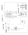
図1において、X線撮影システム10は、X線発生装置11と、X線撮影装置12とからなる。X線発生装置11は、X線源13と、X線源13の駆動を制御する線源制御装置14と、照射スイッチ15とで構成される。X線源13は、X線を放射するX線管13aと、X線管13aが放射するX線の照射野を限定する照射野限定器(コリメータ)13bとを有する。
In FIG. 1, the X-ray imaging system 10 includes an X-ray generation device 11 and an
X線管13aは、熱電子を放出するフィラメントからなる陰極と、陰極から放出された熱電子が衝突してX線を放射する陽極(ターゲット)とからなる。ターゲットは円板形状をしており、回転により円周軌道上で焦点が移動して、熱電子が衝突する焦点の発熱が分散する回転陽極である。照射野限定器13bは、X線を遮蔽する複数枚の鉛板を井桁状に配置し、X線を透過させる照射開口が中央に形成されたものであり、鉛板の位置を移動することで照射開口の大きさを変化させて、照射野を限定する。 The X-ray tube 13a includes a cathode made of a filament that emits thermoelectrons, and an anode (target) that emits X-rays when the thermoelectrons emitted from the cathode collide. The target has a disk shape, and is a rotating anode in which the focal point moves on a circular orbit by rotation, and the heat generated at the focal point where thermal electrons collide is dispersed. The irradiation field limiter 13b has a plurality of lead plates that shield X-rays arranged in a cross-beam shape, and an irradiation opening that transmits X-rays is formed in the center. By moving the position of the lead plate, The irradiation field is limited by changing the size of the irradiation opening.
線源制御装置14は、X線源13に対して高電圧を供給する高電圧発生器と、X線源13が照射するX線のエネルギースペクトルを決める管電圧、単位時間当たりの照射量を決める管電流、およびX線の照射時間を制御する制御部とからなる。高電圧発生器は、トランスによって入力電圧を昇圧して高圧の管電圧を発生し、高電圧ケーブル16を通じてX線源13に駆動電力を供給する。本例のX線発生装置11は、X線撮影装置12との通信機能を持たないものであり、管電圧、管電流、照射時間といった撮影条件は、線源制御装置14の操作パネルを通じて放射線技師により手動で設定される。
The radiation
照射スイッチ15は、放射線技師によって操作され、線源制御装置14に信号ケーブル17で接続されている。照射スイッチ15は二段階押しのスイッチであり、一段階押しでX線源13のウォームアップを開始させるためのウォームアップ開始信号を発生し、二段階押しでX線源13に照射を開始させるための照射開始信号を発生する。これらの信号は信号ケーブル17を通じて線源制御装置14に入力される。
The
線源制御装置14は、照射スイッチ15からの制御信号に基づいて、X線源13の動作を制御する。ウォームアップ開始信号を受けた場合、線源制御装置14は、ヒータを作動させてフィラメントの予熱を行わせる他、ターゲットの回転を開始させて目標の回転速度に到達させる。ウォームアップに必要な時間は、約200msec〜1500msec程度である。放射線技師は、照射スイッチ15の一段階押しでウォームアップの開始指示を入力した後、ウォームアップに必要な間をおいて二段階押しして照射開始指示を入力する。
The radiation
照射開始信号を受けた場合、線源制御装置14は、X線源13への電力供給を開始するとともに、タイマを作動させてX線の照射時間の計測を開始する。そして、撮影条件で設定された照射時間が経過すると、X線の照射を停止させる。X線の照射時間は、撮影条件に応じて変化するが、静止画撮影の場合には、X線の最大照射時間が約500msec〜約2s程度の範囲に定められている場合が多く、照射時間はこの最大照射時間を上限として設定される。
When receiving the irradiation start signal, the radiation
X線撮影装置12は、電子カセッテ21、撮影台22、撮影制御装置23、およびコンソール24から構成される。電子カセッテ21は、照射検出センサ25と、FPD54(図3および図4参照)と、FPD54を収容する可搬型の筐体29(図3参照)とを備え、X線源13から照射されて被検体Hを透過したX線を受けてX線画像を出力する。電子カセッテ21は、略矩形状で偏平な形状を有し、平面サイズはフイルムカセッテやIPカセッテと略同様の大きさである。
The
照射検出センサ25は、FPD54の撮像領域56(図4参照)の近傍に配置される。照射検出センサ25は、X線の照射を受けてX線の入射量に応じた照射検出信号を出力する。照射検出信号は、USBケーブル26で撮影制御装置23に入力される。撮影制御装置23は、照射検出信号の信号レベルを監視して、X線源13によるX線の照射が開始されたことを検出する。
The
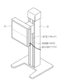
図2にも示すように、撮影台22は、電子カセッテ21が着脱自在に取り付け可能なホルダ27を有し、X線が入射する入射面をX線源13と対向する姿勢で電子カセッテ21を保持する。電子カセッテ21は、筐体29のサイズがフイルムカセッテやIPカセッテと略同様の大きさであるため、フイルムカセッテやIPカセッテ用の既存の撮影台にも取り付け可能である。なお、撮影台22として、被検体Hを立位姿勢で撮影する立位撮影台を例示しているが、被検体Hを臥位姿勢で撮影する臥位撮影台でもよい。また、専用の撮影台にセットするのではなく、電子カセッテ21を被検体Hが仰臥するベッド上に置いたり被検体自身に持たせたりして使用してもよい。
As shown in FIG. 2, the imaging table 22 includes a
図3および図4において、電子カセッテ21にはバッテリ31が取り外し不可に内蔵されている。バッテリ31は、電子カセッテ21の各部を動作させるための電力を供給する。バッテリ31は、薄型の電子カセッテ21内に収まるよう比較的小型のものが使用される。バッテリ31はUSB給電により充電することが可能である。
3 and 4, a
電子カセッテ21には、給電機能を有するUSB(Universal Serial Bus)規格、例えばUSB2.0またはUSB3.0規格のB型ソケット32が設けられている。B型ソケット32は、バッテリ31と反対側の電子カセッテ21の一側面の片側に寄せて配置されている。B型ソケット32は撮影制御装置23と有線接続するために設けられており、B型ソケット32にはUSB2.0または3.0規格のUSBケーブル26(図1、図2も参照)のB型コネクタ33が差し込まれる。USBケーブル26の他端にはA型コネクタ34が設けられており、A型コネクタ34は撮影制御装置23に設けられたA型ソケット35に差し込まれる。
The
B型ソケット32にB型コネクタ33、A型ソケット35にA型コネクタ34をそれぞれ挿してUSBケーブル26を使用した場合、撮影制御装置23との有線通信が可能になるとともに撮影制御装置23から電子カセッテ21に給電(USB2.0の場合は5V、500mA、3.0の場合は5V、900mA)することが可能となる。USBケーブル26を介して供給された電力は、常時全てバッテリ31の充電に用いられる。電子カセッテ21の各部を動作させるための電力は全てバッテリ31で賄われる。
When the B-type connector 33 is inserted into the B-
通信部51には、B型ソケット32が接続されている。通信部51は、B型ソケット32と制御回路52、メモリ53間の画像データを含む各種情報、信号の送受信を媒介する。
A B-
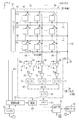
FPD54は、TFTアクティブマトリクス基板を有し、この基板上にX線の入射量に応じた信号電荷を蓄積する複数の画素55を配列してなる撮像領域56と、画素55を駆動して信号電荷の読み出しを制御するゲートドライバ57と、画素55から読み出された信号電荷をデジタルデータに変換して出力する信号処理回路58とを備えている。ゲートドライバ57と信号処理回路58は、制御回路52により動作制御される。複数の画素55は、所定のピッチで二次元にn行(x方向)×m列(y方向)のマトリクス状に配列されている。
The
FPD54は、X線を可視光に変換するシンチレータ(蛍光体)を有し、シンチレータによって変換された可視光を画素55で光電変換する間接変換型である。シンチレータは、画素55が配列された撮像領域56の全面と対向するように配置されている。なお、X線を直接電荷に変換する変換層(アモルファスセレン等)を用いた直接変換型のFPDを用いてもよい。
The
画素55は、可視光の入射によって電荷(電子−正孔対)を発生する光電変換素子であるフォトダイオード59、フォトダイオード59が発生した電荷を蓄積するキャパシタ(図示せず)、およびスイッチング素子として薄膜トランジスタ(TFT)60を備える。
The
フォトダイオード59は、電荷を発生する半導体層(例えばPIN型)とその上下に上部電極および下部電極を配した構造を有している。フォトダイオード59は、下部電極にTFT60が接続され、上部電極にはバイアス線61が接続されており、バイアス線61は撮像領域56内の画素55の行数分(n行分)設けられて結線62に結束されている。結線62はバイアス電源63に繋がれている。結線62、バイアス線61を通じて、バイアス電源63からフォトダイオード59の上部電極にバイアス電圧Vbが印加される。バイアス電圧Vbの印加により半導体層内に電界が生じ、光電変換により半導体層内で発生した電荷(電子−正孔対)は、一方がプラス、他方がマイナスの極性を持つ上部電極と下部電極に移動し、キャパシタに電荷が蓄積される。
The
TFT60は、ゲート電極が走査線64に、ソース電極が信号線65に、ドレイン電極がフォトダイオード59にそれぞれ接続される。走査線64と信号線65は格子状に配線されており、走査線64は撮像領域56内の画素55の行数分(n行分)、信号線65は画素55の列数分(m列分)それぞれ設けられている。走査線64はゲートドライバ57に接続され、信号線65は信号処理回路58に接続される。
The
ゲートドライバ57は、TFT60を駆動することにより、X線の入射量に応じた信号電荷を画素55に蓄積する蓄積動作と、画素55から信号電荷を読み出す読み出し(本読み)動作と、リセット(空読み)動作とを行わせる。制御回路52は、ゲートドライバ57によって実行される上記各動作の開始タイミングを制御する。
The
蓄積動作ではTFT60がオフ状態にされ、その間に画素55に信号電荷が蓄積される。読み出し動作では、ゲートドライバ57から同じ行のTFT60を一斉に駆動するゲートパルスG1〜Gnを順次発生して、走査線64を一行ずつ順に活性化し、走査線64に接続されたTFT60を一行分ずつオン状態とする。画素55のキャパシタに蓄積された電荷は、TFT60がオン状態になると信号線65に読み出されて、信号処理回路58に入力される。
In the accumulation operation, the
フォトダイオード59の半導体層には、X線の入射の有無に関わらず暗電荷が発生する。この暗電荷はバイアス電圧Vbが印加されているためにキャパシタに蓄積される。画素55において発生する暗電荷は、画像データに対してはノイズ成分となるので、これを除去するためにリセット動作が行われる。リセット動作は、画素55において発生する暗電荷を、信号線65を通じて掃き出す動作である。
Dark charges are generated in the semiconductor layer of the
リセット動作は、例えば、一行ずつ画素55をリセットする順次リセット方式で行われる。順次リセット方式では、信号電荷の読み出し動作と同様、ゲートドライバ57から走査線64に対してゲートパルスG1〜Gnを順次発生して、画素55のTFT60を一行ずつオン状態にする。TFT60がオン状態になっている間、画素55から暗電荷が信号線65を通じて積分アンプ66に流れる。リセット動作では、読み出し動作と異なり、マルチプレクサ(MUX)67による積分アンプ66に蓄積された電荷の読み出しは行われず、各ゲートパルスG1〜Gnの発生と同期して、制御回路52からリセットパルスRSTが出力され、積分アンプ66がリセットされる。
For example, the reset operation is performed by a sequential reset method in which the
順次リセット方式に代えて、配列画素の複数行を一グループとしてグループ内で順次リセットを行い、グループ数分の行の暗電荷を同時に掃き出す並列リセット方式や、全行にゲートパルスを入れて全画素の暗電荷を同時に掃き出す全画素リセット方式を用いてもよい。並列リセット方式や全画素リセット方式によりリセット動作を高速化することができる。 Instead of the sequential reset method, multiple rows of array pixels are grouped as a group, and the reset is performed sequentially within the group, and the dark charge of the number of rows in the group is simultaneously discharged. An all-pixel reset method that simultaneously sweeps out the dark charges may be used. The reset operation can be speeded up by a parallel reset method or an all-pixel reset method.
信号処理回路58は、積分アンプ66、MUX67、およびA/D変換器68等を備え、電源69から駆動電力が供給される。積分アンプ66は、各信号線65に対して個別に接続される。積分アンプ66は、オペアンプとオペアンプの入出力端子間に接続されたキャパシタとからなり、信号線65はオペアンプの一方の入力端子に接続される。積分アンプ66のもう一方の入力端子はグランド(GND)に接続される。積分アンプ66は、信号線65から入力される電荷を積算し、電圧信号D1〜Dmに変換して出力する。各列の積分アンプ66の出力端子には、増幅器70、サンプルホールド(S/H)部71を介してMUX67が接続される。MUX67の出力側には、A/D変換器68が接続される。
The
MUX67は、パラレルに接続される複数の積分アンプ66から順に一つの積分アンプ66を選択し、選択した積分アンプ66から出力される電圧信号D1〜DmをシリアルにA/D変換器68に入力する。A/D変換器68は、入力された電圧信号D1〜Dmをデジタルデータに変換して、電子カセッテ21の筐体29に内蔵されるメモリ53に出力する。なお、MUX67とA/D変換器68の間に増幅器を接続してもよい。
The
MUX67によって積分アンプ66から一行分の電圧信号D1〜Dmが読み出されると、制御回路52は、積分アンプ66に対してリセットパルスRSTを出力し、積分アンプ66のリセットスイッチ66aをオンする。これにより、積分アンプ66に蓄積された一行分の信号電荷がリセットされる。積分アンプ66がリセットされると、ゲートドライバ57から次の行のゲートパルスが出力され、次の行の画素55の信号電荷の読み出しを開始させる。これらの動作を順次繰り返して全行の画素55の信号電荷を読み出す。
When the voltage signal D1 to Dm for one row is read from the integrating
全行の読み出しが完了すると、一画面分のX線画像を表す画像データがメモリ53に記録される。この画像データは、メモリ53から読み出され、通信部51を通じて撮影制御装置23に出力される。こうして被検体HのX線画像が検出される。
When the reading of all rows is completed, image data representing an X-ray image for one screen is recorded in the
FPD54ではリセット動作を繰り返し行いつつ、照射検出センサ25でX線の照射開始を検出している。照射検出センサ25によりX線の照射開始が検出されると、制御回路52は、FPD54の動作をリセット動作から蓄積動作へ移行させる。制御回路52は、蓄積動作を開始してからの経過時間をタイマにより計時する。そして、経過時間が撮影条件で設定された時間に達したら、FPD54を蓄積動作から読み出し動作に移行させる。
In the
撮影制御装置23は、USBケーブル26による有線方式により電子カセッテ21と通信可能に接続されており、電子カセッテ21を制御する。具体的には、電子カセッテ21に対して撮影条件を送信して、FPD54の信号処理の条件(増幅器70のゲイン等)を設定させるとともに、FPD54の前記各動作を間接的に制御し、また、電子カセッテ21からの画像データをコンソール24に送信する。
The imaging control device 23 is communicably connected to the
図1において、撮影制御装置23は、装置を統括的に制御するCPU23aと、電子カセッテ21とUSBケーブル26による有線方式により通信するとともに、コンソール24と通信ケーブル28を介して通信する通信部23bと、メモリ23cとを有する。通信部23b、メモリ23cはCPU23aに接続されている。メモリ23cには、CPU23aが実行する制御プログラムが格納される。
In FIG. 1, the imaging control device 23 communicates with a
コンソール24は、撮影制御装置23に対して撮影条件を送信するとともに、撮影制御装置23から送信されるX線画像のデータに対してオフセット補正やゲイン補正等の各種画像処理を施す。画像処理済みのX線画像はコンソール24のディスプレイに表示される他、そのデータがコンソール24内のハードディスクやメモリ、あるいはコンソール24とネットワーク接続された画像蓄積サーバといったデータストレージデバイスに格納される。 The console 24 transmits imaging conditions to the imaging control device 23 and performs various image processing such as offset correction and gain correction on the X-ray image data transmitted from the imaging control device 23. In addition to being displayed on the display of the console 24, the processed X-ray image is stored in a data storage device such as a hard disk or memory in the console 24 or an image storage server connected to the console 24 via a network.
コンソール24は、患者の性別、年齢、撮影部位、撮影目的といった情報が含まれる検査オーダの入力を受け付けて、検査オーダをディスプレイに表示する。検査オーダは、HIS(病院情報システム)やRIS(放射線情報システム)といった患者情報や放射線検査に係る検査情報を管理する外部システムから入力されるか、放射線技師により手動入力される。放射線技師は、検査オーダの内容をディスプレイで確認し、その内容に応じた撮影条件をコンソール24の操作画面を通じて入力する。 The console 24 receives an input of an examination order including information such as the patient's sex, age, imaging region, and imaging purpose, and displays the examination order on the display. The examination order is input from an external system that manages patient information such as HIS (Hospital Information System) and RIS (Radiation Information System) and examination information related to radiation examination, or is manually input by a radiographer. The radiologist confirms the contents of the examination order on the display, and inputs imaging conditions corresponding to the contents through the operation screen of the console 24.
以下、上記構成による作用について説明する。X線撮影システム10で撮影を行う場合には、まず、撮影台22にセットされた電子カセッテ21の高さを調節して、被検体Hの撮影部位と位置を合わせる。また、電子カセッテ21の高さおよび撮影部位の大きさに応じて、X線源13の高さや照射野の大きさを調整する。次いで電子カセッテ21の電源を投入する。続いてコンソール24から撮影条件を入力し、撮影制御装置23を介して電子カセッテ21に撮影条件を設定する。また、線源制御装置14にも撮影条件を設定する。
Hereinafter, the operation of the above configuration will be described. When imaging with the X-ray imaging system 10, first, the height of the
以上の撮影準備が完了すると、放射線技師によって照射スイッチ15が一段階押しされる。これにより線源制御装置14にウォームアップ開始信号が送信されて、X線源13のウォームアップが開始される。所定時間経過後に照射スイッチ15が二段階押しされて線源制御装置14に照射開始信号が送信され、X線の照射が開始される。
When the above preparation for photographing is completed, the
FPD54ではリセット動作が行われつつ照射検出センサ25でX線の照射が開始されたか否かが検出される。X線の照射開始が検出されると、制御回路52は、全てのTFT60をオフ状態にして蓄積動作に移行させる。線源制御装置14は、撮影条件で設定された照射時間が経過するとX線の照射を停止する。また、FPD54も撮影条件で設定された照射時間に相当する所定時間経過後、蓄積動作を終了して、読み出し動作へ移行する。読み出し動作では、先頭行から順に一行ずつ画素55に蓄積された信号電荷が読み出され、これが一画面分のX線画像データとしてメモリ53に記録される。読み出し動作後、FPD54はリセット動作を再開する。
The
メモリ53の画像データはUSBケーブル26で撮影制御装置23に送信され、さらに撮影制御装置23からコンソール24に送信される。画像データはコンソール24でオフセット補正、ゲイン補正等の各種画像処理を施された後、コンソール24のディスプレイに表示されたりデータストレージデバイスに格納される。
The image data in the
電子カセッテ21の各部にはバッテリ31から電力が供給される。バッテリ31はUSBケーブル26で給電される電力により充電される。また、電子カセッテ21と撮影制御装置23の間の信号通信はUSBケーブル26で行われる。専用のケーブルを用いた場合、ケーブルやコネクタが破損するとメーカー取り寄せとなり時間が掛かり、新しいケーブルが届くまで撮影を行うことができないという問題があるが、汎用のUSBケーブル26は最寄りの電器店ですぐに手に入れることができ、また比較的廉価であるので、ユーザの利便性を高めることができる。
Power is supplied from the
USBケーブル26で給電される電力をバッテリ31の充電に用いるため、充電用の端子やACアダプタを電子カセッテ21に用意する必要がない。また、USBケーブル26で給電される電力をバッテリ31の充電専用とし、電子カセッテ21の各部への給電は全てバッテリ31で賄うので、比較的大電力が必要な撮影動作を支障なく行うことができる。
Since the power supplied by the
上記実施形態では、USBケーブル26で給電される電力をバッテリ31の充電専用としているが、USBケーブル26で給電される電力を電子カセッテ21の各部に供給してもよい。但し、USBケーブル26で給電される電力は比較的小さいため、その電力で確実に動作する部分に限られる。
In the above embodiment, the power supplied by the
例えば、電子カセッテ21の非使用時は通信機能(通信部51、制御回路52)のみに給電し、他の各部への給電を停止して電力消費量を抑えるスリープモードで動作させ、この際の電力をバッテリ31ではなくUSBケーブル26で給電される電力で賄う。そして、撮影制御装置23から撮影条件が入力されたことを契機にUSBケーブル26からバッテリ31に電力の供給源を切り替え、通信機能以外の各部にもバッテリ31から給電を行ってfpd54等を動作させ、直ちにX線画像の出力が可能な撮影準備モードにスリープモードから移行する。撮影準備モードではUSBケーブル26で給電される電力は上記実施形態と同様バッテリ31の充電に使用される。スリープモードでバッテリ31を使用しない分、バッテリ31の電力消費量を節約することができる。
For example, when the
USBケーブル26で給電する他に、B型ソケット32に差し込まれるB型コネクタを有するクレードルに電子カセッテ21の筐体29をセットして、クレードルを介してバッテリ31を充電してもよい。あるいは電子カセッテ21に蓋を設け、バッテリ31を外部に取り外し可能とし、充電器でバッテリ31を充電してもよい。このようにUSBケーブル26で給電する以外のバッテリ31の充電の手だてを設け、電子カセッテ21またはバッテリ31を何台か用意しておけば、何回か連続してX線撮影を行ってバッテリ31の残量が急激に減り、USBケーブル26による充電では追いつかない事態となっても、満充電の電子カセッテ21またはバッテリ31に交換して撮影を続行することができる。
In addition to supplying power with the
バッテリ31の残量を検知し、バッテリ31の残量が使用限界値に近い第一の所定値以下のときはUSBケーブル26で給電される電力でバッテリ31を充電し、バッテリ31の残量が満充電に近い第二の所定値以上の場合は、USBケーブル26で給電される電力を装置各部への給電に振り分けてもよい。
When the remaining amount of the
USBケーブル26の接続機能に加えて、メーカー純正の専用ケーブルの接続機能を備えていてもよい。普段バッテリ31は使用せずに専用のケーブルを使用し、外部商用電源からの電力供給と信号通信を行い、専用のケーブルが破損したときに緊急避難的にUSBケーブル26を用いればよい。この場合は専用のケーブルが接続されたかUSBケーブル26が接続されたかを検知する機構を設け、検知結果に応じて外部商用電源からの電力を使用するかバッテリ31を使用するかを切り替える。
In addition to the connection function of the
なお、本発明に係るX線撮影システムは、上記実施形態に限らず、本発明の要旨を逸脱しない限り種々の構成を採り得ることはもちろんである。 It should be noted that the X-ray imaging system according to the present invention is not limited to the above-described embodiment, and various configurations can be adopted without departing from the gist of the present invention.
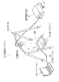
X線撮影システムは病院の撮影室に据え置かれるタイプに限らず、回診車に搭載されるタイプや、X線源82、線源制御装置83、電子カセッテ84、撮影制御装置23とコンソール24の機能を担うノートパソコン85等を事故、災害等の緊急医療対応が必要な現場や在宅診療を受ける患者の自宅に持ち運んでX線撮影を行うことが可能な図5に示す可搬型のシステム81に適用してもよい。 The X-ray imaging system is not limited to the type installed in the imaging room of the hospital, but the type installed in the round-trip car, the functions of the X-ray source 82, the radiation source controller 83, the electronic cassette 84, the imaging controller 23, and the console 24. It can be applied to the portable system 81 shown in FIG. 5 where X-rays can be taken by taking the laptop PC 85, etc., responsible for medical care, to the site where emergency medical treatment is required, such as an accident or disaster, or to the home of a patient receiving home medical care. May be.
この場合、ノートパソコン85に標準装備されるUSBのA型ソケットにUSBケーブル86のA型コネクタを、電子カセッテ84のB型ソケットにUSBケーブル86のB型コネクタをそれぞれ差し込んで電子カセッテ84とノートパソコン85を接続する。なお、符号87は照射スイッチ、符号88はX線源82を懸下保持する保持具である。
In this case, the A-type connector of the USB cable 86 is inserted into the USB-A socket provided as standard on the notebook computer 85, and the B-type connector of the USB cable 86 is inserted into the B-type socket of the electronic cassette 84, respectively. Connect the PC 85.
可搬型のシステムの場合、従来の専用のケーブルやコネクタが破損した場合は出先で立ち往生してしまう。また、可搬型のシステムでは電子カセッテをベッド上に置いたり被検体自身に持たせたりして使用する機会が増えるため、据え置き型と比べてケーブルやコネクタが破損する確率も高い。従って、USBケーブルによる給電および信号通信を可搬型のシステムに適用することで、より優れた効果を発揮することができる。 In the case of a portable system, when a conventional dedicated cable or connector is damaged, it gets stuck at the destination. In portable systems, there are more opportunities to use an electronic cassette placed on a bed or the subject itself, so there is a higher probability that cables and connectors will be damaged compared to a stationary system. Therefore, by applying power supply and signal communication using a USB cable to a portable system, a more excellent effect can be exhibited.
X線源の中には、陽極が回転しない固定陽極型のものや、予熱が不要な冷陰極型の線源等、ウォームアップが不要なものもある。このため、照射スイッチとしては照射開始信号を発生する機能のみを有するものでもよい。また、ウォームアップが必要なX線源の場合でも、照射スイッチから線源制御装置に対して照射開始信号を入力し、線源制御装置が照射開始信号に基づいてウォームアップを開始させ、ウォームアップ終了後、照射を開始させるようにすれば、照射スイッチにウォームアップ開始信号を発生する機能を設ける必要もない。 Some X-ray sources do not require warm-up, such as a fixed anode type in which the anode does not rotate and a cold cathode type source that does not require preheating. For this reason, the irradiation switch may have only a function of generating an irradiation start signal. Even in the case of an X-ray source that requires warm-up, an irradiation start signal is input from the irradiation switch to the radiation source controller, and the radiation source controller starts warm-up based on the irradiation start signal. If irradiation is started after completion, it is not necessary to provide a function for generating a warm-up start signal in the irradiation switch.
上記実施形態では、電子カセッテと撮影制御装置を別体で構成した例で説明したが、撮影制御装置の機能を電子カセッテの制御回路に内蔵する等、電子カセッテと撮影制御装置を一体化してもよい。また、コンソールで画像処理を行うとしているが、撮影制御装置で行ってもよい。さらに、接続方式が有線の一通りしかない電子カセッテを例示したが、電子カセッテにアンテナを設けて撮影制御装置との間の無線通信を可能としてもよい。 In the above-described embodiment, the electronic cassette and the imaging control device are described as separate components. Good. In addition, although image processing is performed by the console, it may be performed by a photographing control device. Furthermore, although an electronic cassette having only one wired connection method has been illustrated, an antenna may be provided on the electronic cassette to enable wireless communication with the imaging control apparatus.
上記実施形態では、汎用のケーブルとしてUSBケーブルの例を記載したが、それ以外にもIEEE1394に準拠した、例えばオーディオ機器に使用されるケーブル等でもよい。要するに一般的な家電量販店等で労せずして手に入り、且つ電力供給の機能を有するケーブルであれば、USBケーブルに限らず汎用性のあるケーブルとして如何なるものも採用することができる。 In the above-described embodiment, an example of a USB cable is described as a general-purpose cable. However, other than that, for example, a cable that is compliant with IEEE1394 and used for an audio device may be used. In short, any cable can be used as a general-purpose cable, not limited to a USB cable, as long as it is a cable that can be obtained without effort at a general consumer electronics retailer and has a power supply function.
本発明は、X線に限らず、γ線等の他の放射線を使用する撮影システムにも適用することができる。 The present invention can be applied not only to X-rays but also to imaging systems that use other radiation such as gamma rays.
10、81 X線撮影システム
11 X線発生装置
12 X線撮影装置
21、84 電子カセッテ
23 撮影制御装置
24 コンソール
26、86 USBケーブル
29 筐体
31 バッテリ
32、33 B型ソケット、B型コネクタ
34、35 A型コネクタ、A型ソケット
51 通信部
52 制御回路
54 FPD
55 画素
58 信号処理回路
85 ノートパソコン
DESCRIPTION OF SYMBOLS 10, 81 X-ray imaging system 11
55
Claims (9)
前記放射線画像検出器を収容する筐体と、
前記筐体に設けられたソケットと、
前記ソケットおよび外部制御装置に設けられたソケットにコネクタ接続される、給電機能を有する汎用規格のケーブルと、
装置各部に電力を供給するバッテリとを備え、
前記ケーブルを介して外部制御装置との間の信号通信を行うとともに、前記ケーブルで給電される電力で前記バッテリを充電することを特徴とする可搬型の放射線画像検出装置。 A radiological image detector having a plurality of pixels that receive radiation emitted from a radiation source and accumulate signal charges;
A housing for housing the radiation image detector;
A socket provided in the housing;
A universal standard cable having a power feeding function, connected to the socket and a socket provided in the external control device,
A battery for supplying power to each part of the device,
A portable radiographic image detection apparatus that performs signal communication with an external control device via the cable and charges the battery with electric power fed by the cable.
該一部を前記ケーブルで給電される電力で動作させることを特徴とする請求項4に記載の可搬型の放射線画像検出装置。 It has a sleep mode that supplies power to only a part of each part of the device,
The portable radiation image detection apparatus according to claim 4, wherein the part is operated by electric power supplied by the cable.
前記放射線画像検出器を収容する筐体と、
前記筐体に設けられ、外部制御装置と接続するためのケーブルが接続される汎用規格のソケットと、
装置各部に電力を供給するバッテリとを備え、
前記ケーブルを介して外部制御装置との間の信号通信を行うとともに、前記ケーブルで給電される電力で前記バッテリを充電することを特徴とする可搬型の放射線画像検出装置。 A radiological image detector having a plurality of pixels that receive radiation emitted from a radiation source and accumulate signal charges;
A housing for housing the radiation image detector;
A general-purpose standard socket that is provided in the housing and to which a cable for connecting to an external control device is connected;
A battery for supplying power to each part of the device,
A portable radiographic image detection apparatus that performs signal communication with an external control device via the cable and charges the battery with electric power fed by the cable.
Priority Applications (2)
| Application Number | Priority Date | Filing Date | Title |
|---|---|---|---|
| JP2011074281A JP2012208337A (en) | 2011-03-30 | 2011-03-30 | Portable radiation image detection device |
| CN2012101119080A CN102727227A (en) | 2011-03-30 | 2012-02-28 | Movable radioactive rays image detection device |
Applications Claiming Priority (1)
| Application Number | Priority Date | Filing Date | Title |
|---|---|---|---|
| JP2011074281A JP2012208337A (en) | 2011-03-30 | 2011-03-30 | Portable radiation image detection device |
Publications (1)
| Publication Number | Publication Date |
|---|---|
| JP2012208337A true JP2012208337A (en) | 2012-10-25 |
Family
ID=46984041
Family Applications (1)
| Application Number | Title | Priority Date | Filing Date |
|---|---|---|---|
| JP2011074281A Abandoned JP2012208337A (en) | 2011-03-30 | 2011-03-30 | Portable radiation image detection device |
Country Status (2)
| Country | Link |
|---|---|
| JP (1) | JP2012208337A (en) |
| CN (1) | CN102727227A (en) |
Cited By (1)
| Publication number | Priority date | Publication date | Assignee | Title |
|---|---|---|---|---|
| JP2019051335A (en) * | 2018-10-26 | 2019-04-04 | キヤノン株式会社 | X-ray imaging apparatus and control method for X-ray imaging apparatus |
Families Citing this family (2)
| Publication number | Priority date | Publication date | Assignee | Title |
|---|---|---|---|---|
| JP5270790B1 (en) * | 2012-05-30 | 2013-08-21 | 富士フイルム株式会社 | Radiation image capturing apparatus, radiation image capturing system, control program for radiation image capturing apparatus, and control method for radiation image capturing apparatus |
| JP6397208B2 (en) * | 2014-04-09 | 2018-09-26 | キヤノン株式会社 | Radiographic imaging apparatus and radiographic imaging system |
Citations (4)
| Publication number | Priority date | Publication date | Assignee | Title |
|---|---|---|---|---|
| JP2006208305A (en) * | 2005-01-31 | 2006-08-10 | Konica Minolta Medical & Graphic Inc | Radiographical image detector and radiographical image photographing system |
| JP2007333380A (en) * | 2004-09-16 | 2007-12-27 | Konica Minolta Medical & Graphic Inc | Radiation detector |
| JP2011045439A (en) * | 2009-08-25 | 2011-03-10 | Fujifilm Corp | Radiographic image capturing device, radiographic image capturing system, and radiographic image capturing method |
| JP2011059058A (en) * | 2009-09-14 | 2011-03-24 | Fujifilm Corp | Radiographic imaging device |
-
2011
- 2011-03-30 JP JP2011074281A patent/JP2012208337A/en not_active Abandoned
-
2012
- 2012-02-28 CN CN2012101119080A patent/CN102727227A/en active Pending
Patent Citations (4)
| Publication number | Priority date | Publication date | Assignee | Title |
|---|---|---|---|---|
| JP2007333380A (en) * | 2004-09-16 | 2007-12-27 | Konica Minolta Medical & Graphic Inc | Radiation detector |
| JP2006208305A (en) * | 2005-01-31 | 2006-08-10 | Konica Minolta Medical & Graphic Inc | Radiographical image detector and radiographical image photographing system |
| JP2011045439A (en) * | 2009-08-25 | 2011-03-10 | Fujifilm Corp | Radiographic image capturing device, radiographic image capturing system, and radiographic image capturing method |
| JP2011059058A (en) * | 2009-09-14 | 2011-03-24 | Fujifilm Corp | Radiographic imaging device |
Cited By (1)
| Publication number | Priority date | Publication date | Assignee | Title |
|---|---|---|---|---|
| JP2019051335A (en) * | 2018-10-26 | 2019-04-04 | キヤノン株式会社 | X-ray imaging apparatus and control method for X-ray imaging apparatus |
Also Published As
| Publication number | Publication date |
|---|---|
| CN102727227A (en) | 2012-10-17 |
Similar Documents
| Publication | Publication Date | Title |
|---|---|---|
| JP5208186B2 (en) | Radiation image detection apparatus and drive control method thereof | |
| JP5544383B2 (en) | Radiation image detection apparatus and radiography system | |
| JP5587356B2 (en) | Radiation imaging system, radiation imaging system drive control method, drive control program, and radiation image detection apparatus | |
| JP2012118312A (en) | Radiation image detector and drive control method thereof | |
| JP5438714B2 (en) | Radiography equipment | |
| JP2012100807A (en) | Radiation image detecting device and method for driving and controlling the same | |
| US8130909B2 (en) | Radiographic imaging device, image processing device | |
| US8546777B2 (en) | Radiographic image capturing device | |
| US20100207032A1 (en) | Radiographic image capture system, radiation generation device, image capture control device and radiographic image capture device | |
| JP5500933B2 (en) | Radiographic imaging apparatus, radiographic imaging system, and program | |
| JP5473854B2 (en) | Radiography apparatus and radiation imaging system | |
| JP2012119956A (en) | Radiation image detector | |
| JP5623334B2 (en) | Electronic cassette and radiation imaging apparatus | |
| JP2012239814A (en) | Radiographic apparatus | |
| JP6027203B2 (en) | Portable radiological image detection device | |
| JP5496063B2 (en) | Radiation imaging apparatus, drive control method thereof, and radiation imaging system | |
| JP2012208337A (en) | Portable radiation image detection device | |
| JP5660951B2 (en) | Portable radiological image detection device | |
| JP5660871B2 (en) | Radiation image detection apparatus and radiation irradiation start detection method | |
| JP6186477B2 (en) | Radiation image detection apparatus and radiation irradiation start detection method | |
| JP2009180537A (en) | Cradle for use with radiation conversion device | |
| JP5964931B2 (en) | Radiation image detection apparatus and radiation irradiation start detection method | |
| JP2013130539A (en) | Radiation image photography device, radiation image photography system, radiation image photography method, and radiation image photography program | |
| JP5660872B2 (en) | Radiation image detection apparatus and radiation irradiation start detection method | |
| JP5728897B2 (en) | Charging system |
Legal Events
| Date | Code | Title | Description |
|---|---|---|---|
| A977 | Report on retrieval |
Free format text: JAPANESE INTERMEDIATE CODE: A971007 Effective date: 20130307 |
|
| A131 | Notification of reasons for refusal |
Free format text: JAPANESE INTERMEDIATE CODE: A131 Effective date: 20130313 |
|
| A762 | Written abandonment of application |
Free format text: JAPANESE INTERMEDIATE CODE: A762 Effective date: 20130422 |