JP2012208207A - Light source device, projector, and incorporating method for light source device - Google Patents
Light source device, projector, and incorporating method for light source device Download PDFInfo
- Publication number
- JP2012208207A JP2012208207A JP2011072140A JP2011072140A JP2012208207A JP 2012208207 A JP2012208207 A JP 2012208207A JP 2011072140 A JP2011072140 A JP 2011072140A JP 2011072140 A JP2011072140 A JP 2011072140A JP 2012208207 A JP2012208207 A JP 2012208207A
- Authority
- JP
- Japan
- Prior art keywords
- light source
- holding body
- source device
- projector
- hole
- Prior art date
- Legal status (The legal status is an assumption and is not a legal conclusion. Google has not performed a legal analysis and makes no representation as to the accuracy of the status listed.)
- Granted
Links
Images


Classifications
-
- G—PHYSICS
- G03—PHOTOGRAPHY; CINEMATOGRAPHY; ANALOGOUS TECHNIQUES USING WAVES OTHER THAN OPTICAL WAVES; ELECTROGRAPHY; HOLOGRAPHY
- G03B—APPARATUS OR ARRANGEMENTS FOR TAKING PHOTOGRAPHS OR FOR PROJECTING OR VIEWING THEM; APPARATUS OR ARRANGEMENTS EMPLOYING ANALOGOUS TECHNIQUES USING WAVES OTHER THAN OPTICAL WAVES; ACCESSORIES THEREFOR
- G03B21/00—Projectors or projection-type viewers; Accessories therefor
- G03B21/14—Details
- G03B21/20—Lamp housings
- G03B21/2006—Lamp housings characterised by the light source
- G03B21/2033—LED or laser light sources
-
- G—PHYSICS
- G03—PHOTOGRAPHY; CINEMATOGRAPHY; ANALOGOUS TECHNIQUES USING WAVES OTHER THAN OPTICAL WAVES; ELECTROGRAPHY; HOLOGRAPHY
- G03B—APPARATUS OR ARRANGEMENTS FOR TAKING PHOTOGRAPHS OR FOR PROJECTING OR VIEWING THEM; APPARATUS OR ARRANGEMENTS EMPLOYING ANALOGOUS TECHNIQUES USING WAVES OTHER THAN OPTICAL WAVES; ACCESSORIES THEREFOR
- G03B21/00—Projectors or projection-type viewers; Accessories therefor
- G03B21/14—Details
- G03B21/20—Lamp housings
- G03B21/2086—Security or safety means in lamp houses
-
- Y—GENERAL TAGGING OF NEW TECHNOLOGICAL DEVELOPMENTS; GENERAL TAGGING OF CROSS-SECTIONAL TECHNOLOGIES SPANNING OVER SEVERAL SECTIONS OF THE IPC; TECHNICAL SUBJECTS COVERED BY FORMER USPC CROSS-REFERENCE ART COLLECTIONS [XRACs] AND DIGESTS
- Y10—TECHNICAL SUBJECTS COVERED BY FORMER USPC
- Y10T—TECHNICAL SUBJECTS COVERED BY FORMER US CLASSIFICATION
- Y10T29/00—Metal working
- Y10T29/49—Method of mechanical manufacture
- Y10T29/49764—Method of mechanical manufacture with testing or indicating
- Y10T29/49778—Method of mechanical manufacture with testing or indicating with aligning, guiding, or instruction
- Y10T29/4978—Assisting assembly or disassembly
Landscapes
- Physics & Mathematics (AREA)
- General Physics & Mathematics (AREA)
- Engineering & Computer Science (AREA)
- Computer Security & Cryptography (AREA)
- Optics & Photonics (AREA)
- Projection Apparatus (AREA)
- Transforming Electric Information Into Light Information (AREA)
- Non-Portable Lighting Devices Or Systems Thereof (AREA)
Abstract
Description
本発明は、プロジェクタに組み込む光源装置、プロジェクタ、及びこの光源装置の組込み方法に関する。 The present invention relates to a light source device incorporated in a projector, a projector, and a method for incorporating the light source device.
今日、パーソナルコンピュータの画面やビデオ画像、更にメモリカード等に記憶されている画像データによる画像等をスクリーンに投影する画像投影装置としてのデータプロジェクタが多用されている。このプロジェクタは、光源から射出された光をDMD(デジタル・マイクロミラー・デバイス)と呼ばれるマイクロミラー表示素子、又は、液晶板に集光させ、スクリーン上にカラー画像を表示させるものである。 2. Description of the Related Art Today, data projectors are widely used as image projection apparatuses that project a screen of a personal computer, a video image, an image based on image data stored in a memory card or the like onto a screen. This projector focuses light emitted from a light source on a micromirror display element called DMD (digital micromirror device) or a liquid crystal plate, and displays a color image on a screen.
このようなプロジェクタにおいて、従来は高輝度の放電ランプを光源とするものが主流であったが、近年、光源として発光ダイオードやレーザーダイオード、あるいは、有機EL、蛍光体等を用いる種々のプロジェクタの開発が多々なされている。 In the past, projectors using a high-intensity discharge lamp as the light source have been the mainstream. However, in recent years, various projectors using light emitting diodes, laser diodes, organic EL, phosphors, etc. as the light source have been developed. There have been many.
ところで、プロジェクタ内から光源としてのレーザーダイオード等が故意に取り出され、他の用途に転用される、レーザー光に誤って被曝する、等の不具合が生じる虞がある。例えば、特許文献1には、レーザー装置からレーザー共振器を故意に取り外し、レーザー共振器を他の用途に転用するのを防止するレーザー装置が開示されている。 By the way, there is a risk that a laser diode or the like as a light source is intentionally taken out from the projector and diverted to other uses or accidentally exposed to laser light. For example, Patent Document 1 discloses a laser device that intentionally removes a laser resonator from the laser device and prevents the laser resonator from being diverted to other uses.
しかしながら、特許文献1は、レーザー共振器が取り外された場合にそのレーザー共振器の一部が破壊される技術を示すレーザー装置であり、レーザー装置から光源を取り外し困難な構造を示すものではない。 However, Patent Document 1 is a laser device showing a technique in which a part of the laser resonator is broken when the laser resonator is removed, and does not show a structure in which it is difficult to remove a light source from the laser device.
本発明は上述したような従来技術の問題点に鑑みてなされたものであり、製造時に煩雑な工程を行うことなく、簡単な構造で、動作検査に合格したプロジェクタ筐体内の光源装置の光源を他の用途に用いるために取外すことを防止可能なプロジェクタ、光源装置、及びプロジェクタの製造方法を提供することを目的とする。 The present invention has been made in view of the above-described problems of the prior art, and the light source of the light source device in the projector housing that has passed the operation test with a simple structure without performing complicated steps during manufacture. It is an object of the present invention to provide a projector, a light source device, and a projector manufacturing method that can be prevented from being removed for use in other applications.
本発明に係る光源装置は、光源を保持する第1の保持体と、前記第1の保持体に保持された前記光源から射出される光を集光するコリメータレンズを保持する第2の保持体と、を備え、前記第2の保持体と前記第1の保持体とを固定する固定部材により前記第1の保持体と前記第2の保持体が一体とされる光源装置であって、前記第1の保持体から前記第2の保持体側に又は前記第2の保持体から前記第1の保持体側に突出する突出部を有するとともに前記第2の保持体又は前記第1の保持体に前記突出部を受ける切欠き部を備える受け座部を有し、前記突出部に係止部材を挿入する貫通孔を有し、前記係止部材は、棒状の本体部を有して該本体部を前記突出部に設けられた前記貫通孔を貫通させて前記受け座部に設けられた受け穴に先端を挿入し封止剤によりその頭部が埋設されていることを特徴とする。 A light source device according to the present invention includes a first holding body that holds a light source, and a second holding body that holds a collimator lens that collects light emitted from the light source held by the first holding body. And a light source device in which the first holding body and the second holding body are integrated by a fixing member that fixes the second holding body and the first holding body, The second holding body or the first holding body has a protruding portion that protrudes from the first holding body to the second holding body or from the second holding body to the first holding body. It has a receiving seat part provided with a notch part which receives a projection part, it has a penetration hole which inserts a locking member in the projection part, and the locking member has a rod-like body part, and this body part is Insert the tip into the receiving hole provided in the receiving seat part through the through hole provided in the protruding part. Characterized in that its head by entering the city sealant is embedded.
また、本発明に係るプロジェクタは、光源装置と、前記光源装置の発する光を同一光軸とする導光光学系と、表示素子と、前記導光光学系により前記同一光軸とされた光を前記表示素子に導く光源側光学系と、前記表示素子により形成される光学像をスクリーンに投影する投影側光学系と、冷却装置と、前記光源装置や前記表示素子及び前記冷却装置を制御するプロジェクタ制御手段と、を備え、前記光源装置が上記本発明に係る上記光源装置であることを特徴とする。 The projector according to the present invention also includes a light source device, a light guide optical system having light emitted from the light source device as the same optical axis, a display element, and light having the same optical axis as the light guide optical system. A light source side optical system that leads to the display element; a projection side optical system that projects an optical image formed by the display element onto a screen; a cooling device; and a projector that controls the light source device, the display element, and the cooling device. Control means, wherein the light source device is the light source device according to the invention.
さらに、本発明に係る光源装置の組込み方法は、光源を保持する第1の保持体と、前記第1の保持体に保持された前記光源から射出される光を集光するコリメータレンズを保持する第2の保持体と、を備え、前記第2の保持体と前記第1の保持体とを固定する固定ネジにより前記第1の保持体と前記第2の保持体が一体とされ、前記第1の保持体から前記第2の保持体側に又は前記第2の保持体から前記第1の保持体側に突出する突出部を有するとともに前記第2の保持体又は前記第1の保持体に前記突出部を受ける切欠き部を備える受け座部を有し、前記突出部に係止部材を挿入する貫通孔を有し、前記係止部材は棒状の本体部を有して該本体部を前記突出部に設けられた貫通孔を貫通させて前記受け座部に設けられた受け穴に先端を挿入し封止剤によりその頭部が埋設されている光源装置を備えたプロジェクタにおける前記光源装置の組込み方法であって、前記コリメータレンズの光軸と前記光源の光軸とを合わせる調整を行ったのち前記固定ネジにより前記第2の保持体と前記第1の保持体とを固定し、又は、前記固定ネジにより前記第2の保持体と前記第1の保持体とを固定したのち前記コリメータレンズの光軸と前記光源の光軸とを合わせる調整を行い、前記第2の保持体と前記第1の保持体とを固定した光源装置をプロジェクタの筐体内に組み込んで、前記プロジェクタの光学特性の調整を行った後、前記係止部材を前記凹穴部に挿入し、前記プロジェクタの総合検査を行った後、前記凹穴部に前記封止剤を充填することを特徴とする。 Furthermore, the method for assembling the light source device according to the present invention holds the first holding body that holds the light source and the collimator lens that collects the light emitted from the light source held by the first holding body. A second holding body, and the first holding body and the second holding body are integrated by a fixing screw that fixes the second holding body and the first holding body. A protrusion that protrudes from one holding body toward the second holding body or from the second holding body toward the first holding body, and protrudes into the second holding body or the first holding body. A receiving seat having a notch for receiving a portion, and a through hole into which the locking member is inserted into the protruding portion, and the locking member has a rod-shaped main body and the main body protrudes from the protrusion Insert the tip into the receiving hole provided in the receiving seat through the through hole provided in the receiving part A method for assembling the light source device in a projector having a light source device whose head is embedded by a sealant, the adjustment being performed after adjusting the optical axis of the collimator lens and the optical axis of the light source The second holding body and the first holding body are fixed by a fixing screw, or the light of the collimator lens is fixed after the second holding body and the first holding body are fixed by the fixing screw. The light source device in which the second holding body and the first holding body are fixed is incorporated in the projector housing to adjust the optical characteristics of the projector. After performing, the said locking member is inserted in the said recessed hole part, and after performing the comprehensive test | inspection of the said projector, the said sealing agent is filled into the said recessed hole part, It is characterized by the above-mentioned.
本発明によれば、製造時に煩雑な工程を行うことなく、簡単な構造で、検査に合格したプロジェクタ筐体内の光源装置の光源を他の用途に用いるために取り外すことを防止可能な、プロジェクタに組み込む光源装置、プロジェクタ、及び光源装置の組込み方法を提供することができる。 According to the present invention, there is provided a projector capable of preventing the light source of the light source device in the projector housing that has passed the inspection from being removed for use in another application with a simple structure without performing a complicated process during manufacture. A light source device to be incorporated, a projector, and a method for incorporating the light source device can be provided.
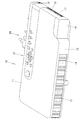
以下、本発明を実施するための形態について述べる。図1は、プロジェクタ10の外観斜視図である。なお、本実施形態において、プロジェクタ10における左右とは投影方向に対しての左右方向を示し、前後とはプロジェクタ10のスクリーン側方向及び光線束の進行方向に対しての前後方向を示す。
Hereinafter, modes for carrying out the present invention will be described. FIG. 1 is an external perspective view of the
そして、プロジェクタ10は、図1に示すように、略直方体形状であって、プロジェクタ筐体の前方の側板とされる正面パネル12の側方に投影口を覆うレンズカバー19を有するとともに、この正面パネル12には複数の吸気孔18を設けている。さらに、図示しないがリモートコントローラからの制御信号を受信するIr受信部を備えている。
As shown in FIG. 1, the
また、筐体の上面パネル11にはキー/インジケータ部37が設けられ、このキー/インジケータ部37には、電源スイッチキーや電源のオン又はオフを報知するパワーインジケータ、投影のオン、オフを切りかえる投影スイッチキー、光源ユニットや表示素子又は制御回路等が過熱したときに報知をする過熱インジケータ等のキーやインジケータが配置されている。
In addition, a key /
さらに、筐体の背面には、背面パネルにUSB端子や画像信号入力用のD−SUB端子、S端子、RCA端子等を設ける入出力コネクタ部及び電源アダプタプラグ等の各種端子20が設けられている。また、背面パネルには、複数の吸気孔が形成されている。なお、図示しない筐体の側板である右側パネル、及び、図1に示した側板である左側パネル15には、各々複数の排気孔17が形成されている。また、左側パネル15の背面パネル近傍の隅部には、吸気孔18も形成されている。さらに、図示しない下面パネルにおける正面、背面、左側及び右側パネルの近傍にも、吸気孔あるいは排気孔が複数形成されている。
In addition, on the rear surface of the housing, there are provided
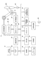
次に、プロジェクタ10のプロジェクタ制御手段について図2のブロック図を用いて述べる。プロジェクタ制御手段は、制御部38、入出力インターフェース22、画像変換部23、表示エンコーダ24、表示駆動部26等から構成され、入出力コネクタ部21から入力された各種規格の画像信号は、入出力インターフェース22、システムバス(SB)を介して画像変換部23で表示に適した所定のフォーマットの画像信号に統一するように変換された後、表示エンコーダ24に出力される。
Next, projector control means of the
また、表示エンコーダ24は、入力された画像信号をビデオRAM25に展開記憶させた上でこのビデオRAM25の記憶内容からビデオ信号を生成して表示駆動部26に出力する。
The
表示駆動部26は、表示素子制御手段として機能するものであり、表示エンコーダ24から出力された画像信号に対応して適宜フレームレートで空間的光変調素子(SOM)である表示素子51を駆動するものであり、光源ユニット60から射出された光線束を、導光光学系を介して表示素子51に照射することにより、表示素子51の反射光で光像を形成し、後述する投影側光学系を介して図示しないスクリーンに画像を投影表示する。なお、この投影側光学系の可動レンズ群235は、レンズモータ45によりズーム調整やフォーカス調整のための駆動が行われる。
The
また、画像圧縮伸長部31は、画像信号の輝度信号及び色差信号をADCT及びハフマン符号化等の処理によりデータ圧縮して着脱自在な記録媒体とされるメモリカード32に順次書き込む記録処理を行う。さらに、画像圧縮伸長部31は、再生モード時にメモリカード32に記録された画像データを読み出し、一連の動画を構成する個々の画像データを1フレーム単位で伸長し、この画像データを、画像変換部23を介して表示エンコーダ24に出力し、メモリカード32に記憶された画像データに基づいて動画等の表示を可能とする処理を行う。
The image compression /
制御部38は、プロジェクタ10内の各回路の動作制御を司るものであって、CPUや各種セッティング等の動作プログラムを固定的に記憶したROM及びワークメモリとして使用されるRAM等により構成されている。
The
筐体の上面パネル11に設けられるメインキー及びインジケータ等により構成されるキー/インジケータ部37の操作信号は、直接に制御部38に送出され、リモートコントローラからのキー操作信号は、Ir受信部35で受信され、Ir処理部36で復調されたコード信号が制御部38に出力される。
An operation signal of a key /
なお、制御部38にはシステムバス(SB)を介して音声処理部47が接続されている。この音声処理部47は、PCM音源等の音源回路を備えており、投影モード及び再生モード時には音声データをアナログ化し、スピーカ48を駆動して拡声放音させる。
Note that an
また、制御部38は、光源制御手段としての光源制御回路41を制御しており、この光源制御回路41は、画像生成時に要求される所定波長帯域の光が光源ユニット60から射出されるように、光源ユニット60の励起光照射装置、赤色光源装置、及び青色光源装置の発光を個別に制御する。
Further, the
さらに、制御部38は、冷却ファン駆動制御回路43に光源ユニット60等に設けた複数の温度センサによる温度検出を行わせ、この温度検出の結果から冷却ファンの回転速度を制御させている。また、制御部38は、冷却ファン駆動制御回路43にタイマー等によりプロジェクタ本体の電源OFF後も冷却ファンの回転を持続させる、あるいは、温度センサによる温度検出の結果によってはプロジェクタ本体の電源をOFFにする等の制御も行う。
Further, the
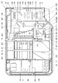
次に、このプロジェクタ10の内部構造について述べる。図3は、プロジェクタ10の内部構造を示す平面模式図である。プロジェクタ10は、図3に示すように、右側パネル14の近傍に制御回路基板241を備えている。この制御回路基板241は、電源回路ブロックや光源制御ブロック等を備えてなる。また、プロジェクタ10は、制御回路基板241の側方、つまり、プロジェクタ筐体の略中央部分に光源ユニット60を備えている。さらに、プロジェクタ10は、光源ユニット60と左側パネル15との間に光学系ユニット160を備えている。
Next, the internal structure of the
光源ユニット60は、プロジェクタ筐体の左右方向における略中央部分であって背面パネル13近傍に配置される励起光照射装置70と、この励起光照射装置70から射出される光線束の光軸上であって正面パネル12の近傍に配置される蛍光発光装置100と、この蛍光発光装置100から射出される光線束と平行となるように正面パネル12の近傍に配置される青色光源装置300と、励起光照射装置70と蛍光発光装置100との間に配置される赤色光源装置120と、蛍光発光装置100からの射出光や赤色光源装置120からの射出光、青色光源装置300からの射出光の光軸が夫々同一の光軸となるように変換して各色光を所定の一面であるライトトンネル175の入射口に導光する導光光学系140と、を備える。
The
励起光照射装置70は、背面パネル13と光軸が平行になるよう配置された励起光源71と、励起光源71からの射出光の光軸を正面パネル12方向に90度変換する反射ミラー群75と、反射ミラー群75で反射した励起光源71からの射出光を集光する集光レンズ78と、励起光源71と右側パネル14との間に配置されたヒートシンク81と、を備える。
The excitation
励起光源71は、3行8列の計24個の青色レーザーダイオードがマトリクス状に配列されており、各青色レーザーダイオードの光軸上には、各青色レーザーダイオードからの射出光を平行光に変換する集光レンズであるコリメータレンズ73が夫々配置されている。また、反射ミラー群75は、複数の反射ミラーが階段状に配列されてなり、励起光源71から射出される光線束の断面積を一方向に縮小して集光レンズ78に射出する。
The
ヒートシンク81と背面パネル13との間には冷却ファン261が配置されており、この冷却ファン261とヒートシンク81とによって励起光源71が冷却される。さらに、反射ミラー群75と背面パネル13との間にも冷却ファン261が配置されており、この冷却ファン261によって反射ミラー群75や集光レンズ78が冷却される。
A cooling
蛍光発光装置100は、正面パネル12と平行となるように、つまり、励起光照射装置70からの射出光の光軸と直交するように配置された蛍光ホイール101と、この蛍光ホイール101を回転駆動するホイールモータ110と、蛍光ホイール101から背面パネル13方向に射出される光線束を集光する集光レンズ群111と、を備える。
The fluorescent
蛍光ホイール101は、円板状の金属基材であって、励起光源71からの射出光を励起光として緑色波長帯域の蛍光発光光を射出する環状の蛍光発光領域が凹部として形成され、励起光を受けて蛍光発光する蛍光板として機能する。また、蛍光発光領域を含む蛍光ホイール101の励起光源71側の表面は、銀蒸着等によってミラー加工されることで光を反射する反射面が形成され、この反射面上に緑色蛍光体の層が敷設されている。
The
そして、蛍光ホイール101の緑色蛍光体層に照射された励起光照射装置70からの射出光は、緑色蛍光体層における緑色蛍光体を励起し、緑色蛍光体から全方位に蛍光発光された光線束は、直接励起光源71側へ、あるいは、蛍光ホイール101の反射面で反射した後に励起光源71側へ射出される。また、蛍光体層の蛍光体に吸収されることなく、金属基材に照射された励起光は、反射面により反射されて再び蛍光体層に入射し、蛍光体を励起することとなる。よって、蛍光ホイール101の凹部の表面を反射面とすることにより、励起光源71から射出される励起光の利用効率を上げることができ、より明るく発光させることができる。
The light emitted from the excitation
なお、蛍光ホイール101の反射面で蛍光体層側に反射された励起光において蛍光体に吸収されることなく励起光源71側に射出された励起光は、後述する第一ダイクロイックミラー141を透過し、蛍光光は第一ダイクロイックミラー141により反射されるため、励起光が外部に射出されることはない。そして、ホイールモータ110と正面パネル12との間には冷却ファン261が配置されており、この冷却ファン261によって蛍光ホイール101が冷却される。
In the excitation light reflected on the phosphor layer side by the reflecting surface of the
赤色光源装置120は、励起光源71と光軸が平行となるように配置された赤色光源121と、赤色光源121からの射出光を集光する集光レンズ群125と、を備える。そして、この赤色光源装置120は、励起光照射装置70からの射出光及び蛍光ホイール101から射出される緑色波長帯域光と光軸が交差するように配置されている。また、赤色光源121は、赤色の波長帯域光を発する半導体発光素子としての赤色発光ダイオードである。さらに、赤色光源装置120は、赤色光源121の右側パネル14側に配置されるヒートシンク130を備える。そして、ヒートシンク130と正面パネル12との間には冷却ファン261が配置されており、この冷却ファン261によって赤色光源121が冷却される。
The red
青色光源装置300は、蛍光発光装置100からの射出光の光軸と平行となるように配置された青色光源301と、青色光源301からの射出光を集光する集光レンズ群305と、を備える。そして、この青色光源装置300は、赤色光源装置120からの射出光と光軸が交差するように配置されている。また、青色光源301は、青色の波長帯域光を発する半導体発光素子としての青色発光ダイオードである。さらに、青色光源装置300は、青色光源301の正面パネル12側に配置されるヒートシンク310を備える。そして、ヒートシンク310と正面パネル12との間には冷却ファン261が配置されており、この冷却ファン261によって青色光源301が冷却される。
The blue
そして、導光光学系140は、赤色、緑色、青色波長帯域の光線束を集光させる集光レンズや、各色波長帯域の光線束の光軸を変換して同一の光軸とさせるダイクロイックミラー等からなる。具体的には、励起光照射装置70から射出される青色波長帯域光及び蛍光ホイール101から射出される緑色波長帯域光の光軸と、赤色光源装置120から射出される赤色波長帯域光の光軸と、が交差する位置に、青色及び赤色波長帯域光を透過し、緑色波長帯域光を反射してこの緑色光の光軸を左側パネル15方向に90度変換する第一ダイクロイックミラー141が配置されている。
The light guide
また、青色光源装置300から射出される青色波長帯域光の光軸と、赤色光源装置120から射出される赤色波長帯域光の光軸と、が交差する位置に、青色波長帯域光を透過し、緑色及び赤色波長帯域光を反射してこの緑色及び赤色光の光軸を背面パネル13方向に90度変換する第二ダイクロイックミラー148が配置されている。そして、第一ダイクロイックミラー141と第二ダイクロイックミラー148との間には、集光レンズが配置されている。さらに、ライトトンネル175の近傍には、ライトトンネル175の入射口に光源光を集光する集光レンズ173が配置されている。
Further, the blue wavelength band light is transmitted at a position where the optical axis of the blue wavelength band light emitted from the blue
光学系ユニット160は、励起光照射装置70の左側方に位置する照明側ブロック161と、背面パネル13と左側パネル15とが交差する位置の近傍に位置する画像生成ブロック165と、導光光学系140と左側パネル15との間に位置する投影側ブロック168と、の3つのブロックによって略コの字状に構成されている。
The
この照明側ブロック161は、光源ユニット60から射出された光源光を画像生成ブロック165が備える表示素子51に導光する光源側光学系170の一部を備えている。この照明側ブロック161が有する光源側光学系170としては、光源ユニット60から射出された光線束を均一な強度分布の光束とするライトトンネル175、ライトトンネル175から射出された光を集光する集光レンズ178、ライトトンネル175から射出された光線束の光軸を画像生成ブロック165方向に変換する光軸変換ミラー181等がある。
The
画像生成ブロック165は、光源側光学系170として、光軸変換ミラー181で反射した光源光を表示素子51に集光させる集光レンズ183と、この集光レンズ183を透過した光線束を表示素子51に所定の角度で照射する照射ミラー185と、を有している。さらに、画像生成ブロック165は、表示素子51とするDMDを備え、この表示素子51と背面パネル13との間には表示素子51を冷却するためのヒートシンク190が配置されて、このヒートシンク190によって表示素子51が冷却される。また、表示素子51の正面近傍には、投影側光学系220としての集光レンズ195が配置されている。
As the light source side
投影側ブロック168は、表示素子51で反射されたオン光をスクリーンに放出する投影側光学系220のレンズ群を有している。この投影側光学系220としては、固定鏡筒に内蔵する固定レンズ群225と可動鏡筒に内蔵する可動レンズ群235とを備えてズーム機能を備えた可変焦点型レンズとされ、レンズモータにより可動レンズ群235を移動させることによりズーム調整やフォーカス調整を可能としている。
The projection-
なお、光源装置における励起光源71は、上述のとおり3行8列の計24個の青色レーザーダイオードがマトリクス状に配列されている。
The
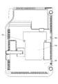
次に、プロジェクタ10の底面側の構造について説明する。図4は、本発明の実施形態に係るプロジェクタ10の底パネル蓋16aが取り付けられた状態を示す底面図である。図5は、本発明の実施形態に係るプロジェクタ10の底パネル蓋16aが取り外された光源装置である励起光照射装置70の露出した状態を示す底面図である。
Next, the structure on the bottom side of the
図4、図5に示すように、プロジェクタ10の筐体の底面パネル16の中央近傍に、励起光照射装置70の位置に合わせて開口部16b、及び底パネル蓋16aが設けられている。詳細には、底面パネル16の開口部16bには、開口部16bに取り付け可能な蓋部である底パネル蓋16aが、ネジ16c、16dにより固定される。この開口部16b及び底パネル蓋16aは、励起光照射装置70の保守を可能とするものである。
As shown in FIGS. 4 and 5, an
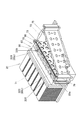
プロジェクタ10の光源装置である励起光照射装置70を説明する。図6は、本発明の実施形態に係る光源装置の底面側からの斜視図である。図7は、本発明の実施形態に係る光源装置の断面図である。尚、励起光照射装置70の底面側及び上面側は、それぞれ図7に示す上側及び下側に対応する。また、図7は、励起光照射装置70の各ネジを通る断面について示している。
An excitation
図6、図7に示すように、励起光照射装置70は、光源としての励起光源71と、励起光源71から射出される光の指向性を高める集光レンズとしてのコリメータレンズ73と、レンズ取付枠74と、コリメータレンズ73を保持する第2の保持体としてのレンズ保持体79と、第1の保持体としての光源保持体80と、押え板89と、を有する。尚、本実施形態の励起光照射装置70は、係止部材であるネジ320を備えるものである。
As shown in FIGS. 6 and 7, the excitation
コリメータレンズ73は、励起光源71である青色レーザーダイオードからの射出光を平行光に変換させる集光レンズである。レンズ取付枠74は、予めコリメータレンズ73と一体とされるものであり、図7に示すように、コリメータレンズ73の周縁に接着剤等で固着される取付枠である。コリメータレンズ73の位置調整は、コリメータレンズ73の周縁を接着剤等で固着されて一体とされるレンズ取付枠74の周縁を押圧して移動させて行うことにより、レンズ自体を傷つけることを防止できる。
The
レンズ保持体79は、耐熱樹脂性の保持部材であり、図7に示したように、複数の孔部79aを有し、集光レンズであるコリメータレンズ73と一体とされたレンズ取付枠74をレンズ枠穴79bに配置して、光軸に対して直交する方向に調整可能範囲で移動可能なように保持する。レンズ保持体79の孔部79aそれぞれには、励起光源71が配置されている。
The
また、レンズ保持体79は、レンズ枠穴79bに配置されたレンズ取付枠74が光軸に沿って下方向に移動しないようにレンズ取付枠74の上部周縁に設けた突出部を受ける構造となっている。そして、調整時にレンズ取付枠74は、光軸に沿って上方向に移動しないように押え板89により、レンズ取付枠74の上部周縁に設けた突出部を上から挟持されている。すなわち、上記構成により、コリメータレンズ73の光軸を調整することが可能である。
Further, the
光源保持体80は、アルミニウム等の放熱部材であり、励起光源71を保持する。詳細には、光源保持体80は、図7に示したように、レンズ保持体79と嵌合するとともにレンズ保持体79との間に励起光源71を保持する。また、光源保持体80とレンズ保持体79とは、励起光源71を保持した状態で、固定部材であるネジ87で固定されることにより一体とされる。光源保持体80の裏面側には、例えば制御部38に電気的に接続されるフレキシブル基板90が配置され、このフレキシブル基板90はリード線端子部92を介して、励起光源71と電気的に接続されている。レンズ保持体79と光源保持体80とにより、励起光源71とコリメータレンズ73とが光軸調整された状態で保持される。
The
次に、本発明の実施形態に係るプロジェクタ10の励起光源71の取り外し防止機構を、図面を参照しながら詳説する。図8は、本発明の実施形態に係る光源装置である励起光照射装置70の要部の拡大断面図である。励起光源71は、光源保持体80とレンズ保持体79の端面79cとの間に励起光源71が保持されている。
Next, a mechanism for preventing removal of the
励起光照射装置70は、第1の保持体としての光源保持体80から第2の保持体であるレンズ保持体79側に、又は、レンズ保持体79から光源保持体80側に突出する突出部80aを有し、レンズ保持体79又は光源保持体80に突出部80aを受ける切欠き部を備える受け座部79dを有し、この受け座部79dには、表面から裏面に貫通する貫通孔80bを有するものであり、突出部80aの表面に係止部材としてのネジ320の頭部320bを収納するために、貫通孔80bよりも直径を拡大させた凹穴部80cを有する。
The excitation
詳細には、本実施形態に係る励起光照射装置70において、図6、図7、図8に示すように、第1の保持体としての光源保持体80は、レンズ保持体79と光源保持体80とが嵌合する方向(P2)に沿って突出した突出部80aを周囲に有する。突出部80aの表面には、係止部材としてのネジ320の頭部320bを収納する凹穴部80cが形成されている。具体的には、突出部80aの光源保持体80の底面側の一側面の部分にネジ320を収納可能とする凹穴部80cが形成されている。また、図5、図6に示すように、突出部80aには、2つの凹穴部80cが突出部80aの両端部付近に形成されている。
Specifically, in the excitation
また、光源保持体80の凹穴部80cにはその底部から突出部80aの裏面に貫通する直径を小さくした貫通孔80bが形成されている。貫通孔80bは、具体的には、凹穴部80cの底部からレンズ保持体79と光源保持体80とが嵌合する方向(P2)と直交する方向に沿って、突出部80aの裏面に貫通するように形成されている。貫通孔80bは、係止部材であるネジ320の本体部320aよりも直径が大きく形成され、且つ、ネジ320の頭部320bよりも小さく形成されている。
In addition, a through
第2の保持体としてのレンズ保持体79には、突出部80aを受ける段形状の切欠き部を備える受け座部79dが周囲に形成されている。レンズ保持体79の受け座部79dは、光源保持体80の突出部80aと嵌合した状態で、上記レンズ保持体79と光源保持体80とが嵌合する方向(P2)と直交する方向に沿って、貫通孔80bに対応する位置に受け穴79eを有する。
The
図8に示すように、ネジ320は、棒状の本体部320aと頭部320bを有し、レンズ保持体79の受け座部79dと、光源保持体80の突出部80aとが嵌合した状態で、上記レンズ保持体79と光源保持体80とが嵌合する方向(P2)と直交する方向に沿って、本体部320aが突出部80aの貫通孔80bに貫通するとともに、本体部320aの先端が受け座部79dの受け穴79eに挿入され嵌合している。
As shown in FIG. 8, the
ネジ320の頭部320bは、図8に示すように、突出部80aに形成された凹穴部80cに配置され、凹穴部80cに充填された封止剤330により、凹穴部80cに埋設される。封止剤330としては、接着剤等を挙げることができる。
As shown in FIG. 8, the
また、ネジ320は、光源保持体80の突出部80aの貫通孔80bと、レンズ保持体79の受け座部79dの受け穴79eのうち一方に固定され、他方に遊嵌するように構成されることが好ましい。これは、ネジ320が励起光照射装置70に取り付けられる際に、光源保持体80とレンズ保持体79のいずれか一方にのみ力が加わる構造である。
The
例えば、比較例として、ネジ320が取り付けられる際に、貫通孔80bと受け穴79eの両方に力が加わる構造では、光源保持体80とレンズ保持体79との間で比較的大きい相対的な位置ズレが生じる場合がある。この位置ずれが生じた場合、コリメータレンズ73と励起光源71の光軸調整を再度行うことを要する。
For example, as a comparative example, in a structure in which a force is applied to both the through
本発明に係る励起光照射装置70では、ネジ320が取り付けられる際に、光源保持体80とレンズ保持体79のいずれか一方にのみ力が加わる構造なので、光源保持体80とレンズ保持体79との間で相対的な位置ズレが生じない。このため、コリメータレンズ73と励起光源71との光軸がずれることを防止することができる。
In the excitation
また、図8に示すように、ネジ320がレンズ保持体79の受け座部79dの受け穴79eに固定され、光源保持体80の突出部80aの貫通孔80bに遊嵌するように構成され、レンズ保持体79の受け穴79eには、ネジ320の本体部320aに形成された雄ネジが螺合する、雌ネジである螺合部が形成されている。つまり、ネジ320は、本体部320aの雄ネジの先端が、レンズ保持体79の受け穴79eの雌ネジに螺合することにより、レンズ保持体79に固定される。
Further, as shown in FIG. 8, the
また、本実施形態に係る突出部80aでは、図8に示すように、貫通孔80bの内径が、ネジ320の本体部320aの外径より僅かに大きく形成されている。このため、ネジ320取付け時に、ネジ320の本体部320aと貫通孔80bとの間に隙間500が形成され、ネジ320と貫通孔80bとが遊嵌する構造となる。すなわち、ネジ320取付け時に、光源保持体80に力が加わることがない。
Moreover, in the
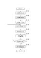
次に、本実施形態に係る光源装置である励起光照射装置70のプロジェクタ10への組込み方法を説明する。図9は、本発明の実施形態に係るプロジェクタ10の製造方法を説明するためのフローチャートである。図10は、本発明の実施形態に係る光源装置である励起光照射装置70の組み立て順を示す図である。
Next, a method of incorporating the excitation
ステップS101において、光源装置である励起光照射装置70を組み立てる工程を行う。詳細には、コリメータレンズ73をレンズ保持体79に取り付け、光源保持体80をレンズ保持体79に取り付け、図10(a)、図10(b)に示すように、光源保持体80とレンズ保持体79をそれぞれ嵌合方向(P1、P2)に沿って移動させて、光源保持体80の突出部80aとレンズ保持体79の受け座部79dとを嵌合させ、ネジ87により光源保持体80とレンズ保持体79とを固定して一体とする。
In step S101, a step of assembling the excitation
ステップS105において、励起光照射装置70の調整工程を行う。詳細には、図10(b)に示した状態で、レンズ保持体79に保持されたコリメータレンズ73の光軸調整を行うことで、励起光源71の光軸とコリメータレンズ73の光軸と合わせる調整を行い、それぞれの光軸を一致させた状態で、コリメータレンズ73を押え板89によりレンズ保持体79に固定させる。
In step S105, the adjustment process of the excitation
尚、上記実施形態では、ネジ87によりレンズ保持体79と光源保持体80とを固定したのちコリメータレンズ73の光軸と励起光源71の光軸とを合わせる調整を行ったが、この実施形態に限られるものではなく、例えば、コリメータレンズ73の光軸と励起光源71の光軸とを合わせる調整を行ったのち、ネジ87によりレンズ保持体79と光源保持体80とを固定してもよい。
In the above embodiment, the
ステップS110において、光源保持体80とレンズ保持体79とをネジ87により固定した励起光照射装置70を、プロジェクタ10の筐体に実装する工程を行う。詳細には、励起光照射装置70をプロジェクタ10の筐体内の所定位置に組み込んで筐体に固定する。
In step S <b> 110, a step of mounting the excitation
ステップS115において、プロジェクタ10の光学特性の調整工程を行う。詳細には、プロジェクタ10の光学特性の調整として、例えば、導光光学系140と光源側光学系170と投影側光学系220等の光学系ユニット160、表示素子51、励起光照射装置70等の光学特性に関する調整を行う。
In step S115, an optical characteristic adjustment process of the
ステップS120において、係止部材であるネジ320の取付け工程を行う。詳細には、図10(c)に示すように、ネジ320を、筐体の開口部16b側から光源保持体80の突出部80aの貫通孔80bに貫通するとともに、レンズ保持体79の受け座部79dの受け穴79eに挿入して固定する。
In step S120, a process of attaching the
ステップS125において、励起光照射装置70を組み込んだプロジェクタ10に対して全体的な動作に関する総合検査及び最終調整を行う。詳細には、例えば、プロジェクタ10による照度等が基準レベルを満たすか否かの動作チェックを行う。
In step S125, comprehensive inspection and final adjustment regarding the overall operation are performed on the
ステップS130において、総合検査の結果、規定された基準レベルを満たした合格品か否かを判別する。総合検査の結果、規定された基準レベルを満たす場合には、ステップS135の処理に進む。 In step S130, as a result of the comprehensive inspection, it is determined whether or not the product is a qualified product that satisfies a specified reference level. As a result of the comprehensive inspection, if the prescribed reference level is satisfied, the process proceeds to step S135.
ステップS135において、プロジェクタ10内の励起光照射装置70のネジ320に対して、取外し防止処理を施す。詳細には、図4、図5に示すように、筐体の底パネル蓋16aを取り外し、開口部16bに励起光照射装置70のネジ320の頭部320bを露出させ、図10(d)、図8に示すように、突出部80aの凹穴部80cに封止剤330として接着剤を充填し、頭部320bを凹穴部80cに埋設させる。所定時間後、封止剤330が硬化することで、ネジ320の取外しが困難となる。その後、開口部16bに底パネル蓋16aをネジ16c、16dにより固定する。
In step S135, a removal prevention process is performed on the
このように、励起光照射装置70は、図8に示すように、ネジ320が突出部80aの貫通孔80bに遊嵌するとともに受け座部79dの受け穴79eに固定しているので、光源保持体80とレンズ保持体79との離間が困難で、励起光源71を取り出すことが困難な構造となる。
In this way, as shown in FIG. 8, in the excitation
詳細には、例えば光源保持体80とレンズ保持体79とが離間する方向に外力が加わった場合であっても、突出部80aが受け座部79dに嵌合した状態で、その離間する方向と直交する方向に沿って、略棒形状のネジ320が、突出部80aの貫通孔80bに遊嵌するとともに受け座部79dの受け穴79eに固定しているので、光源保持体80とレンズ保持体79が離間することが困難である。
Specifically, for example, even when an external force is applied in a direction in which the light
また、図10(d)に示すように、励起光照射装置70において、光源保持体80の突出部80aとレンズ保持体79の受け座部79dとの間に、例えば光軸微調整用の隙間が形成されている構造を有する場合、ネジ87やそのネジ87の取付け穴の位置関係が、光軸を微調整可能なように構成されていることが好ましい。
Further, as shown in FIG. 10D, in the excitation
また、上述した光源保持体80とレンズ保持体79との間の隙間に、流動性の高い接着剤を塗布し、光源保持体80とレンズ保持体79とを固着させることで、光源保持体80とレンズ保持体79との間のがたつきを防止するとともに、光源保持体80とレンズ保持体79とを離間させて励起光源71を取り外すことを更に困難とすることができる。
Further, a light-fluid adhesive is applied to the gap between the
また、ステップS130の動作検査の結果、基準レベルを満たさない場合は、所定の配装処理が行われる。 Further, as a result of the operation check in step S130, when the reference level is not satisfied, a predetermined distribution process is performed.
次に本発明の実施形態の変形例に係る光源装置を説明する。図11は、本発明の実施形態の変形例に係る光源装置の要部の拡大断面図である。図7、図8に示した実施形態と同様な構成、効果については説明を省略し、相違点を説明する。 Next, a light source device according to a modification of the embodiment of the present invention will be described. FIG. 11 is an enlarged cross-sectional view of a main part of a light source device according to a modification of the embodiment of the present invention. The description of the same configurations and effects as those of the embodiment shown in FIGS. 7 and 8 will be omitted, and differences will be described.
図11に示すように、光源装置としての励起光照射装置70aでは、第1の保持体である光源保持体80は、突出部80aを有する。第2の保持体であるレンズ保持体79は、受け座部79dを有する。突出部80aは受け座部79dに対して、筐体の開口部16b側となるように構成されている。ネジ320は、突出部80aの貫通孔80bに固定され、受け座部79dの受け穴79eに遊嵌するように構成されている。詳細には、突出部80aの貫通孔80bには、雌ネジである螺合部が形成されており、この螺合部にネジ320の本体部320aの雄ネジが螺合するように構成されている。つまり、ネジ320は、貫通孔80bに貫通固定し、受け穴79eに遊嵌している。
As shown in FIG. 11, in the excitation
上記励起光照射装置70aを採用したプロジェクタ10では、上記ネジ320が突出部80aの貫通孔80bに固定され、受け座部79dの受け穴79eに遊嵌するように構成されているので、製造時に煩雑な工程を行うことなく、簡単な構造で、プロジェクタ筐体内の励起光照射装置70aの励起光源71を他の用途に用いるために取外すことを防止可能である。
In the
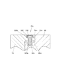
次に本発明の実施形態の他の変形例に係る光源装置を説明する。図12は、本発明の実施形態の他の変形例に係る光源装置の要部の拡大断面図である。図7、図8に示した実施形態と同様な構成、効果については説明を省略し、相違点を説明する。 Next, a light source device according to another modification of the embodiment of the present invention will be described. FIG. 12 is an enlarged cross-sectional view of a main part of a light source device according to another modification of the embodiment of the present invention. The description of the same configurations and effects as those of the embodiment shown in FIGS. 7 and 8 will be omitted, and differences will be described.
図12に示すように、光源装置としての励起光照射装置70bでは、第2の保持体であるレンズ保持体79は、突出部79mを有する。第1の保持体である光源保持体80は、受け座部80mを有する。突出部79mは受け座部80mに対して、筐体の開口部16b側となるように構成されている。ネジ320は、突出部79mの貫通孔79nに遊嵌し、受け座部80mの受け穴80nに固定するように構成されている。詳細には、受け座部80mの受け穴80nには、雌ネジである螺合部が形成されており、この螺合部にネジ320の本体部320aの雄ネジが螺合するように構成されている。
As shown in FIG. 12, in the excitation light irradiation device 70b as the light source device, the
上記励起光照射装置70bを採用したプロジェクタ10では、上記ネジ320が突出部79mの貫通孔79nに遊嵌し、受け座部80mの受け穴80nに固定するように構成されているので、製造時に煩雑な工程を行うことなく、簡単な構造で、プロジェクタ筐体内の励起光照射装置70bの励起光源71を他の用途に用いるために取外すことを防止可能である。また、封止剤330として高い流動性の接着剤を用いることで、レンズ保持体79と光源保持体80との間の隙間を封止することができ、更に、励起光源71の取外しを困難とすることができる。
In the
次に本発明の実施形態の他の変形例に係る光源装置を説明する。図13は、本発明の実施形態の他の変形例に係る光源装置の要部の拡大断面図である。図12に示した実施形態と同様な構成、効果については説明を省略し、相違点を説明する。 Next, a light source device according to another modification of the embodiment of the present invention will be described. FIG. 13: is an expanded sectional view of the principal part of the light source device which concerns on the other modification of embodiment of this invention. A description of the same configuration and effects as those of the embodiment shown in FIG. 12 will be omitted, and differences will be described.
図13に示すように、励起光照射装置70cでは、第2の保持体であるレンズ保持体79は、突出部79mを有する。第1の保持体である光源保持体80は、受け座部80mを有する。突出部79mは受け座部80mに対して、筐体の開口部16b側となるように構成されている。ネジ320は、突出部79mの貫通孔79nに貫通固定され、受け座部80mの受け穴80nに遊嵌するように構成されている。詳細には、突出部79mの貫通孔79nには、雌ネジである螺合部が形成されており、この螺合部にネジ320の本体部320aの雄ネジが螺合するように構成されている。
As shown in FIG. 13, in the excitation
上記励起光照射装置70cを採用したプロジェクタ10では、上記ネジ320が突出部79mの貫通孔79nに貫通固定され、受け座部80mの受け穴80nに遊嵌するように構成されているので、製造時に煩雑な工程を行うことなく、簡単な構造で、プロジェクタ筐体内の励起光照射装置70cの励起光源71を他の用途に用いるために取外すことを防止可能である。
In the
尚、図7に示した実施の形態は、突出部80a及び突出部80aに嵌合させる受け座部79dを、光源保持体80やレンズ保持体79の周囲四面に設けることとしているも、突出部80aや受け座部79dは、光源保持体80、レンズ保持体79の少なくとも底面側の一面とすることも可能であり、底面側の一面を含む二面又は三面とすることがあり、底面側の突出部80aの表面に凹穴部80cを設けるものである。
In the embodiment shown in FIG. 7, the
また、係止部材としてはネジ320に限るものではなく、凹穴部80cに収納される頭部320bと頭部320bよりも直径の小さな棒状の本体部320aとを有し、頭部320bを凹穴部80cに収容して、本体部320aの先端が、受け座部79dの受け穴79eに挿入されるものであれば足りる。
Further, the locking member is not limited to the
以上のように、本発明によれば、光源装置である励起光照射装置は、光源としての励起光源71を保持する第1の保持体である光源保持体80と、光源保持体80に保持された励起光源71から射出される光を集光するコリメータレンズ73を保持する第2の保持体であるレンズ保持体79と、を備え、レンズ保持体79と光源保持体80とを固定する固定部材であるネジ87により光源保持体80とレンズ保持体79とが一体とされる。また、励起光照射装置は、光源保持体80からレンズ保持体79側に又はレンズ保持体79から光源保持体80側に突出する突出部80aを有するとともにレンズ保持体79又は光源保持体80に突出部80aを受ける切欠き部を備える受け座部79dを有し、突出部80aに係止部材であるネジ320を挿入する貫通孔80bを有する。ネジ320は、棒状の本体部320aを有してその本体部320aを突出部80aに設けられた貫通孔80bを貫通させて受け座部79dに設けられた受け穴79eに先端を挿入し封止剤330によりその頭部320bが埋設されている。このため、製造時に煩雑な工程を行うことなく、簡単な構造で、プロジェクタ筐体内の光源装置の光源を他の用途に用いるために取り外すことを防止可能な、光源装置、プロジェクタ、及び光源装置の組込み方法を提供することができる。
As described above, according to the present invention, the excitation light irradiation device that is a light source device is held by the
また、本発明によれば、励起光照射装置において、係止部材であるネジ320は、第1の保持体である光源保持体80と第2の保持体であるレンズ保持体79のどちらか一方に遊嵌された状態で、封止剤330によりその頭部320bが埋設されている。つまり、ネジ320が、第1の保持体と第2の保持体のどちらか一方に遊嵌した状態であり、励起光源71とコリメータレンズ73の光軸ずれを防止することができ、且つ、簡単な構造で、プロジェクタ筐体内の光源装置の光源を他の用途に用いるために取り外すことを防止可能な、光源装置、プロジェクタ、及び光源装置の組込み方法を提供することができる。
According to the present invention, in the excitation light irradiation device, the
また、本発明によれば、ネジ320が挿入される貫通孔80bの貫通方向は、レンズ保持体79と光源保持体80とを固定する固定部材であるネジ87の挿入方向と異なるので、レンズ保持体79と光源保持体80を分離して、励起光照射装置内の励起光源71を取り外すことをより困難とすることができる。
In addition, according to the present invention, the penetration direction of the through
また、本発明によれば、突出部80aの表面には、係止部材であるネジ320の頭部320bを収納する凹穴部80cをさらに有し、ネジ320の頭部320bが、凹穴部80cに収納された状態で、封止剤330により埋設されている。このため、ネジ320の取り外しが更に困難となり、プロジェクタ筐体内の光源装置の光源を他の用途に用いるために取り外すことを防止可能な、光源装置、プロジェクタ、及び光源装置の組込み方法を提供することができる。
In addition, according to the present invention, the surface of the projecting
また、本発明によれば、励起光照射装置において、係止部材であるネジ320の本体部320aには雄ネジが形成され、貫通孔80bはネジ320の本体部320aよりも直径が大きく形成され、受け穴79eにはネジ320の本体部320aに形成された雄ネジと螺合する雌ネジが形成されている。すなわち、係止部材であるネジ320が確実に受け穴79eに固定され、封止剤330により封止されているので、ネジ320の取り外しが困難であり、励起光照射装置内の励起光源71を取り外すことが困難とする構造とすることができる。
Further, according to the present invention, in the excitation light irradiation device, the
さらに、本発明によれば、突出部80aは、光源保持体80又はレンズ保持体79の周囲に形成され、突出部80aの表面に形成される凹穴部80cは、その突出部80aが形成された光源保持体80又はレンズ保持体79の一側面の部分にのみ形成される。このため、凹穴部80cが複数の側面に形成された場合と比較して、製造時に、煩雑な工程を行うことなく、上記一側面の部分に形成された凹穴部80cに、ネジ320を配置することで、簡単に、励起光照射装置を製造することができる。
Further, according to the present invention, the
また、本発明によれば、例えば、突出部80aには少なくとも3つの凹穴部80cが形成され、凹穴部80cのうち少なくとも1つは他の凹穴部80cとは突出部80aの先端部までの距離が異なるように構成することで、更に、励起光照射装置内の励起光源71を取り外すことが困難とする構造とすることができる。詳細には、例えば、図5、図6に示した2つの突出部80aの中間部の先端側に、他の凹穴部80cとは突出部80aの先端部までの距離が異なる凹穴部80cを設けてもよい。そして、複数の凹穴部80cそれぞれに対応するように、上記受け座部79dに複数の受け穴79eを設け、それらに対応する複数のネジ320を設ける。こうすることで、励起光照射装置内の励起光源71の取り外しを更に困難にすることができる。
In addition, according to the present invention, for example, at least three recessed
さらに、本発明によれば、複数の光源装置である励起光照射装置と、複数の励起光照射装置の発する光を同一光軸とする導光光学系140と、表示素子51と、導光光学系140により同一光軸とされた光を表示素子51に導く光源側光学系170と、表示素子51により形成される光学像をスクリーンに投影する投影側光学系220と、冷却装置である冷却ファン261と、励起光照射装置や表示素子51及び冷却ファン261を制御するプロジェクタ制御手段である制御部38と、を備え、複数の励起光照射装置の内、少なくとも一つが上記励起光照射装置である。このため、簡単な構造で、全体検査に合格したプロジェクタ筐体内の光源装置の光源を他の用途に用いるために取り外すことを防止可能な、プロジェクタに組み込む光源装置、プロジェクタ、及び光源装置の組込み方法を提供することができる。
Furthermore, according to the present invention, the excitation light irradiation device that is a plurality of light source devices, the light guide
また、本発明によれば、励起光照射装置における突出部80aに設けられる凹穴部80cは、励起光照射装置の下面側であり、励起光照射装置はプロジェクタ底面に設けられる開口部16bの内側に配置されている。このため、製造時に、煩雑な工程を行うことなく、簡単に、励起光照射装置、及びそれを備えたプロジェクタを製造することができる。
Further, according to the present invention, the recessed
さらに、本発明によれば、上記構成の励起光照射装置を備えたプロジェクタ10における励起光照射装置の組込み方法であって、コリメータレンズ73の光軸と励起光源71の光軸とを合わせる調整を行った後、固定ネジであるネジ87によりレンズ保持体79と光源保持体80とを固定し、レンズ保持体79と光源保持体80とを固定した励起光照射装置をプロジェクタ10の筐体内に組み込んで、プロジェクタの光学特性の調整を行った後、係止部材であるネジ320を凹穴部80cに挿入し、プロジェクタ10の総合検査を行った後、凹穴部80cに封止剤330を充填するので、製造時に煩雑な工程を行うことなく、簡単な構造で、全体検査に合格したプロジェクタ筐体内の励起光照射装置の励起光源71を他の用途に用いるために取り外すことを防止可能な、プロジェクタ10に組み込む光源装置、プロジェクタ10、及び光源装置の組込み方法を提供することができる。
Furthermore, according to the present invention, there is provided a method for incorporating an excitation light irradiation device in the
また、比較例に係るプロジェクタとして、上記ネジ320を用いることなく、レンズ保持体79と光源保持体80との間の隙間に嫌気性接着剤を塗布して、レンズ保持体79と光源保持体80とを固着させることで、励起光源71の取外し防止させる構造を有するものでは、例えば予め複数の厚みのスペーサを準備しておき、レンズ保持体79と光源保持体80の隙間に対応したスペーサを配置した後、嫌気性接着剤を塗布して固着するという、煩雑な製造工程を行うことを要する。一方、本発明に係る光源装置の組込み方法では、そのような煩雑な工程を行うことなく、簡単な製造工程で、上記効果を有する光源装置及びこの光源装置を組込んだプロジェクタ10を作製することができる。
Further, as a projector according to the comparative example, an anaerobic adhesive is applied to the gap between the
本発明は、上記実施形態及び変形例に限定されるものではなく、発明の要旨を逸脱しない範囲で自由に変更、改良が可能である。本発明の実施形態に係るプロジェクタでは、ネジ320に封止剤330を塗布して、ネジ320を取外し困難に構成されていたが、この形態に限られるものではない。例えばネジ320の頭部320bの溝の形状を変形させることで、取外し困難に構成してもよい。また、ネジ320の代わりに、取外し困難な形状のリベットを用いてもよい。
The present invention is not limited to the above embodiments and modifications, and can be freely changed and improved without departing from the spirit of the invention. In the projector according to the embodiment of the present invention, the
また、例えば励起光源71とコリメータレンズ73との光軸調整のために、光源保持体80の突出部80aと、レンズ保持体79の受け座部79dとの間に、所定の隙間が形成された構造の場合、ネジ87の取付け位置を適宜調整可能に設けられることが好ましい。
Further, for example, a predetermined gap is formed between the protruding
また、上記各実施形態では、レンズ保持体79と光源保持体80のP1、P2方向と垂直な側面が、互いに接触しているような図で説明したが、光軸調整の機構によっては、隙間がある場合でもよい。
Further, in each of the above embodiments, the side surfaces perpendicular to the P1 and P2 directions of the
上記各実施形態では、突出部の表面に係止部材の頭部を収納する凹穴部を有する例で説明したが、凹穴部は必ずしも必要ではなく、なくてもよい。凹穴部があると、封止剤を充填しやすく、封止しやすいといった利点がある。 In each of the above-described embodiments, the example in which the concave portion that accommodates the head of the locking member is provided on the surface of the protruding portion has been described, but the concave portion is not necessarily required. When there is a recessed hole, there is an advantage that it is easy to fill the sealant and easy to seal.
以下に、本願出願の最初の特許請求の範囲に記載された発明を付記する。
[1] 光源を保持する第1の保持体と、前記第1の保持体に保持された前記光源から射出される光を集光するコリメータレンズを保持する第2の保持体と、を備え、前記第2の保持体と前記第1の保持体とを固定する固定部材により前記第1の保持体と前記第2の保持体が一体とされる光源装置であって、
前記第1の保持体から前記第2の保持体側に又は前記第2の保持体から前記第1の保持体側に突出する突出部を有するとともに前記第2の保持体又は前記第1の保持体に前記突出部を受ける切欠き部を備える受け座部を有し、前記突出部に係止部材を挿入する貫通孔を有し、
前記係止部材は、棒状の本体部を有して該本体部を前記突出部に設けられた前記貫通孔を貫通させて前記受け座部に設けられた受け穴に先端を挿入し封止剤によりその頭部が埋設されていることを特徴とする光源装置。
[2] 前記係止部材は、前記第1の保持体と前記第2の保持体のどちらか一方に遊嵌された状態で、封止剤によりその頭部が埋設されていることを特徴とする請求項1に記載の光源装置。
[3] 前記係止部材が挿入される前記貫通孔の貫通方向は、前記第2の保持体と前記第1の保持体とを固定する前記固定部材の固定方向と異なることを特徴とする請求項1又は請求項2に記載の光源装置。
[4] 前記突出部の表面は、前記係止部材の頭部を収納する凹穴部をさらに有し、
前記係止部材の頭部が、前記凹穴部に収納された状態で、封止剤により埋設されていることを特徴とする請求項1乃至請求項3の何れかに記載の光源装置。
[5] 前記係止部材の前記本体部には雄ネジが形成され、
前記貫通孔は、前記係止部材の本体部よりも直径が大きく、
前記受け穴には前記係止部材の前記本体部に形成された前記雄ネジと螺合する雌ネジが形成されていることを特徴とする請求項1乃至請求項4の何れかに記載の光源装置。
[6] 前記突出部は、前記第1の保持体又は前記第2の保持体の周囲に形成され、前記突出部の表面に形成される前記貫通孔は、該突出部が形成された前記第1又は第2の保持体の一側面の部分にのみ形成されることを特徴とする請求項1乃至請求項5の何れかに記載の光源装置。
[7] 前記突出部には少なくとも3つの前記貫通孔が形成され、前記貫通孔のうち少なくとも1つは他の貫通孔とは前記突出部の先端部までの距離が異なることを特徴とする請求項1乃至請求項6の何れかに記載した光源装置。
[8] 光源装置と、前記光源装置の発する光を同一光軸とする導光光学系と、表示素子と、前記導光光学系により前記同一光軸とされた光を前記表示素子に導く光源側光学系と、前記表示素子により形成される光学像をスクリーンに投影する投影側光学系と、冷却装置と、前記光源装置や前記表示素子及び前記冷却装置を制御するプロジェクタ制御手段と、を備え、
前記光源装置が前記請求項1乃至請求項7の何れかの光源装置であることを特徴とするプロジェクタ。
[9] 前記請求項1乃至請求項7の何れかの光源装置における前記突出部に設けられる前記貫通孔は、前記光源装置の下面側であり、該光源装置はプロジェクタ底面に設けられる開口部の内側に配置されていることを特徴とする請求項8に記載のプロジェクタ。
[10] 光源を保持する第1の保持体と、前記第1の保持体に保持された前記光源から射出される光を集光するコリメータレンズを保持する第2の保持体と、を備え、前記第2の保持体と前記第1の保持体とを固定する固定ネジにより前記第1の保持体と前記第2の保持体が一体とされ、前記第1の保持体から前記第2の保持体側に又は前記第2の保持体から前記第1の保持体側に突出する突出部を有するとともに前記第2の保持体又は前記第1の保持体に前記突出部を受ける切欠き部を備える受け座部を有し、前記突出部に係止部材を挿入する貫通孔を有し、前記係止部材は棒状の本体部を有して該本体部を前記突出部に設けられた貫通孔を貫通させて前記受け座部に設けられた受け穴に先端を挿入し封止剤によりその頭部が埋設されている光源装置を備えたプロジェクタにおける前記光源装置の組込み方法であって、
前記コリメータレンズの光軸と前記光源の光軸とを合わせる調整を行ったのち前記固定ネジにより前記第2の保持体と前記第1の保持体とを固定し、又は、前記固定ネジにより前記第2の保持体と前記第1の保持体とを固定したのち前記コリメータレンズの光軸と前記光源の光軸とを合わせる調整を行い、
前記第2の保持体と前記第1の保持体とを固定した光源装置をプロジェクタの筐体内に組み込んで、前記プロジェクタの光学特性の調整を行った後、前記係止部材を前記凹穴部に挿入し、
前記プロジェクタの総合検査を行った後、前記凹穴部に前記封止剤を充填することを特徴とするプロジェクタにおける光源装置の組込み方法。
The invention described in the first claim of the present application will be appended below.
[1] A first holding body that holds a light source, and a second holding body that holds a collimator lens that collects light emitted from the light source held by the first holding body, A light source device in which the first holding body and the second holding body are integrated by a fixing member that fixes the second holding body and the first holding body,
The second holding body or the first holding body has a protruding portion that protrudes from the first holding body to the second holding body or from the second holding body to the first holding body. It has a receiving seat with a notch for receiving the protrusion, and has a through hole for inserting a locking member into the protrusion,
The locking member has a rod-shaped main body portion, and the main body portion passes through the through hole provided in the projecting portion, and a tip is inserted into a receiving hole provided in the receiving seat portion. A light source device characterized in that its head is embedded.
[2] The locking member has a head embedded in a sealant in a state of loosely fitting in either the first holding body or the second holding body. The light source device according to claim 1.
[3] The penetration direction of the through hole into which the locking member is inserted is different from the fixing direction of the fixing member that fixes the second holding body and the first holding body. Item 3. A light source device according to item 1 or 2.
[4] The surface of the protruding portion further includes a recessed hole portion that houses the head of the locking member,
4. The light source device according to claim 1, wherein a head portion of the locking member is embedded with a sealant in a state of being accommodated in the recessed hole portion.
[5] A male screw is formed on the main body of the locking member,
The through hole has a larger diameter than the main body of the locking member,
5. The light source according to claim 1, wherein the receiving hole is formed with a female screw that is screwed with the male screw formed in the main body portion of the locking member. apparatus.
[6] The protruding portion is formed around the first holding body or the second holding body, and the through hole formed in the surface of the protruding portion is the first portion where the protruding portion is formed. The light source device according to any one of claims 1 to 5, wherein the light source device is formed only on one side portion of the first or second holding body.
[7] At least three of the through holes are formed in the protrusion, and at least one of the through holes is different in distance from the other through hole to the tip of the protrusion. The light source device according to any one of claims 1 to 6.
[8] A light source device, a light guide optical system having light emitted from the light source device as the same optical axis, a display element, and a light source for guiding the light having the same optical axis by the light guide optical system to the display element A side optical system, a projection side optical system that projects an optical image formed by the display element onto a screen, a cooling device, and a projector control unit that controls the light source device, the display element, and the cooling device. ,
The projector according to claim 1, wherein the light source device is the light source device according to claim 1.
[9] In the light source device according to any one of claims 1 to 7, the through hole provided in the projecting portion is on a lower surface side of the light source device, and the light source device is an opening provided on a bottom surface of the projector. The projector according to
[10] A first holding body that holds a light source, and a second holding body that holds a collimator lens that collects light emitted from the light source held by the first holding body, The first holding body and the second holding body are integrated with each other by a fixing screw that fixes the second holding body and the first holding body, and the second holding body is moved from the first holding body to the second holding body. A receiving seat that has a protruding portion that protrudes toward the first holding body from the second holding body and has a notch that receives the protruding portion from the second holding body or the first holding body. And has a through-hole into which the locking member is inserted into the protruding portion, and the locking member has a rod-shaped main body portion and allows the main body portion to pass through the through-hole provided in the protruding portion. The tip is inserted into the receiving hole provided in the receiving seat and the head is embedded with a sealing agent. A method of incorporating the light source device in a projector including the light source device comprising:
After adjusting the optical axis of the collimator lens and the optical axis of the light source, the second holding body and the first holding body are fixed by the fixing screw, or the first screw is fixed by the fixing screw. After fixing the holding body of 2 and the first holding body, adjustment is performed to match the optical axis of the collimator lens and the optical axis of the light source,
A light source device in which the second holding body and the first holding body are fixed is incorporated in a projector housing, and after adjusting the optical characteristics of the projector, the locking member is inserted into the recessed hole portion. Insert,
A method of assembling a light source device in a projector, wherein after the comprehensive inspection of the projector is performed, the concave portion is filled with the sealant.
10 プロジェクタ
11 上面パネル 12 正面パネル
13 背面パネル 14 右側パネル
15 左側パネル 16 底面パネル
16a 底パネル蓋 16b 開口部
16c、16d ネジ 17 排気孔
18 吸気孔 19 レンズカバー
20 各種端子 21 入出力コネクタ部
22 入出力インターフェース 23 画像変換部
24 表示エンコーダ 25 ビデオRAM
26 表示駆動部 31 画像圧縮伸長部
32 メモリカード 35 Ir受信部
36 Ir処理部 37 キー/インジケータ部
38 制御部 41 光源制御回路
43 冷却ファン駆動制御回路 45 レンズモータ
47 音声処理部 48 スピーカ
51 表示素子
60 光源ユニット 70、70a、70b、70c 励起光照射装置
71 励起光源 73 コリメータレンズ
74 レンズ取付枠 75 反射ミラー群
78 集光レンズ 79 レンズ保持体(第2の保持体)
79a 孔部 79b レンズ枠穴
79c 端面
79d 受け座部 79e 受け穴
79m 突出部 79n 貫通孔
80 光源保持体(第1の保持体) 80a 突出部
80b 貫通孔 80c 凹穴部
80m 受け座部 80n 受け穴
81 ヒートシンク
87 ネジ(固定部材) 89 押え板
90 フレキシブル基板 92 リード線端子部
100 蛍光発光装置 101 蛍光ホイール
110 ホイールモータ 111 集光レンズ群
120 赤色光源装置 121 赤色光源
125 集光レンズ群 130 ヒートシンク
140 導光光学系 141 第一ダイクロイックミラー
148 第二ダイクロイックミラー 160 光学系ユニット
161 照明側ブロック 165 画像生成ブロック
168 投影側ブロック 170 光源側光学系
173 集光レンズ 175 ライトトンネル
178 集光レンズ 181 光軸変換ミラー
183 集光レンズ 185 照射ミラー
190 ヒートシンク 195 集光レンズ
220 投影側光学系 225 固定レンズ群
235 可動レンズ群 241 制御回路基板
261 冷却ファン 300 青色光源装置
301 青色光源 305 集光レンズ群
310 ヒートシンク 320 ネジ(係止部材)
320a 本体部 320b 頭部
330 封止剤 500 隙間
10 Projector
11
13
15
16a
16c,
18
20
22 I /
24
26
32
36
38
43 Cooling fan
47
51 Display element
60
71
74
78
79c end face
80 Light source holder (first holder) 80a Projection
80b Through
81 heat sink
87 Screw (fixing member) 89 Presser plate
90
100 Fluorescent
110
120 Red
125
140 Light guide
148 Second
161
168 Projection side block 170 Light source side optical system
173
178
183
190
220 Projection-side
235
261
301 Blue
310
Claims (10)
前記第1の保持体から前記第2の保持体側に又は前記第2の保持体から前記第1の保持体側に突出する突出部を有するとともに前記第2の保持体又は前記第1の保持体に前記突出部を受ける切欠き部を備える受け座部を有し、前記突出部に係止部材を挿入する貫通孔を有し、
前記係止部材は、棒状の本体部を有して該本体部を前記突出部に設けられた前記貫通孔を貫通させて前記受け座部に設けられた受け穴に先端を挿入し封止剤によりその頭部が埋設されていることを特徴とする光源装置。 A first holding body that holds a light source; and a second holding body that holds a collimator lens that collects light emitted from the light source held by the first holding body. A light source device in which the first holding body and the second holding body are integrated by a fixing member that fixes the holding body and the first holding body,
The second holding body or the first holding body has a protruding portion that protrudes from the first holding body to the second holding body or from the second holding body to the first holding body. It has a receiving seat with a notch for receiving the protrusion, and has a through hole for inserting a locking member into the protrusion,
The locking member has a rod-shaped main body portion, and the main body portion passes through the through hole provided in the projecting portion, and a tip is inserted into a receiving hole provided in the receiving seat portion. A light source device characterized in that its head is embedded.
前記係止部材の頭部が、前記凹穴部に収納された状態で、封止剤により埋設されていることを特徴とする請求項1乃至請求項3の何れかに記載の光源装置。 The surface of the protruding portion further includes a recessed hole portion that houses the head portion of the locking member,
4. The light source device according to claim 1, wherein a head portion of the locking member is embedded with a sealant in a state of being accommodated in the recessed hole portion.
前記貫通孔は、前記係止部材の本体部よりも直径が大きく、
前記受け穴には前記係止部材の前記本体部に形成された前記雄ネジと螺合する雌ネジが形成されていることを特徴とする請求項1乃至請求項4の何れかに記載の光源装置。 A male screw is formed on the main body of the locking member,
The through hole has a larger diameter than the main body of the locking member,
5. The light source according to claim 1, wherein the receiving hole is formed with a female screw that is screwed with the male screw formed in the main body portion of the locking member. apparatus.
前記光源装置が前記請求項1乃至請求項7の何れかの光源装置であることを特徴とするプロジェクタ。 A light source device, a light guide optical system having light emitted from the light source device as the same optical axis, a display element, and a light source side optical system for guiding light having the same optical axis by the light guide optical system to the display element A projection-side optical system that projects an optical image formed by the display element onto a screen, a cooling device, and a projector control unit that controls the light source device, the display element, and the cooling device,
The projector according to claim 1, wherein the light source device is the light source device according to claim 1.
前記コリメータレンズの光軸と前記光源の光軸とを合わせる調整を行ったのち前記固定ネジにより前記第2の保持体と前記第1の保持体とを固定し、又は、前記固定ネジにより前記第2の保持体と前記第1の保持体とを固定したのち前記コリメータレンズの光軸と前記光源の光軸とを合わせる調整を行い、
前記第2の保持体と前記第1の保持体とを固定した光源装置をプロジェクタの筐体内に組み込んで、前記プロジェクタの光学特性の調整を行った後、前記係止部材を前記凹穴部に挿入し、
前記プロジェクタの総合検査を行った後、前記凹穴部に前記封止剤を充填することを特徴とするプロジェクタにおける光源装置の組込み方法。
A first holding body that holds a light source; and a second holding body that holds a collimator lens that collects light emitted from the light source held by the first holding body. The first holding body and the second holding body are integrated with each other by a fixing screw for fixing the holding body and the first holding body, or from the first holding body to the second holding body side or A receiving seat having a protruding portion protruding from the second holding body toward the first holding body and having a notch for receiving the protruding portion in the second holding body or the first holding body; And the protrusion has a through-hole into which a locking member is inserted, and the locking member has a rod-shaped main body, and the main body is passed through the through-hole provided in the protrusion. A light source device in which the tip is inserted into a receiving hole provided in the seat and the head is embedded by a sealant. A built method of the light source device of the projector equipped with,
After adjusting the optical axis of the collimator lens and the optical axis of the light source, the second holding body and the first holding body are fixed by the fixing screw, or the first screw is fixed by the fixing screw. After fixing the holding body of 2 and the first holding body, adjustment is performed to match the optical axis of the collimator lens and the optical axis of the light source,
A light source device in which the second holding body and the first holding body are fixed is incorporated in a projector housing, and after adjusting the optical characteristics of the projector, the locking member is inserted into the recessed hole portion. Insert,
A method of assembling a light source device in a projector, wherein after the comprehensive inspection of the projector is performed, the concave portion is filled with the sealant.
Priority Applications (5)
| Application Number | Priority Date | Filing Date | Title |
|---|---|---|---|
| JP2011072140A JP5783405B2 (en) | 2011-03-29 | 2011-03-29 | Light source device, projector, and method for incorporating light source device |
| US13/432,541 US8801198B2 (en) | 2011-03-29 | 2012-03-28 | Light source device, projector, and method of assembling light source device |
| TW101110686A TWI448805B (en) | 2011-03-29 | 2012-03-28 | Light source device, projector, and method of assembling light source device |
| CN201210149364.7A CN102736385B (en) | 2011-03-29 | 2012-03-29 | Light source device, projector, and method of assembling light source device |
| HK13104504.6A HK1177264A1 (en) | 2011-03-29 | 2013-04-14 | Light source device, projector, and method of assembling light source device |
Applications Claiming Priority (1)
| Application Number | Priority Date | Filing Date | Title |
|---|---|---|---|
| JP2011072140A JP5783405B2 (en) | 2011-03-29 | 2011-03-29 | Light source device, projector, and method for incorporating light source device |
Publications (3)
| Publication Number | Publication Date |
|---|---|
| JP2012208207A true JP2012208207A (en) | 2012-10-25 |
| JP2012208207A5 JP2012208207A5 (en) | 2014-05-08 |
| JP5783405B2 JP5783405B2 (en) | 2015-09-24 |
Family
ID=46926847
Family Applications (1)
| Application Number | Title | Priority Date | Filing Date |
|---|---|---|---|
| JP2011072140A Active JP5783405B2 (en) | 2011-03-29 | 2011-03-29 | Light source device, projector, and method for incorporating light source device |
Country Status (5)
| Country | Link |
|---|---|
| US (1) | US8801198B2 (en) |
| JP (1) | JP5783405B2 (en) |
| CN (1) | CN102736385B (en) |
| HK (1) | HK1177264A1 (en) |
| TW (1) | TWI448805B (en) |
Cited By (2)
| Publication number | Priority date | Publication date | Assignee | Title |
|---|---|---|---|---|
| JP2016051802A (en) * | 2014-08-29 | 2016-04-11 | 日亜化学工業株式会社 | Light source device and projector including light source device |
| JP2017091737A (en) * | 2015-11-06 | 2017-05-25 | シャープ株式会社 | Light source device and lighting device |
Families Citing this family (17)
| Publication number | Priority date | Publication date | Assignee | Title |
|---|---|---|---|---|
| JP6070975B2 (en) * | 2011-11-02 | 2017-02-01 | カシオ計算機株式会社 | Optical device, method of assembling optical device, and projector provided with this optical device |
| JP5692654B2 (en) * | 2011-11-04 | 2015-04-01 | 株式会社リコー | Image projection device |
| TWI484284B (en) * | 2012-05-21 | 2015-05-11 | 台達電子工業股份有限公司 | Optical assembly and method for using the same |
| JP2014067568A (en) * | 2012-09-26 | 2014-04-17 | Sony Corp | Light source device, and projection device |
| TWI507794B (en) | 2013-10-25 | 2015-11-11 | Radiant Opto Electronics Corp | Backlight module and liquid crystal display |
| TWI575288B (en) * | 2013-10-25 | 2017-03-21 | 瑞儀光電股份有限公司 | Backlight module and liquid crystal display |
| CN104765230A (en) * | 2014-01-02 | 2015-07-08 | 光宝科技股份有限公司 | Micro projection fixing module |
| CN104793451B (en) * | 2014-01-20 | 2016-07-13 | 光宝科技股份有限公司 | Micro projection stuck-module |
| JP6442935B2 (en) * | 2014-03-20 | 2018-12-26 | セイコーエプソン株式会社 | projector |
| CN105573034B (en) * | 2015-06-18 | 2017-05-24 | 海信集团有限公司 | Laser light source and laser projection display device |
| CN106444241A (en) | 2015-08-04 | 2017-02-22 | 海信集团有限公司 | Laser light source and laser projection display device |
| CN108885388B (en) * | 2016-04-04 | 2021-10-19 | 索尼公司 | Light source device and image display device |
| US11099466B2 (en) | 2017-01-09 | 2021-08-24 | Goertek, Inc | Projection module and electronics apparatus |
| WO2018133025A1 (en) | 2017-01-20 | 2018-07-26 | 歌尔股份有限公司 | Portable earphone device |
| CN112433429B (en) * | 2020-08-18 | 2022-05-17 | 深圳市安华光电技术有限公司 | DLP projector, optical machine and LED light source device thereof |
| CN112433428B (en) * | 2020-08-18 | 2022-01-04 | 深圳市安华光电技术有限公司 | DLP projector, optical machine and LED light source device calibration method |
| JP2022146685A (en) * | 2021-03-22 | 2022-10-05 | セイコーエプソン株式会社 | Light source device and projector |
Citations (6)
| Publication number | Priority date | Publication date | Assignee | Title |
|---|---|---|---|---|
| JPH0714685U (en) * | 1993-07-29 | 1995-03-10 | ミツミ電機株式会社 | Fixed structure of parts |
| JPH10284803A (en) * | 1997-04-07 | 1998-10-23 | Ricoh Co Ltd | Light source device |
| JP2007019476A (en) * | 2005-06-09 | 2007-01-25 | Seiko Epson Corp | Laser light source device, display device, scanning display device, and projector |
| JP2007150028A (en) * | 2005-11-29 | 2007-06-14 | Sony Corp | Optical device adjustment method |
| JP2007311524A (en) * | 2006-05-18 | 2007-11-29 | Pentax Corp | Heat radiator of laser scanning apparatus |
| JP2008252141A (en) * | 2008-07-16 | 2008-10-16 | Matsushita Electric Works Ltd | Led-lighting device |
Family Cites Families (23)
| Publication number | Priority date | Publication date | Assignee | Title |
|---|---|---|---|---|
| JP3163619B2 (en) | 1990-05-15 | 2001-05-08 | 松下電器産業株式会社 | Projection lens device |
| US5617259A (en) * | 1994-03-07 | 1997-04-01 | Sony Corporation | Projection TV set apparatus |
| US5812215A (en) * | 1994-06-13 | 1998-09-22 | Mitsubishi Denki Kabushiki Kaisha | Projector display unit |
| JP3606649B2 (en) * | 1995-10-13 | 2005-01-05 | ソニー株式会社 | Projector device |
| US6115082A (en) * | 1996-03-08 | 2000-09-05 | U.S. Precision Lens Inc. | Coupler systems for projection televisions |
| US6239917B1 (en) * | 1998-10-23 | 2001-05-29 | Duke University | Thermalization using optical components in a lens system |
| JP2000241746A (en) * | 1999-02-24 | 2000-09-08 | Konica Corp | Optical deflector, method for controlling stop of optical deflector and image forming device |
| JP2001267670A (en) | 2000-03-16 | 2001-09-28 | Sony Corp | Laser device |
| JP3888045B2 (en) * | 2000-07-24 | 2007-02-28 | セイコーエプソン株式会社 | Projection display |
| US6441976B1 (en) * | 2001-05-15 | 2002-08-27 | Corning Precision Lens, Inc. | Lens system having compliant optic mounting structure |
| JP3928545B2 (en) * | 2002-11-08 | 2007-06-13 | ブラザー工業株式会社 | Optical member holding means, and optical scanning device and image forming apparatus including the same |
| US6922295B2 (en) * | 2003-09-19 | 2005-07-26 | 3M Innovative Properties Company | Lens assembly with integrated focus mount and CRT coupler |
| JP3748076B2 (en) * | 2003-10-22 | 2006-02-22 | 船井電機株式会社 | LCD televisions, panel display televisions |
| ITRM20040633A1 (en) * | 2004-12-23 | 2005-03-23 | St Microelectronics Srl | MULTI-SOURCE OPTICAL TRANSMITTER AND PHOTON DISPLAY DEVICE. |
| JP4274129B2 (en) * | 2005-01-31 | 2009-06-03 | セイコーエプソン株式会社 | projector |
| JP2008090945A (en) * | 2006-10-03 | 2008-04-17 | Funai Electric Co Ltd | Optical pickup |
| WO2008114502A1 (en) * | 2007-03-19 | 2008-09-25 | Panasonic Corporation | Laser illuminating device and image display device |
| TWI390335B (en) | 2009-03-25 | 2013-03-21 | Pleader Yamaichi Co Ltd | The lens trimming mechanism of the probe test device |
| US8393758B2 (en) * | 2009-04-16 | 2013-03-12 | Alps Electric Co., Ltd. | Laser light source device |
| JP4711154B2 (en) | 2009-06-30 | 2011-06-29 | カシオ計算機株式会社 | Light source device and projector |
| TWI405026B (en) * | 2009-07-29 | 2013-08-11 | Qisda Corp | Projector and lens thereof |
| CN201651903U (en) | 2010-03-29 | 2010-11-24 | 惠州多尔数码科技有限公司 | Water-resistant LED lamp |
| EP2424249A3 (en) * | 2010-08-31 | 2013-01-23 | Panasonic Corporation | Image display device and information processing device including the same |
-
2011
- 2011-03-29 JP JP2011072140A patent/JP5783405B2/en active Active
-
2012
- 2012-03-28 TW TW101110686A patent/TWI448805B/en active
- 2012-03-28 US US13/432,541 patent/US8801198B2/en active Active
- 2012-03-29 CN CN201210149364.7A patent/CN102736385B/en active Active
-
2013
- 2013-04-14 HK HK13104504.6A patent/HK1177264A1/en unknown
Patent Citations (6)
| Publication number | Priority date | Publication date | Assignee | Title |
|---|---|---|---|---|
| JPH0714685U (en) * | 1993-07-29 | 1995-03-10 | ミツミ電機株式会社 | Fixed structure of parts |
| JPH10284803A (en) * | 1997-04-07 | 1998-10-23 | Ricoh Co Ltd | Light source device |
| JP2007019476A (en) * | 2005-06-09 | 2007-01-25 | Seiko Epson Corp | Laser light source device, display device, scanning display device, and projector |
| JP2007150028A (en) * | 2005-11-29 | 2007-06-14 | Sony Corp | Optical device adjustment method |
| JP2007311524A (en) * | 2006-05-18 | 2007-11-29 | Pentax Corp | Heat radiator of laser scanning apparatus |
| JP2008252141A (en) * | 2008-07-16 | 2008-10-16 | Matsushita Electric Works Ltd | Led-lighting device |
Cited By (2)
| Publication number | Priority date | Publication date | Assignee | Title |
|---|---|---|---|---|
| JP2016051802A (en) * | 2014-08-29 | 2016-04-11 | 日亜化学工業株式会社 | Light source device and projector including light source device |
| JP2017091737A (en) * | 2015-11-06 | 2017-05-25 | シャープ株式会社 | Light source device and lighting device |
Also Published As
| Publication number | Publication date |
|---|---|
| TW201250369A (en) | 2012-12-16 |
| CN102736385B (en) | 2014-11-12 |
| US20120249981A1 (en) | 2012-10-04 |
| TWI448805B (en) | 2014-08-11 |
| CN102736385A (en) | 2012-10-17 |
| US8801198B2 (en) | 2014-08-12 |
| JP5783405B2 (en) | 2015-09-24 |
| HK1177264A1 (en) | 2013-08-16 |
Similar Documents
| Publication | Publication Date | Title |
|---|---|---|
| JP5783405B2 (en) | Light source device, projector, and method for incorporating light source device | |
| JP5316911B2 (en) | Light source device and projector | |
| US9477145B2 (en) | Light source device having laser light emitting elements adhesively fixed to a light source element holder, projector, and light source device fabrication method | |
| US9061378B2 (en) | Lens array, light source device, projector and light source device fabrication method | |
| JP5505719B2 (en) | Light source device and projector | |
| US20100245777A1 (en) | Light source unit utilizing laser for light source and projector | |
| JP5472721B2 (en) | Light source device and projector | |
| JP6070975B2 (en) | Optical device, method of assembling optical device, and projector provided with this optical device | |
| JP2014123014A (en) | Light source device, projector | |
| JP5783409B2 (en) | Light source device, projector, and method for incorporating light source device | |
| JP2013051126A (en) | Light source device, projector, and method for manufacturing of light source device | |
| JP2011113071A (en) | Rotation detecting device, light source unit, and projector | |
| JP2013196946A (en) | Light source device, projector, and manufacturing method of light source device | |
| JP6112333B2 (en) | Light source device and projector | |
| JP2013062172A (en) | Light source device, projector, and manufacturing method for light source device | |
| JP5880924B2 (en) | LIGHT SOURCE DEVICE, PROJECTOR, AND LIGHT SOURCE DEVICE MANUFACTURING METHOD | |
| JP5716959B2 (en) | Light source device and projector | |
| JP5835606B2 (en) | LIGHT SOURCE DEVICE, PROJECTOR, AND LIGHT SOURCE DEVICE MANUFACTURING METHOD | |
| US10247405B2 (en) | Light source unit, projector, and method of assembling a light source unit | |
| JP2013057788A (en) | Light source device, projector and manufacturing method of light source device | |
| JP5994885B2 (en) | Light source device and projector | |
| JP2015222726A (en) | Retainer and light source device | |
| JP2017146606A (en) | Light source device and projector |
Legal Events
| Date | Code | Title | Description |
|---|---|---|---|
| A521 | Written amendment |
Free format text: JAPANESE INTERMEDIATE CODE: A523 Effective date: 20140320 |
|
| A621 | Written request for application examination |
Free format text: JAPANESE INTERMEDIATE CODE: A621 Effective date: 20140320 |
|
| A977 | Report on retrieval |
Free format text: JAPANESE INTERMEDIATE CODE: A971007 Effective date: 20141218 |
|
| A131 | Notification of reasons for refusal |
Free format text: JAPANESE INTERMEDIATE CODE: A131 Effective date: 20150122 |
|
| A521 | Written amendment |
Free format text: JAPANESE INTERMEDIATE CODE: A523 Effective date: 20150217 |
|
| A131 | Notification of reasons for refusal |
Free format text: JAPANESE INTERMEDIATE CODE: A131 Effective date: 20150402 |
|
| A521 | Written amendment |
Free format text: JAPANESE INTERMEDIATE CODE: A523 Effective date: 20150529 |
|
| TRDD | Decision of grant or rejection written | ||
| A01 | Written decision to grant a patent or to grant a registration (utility model) |
Free format text: JAPANESE INTERMEDIATE CODE: A01 Effective date: 20150625 |
|
| A61 | First payment of annual fees (during grant procedure) |
Free format text: JAPANESE INTERMEDIATE CODE: A61 Effective date: 20150708 |
|
| R150 | Certificate of patent or registration of utility model |
Ref document number: 5783405 Country of ref document: JP Free format text: JAPANESE INTERMEDIATE CODE: R150 |