JP2012207699A - Ball bearing - Google Patents
Ball bearing Download PDFInfo
- Publication number
- JP2012207699A JP2012207699A JP2011072581A JP2011072581A JP2012207699A JP 2012207699 A JP2012207699 A JP 2012207699A JP 2011072581 A JP2011072581 A JP 2011072581A JP 2011072581 A JP2011072581 A JP 2011072581A JP 2012207699 A JP2012207699 A JP 2012207699A
- Authority
- JP
- Japan
- Prior art keywords
- cage
- ball
- ball bearing
- pockets
- raceway surface
- Prior art date
- Legal status (The legal status is an assumption and is not a legal conclusion. Google has not performed a legal analysis and makes no representation as to the accuracy of the status listed.)
- Granted
Links
Images

Classifications
-
- F—MECHANICAL ENGINEERING; LIGHTING; HEATING; WEAPONS; BLASTING
- F16—ENGINEERING ELEMENTS AND UNITS; GENERAL MEASURES FOR PRODUCING AND MAINTAINING EFFECTIVE FUNCTIONING OF MACHINES OR INSTALLATIONS; THERMAL INSULATION IN GENERAL
- F16C—SHAFTS; FLEXIBLE SHAFTS; ELEMENTS OR CRANKSHAFT MECHANISMS; ROTARY BODIES OTHER THAN GEARING ELEMENTS; BEARINGS
- F16C2380/00—Electrical apparatus
- F16C2380/26—Dynamo-electric machines or combinations therewith, e.g. electro-motors and generators
Landscapes
- Rolling Contact Bearings (AREA)
Abstract
Description
本発明は、例えば自動車トランスミッションやハイブリッド自動車または燃料電池自動車のモータ支持或いはモータに直結したギア支持に用いられるのに好適な転がり軸受である玉軸受に関し、更に詳しくは合成樹脂(プラスチック)製の保持器を備えた玉軸受に関する。 The present invention relates to a ball bearing which is a rolling bearing suitable for use in, for example, a motor support of a vehicle transmission, a hybrid vehicle, or a fuel cell vehicle or a gear support directly connected to the motor, and more particularly, a holding made of a synthetic resin (plastic). The present invention relates to a ball bearing provided with a vessel.
一般に、自動車のトランスミッションなどのように、油潤滑下で用いられる深溝玉軸受は、転動体である玉、内輪、外輪の材料として、軸受鋼であればSUJ2が、肌焼鋼であればSCR420やSCM420相当の鋼材等が用いられる。また、玉を転動自在に保持するための保持器には、SPCCからなる鉄製の波形プレス保持器又はプラスチック製の冠型保持器が使用される。 In general, deep groove ball bearings used under oil lubrication, such as automobile transmissions, are SUJ2 for bearing steel and SCR420 for case-hardened steel as materials for balls, inner rings and outer rings as rolling elements. A steel material or the like equivalent to SCM420 is used. In addition, an iron corrugated press holder made of SPCC or a plastic crown holder is used as a holder for holding the balls so as to roll freely.
近年、環境問題の高まりから、自動車のトランスミッションを構成する軸受部品においても、極めて低トルク化のニーズが高まっている。更に、玉軸受の[(内輪内径寸法(mm)+外輪外径寸法(mm))÷2]×回転速度(min−1)で示されるdmn値が65万以上という高速回転においても低トルクであることが求められている。 In recent years, due to increasing environmental problems, there is an increasing need for extremely low torque in bearing parts constituting automobile transmissions. Further, the ball bearing [(inner ring inner diameter dimension (mm) + outer ring outer diameter dimension (mm)) / 2] × rotational speed (min −1 ) has a dmn value of 650,000 or more and a low torque. There is a need to be.
玉軸受の摩擦損失トルクの原因として、[1]内外輪と玉との間の転がり摩擦、[2]内外輪と玉との間のすべり摩擦、[3]玉と保持器とのすべり摩擦、[4]
潤滑油の撹拌抵抗等があるが、玉軸受の低トルク化を達成する手段としては、負荷条件の軽減、軸受のサイズダウンが一般的である。
The causes of friction loss torque of ball bearings are [1] rolling friction between inner and outer rings and balls, [2] sliding friction between inner and outer rings and balls, [3] sliding friction between balls and cages, [4]
Although there is a stirring resistance of the lubricating oil, as means for achieving a reduction in torque of the ball bearing, reduction of load conditions and size reduction of the bearing are generally used.
しかしながら、このような手段においては、軸受寿命や剛性低下あるいは軸受取付周辺構造が制約される等の問題がある。 However, in such a means, there are problems such as a decrease in bearing life and rigidity, or a restriction on a bearing mounting peripheral structure.
また、上記[3]の観点では、近年では、トランスミッション用の玉軸受に、軽量かつ自己潤滑性に優れるプラスチック製の保持器が使用されることも増えている。 In addition, from the viewpoint of the above [3], in recent years, plastic cages that are lightweight and have excellent self-lubricating properties are increasingly used for transmission ball bearings.
また、上記[4]の観点では、軸受への供給油量の低減又は潤滑油の低粘度化などが考えられるが、これらの手段では、軸受、ユニットの性能面で制約を受けたり、当該ユニットの動作条件(
例えば、エンジンあるいはその他の回転部材の回転数) にも影響を受けるため、上記手法においてはコントロールし難いという問題がある。
Further, from the viewpoint of the above [4], it is conceivable to reduce the amount of oil supplied to the bearing or to lower the viscosity of the lubricating oil. However, with these means, there are restrictions on the performance of the bearing and unit, Operating conditions (
For example, there is a problem that it is difficult to control in the above method because it is also affected by the number of rotations of the engine or other rotating members.
従来の玉軸受用の保持器及び軸受として、図3、図4及び図5に示す冠型の構成のもの及びこの保持器を備える転がり軸受がある(例えば、特許文献1
参照)。図3は保持器の斜視図であり、図4は図3の保持器の部分展開図、図5は転がり軸受の断面図である。
As conventional cages and bearings for ball bearings, there are crown-shaped configurations shown in FIGS. 3, 4, and 5 and rolling bearings including the cage (for example, Patent Document 1).
reference). 3 is a perspective view of the cage, FIG. 4 is a partially developed view of the cage of FIG. 3, and FIG. 5 is a cross-sectional view of the rolling bearing.
保持器31はプラスチック製であり、いわゆる冠型に成形され、環状の保持器本体32は、軸方向の一方の面に、軸方向に向いて開口して玉を転動自在にかつ脱落不能に保持する複数のポケット35を円周方向に並んで有する。ポケット35は等間隔とされている。
The
これらポケット35の開口端部は、ポケット開口の保持器本体周方向の両側に位置する一対の爪片33a,33bにより形成され、ポケット35の内面は球面状とされている。ポケット3
5 の両側の爪片33a,33bは、互いに先端が近づく形状とされ、爪片33a,33b間の入口径は玉径よりも小さくされている。
The opening end portions of these
The
軸受の組み付けは、この爪片33a,33bの先端を玉36でわずかに押し広げるスナップオン方式によって行われる。つまり、上記保持器31に形成された爪片33a,33bはある程度自由に変形することが必要であり、剛性が高すぎると、組み付け性が低下したり、組み付け時に保持器31が破損したり、永久変形により玉挿入口である開口部が大きくなって回転中に保持器31が外れ易くなる恐れがある。
The assembly of the bearing is performed by a snap-on method in which the tips of the
したがって、一般的なプラスチック製の保持器31は、隣接する各ポケット35間における爪片33a,33bの間に凹部34があり、上記爪片33a,33bの弾性変形を可能にしている。また、保持器31には、肉盗み部19が設けられている。
Therefore, the general
しかしながら、これらの爪片33a,33bは、保持器本体32から湾曲しながら異なる方向に突出するという複雑な形状をしているため、軸受の回転時に不要に潤滑油を撹拌するという問題がある。
However, these
したがって、トルク低減のために、玉径を小さくしたり、玉数を減らすと、保持器31の正面側(ポケット側)に設けられた爪片33a,33bによる潤滑油の撹拌抵抗による影響が無視できない。特に軸受のPCD(ピッチ円直径)が大きい場合は、爪片33a,33bによる潤滑油の撹拌抵抗の影響が大きい。
Therefore, if the ball diameter is reduced or the number of balls is reduced in order to reduce torque, the influence of the stirring resistance of the lubricating oil by the
本発明の目的は、下記の構成により達成される。
玉軸受であって、
内輪軌道面を有する内輪と、
外輪軌道面を有する外輪と、
前記内輪軌道面と前記外輪軌道面との間に相対回転自在に配された複数の転動体である玉と、
前記転動体を転動自在に保持する合成樹脂製の保持器とを備え、
前記保持器を形成する合成樹脂が、引張り弾性率5GPa以上30GPa以下のグラスファイバー(GF)あるいはカーボンファイバー(CF)で強化された樹脂であり
前記保持器は環状の保持器本体に、玉を転動自在に保持する複数のポケットを円周方向に並んで有し、前記ポケットが前記保持器本体の軸方向一端側に開口し開口端部に玉保持用の一対の爪片を有するものであり、
隣接する前記ポケット間に、前記軸方向一端側に向けて突出する凸部が円周方向に沿って前記爪片と略同一の高さに設けられており、
前記ポケットの軸方向の肉厚最薄部における軸方向の幅が前記玉の直径(Da)の20%以上であり、
前記保持器においては実質的に肉盗みを有さないことを特徴とする玉軸受とするものである。
The object of the present invention is achieved by the following constitution.
A ball bearing,
An inner ring having an inner ring raceway surface;
An outer ring having an outer ring raceway surface;
Balls that are a plurality of rolling elements arranged in a relatively rotatable manner between the inner ring raceway surface and the outer ring raceway surface;
A cage made of a synthetic resin that holds the rolling element in a freely rollable manner,
The synthetic resin forming the cage is a resin reinforced with glass fiber (GF) or carbon fiber (CF) having a tensile modulus of elasticity of 5 GPa or more and 30 GPa or less, and the cage rolls balls onto the annular cage body. It has a plurality of pockets to be held movably arranged side by side in the circumferential direction, and the pockets open to one end side in the axial direction of the retainer body, and have a pair of claw pieces for holding balls at the open ends. ,
Between the adjacent pockets, a convex portion protruding toward the one end side in the axial direction is provided at substantially the same height as the claw piece along the circumferential direction,
The axial width in the axially thinnest portion of the pocket in the axial direction is 20% or more of the diameter (Da) of the ball,
The cage is a ball bearing characterized by having substantially no meat theft.
本発明の玉軸受は、特にdmn65万以上で使用される場合のある転がり軸受、あるいは特に、dmn65万以上の領域において、高速回転時のスキッディング防止、発熱防止、焼き付き防止、保持器破損の防止に効果があるだけではなく、潤滑油の攪拌抵抗を低減させることによりトルク低減効果も有する。 The ball bearing of the present invention is a rolling bearing that may be used in particular with a dmn of 650,000 or more, or in particular in a region of dmn of 650,000 or more, preventing skidding, heat generation, seizure prevention, and cage damage prevention during high-speed rotation. In addition to being effective, it also has a torque reduction effect by reducing the stirring resistance of the lubricating oil.
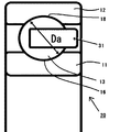
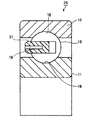
図1、2を用いて本発明の実施形態を詳細に説明する。図1は本発明の玉軸受を説明する図であり、図2は本発明の玉軸受を説明する図である。 An embodiment of the present invention will be described in detail with reference to FIGS. FIG. 1 is a diagram illustrating a ball bearing according to the present invention, and FIG. 2 is a diagram illustrating a ball bearing according to the present invention.
本発明の玉軸受20は、内輪軌道面16を有する内輪11と、外輪軌道面18を有する外輪12と、内輪軌道面16と外輪軌道面18との間に相対回転自在に配された複数の転動体である玉13と、合成樹脂製(プラスチック製)の保持器31とを備えている。
The ball bearing 20 of the present invention includes an
ここで、合成樹脂製の保持器31を形成する合成樹脂は、引っ張り弾性率5GPa以上30GPa以下のグラスファイバー(GF)、あるいは引張り弾性率5GPa以上30G Pa以下のカーボンファイバー(CF)を混合することにより強化された樹脂である。そのため、玉軸受20が、内輪回転もしくは外輪回転で高速回転しても、遠心力による変形等が少なく当初の寸法精度を維持することが可能であり、玉を良好に保持することができる。
Here, the synthetic resin forming the
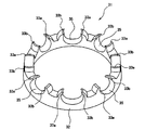
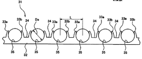
さらに、保持器31は環状の保持器本体32に玉13を転動自在に保持する複数のポケット35を円周方向に並んで有しており、ポケット35が保持器本体35の軸方向一端側に開口し開口端部に玉13を保持するための爪片33a、33bを有している。このポケット35及び爪片33a、33bにより玉13を保持している。この保持器31の形式はいわゆる冠型保持器である。
Further, the
さらに、複数のポケット35の間には、軸方向一端側に向けて突出する凸部17が円周方向に沿って設けられており、この凸部17の高さは爪片33a、33bと略同一となっている。すなわち、保持器31は、ポケット35、爪片33a、33bと凸部17との間のへこみ部を除き、円周方向断面において凹凸の少ない形状となっている。このため、玉軸受20が高速回転し、保持器31も高速で回転するような場合でも、必要量を超える潤滑油の巻き込みを押さえ、あるいはまた潤滑油の攪拌抵抗を低減することができる。したがって、高速回転時でも低発熱であり低トルクを維持することができる。
Further, a
さらに、ポケット35の軸方向に肉厚最薄部(図2)は、少なくとも玉の直径(Da)の20%以上となっている。このため、保持器の強度はさらに良好なものとなり、高速回転時の遠心力等による変形が起きにくいものとなっている。
Furthermore, the thinnest wall portion (FIG. 2) in the axial direction of the
さらに、本発明の保持器31においては、肉盗み部19(図5)を設けていない。これにより前記した「円周方向断面において凹凸の少ない形状」に由来する効果をより一層得ることが可能となる。
Further, in the
本発明の玉軸受は、自動車のトランスミッションや、ハイブリッド車あるいは燃料電池自動車、電気自動車等のモータの回転軸支持等に好適に利用できる。 The ball bearing of the present invention can be suitably used for supporting a rotating shaft of a motor of a vehicle transmission, a hybrid vehicle, a fuel cell vehicle, an electric vehicle or the like.
10、20 玉軸受
11 内輪
12 外輪
13 玉(転動体)
16 内輪軌道
17 凸部
18 外輪軌道
19 肉盗み部
31 保持器
32 環状の保持器本体
33a、33b 爪片
34 凹部
35 ポケット
10, 20
16
Claims (1)
内輪軌道面を有する内輪と、
外輪軌道面を有する外輪と、
前記内輪軌道面と前記外輪軌道面との間に相対回転自在に配された複数の転動体である玉と、
前記転動体を転動自在に保持する合成樹脂製の保持器とを備え、
前記保持器を形成する合成樹脂が、引張り弾性率5GPa以上30GPa以下のグラスファイバー(GF)あるいはカーボンファイバー(CF)で強化された樹脂であり
前記保持器は環状の保持器本体に、玉を転動自在に保持する複数のポケットを円周方向に並んで有し、前記ポケットが前記保持器本体の軸方向一端側に開口し開口端部に玉保持用の一対の爪片を有するものであり、
隣接する前記ポケット間に、前記軸方向一端側に向けて突出する凸部が円周方向に沿って前記爪片と略同一の高さに設けられており、
前記ポケットの軸方向の肉厚最薄部における軸方向の幅が前記玉の直径(Da)の20%以上であり、
前記保持器においては実質的に肉盗みを有さないことを特徴とする玉軸受。 A ball bearing,
An inner ring having an inner ring raceway surface;
An outer ring having an outer ring raceway surface;
Balls that are a plurality of rolling elements arranged in a relatively rotatable manner between the inner ring raceway surface and the outer ring raceway surface;
A cage made of a synthetic resin that holds the rolling element in a freely rollable manner,
The synthetic resin forming the cage is a resin reinforced with glass fiber (GF) or carbon fiber (CF) having a tensile modulus of elasticity of 5 GPa or more and 30 GPa or less, and the cage rolls balls onto the annular cage body. It has a plurality of pockets to be held movably arranged side by side in the circumferential direction, and the pockets open to one end side in the axial direction of the retainer body, and have a pair of claw pieces for holding balls at the open ends. ,
Between the adjacent pockets, a convex portion protruding toward the one end side in the axial direction is provided at substantially the same height as the claw piece along the circumferential direction,
The axial width in the axially thinnest portion of the pocket in the axial direction is 20% or more of the diameter (Da) of the ball,
A ball bearing having substantially no meat theft in the cage.
Priority Applications (1)
| Application Number | Priority Date | Filing Date | Title |
|---|---|---|---|
| JP2011072581A JP5703894B2 (en) | 2011-03-29 | 2011-03-29 | Ball bearing |
Applications Claiming Priority (1)
| Application Number | Priority Date | Filing Date | Title |
|---|---|---|---|
| JP2011072581A JP5703894B2 (en) | 2011-03-29 | 2011-03-29 | Ball bearing |
Publications (2)
| Publication Number | Publication Date |
|---|---|
| JP2012207699A true JP2012207699A (en) | 2012-10-25 |
| JP5703894B2 JP5703894B2 (en) | 2015-04-22 |
Family
ID=47187619
Family Applications (1)
| Application Number | Title | Priority Date | Filing Date |
|---|---|---|---|
| JP2011072581A Active JP5703894B2 (en) | 2011-03-29 | 2011-03-29 | Ball bearing |
Country Status (1)
| Country | Link |
|---|---|
| JP (1) | JP5703894B2 (en) |
Cited By (1)
| Publication number | Priority date | Publication date | Assignee | Title |
|---|---|---|---|---|
| WO2016027951A1 (en) * | 2014-08-20 | 2016-02-25 | 임사현 | Variable gap-adjusting device |
Citations (8)
| Publication number | Priority date | Publication date | Assignee | Title |
|---|---|---|---|---|
| JP2001027248A (en) * | 1999-07-14 | 2001-01-30 | Minebea Co Ltd | Retainer for rolling bearing |
| JP2006200615A (en) * | 2005-01-20 | 2006-08-03 | Nachi Fujikoshi Corp | Rolling bearing crowned cage |
| JP2007333187A (en) * | 2006-06-19 | 2007-12-27 | Ntn Corp | Resin made crown cage for ball bearing, and ball bearing with the cage |
| WO2010067852A1 (en) * | 2008-12-10 | 2010-06-17 | 日本精工株式会社 | Ball bearing, and transmission for hybrid vehicle |
| JP2010286119A (en) * | 2010-07-13 | 2010-12-24 | Nsk Ltd | Ball bearing |
| JP2011007286A (en) * | 2009-06-26 | 2011-01-13 | Ntn Corp | Deep groove ball bearing and gear support device |
| JP2011153699A (en) * | 2010-01-28 | 2011-08-11 | Ntn Corp | Rolling bearing member and rolling bearing |
| US20120060634A1 (en) * | 2009-06-26 | 2012-03-15 | Takashi Ueno | Retainer made of synthetic resin for use in a deep groove ball bearing; deep groove ball bearing; and gear support device |
-
2011
- 2011-03-29 JP JP2011072581A patent/JP5703894B2/en active Active
Patent Citations (9)
| Publication number | Priority date | Publication date | Assignee | Title |
|---|---|---|---|---|
| JP2001027248A (en) * | 1999-07-14 | 2001-01-30 | Minebea Co Ltd | Retainer for rolling bearing |
| JP2006200615A (en) * | 2005-01-20 | 2006-08-03 | Nachi Fujikoshi Corp | Rolling bearing crowned cage |
| JP2007333187A (en) * | 2006-06-19 | 2007-12-27 | Ntn Corp | Resin made crown cage for ball bearing, and ball bearing with the cage |
| WO2010067852A1 (en) * | 2008-12-10 | 2010-06-17 | 日本精工株式会社 | Ball bearing, and transmission for hybrid vehicle |
| US20110142388A1 (en) * | 2008-12-10 | 2011-06-16 | Nsk Ltd. | Ball bearing and hybrid vehicle transmission |
| JP2011007286A (en) * | 2009-06-26 | 2011-01-13 | Ntn Corp | Deep groove ball bearing and gear support device |
| US20120060634A1 (en) * | 2009-06-26 | 2012-03-15 | Takashi Ueno | Retainer made of synthetic resin for use in a deep groove ball bearing; deep groove ball bearing; and gear support device |
| JP2011153699A (en) * | 2010-01-28 | 2011-08-11 | Ntn Corp | Rolling bearing member and rolling bearing |
| JP2010286119A (en) * | 2010-07-13 | 2010-12-24 | Nsk Ltd | Ball bearing |
Cited By (1)
| Publication number | Priority date | Publication date | Assignee | Title |
|---|---|---|---|---|
| WO2016027951A1 (en) * | 2014-08-20 | 2016-02-25 | 임사현 | Variable gap-adjusting device |
Also Published As
| Publication number | Publication date |
|---|---|
| JP5703894B2 (en) | 2015-04-22 |
Similar Documents
| Publication | Publication Date | Title |
|---|---|---|
| JP5531966B2 (en) | Ball bearing and hybrid vehicle transmission | |
| JP5870563B2 (en) | Roller bearing cage and rolling bearing | |
| CN100400907C (en) | Rotation support device for compressor pulley | |
| US8939649B2 (en) | Rolling bearing | |
| JP2009536998A (en) | Cage and rolling bearing assembly for ball bearing | |
| US20080187261A1 (en) | Ball bearing and supporting construction | |
| US9127716B2 (en) | Ball bearing | |
| JP5845662B2 (en) | Single row deep groove type radial ball bearing | |
| JP2008185107A (en) | Ball bearing | |
| JP5029733B2 (en) | Ball bearing | |
| JP2007292093A (en) | Deep groove ball bearing | |
| JP3651591B2 (en) | Rolling bearing | |
| JP2015124796A (en) | Tapered roller bearing | |
| JP7221711B2 (en) | ball bearing | |
| JP2004324854A (en) | Roller bearing | |
| JP4626183B2 (en) | Rolling bearing and transmission for hybrid vehicle or fuel cell vehicle using the same | |
| JP5703894B2 (en) | Ball bearing | |
| JP2011256914A (en) | Deep groove ball bearing | |
| JPH1151061A (en) | Synthetic resin retainer for roller bearing | |
| JP2006207684A (en) | Rolling bearing | |
| JP2008286319A (en) | Synthetic resin crown type cage for cleaner motor bearing and rolling bearing for cleaner motor | |
| JP5348271B2 (en) | Ball bearing | |
| JP2008202755A (en) | Rolling bearing | |
| JP2018091399A (en) | Holder for rolling bearing, and rolling bearing including the same | |
| JP4582051B2 (en) | Ball bearing |
Legal Events
| Date | Code | Title | Description |
|---|---|---|---|
| A621 | Written request for application examination |
Free format text: JAPANESE INTERMEDIATE CODE: A621 Effective date: 20131220 |
|
| RD02 | Notification of acceptance of power of attorney |
Free format text: JAPANESE INTERMEDIATE CODE: A7422 Effective date: 20131220 |
|
| A977 | Report on retrieval |
Free format text: JAPANESE INTERMEDIATE CODE: A971007 Effective date: 20140625 |
|
| A131 | Notification of reasons for refusal |
Free format text: JAPANESE INTERMEDIATE CODE: A131 Effective date: 20140701 |
|
| A521 | Written amendment |
Free format text: JAPANESE INTERMEDIATE CODE: A523 Effective date: 20140828 |
|
| TRDD | Decision of grant or rejection written | ||
| A01 | Written decision to grant a patent or to grant a registration (utility model) |
Free format text: JAPANESE INTERMEDIATE CODE: A01 Effective date: 20150127 |
|
| A61 | First payment of annual fees (during grant procedure) |
Free format text: JAPANESE INTERMEDIATE CODE: A61 Effective date: 20150209 |
|
| R150 | Certificate of patent or registration of utility model |
Ref document number: 5703894 Country of ref document: JP Free format text: JAPANESE INTERMEDIATE CODE: R150 |