JP2012206568A - Vehicle mirror - Google Patents
Vehicle mirror Download PDFInfo
- Publication number
- JP2012206568A JP2012206568A JP2011072656A JP2011072656A JP2012206568A JP 2012206568 A JP2012206568 A JP 2012206568A JP 2011072656 A JP2011072656 A JP 2011072656A JP 2011072656 A JP2011072656 A JP 2011072656A JP 2012206568 A JP2012206568 A JP 2012206568A
- Authority
- JP
- Japan
- Prior art keywords
- mirror
- shaft
- mirror base
- screw
- vehicle
- Prior art date
- Legal status (The legal status is an assumption and is not a legal conclusion. Google has not performed a legal analysis and makes no representation as to the accuracy of the status listed.)
- Pending
Links
Images


Abstract
Description
本発明は車両用ミラーに係り、特に、ミラー本体を車体のミラーベースに対して回動可能に取り付けるためのシャフト部の改良に関する。 The present invention relates to a vehicle mirror, and more particularly, to an improvement in a shaft portion for rotatably attaching a mirror body to a mirror base of a vehicle body.
ドアミラー等の車両用ミラーは、車両の停車時において、たとえば歩行者が該ドアミラーに当たらないように、ミラー本体を車両側に回動できるように構成されている。 A vehicle mirror such as a door mirror is configured such that, when the vehicle is stopped, for example, a mirror body can be turned to the vehicle side so that a pedestrian does not hit the door mirror.
すなわち、車体のミラーベースにはシャフト部を備え、ミラー本体は該シャフト部を介してミラーベースに取り付けられるとともに、該シャフト部の周りに一定の角度範囲で回動できるようになっている。 That is, the mirror base of the vehicle body is provided with a shaft portion, and the mirror body is attached to the mirror base via the shaft portion, and can be rotated around the shaft portion within a certain angular range.
シャフト部は、ミラーベースにネジ等を用いて固定されるシャフトホルダーと、このシャフトホルダーに植設されて形成されるシャフトから構成されている。 The shaft portion includes a shaft holder that is fixed to the mirror base using screws and the like, and a shaft that is formed by being implanted in the shaft holder.
この場合、シャフト部は、シャフトの中心軸に沿った貫通孔が設けられ、該貫通孔には、車両側からミラー本体へ引き回されるハーネスが挿入されて配置されるようになっている。 In this case, the shaft portion is provided with a through hole along the central axis of the shaft, and a harness routed from the vehicle side to the mirror body is inserted into the through hole.
ハーネスは、ミラー本体に該ミラー本体を回動させるための電動駆動機構、あるいはターンランプ、フットランプ、ヒータ等を内蔵する場合、これら電動駆動機構等に駆動信号、電源等を供給する配線束となっている。 When the harness incorporates an electric drive mechanism for rotating the mirror body or a turn lamp, a foot lamp, a heater, etc. in the mirror body, a wiring bundle for supplying drive signals, power, etc. to these electric drive mechanisms, etc. It has become.
このような構成からなる車両用ミラーは、たとえば、下記特許文献1等に開示がなされている。 A vehicle mirror having such a configuration is disclosed in, for example, Patent Document 1 below.
しかし、下記特許文献1に示した車両用ミラーは、シャフト部のミラーベースに対する取り付けが、シャフト部のシャフトホルダーを複数のネジのみを用いてミラーベースに固定させた構成としたものである。 However, in the vehicle mirror shown in Patent Document 1 below, the shaft portion is attached to the mirror base by fixing the shaft holder of the shaft portion to the mirror base using only a plurality of screws.
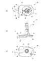
図10は、このようなシャフト部の構成を示した図で、(a)は上面図、(b)は側面図、(c)は底面図である。図10において、シャフト部30のシャフトホルダー31の裏面にはたとえば三つのネジ螺入孔34が形成され、図示しないミラーベースに形成されたネジ挿入孔から挿入されたネジが該ネジ螺入孔34に螺入されることによって、シャフトホルダー31とミラーベースとの固定を図っている。なお、図10は本発明の実施態様である図1に対応させて描いた図であり、上述した構成以外の説明については図1における説明を参照されたい。
FIGS. 10A and 10B are diagrams showing the configuration of such a shaft portion, where FIG. 10A is a top view, FIG. 10B is a side view, and FIG. 10C is a bottom view. In FIG. 10, for example, three
このため、シャフト部30のミラーベースに対する取り付けを強固なものとする場合、ネジの数を多くしなければならず、それに応じて、シャフト部30のミラーベースに対する取り付けが煩雑になるという不都合を有していた。
For this reason, when the attachment of the
また、図10に示すように、シャフト部30の貫通孔33に挿入されるハーネス40は、ミラーベースに対するシャフトホルダー31のネジによる固定部の近傍を通過して車両側に引き回されるように配置されるようになっている。このため、シャフト部30のミラーベースに対する取り付けの際に、往々にして、ハーネス40が該ネジによって挟み込まれ損傷を起こしてしまう不都合を有していた。
Further, as shown in FIG. 10, the
本発明は、このような事情に鑑みなされたものであり、その目的は、シャフト部のミラーベースに対する取り付けを極めて容易にできる車両用ミラーを提供するにある。 The present invention has been made in view of such circumstances, and an object thereof is to provide a vehicle mirror that can very easily attach a shaft portion to a mirror base.
また、本発明の目的は、シャフト部のミラーベースに対する取り付けの際に、ハーネスに損傷を与えることのない車両用ミラーを提供するにある。 Another object of the present invention is to provide a vehicle mirror that does not damage the harness when the shaft portion is attached to the mirror base.
このような目的を達成させるために、本発明は、シャフト部のミラーベースに対する取り付けを、ネジによる固定と、たとえばシャフトホルダーに設けた差し込み爪をミラーベースに設けた差し込み孔に挿入させる係合による固定とを併用させて行うようにしたものである。また、本発明は、ミラーベースとシャフト部との係合を行う部分を、ハーネスをミラーベースからシャフト部へ導入させる側に位置づけるようにしたものである。 In order to achieve such an object, the present invention is based on fixing the shaft portion to the mirror base by fixing with screws and engaging the insertion claw provided on the shaft holder into the insertion hole provided on the mirror base, for example. It is designed to be performed in combination with fixation. In the present invention, the portion where the mirror base and the shaft portion are engaged is positioned on the side where the harness is introduced from the mirror base to the shaft portion.
本発明は、以下の構成によって把握される。
(1)本発明の車両用ミラーは、車両に取り付けられたミラーベースと、前記ミラーベースにシャフト部を介して取り付けられるとともに前記シャフト部の周りに回動できるミラー本体とを備え、前記シャフト部は、前記ミラーベースに固定されるシャフトホルダーと、このシャフトホルダーに植設されるシャフトとから構成される車両用ミラーであって、
前記シャフトホルダーと前記ミラーベースとの固定は、前記シャフトホルダーと前記ミラーベースのうち一方に設けた差し込み爪の他方に設けた差し込み孔への挿入による係合と、ネジの前記シャフトホルダーと前記ミラーベースのうち一方に設けたネジ挿入孔を通して他方に設けたネジ螺入孔への螺入による固定によってなされていることを特徴とする。
(2)本発明の車両用ミラーは、(1)の構成において、前記シャフト部は、前記シャフトホルダーとともに前記シャフトの中心軸に沿って設けられた貫通孔に、前記車両側から前記ミラー本体へ引き回されるハーネスが挿入されて構成され、
前記シャフトホルダーの前記シャフトを間にして相対向するそれぞれの領域を第1領域および第2領域とした場合、前記第1領域は前記ハーネスが前記ミラーベースから前記シャフト部へ導入される側となっており、この第1領域には前記差し込み爪あるいは差し込み孔が形成され、前記第2領域には、前記ネジ挿入孔あるいはネジ螺入孔が形成されていることを特徴とする。
(3)本発明の車両用ミラーは、(1)の構成において、前記ミラーベースに前記シャフトホルダーを埋設させる嵌合凹部が形成され、前記差し込み孔あるいは前記差し込み爪は、前記嵌合凹部の壁面部に形成されていることを特徴とする。
The present invention is grasped by the following composition.
(1) A vehicle mirror according to the present invention includes a mirror base attached to a vehicle, and a mirror body attached to the mirror base via a shaft portion and rotatable around the shaft portion. Is a vehicle mirror composed of a shaft holder fixed to the mirror base and a shaft implanted in the shaft holder,
The shaft holder and the mirror base are fixed by engaging with an insertion hole provided on the other of the insertion claws provided on one of the shaft holder and the mirror base, and the shaft holder of the screw and the mirror. It is characterized by being fixed by screwing into a screw insertion hole provided in the other through a screw insertion hole provided in one of the bases.
(2) In the vehicle mirror of the present invention, in the configuration of (1), the shaft portion is inserted into a through hole provided along the central axis of the shaft together with the shaft holder from the vehicle side to the mirror body. The harness to be routed is inserted and configured,
When the regions of the shaft holder that face each other with the shaft therebetween are defined as a first region and a second region, the first region is a side where the harness is introduced from the mirror base to the shaft portion. In the first area, the insertion claw or insertion hole is formed, and in the second area, the screw insertion hole or screw screw hole is formed.
(3) In the vehicle mirror of the present invention, in the configuration of (1), a fitting recess for embedding the shaft holder in the mirror base is formed, and the insertion hole or the insertion claw is a wall surface of the fitting recess. It is formed in the part.
このように構成された車両用ミラーによれば、シャフト部のミラーベースに対する取り付けを極めて容易にできるようになる。また、シャフト部のミラーベースに対する取り付けの際に、ハーネスに損傷を与えるようなことがなくなる。 According to the vehicle mirror configured as described above, the shaft portion can be extremely easily attached to the mirror base. In addition, the harness is not damaged when the shaft portion is attached to the mirror base.
以下、添付図面を参照して、本発明を実施するための形態(以下、実施形態)について詳細に説明する。なお、実施形態の説明の全体を通して同じ要素には同じ番号を付している。 DESCRIPTION OF EMBODIMENTS Hereinafter, embodiments for carrying out the present invention (hereinafter referred to as embodiments) will be described in detail with reference to the accompanying drawings. Note that the same number is assigned to the same element throughout the description of the embodiment.
(実施態様1)
図2は、本発明の車両用ミラーをたとえばドアミラーを一例として示した概略構成図である。図2に示すドアミラーはたとえば運転手側(走行方向右側)のドアに取り付けられドアミラーを一部破断して示している。
(Embodiment 1)
FIG. 2 is a schematic configuration diagram showing the vehicle mirror of the present invention, for example, a door mirror. The door mirror shown in FIG. 2 is attached to a door on the driver side (traveling direction right side), for example, and the door mirror is partially cut away.
図2において、まず、車両10に取り付けられたミラーベース11がある。このミラーベース11は車両10の外方へ突出するように形成され、このミラーベース11には、ミラー本体20が取り付けられている。ミラー本体20は、ミラー21とこのミラー21を保持するミラー筐体22とから構成されている。
In FIG. 2, first, there is a
ミラーベース11に対するミラー本体20の取り付けは、ミラーベース11に固定されたシャフト部30のシャフト32がミラー筐体22に形成された軸受23に挿入されることによってなされている。これにより、ミラー本体20は該シャフト部30の周りに一定の角度範囲内で図中矢印方向Aに回動できるようになっている。ミラー本体20の該シャフト部30の周りの回動は、たとえば、ミラー筐体22に内蔵された電動駆動機構(図示せず)によってなされるようになっている。
The mirror
シャフト部30は、ミラーベース11に直接に固定されるシャフトホルダー31と、このシャフトホルダー31に植設されて形成されるシャフト32とから構成されている。ミラーベース11に対するシャフトホルダー31の固定については後に詳述する。シャフト部30は、シャフトホルダー31とともにシャフト32の中心軸に沿って設けられた貫通孔33が形成されている。シャフト部30の貫通孔33はハーネス40が配置されている。ハーネス40は、車両10側からシャフト部30の貫通孔33に挿入されてミラー筐体22内に引き回されている。ハーネス40はミラー筐体22内の前記電動駆動機構(図示せず)に電気的に接続され、ハーネス40を介して車両10側から前記電動駆動機構を駆動でき、ミラー本体20をミラーベース11に対して回動できるようになっている。
The
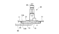
図1は、シャフト部30の構成を示す図である。図1(a)は上面図、図1(b)は側面図、図1(c)は底面図である。
FIG. 1 is a diagram illustrating a configuration of the
図1において、シャフト部30は、上述したように、シャフトホルダー31とシャフト32とからなり、これらシャフトホルダー31とシャフト32にはシャフト32の中心軸に沿って貫通孔33が形成されて構成されている。
In FIG. 1, as described above, the
シャフトホルダー31には、ミラーベース11との固定がなされる固定部が形成されている。この固定部は、たとえば一つのネジによってミラーベース11との固定を行う固定部と、たとえば二つの係合手段によってミラーベース11との固定を行う固定部によって構成されている。
The
ネジによる固定部は、図1(b)、(c)に示すように、シャフトホルダー31の裏面において形成されるネジ螺入孔34によって構成されている。また、係合手段による固定部は、図1(a)、(b)、(c)に示すように、シャフトホルダー31の周縁において外方に突出して形成される差し込み爪35によって構成されている。差し込み爪35は、図1(a)のIII−III線における断面である図3に示すように、シャフトホルダー31の厚さよりも薄く形成され、差し込み爪35の表面はシャフトホルダー31の表面に対して段差(図中符号Eで示す)を有するようになっている。これにより、差し込み爪35は、ミラーベース11に形成された後述の差し込み孔14にガタなく、しかもシャフト部30がミラーベース11に対して浮きがなく挿入できるようにするためである。
As shown in FIGS. 1 (b) and 1 (c), the fixing portion by the screw is configured by a
ここで、シャフトホルダー31のシャフト32を間にして相対向するそれぞれの領域をP領域(第1領域)およびQ領域(第2領域)とした場合、差し込み爪35が形成される領域はP領域となっており、ネジ螺入孔34が形成される領域はQとなっている。P領域はハーネス40がミラーベース11からシャフト部30へ導入される側の領域となり、このP領域において、係合手段による固定手段を形成するようにし、ネジによる固定手段を形成することを回避するようになっている。これにより、シャフト部30のミラーベース11に対する取り付けの際にハーネス40が該ネジによって挟み込まれ損傷を起こしてしまう不都合を回避できるようになっている。
Here, when the regions facing each other with the
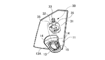
図4は、上述したシャフト部30をミラーベース11に固定させる手前の状態を示した斜視図である。
FIG. 4 is a perspective view showing a state before the
ミラーベース11には、シャフト部30が固定される領域において、嵌合凹部13が形成されている。シャフト部30のシャフトホルダー31が嵌合凹部13に埋設されるようにし、シャフト部30のミラーベース11に対する位置決めを容易にできるようになっている。ミラーベース11の嵌合凹部13は、少なくともシャフト部30の差し込み爪35が形成された側において、側壁面13Aを有し、この側壁面13Aには、前記差し込み爪35が挿入される差し込み孔14が形成されている。これにより、シャフト部30は、シャフトホルダー31に形成された差し込み爪35をミラーベース11の嵌合凹部13に形成された差し込み孔14に挿入させながら、シャフトホルダー31を嵌合凹部13に埋設させて配置させることができる。
A
なお、図4において、嵌合凹部13の側壁面13Aには、たとえば二つの差し込み孔14の間にハーネス挿入孔15が形成されている。車両10側から引き回されるハーネス40(図1参照)はハーネス挿入孔15を通してシャフト部30の貫通孔33に導入されるようになっている。このように嵌合凹部13の側壁面13Aにハーネス挿入孔15を形成することによって、車両10側からのハーネス40を、シャフト部30とミラーベース11とのネジからなる固定手段側からではなく、差し込み爪35および差し込み孔14からなる固定手段側から確実に導入させることができる効果を奏する。なお、図4では、差し込み孔14とハーネス挿入口15はそれぞれ別個の孔として構成したものである。しかし、たとえば横に長い長孔からなるハーネス挿入口を形成し、このハーネス挿入口にシャフトホルダー31の差し込み爪35を挿入できるように構成するようにしてもよい。すなわち、前記長孔において、ハーネス挿入口15と差し込み孔14とを兼用させるように構成してもよい。
In FIG. 4, a
図5は、シャフト部30がミラーベース11に固定されている状態を示した側面図である。なお、図5は、シャフト部30のミラーベース11への固定を容易に理解できるようにミラーベース11を断面図として示している。
FIG. 5 is a side view showing a state in which the
図5に示すように、シャフト部30は、シャフトホルダー31に形成された差し込み爪35がミラーベース11の嵌合凹部13に形成された差し込み孔14に挿入された状態で、シャフトホルダー31が嵌合凹部13内に配置されている。 なお、差し込み孔14の形状は、差し込み爪35の断面の形状よりも若干大きな程度に形成され、これにより、シャフト部30はミラーベース11に対するガタをなくすとともに、ミラーベース11に対するシャフト部30の浮きをなくせるようになっている。
As shown in FIG. 5, the
そして、図中αで示す個所において、図6に示すように、シャフト部30のシャフトホルダー31は、ネジ50によってミラーベース11に固定されるようになっている。すなわち、ネジ50は、ミラーベース11に形成されたネジ挿入孔16に挿入され、シャフトホルダー31に形成された前記ネジ螺入孔34に螺入されることによって、シャフトホルダー31とミラーベース11との固定を図っている。なお、シャフトホルダー31のミラーベース11に対するネジの固定は、必ずしも図6に示す場合に限定されることはなく、図7に示すように、シャフトホルダー31側から挿入されるネジ51によって行うようにしてもよい。すなわち、図7において、ネジ51は、シャフトホルダー31に形成されたネジ挿入孔37に挿入され、ミラーベース11に形成されたネジ螺入孔18に螺入されることによって、シャフトホルダー31とミラーベース11との固定を図っている。
Then, at a position indicated by α in the figure, as shown in FIG. 6, the
このように構成したシャフト部30のミラーベース11に対する固定は、ネジ50によって行うとともに、係合手段(差し込み爪35、差し込み孔14)によって行っていることから、ネジの数を低減させることができ、シャフト部30のミラーベース11に対する取り付けを極めて容易にできる。
The
また、シャフト部30のミラーベース11に対する係合手段が設けられる側は、ハーネス40がミラーベース11からシャフト部30へ導入される側となっていることから、シャフト部30のミラーベース11に対する取り付けの際に、ハーネス40がネジ50によって挟み込まれ損傷を起こしてしまう不都合を回避できるようになる。
Further, the side on which the engaging means for the
(実施態様2)
実施態様1では、車両10側から引き回されるハーネス40は、シャフトホルダー31を埋設するミラーベース11の嵌合凹部13の側壁面13Aに形成したハーネス挿入孔15を通してシャフト部30側へ導入させるように構成したものである。しかし、ハーネス挿入孔15は、嵌合凹部13の側壁面13Aに形成されることはなく、図8に示すように、嵌合凹部13の底面に形成されていてもよい。
(Embodiment 2)
In Embodiment 1, the
図8は、図5に対応づけて描いた図である。図8において、図5の場合と比較して異なる構成は、ミラーベース11にあり、このミラーベース11の嵌合凹部13の底面13Bにはハーネス挿入孔15が設けられ、このハーネス挿入孔15を通して車両10側からのハーネス40はシャフト部30側へ導入されるようになっている。
FIG. 8 is a diagram drawn in association with FIG. In FIG. 8, the
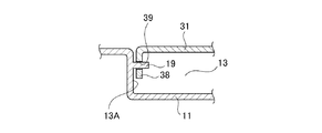
(実施態様3)
実施態様1では、シャフト部30のミラーベース11への係合は、シャフトホルダー31に形成された差し込み爪35をミラーベース11の嵌合凹部13に形成された差し込み孔14に挿入させるようにしたものである。しかし、これに限定されることはなく、図9に示すように、ミラーベース11の嵌合凹部13に形成された差し込み爪をシャフトホルダー31に形成された差し込み孔に挿入させるようにしてもよい。
(Embodiment 3)
In Embodiment 1, the
図9は、ミラーベース11の嵌合凹部13と、この嵌合凹部13に埋設されるシャフトホルダー31を示している。図9において、嵌合凹部13の側壁面13Aには嵌合凹部13側へ突出する差し込み爪19が形成されている。また、シャフトホルダー31の周縁は、嵌合凹部13の側壁面13Aと対向する屈曲部38が形成され、この屈曲部38に前記差し込み爪19が挿入される差し込み孔39が形成されている。
FIG. 9 shows the
なお、上述したハーネス40は、ミラー本体20をミラーベース11に対して電動で回動させるための配線束として説明したものである。しかし、これに限定されることはない。たとえば、ミラー本体20には、ターンランプ、フットランプ等のランプ、あるいは露結を防止するためのヒータを内蔵させる構成とし、この場合において、ハーネス40は該ランプあるいはヒータを駆動させるための配線束として用いるようにしてもよい。
The
また、上述した実施態様では、シャフト部30のミラーベース11に対する固定を、たとえばネジを一つ、係合手段(差し込み爪、差し込み孔)を二つとしたものであるが、これらの数に限定されないことはいうまでもない。係合手段(差し込み爪、差し込み孔)を併用させることにより、その分のネジの数を低減できるからである。
Further, in the above-described embodiment, the
以上、実施形態を用いて本発明を説明したが、本発明の技術的範囲は上記実施形態に記載の範囲には限定されないことは言うまでもない。上記実施形態に、多様な変更または改良を加えることが可能であることが当業者に明らかである。またその様な変更または改良を加えた形態も本発明の技術的範囲に含まれ得ることが、特許請求の範囲の記載から明らかである。 As mentioned above, although this invention was demonstrated using embodiment, it cannot be overemphasized that the technical scope of this invention is not limited to the range as described in the said embodiment. It will be apparent to those skilled in the art that various modifications or improvements can be added to the above-described embodiments. Further, it is apparent from the scope of the claims that the embodiments added with such changes or improvements can be included in the technical scope of the present invention.
10……車両、11……ミラーベース、13……嵌合凹部、13A……側壁面、13B……底面、14……差し込み孔、15……ハーネス挿入孔、16……ネジ挿入孔、18……ネジ螺入孔、19……差し込み爪、20……ミラー本体、21……ミラー、22……ミラー筐体、23……軸受け、30……シャフト部、31……シャフトホルダー、32……シャフト、33……貫通孔、34……ネジ螺入孔、35……差し込み爪、37……ネジ挿入孔、38……屈曲部、39……差し込み孔、40……ハーネス、50、51……ネジ。
DESCRIPTION OF
Claims (3)
前記シャフトホルダーと前記ミラーベースとの固定は、前記シャフトホルダーと前記ミラーベースのうち一方に設けた差し込み爪の他方に設けた差し込み孔への挿入による係合と、ネジの前記シャフトホルダーと前記ミラーベースのうち一方に設けたネジ挿入孔を通して他方に設けたネジ螺入孔への螺入による固定によってなされていることを特徴とする車両用ミラー。 A mirror base attached to a vehicle, and a mirror body attached to the mirror base via a shaft portion and rotatable around the shaft portion, wherein the shaft portion is fixed to the mirror base. And a vehicle mirror composed of a shaft installed in the shaft holder,
The shaft holder and the mirror base are fixed by engaging with an insertion hole provided on the other of the insertion claws provided on one of the shaft holder and the mirror base, and the shaft holder of the screw and the mirror. A vehicle mirror characterized by being fixed by screwing into a screw screw hole provided on the other through a screw insertion hole provided on one of the bases.
前記シャフトホルダーの前記シャフトを間にして相対向するそれぞれの領域を第1領域および第2領域とした場合、前記第1領域は前記ハーネスが前記ミラーベースから前記シャフト部へ導入される側となっており、この第1領域には前記差し込み爪あるいは差し込み孔が形成され、前記第2領域には、前記ネジ挿入孔あるいはネジ螺入孔が形成されていることを特徴とする請求項1に記載の車両用ミラー。 The shaft portion is configured by inserting a harness routed from the vehicle side to the mirror main body into a through hole provided along the central axis of the shaft together with the shaft holder,
When the regions of the shaft holder that face each other with the shaft therebetween are defined as a first region and a second region, the first region is a side where the harness is introduced from the mirror base to the shaft portion. 2. The insertion claw or insertion hole is formed in the first area, and the screw insertion hole or screw insertion hole is formed in the second area. Vehicle mirrors.
Priority Applications (1)
| Application Number | Priority Date | Filing Date | Title |
|---|---|---|---|
| JP2011072656A JP2012206568A (en) | 2011-03-29 | 2011-03-29 | Vehicle mirror |
Applications Claiming Priority (1)
| Application Number | Priority Date | Filing Date | Title |
|---|---|---|---|
| JP2011072656A JP2012206568A (en) | 2011-03-29 | 2011-03-29 | Vehicle mirror |
Publications (1)
| Publication Number | Publication Date |
|---|---|
| JP2012206568A true JP2012206568A (en) | 2012-10-25 |
Family
ID=47186719
Family Applications (1)
| Application Number | Title | Priority Date | Filing Date |
|---|---|---|---|
| JP2011072656A Pending JP2012206568A (en) | 2011-03-29 | 2011-03-29 | Vehicle mirror |
Country Status (1)
| Country | Link |
|---|---|
| JP (1) | JP2012206568A (en) |
Citations (2)
| Publication number | Priority date | Publication date | Assignee | Title |
|---|---|---|---|---|
| JPS62156052U (en) * | 1986-03-27 | 1987-10-03 | ||
| JPH0280043U (en) * | 1988-12-08 | 1990-06-20 |
-
2011
- 2011-03-29 JP JP2011072656A patent/JP2012206568A/en active Pending
Patent Citations (2)
| Publication number | Priority date | Publication date | Assignee | Title |
|---|---|---|---|---|
| JPS62156052U (en) * | 1986-03-27 | 1987-10-03 | ||
| JPH0280043U (en) * | 1988-12-08 | 1990-06-20 |
Similar Documents
| Publication | Publication Date | Title |
|---|---|---|
| JP2006298351A (en) | Wiper connector cap | |
| JP2012206568A (en) | Vehicle mirror | |
| CN101712300B (en) | A rear-view mirror device for vehicle | |
| JP2006281966A (en) | Mounting structure of on-vehicle mounting part | |
| JP2016081721A (en) | Wire harness | |
| JP5467613B2 (en) | Mirror body support structure | |
| JP6670027B2 (en) | Harness holding structure | |
| JP2010143535A (en) | Bracket mounting structure on steering column | |
| JP2012206567A (en) | Door mirror | |
| JP3997784B2 (en) | Vehicle door mirror | |
| JP4595552B2 (en) | Connector connection structure to circuit board | |
| JP6310770B2 (en) | Vehicle side mirror | |
| JP2005243348A (en) | Circuit breaker housing | |
| JP2008021425A (en) | Grommet | |
| JP2006194557A (en) | Air conditioner | |
| KR100681951B1 (en) | Structure of wiring harness clip | |
| KR200430357Y1 (en) | Device of fixing terminal | |
| KR20070059358A (en) | Structure | |
| JP2007132590A (en) | Outdoor unit for air conditioner | |
| JP4802137B2 (en) | Meter device mounting structure | |
| JP2007331735A (en) | Rear spoiler device and its manufacturing method | |
| JP3669484B2 (en) | Battery | |
| JP2006240382A (en) | Wiring structure of wire harness for automobile door | |
| JP2010105458A (en) | Connector unit for lighting system mounted on side-view mirror for automobile | |
| KR200395501Y1 (en) | A rearview mirror for cars |
Legal Events
| Date | Code | Title | Description |
|---|---|---|---|
| A621 | Written request for application examination |
Free format text: JAPANESE INTERMEDIATE CODE: A621 Effective date: 20131011 |
|
| A977 | Report on retrieval |
Free format text: JAPANESE INTERMEDIATE CODE: A971007 Effective date: 20140724 |
|
| A131 | Notification of reasons for refusal |
Free format text: JAPANESE INTERMEDIATE CODE: A131 Effective date: 20140812 |
|
| A02 | Decision of refusal |
Free format text: JAPANESE INTERMEDIATE CODE: A02 Effective date: 20141216 |