JP2012206430A - Laminated film - Google Patents
Laminated film Download PDFInfo
- Publication number
- JP2012206430A JP2012206430A JP2011074634A JP2011074634A JP2012206430A JP 2012206430 A JP2012206430 A JP 2012206430A JP 2011074634 A JP2011074634 A JP 2011074634A JP 2011074634 A JP2011074634 A JP 2011074634A JP 2012206430 A JP2012206430 A JP 2012206430A
- Authority
- JP
- Japan
- Prior art keywords
- layer
- laminated film
- thickness
- ultraviolet
- film
- Prior art date
- Legal status (The legal status is an assumption and is not a legal conclusion. Google has not performed a legal analysis and makes no representation as to the accuracy of the status listed.)
- Withdrawn
Links
Landscapes
- Laminated Bodies (AREA)
- Protection Of Plants (AREA)
Abstract
Description
本発明は、赤外線反射性能、耐擦過性能および紫外線カット性能に優れ、農業用に好適な積層フィルムに関するものである。 The present invention relates to a laminated film which is excellent in infrared reflection performance, abrasion resistance performance and ultraviolet cut performance and is suitable for agriculture.
農業用ハウスなどの温室栽培に用いる農業用フィルムには、植物の生育に必要となる太陽光(特に可視光線)を効率良く取り入れるとともに、ハウス栽培において、栽培コストの多くを占める暖房費を削減するため、暖房熱である遠赤外線を反射し、暖房効率を高めることが必要とされる。また、夏季において、農業用ハウスは日中の高温・多湿時に被覆材の裾を上げ、夕方外気温度が低下する前に裾を下げて温湿度の調節を行う。よって、被覆材として使用される農業用フィルムには、ハウス支柱との摩擦により傷がつかないよう高い耐擦過性が必要となる。さらに、屋外で長期間使用するため紫外線に対する耐久性も必要となる。 Agricultural films used for greenhouse cultivation, such as agricultural houses, efficiently incorporate sunlight (particularly visible light) necessary for plant growth, and reduce heating costs that occupy much of the cultivation costs in house cultivation. Therefore, it is necessary to reflect far-infrared rays that are heating heat and to improve heating efficiency. Also, in summer, agricultural houses raise the skirt of the covering material at high temperatures and humidity during the day, and adjust the temperature and humidity by lowering the skirt before the outdoor air temperature drops in the evening. Therefore, the agricultural film used as the covering material needs to have high scratch resistance so as not to be damaged by friction with the house support. Furthermore, since it is used outdoors for a long time, durability against ultraviolet rays is also required.
しかし、上述した農業用フィルムの要求性能、つまり、可視光透過性能、遠赤外線反射性能に優れ、かつ、耐擦過性、紫外線カット性等の耐久性能を備えた農業用フィルムが存在しないのが実状である。 However, there is no agricultural film with the required performance of the above-mentioned agricultural film, that is, excellent in visible light transmission performance and far-infrared reflection performance, and having durability such as scratch resistance and UV-cutting properties. It is.
例えば、ポリエチレン/酢酸ビニル共重合体からなるフィルムに遠赤外線吸収剤を配合した透光率80%以上の農業用被覆材が提案されている(特許文献1参照)。しかし、本方法では植物の生育に必要となる可視光線は充分透過するものの、暖房熱である遠赤外線を吸収し反射しないため、充分な保温効果を得る事ができない。また、ポリエチレン/酢酸ビニル共重合体等の合成樹脂は、
耐擦過性には優れるものの、樹脂中に紫外線吸収剤等の耐候性助剤を添加した場合においても、その耐候性は充分では無く、長期間の屋外使用に耐えることができないと推定される。
For example, an agricultural covering material having a transmissivity of 80% or more in which a far infrared absorber is blended with a film made of a polyethylene / vinyl acetate copolymer has been proposed (see Patent Document 1). However, in this method, visible light necessary for plant growth is sufficiently transmitted, but far infrared rays as heating heat is absorbed and not reflected, so that a sufficient heat retaining effect cannot be obtained. Synthetic resins such as polyethylene / vinyl acetate copolymer are
Although excellent in scratch resistance, even when a weathering aid such as an ultraviolet absorber is added to the resin, the weather resistance is not sufficient, and it is estimated that the resin cannot withstand long-term outdoor use.
また、プラスチックフィルムの片面に銀蒸着層を形成し、その上に銀蒸着層を保護し、耐擦過性能を付与するため腐食防止層を形成し、反対面に紫外線カット層を形成した耐久性反射フィルムが提案されている(特許文献2)。しかし、本方法は屋外使用に長期間耐えうる耐候性は有しているが、可視光透過性能、遠赤外線反射性能、耐擦過性能の全てを高いレベルで発現させることが困難である。例えば、遠赤外線反射性能を高めるためには、遠赤外線を反射する銀蒸着層の膜厚を厚くし、遠赤外線を吸収する腐食防止層の膜厚を薄くする必要がある。しかし、この場合は銀蒸着層が厚くなったことにより可視光透過性能が低下し、腐食防止層が薄くなることにより耐擦過性能が低下してしまう。逆に可視光透過性能を高めるため銀蒸着層を薄くし、耐擦過性能を高めるため腐食防止層を厚くした場合、遠赤外線反射性能が低下してしまう。 Also, a durable reflective film in which a silver vapor deposition layer is formed on one side of a plastic film, a silver vapor deposition layer is protected on it, a corrosion prevention layer is formed to provide scratch resistance, and an ultraviolet cut layer is formed on the opposite surface A film has been proposed (Patent Document 2). However, although this method has weather resistance that can withstand outdoor use for a long time, it is difficult to express all of visible light transmission performance, far-infrared reflection performance, and abrasion resistance performance at a high level. For example, in order to improve the far-infrared reflection performance, it is necessary to increase the film thickness of the silver vapor deposition layer that reflects far-infrared light and to decrease the film thickness of the corrosion prevention layer that absorbs far-infrared light. However, in this case, the visible light transmission performance is lowered due to the thick silver deposition layer, and the abrasion resistance performance is lowered due to the thin corrosion prevention layer. On the other hand, when the silver vapor deposition layer is made thin in order to improve the visible light transmission performance, and the corrosion prevention layer is made thick in order to improve the abrasion resistance performance, the far infrared reflection performance is lowered.
本発明は、かかる従来技術の背景に鑑み、遠赤外線反射性能、耐擦過性能全てを高いレベルで発現し、農業用に好適なフィルムを提供せんとするものである。 In view of the background of such prior art, the present invention is intended to provide a film suitable for agriculture, exhibiting far-infrared reflection performance and abrasion resistance performance at a high level.
本発明は、かかる課題を解決するために、次のような手段を採用するものである。すなわち、本発明のフィルムは、以下の構成からなる。
(1)合成樹脂からなる基材の片面に金属層/カーボン層/ハードコート層を順に形成し、当該基材の他の片面に紫外線カット層を形成したことを特徴とする積層フィルム。
(2)ハードコート層が硬化した樹脂からなるものである前記積層フィルム。
(3)ハードコート層の厚みが0.5〜1μmであることを特徴とする前記いずれかの積層フィルム。
(4)紫外線カット層が波長280〜400nmの紫外線の電磁波に対して平均50%以上の遮断性能を有するものである前記いずれかの積層フィルム。
(5)金属層が、銀を主成分とする遠赤外線反射層と誘電体層からなる多層構造であることを特徴とする前記いずれかの積層フィルム。
(6)基材と前記金属層の間にアンダーコート層を形成したことを特徴とする前記いずれかの積層フィルム。
(7)金属層の厚みが5〜20nm、カーボン層の厚みが1〜20nm、紫外線カット層が波長315〜400nmの電磁波を各波長において70%以上遮断するものである前記いずれかの積層フィルム。
(8)農業用である前記いずれかの積層フィルム。
The present invention employs the following means in order to solve such problems. That is, the film of the present invention has the following configuration.
(1) A laminated film in which a metal layer / carbon layer / hard coat layer is formed in order on one side of a base material made of a synthetic resin, and an ultraviolet cut layer is formed on the other side surface of the base material.
(2) The laminated film, which is made of a cured resin.
(3) The laminated film according to any one of the above, wherein the hard coat layer has a thickness of 0.5 to 1 μm.
(4) The laminated film according to any one of the above, wherein the ultraviolet cut layer has an average of 50% or more blocking performance against ultraviolet electromagnetic waves having a wavelength of 280 to 400 nm.
(5) The laminated film according to any one of the above, wherein the metal layer has a multilayer structure comprising a far-infrared reflective layer mainly composed of silver and a dielectric layer.
(6) The laminated film according to any one of the above, wherein an undercoat layer is formed between a base material and the metal layer.
(7) The laminated film according to any one of the above, wherein the metal layer has a thickness of 5 to 20 nm, the carbon layer has a thickness of 1 to 20 nm, and the ultraviolet cut layer blocks 70% or more of electromagnetic waves having wavelengths of 315 to 400 nm at each wavelength.
(8) Any one of the above laminated films for agriculture.
本発明によれば、可視光透過性能、遠赤外線反射性能、耐擦過性能の全てを高いレベルで発現し、屋外で長期間使用可能な耐候性を有する農業用に好適なフィルムを提供することができる。 According to the present invention, it is possible to provide a film suitable for agriculture that exhibits all of visible light transmission performance, far-infrared reflection performance, and abrasion resistance performance at a high level and has weather resistance that can be used outdoors for a long period of time. it can.
本発明の積層フィルムは、合成樹脂からなる基材の片面に金属層/カーボン層/ハードコート層を順に形成し、当該基材の他の片面に紫外線カット層を形成することが必須である。本発明で用いる基材は、可視光透過性能、耐候性に優れていれば特に限定されることはないが、例えばポリエチレンテレフタレート、ポリカーボネート、アクリル、ナイロンなどが好ましく、いずれもコロナ処理、プラズマ処理、ケン化などの表面処理を施したり、易接着層を形成したものであっても良い。基材の厚みについては、特に制限はなく、用途、使用年数により使い分ければ良いが、農業用フィルムとして展張した場合の取扱い性、機械的強度、耐熱性等の点から10〜150μmであることが好ましく、さらに好ましくは20〜100μmである。 In the laminated film of the present invention, it is essential to sequentially form a metal layer / carbon layer / hard coat layer on one side of a base material made of a synthetic resin and to form an ultraviolet cut layer on the other side of the base material. The substrate used in the present invention is not particularly limited as long as it has excellent visible light transmission performance and weather resistance, but for example, polyethylene terephthalate, polycarbonate, acrylic, nylon and the like are preferable, and all are corona treatment, plasma treatment, A surface treatment such as saponification or an easily adhesive layer may be formed. The thickness of the base material is not particularly limited and may be properly selected depending on the application and the years of use, but it should be 10 to 150 μm from the viewpoint of handleability, mechanical strength, heat resistance, etc. when spread as an agricultural film. Is more preferable, and it is 20-100 micrometers.
金属層は遠赤外線反射性能を発現し、金属を含有する層である。金属層については、電気伝導度が高い物質ほど遠赤外線反射性能に優れるという観点から、一般的な金属のうち電気伝導度が高い銀、銅、金等の金属の1種またはこれを含むまたはその他の金属を2種以上含む合金を使用することが好ましい。このうち、電気伝導度が最も高い銀を金属層に使用することがより好ましいことである。さらに、銀が大気中の硫黄、酸素などによって腐食することを抑制するため、金等の耐腐食性に優れる金属を混合し、合金化することも好ましい使用態様である。厚みは特に制限はないが、必要とする遠赤外線反射性能と可視光透過性能を考慮し、5〜20nmの範囲で適宜選択することが好ましい。厚みが低いと可視光透過性能は高い値を示すが、遠赤外線反射性能が低下してしまう。逆に厚すぎると透明性が低下し、植物の生育に必要である可視光透過性能が得られないばかりか、金属の使用量が増加し経済的にも好ましくない。金属層は上述した遠赤外線反射性能を発現する層(以下、遠赤外線反射層とする)の単層構造としても良いが、遠赤外線反射層の上に誘電体層を積層したり、遠赤外線反射層を誘電体層でサンドイッチした多層構造であっても良い。本発明における誘電体層は、透明で屈折率の高い誘電体からなる層であり、例えば、酸化チタン、酸化亜鉛、錫ドープ酸化インジウム(ITO)等の金属酸化物を挙げることができる。これら誘電体層を形成することにより可視光透過性能が向上するため、植物の生育上好ましいことである。誘電体層の厚みについては、10〜100nmであることが好ましく、さらに好ましくは30〜60nmである。誘電体層の厚みが小さいと可視光透過性能の大幅な向上は見られない。逆に過大に積層しても可視光透過性能の更なる向上は得られないばかりか、経済的に好ましくない。これら金属層は、真空蒸着法、スパッタリング法、イオンプレーティング法など公知の技術を用い製膜することができる。 The metal layer expresses far-infrared reflection performance and is a layer containing a metal. About a metal layer, it is 1 type of metals, such as silver, copper, gold | metal | money etc. with high electrical conductivity among general metals from a viewpoint that far infrared reflective performance is excellent in the substance with high electrical conductivity, or this is included. It is preferable to use an alloy containing two or more of these metals. Among these, it is more preferable to use silver having the highest electrical conductivity for the metal layer. Furthermore, in order to suppress the corrosion of silver by sulfur, oxygen, etc. in the atmosphere, it is also a preferable usage mode that a metal having excellent corrosion resistance such as gold is mixed and alloyed. Although there is no restriction | limiting in particular in thickness, It is preferable to select suitably in the range of 5-20 nm in consideration of the far-infrared reflective performance and visible light transmission performance which are required. If the thickness is low, the visible light transmission performance shows a high value, but the far-infrared reflection performance decreases. On the other hand, if it is too thick, the transparency is lowered, and not only the visible light transmission performance necessary for plant growth is obtained, but also the amount of metal used is increased, which is not economical. The metal layer may have a single-layer structure of the above-described far-infrared reflective performance layer (hereinafter referred to as a far-infrared reflective layer), but a dielectric layer may be laminated on the far-infrared reflective layer, or a far-infrared reflective layer. A multilayer structure in which layers are sandwiched by dielectric layers may be used. The dielectric layer in the present invention is a layer made of a transparent dielectric material having a high refractive index, and examples thereof include metal oxides such as titanium oxide, zinc oxide, and tin-doped indium oxide (ITO). Forming these dielectric layers improves visible light transmission performance, which is preferable for plant growth. The thickness of the dielectric layer is preferably 10 to 100 nm, and more preferably 30 to 60 nm. If the thickness of the dielectric layer is small, the visible light transmission performance is not significantly improved. On the contrary, even if the layers are excessively laminated, not only the visible light transmission performance can be further improved, but it is economically undesirable. These metal layers can be formed using a known technique such as vacuum deposition, sputtering, or ion plating.
また、基材と金属層の間にアンダーコート層を形成しても良い。アンダーコート層を形成することにより、積層フィルムとしての耐擦過性が向上するため好ましいことである。アンダーコート層を形成する樹脂は、高透明で耐久性があるものであれば特に限定されることはないが、例えば、アクリル系樹脂、ウレタン系樹脂、フッ素系樹脂、シリコン系樹脂などを単独、または混合物として使用することができる。これらアンダーコート層は、グラビアコーティング法、リバースロールコーティング法、ロールコーティング法、ディップコーティング法などの公知の技術で塗布し、乾燥した後、必要に応じて紫外線、電子線などを照射し硬化させることにより形成することができる。アンダーコート層の厚みについては、0.5〜5μmであることが好ましく、1〜3μmであることがより好ましい。アンダーコート層の厚みが0.5μm未満では、基材表面を均一に被覆することができないばかりか、耐擦過性を向上させる効果が得られない。逆に、5μmを超えて形成しても、更なる耐擦過性向上は見られず、経済的にも劣り好ましくない。 Moreover, you may form an undercoat layer between a base material and a metal layer. It is preferable to form the undercoat layer because the scratch resistance as a laminated film is improved. The resin for forming the undercoat layer is not particularly limited as long as it is highly transparent and durable, for example, an acrylic resin, a urethane resin, a fluorine resin, a silicon resin, etc. Or it can be used as a mixture. These undercoat layers are applied by a known technique such as gravure coating, reverse roll coating, roll coating, dip coating, etc., dried, and then cured by irradiation with ultraviolet rays, electron beams, etc. as necessary. Can be formed. About the thickness of an undercoat layer, it is preferable that it is 0.5-5 micrometers, and it is more preferable that it is 1-3 micrometers. When the thickness of the undercoat layer is less than 0.5 μm, not only the surface of the substrate cannot be uniformly coated but also the effect of improving the scratch resistance cannot be obtained. On the other hand, even if the thickness exceeds 5 μm, no further improvement in scratch resistance is observed, which is not preferable because it is economically inferior.
金属層とハードコート層の間に形成するカーボン層は、炭素を主成分とする硬質膜である。ダイヤモンドやグラファイトのように規則的な構造をとる炭素素材も使用できるが、アモルファス構造をとるもののほうが好ましい。かようなカーボン層を設けることにより高い耐擦過性が得られる。明確な理由は不明であるが、無機物である金属層と有機物であるハードコート層の密着性を向上させるためと考えられる。金属層とハードコート層の密着性が向上することにより、薄いハードコート層で高い耐擦過性を発現することができる。つまり、遠赤外線を吸収するハードコート層が薄くなることにより、可視光の透過を妨げる金属層を薄くすることが可能となり、可視光透過性能、遠赤外線反射性能、耐擦過性を高いレベルで発現することができる。また、カーボン層は炭素単体で構成されていても良いが、ハードコート層との密着性を考慮し、ハードコート層の組成に合わせて窒素、水素、酸素等の元素を含有させることは好ましいことである。カーボン層を形成する手段は、スパッタリング法、化学気相成長法など既存の方法で形成することができるが、金属層と合わせてスパッタリング法で形成することは工程短縮、製造コストの点で好ましいことである。カーボン層の厚みは1〜20nm、さらには1〜10nmであることが好ましく、さらに好ましくは1〜5nmである。カーボン層は金属層とハードコート層の密着性を向上させ、耐擦過性を向上させる目的で形成していることから、膜厚が小さいとその効果が弱くなる。また膜厚みが大きいと可視光透過性能が低下することに加え、耐擦過性も低下する傾向がある。 The carbon layer formed between the metal layer and the hard coat layer is a hard film mainly composed of carbon. Carbon materials having a regular structure such as diamond and graphite can be used, but those having an amorphous structure are preferred. By providing such a carbon layer, high scratch resistance can be obtained. Although a clear reason is unknown, it is considered to improve the adhesion between the inorganic metal layer and the organic hard coat layer. By improving the adhesion between the metal layer and the hard coat layer, it is possible to develop high scratch resistance with a thin hard coat layer. In other words, by thinning the hard coat layer that absorbs far-infrared light, it is possible to thin the metal layer that prevents the transmission of visible light, and the visible light transmission performance, far-infrared reflection performance, and abrasion resistance are expressed at a high level. can do. In addition, the carbon layer may be composed of carbon alone, but it is preferable to include elements such as nitrogen, hydrogen, and oxygen in accordance with the composition of the hard coat layer in consideration of adhesion to the hard coat layer. It is. The means for forming the carbon layer can be formed by an existing method such as a sputtering method or a chemical vapor deposition method, but it is preferable to form the carbon layer together with the metal layer by a sputtering method in terms of shortening the process and manufacturing cost. It is. The thickness of the carbon layer is preferably 1 to 20 nm, more preferably 1 to 10 nm, and further preferably 1 to 5 nm. Since the carbon layer is formed for the purpose of improving the adhesion between the metal layer and the hard coat layer and improving the scratch resistance, the effect becomes weak when the film thickness is small. Further, when the film thickness is large, the visible light transmission performance is lowered, and the scratch resistance tends to be lowered.
本発明では、基板上に形成した金属層ならびにカーボン層を保護し、耐擦過性を付与する目的でハードコート層を形成することが必須である。ハードコート層としては樹脂が好ましい。樹脂としては、高透明で耐久性(特に耐擦過性)があるものが好ましい。例えば、アクリル系樹脂、ウレタン系樹脂、フッ素系樹脂、シリコン系樹脂などアンダーコート層と同様の樹脂を単独、または混合物として使用することができる。また、ハードコート層は樹脂の溶液をグラビアコーティング法、リバースロールコーティング法、ロールコーティング法、ディップコーティング法などの方法布し、乾燥する。ハードコート層としては樹脂が架橋されていることが好ましい。紫外線、電子線などを照射し架橋させることができる。また樹脂の高分子の官能基を反応しうる架橋剤を添加して、化学反応により架橋させることができる。層の厚みについては、0.5〜3μmであることが好ましく、0.5〜1μmであることがより好ましい。ハードコート層の厚みが小さいと、必要とする耐擦過性能を得られないことがある。またハードコート層が金属層ならびにカーボン層を均一に被覆することができず、長期使用により金属層およびカーボン層が腐食してしまうことがある。逆に厚い場合、ハードコート層の遠赤外線吸収量が増加し、遠赤外線反射率が低下する傾向がある。 In the present invention, it is essential to form a hard coat layer for the purpose of protecting the metal layer and the carbon layer formed on the substrate and imparting scratch resistance. A resin is preferable as the hard coat layer. As the resin, a resin having high transparency and durability (particularly scratch resistance) is preferable. For example, resins similar to the undercoat layer, such as acrylic resin, urethane resin, fluorine resin, and silicon resin, can be used alone or as a mixture. The hard coat layer is dried by applying a resin solution by a gravure coating method, reverse roll coating method, roll coating method, dip coating method or the like. The hard coat layer is preferably cross-linked with a resin. It can be crosslinked by irradiating with ultraviolet rays, electron beams or the like. Moreover, a crosslinking agent capable of reacting with a functional group of the polymer of the resin can be added and crosslinked by a chemical reaction. About the thickness of a layer, it is preferable that it is 0.5-3 micrometers, and it is more preferable that it is 0.5-1 micrometer. If the thickness of the hard coat layer is small, the required scratch resistance may not be obtained. In addition, the hard coat layer cannot uniformly coat the metal layer and the carbon layer, and the metal layer and the carbon layer may be corroded by long-term use. Conversely, when it is thick, the far-infrared absorption amount of the hard coat layer increases and the far-infrared reflectance tends to decrease.
次に、紫外線カット層は、従来公知の有機系紫外線吸収剤や無機系紫外線遮断剤を混入した塗剤をグラビアコーティング法、リバースロールコーティング法、ロールコーティング法、ディップコーティング法などの公知の技術で塗布することにより形成することができる。本発明で用いる有機系紫外線吸収剤は、特に制限はないが、ベンゾフェノン系、ベンゾトリアゾール系、ベンゾエート系、トリアジン系など各種のものが使用できる。また、無機系紫外線遮断剤としては、例えば酸化亜鉛、酸化チタン、酸化マグネシウム等の微粉末が挙げられる。これら有機系紫外線吸収剤および無機系紫外線遮断剤を混入する塗剤としては、アクリル系樹脂、ウレタン系樹脂、フッ素系樹脂、シリコン系樹脂などが挙げられる。紫外線カット層の紫外線遮断性能としては、波長280〜400nmの紫外線遮断率が平均50%以上であることが好ましく、さらに好ましくは平均70%以上遮断することが好ましい。また波長315〜400nmの紫外線を各波長において70%以上遮断する性能を有することも好ましい態様である。紫外線カット層で紫外線を遮断することにより、耐久性が向上することに加え、農業用として使用した場合、病虫害の忌避に有効で農薬の削減にも繋がり好ましいことである。 Next, the UV cut layer is a known technique such as a gravure coating method, reverse roll coating method, roll coating method, dip coating method, or the like, in which a conventionally known organic UV absorber or inorganic UV blocking agent is mixed. It can be formed by coating. The organic ultraviolet absorber used in the present invention is not particularly limited, but various types such as benzophenone, benzotriazole, benzoate, and triazine can be used. Examples of the inorganic ultraviolet blocking agent include fine powders such as zinc oxide, titanium oxide, and magnesium oxide. Examples of the coating agent in which the organic ultraviolet absorber and the inorganic ultraviolet blocking agent are mixed include acrylic resins, urethane resins, fluorine resins, and silicon resins. As the ultraviolet blocking performance of the ultraviolet cut layer, the ultraviolet blocking rate at a wavelength of 280 to 400 nm is preferably 50% or more on average, more preferably 70% or more on average. Moreover, it is also a preferable aspect to have the capability of blocking 70% or more of ultraviolet light having a wavelength of 315 to 400 nm at each wavelength. In addition to improving durability by blocking ultraviolet rays with an ultraviolet cut layer, when used for agriculture, it is effective in avoiding pest damage and leads to reduction of agricultural chemicals.
本発明の積層フィルムを農業用ハウスに用いる場合において、栽培コストの多くを占める暖房費を削減し、かつ、植物の生育に必要となる可視光を効率良く取り入れるため、遠赤外線反射率、可視光透過率の性能を高いレベルで発現することが好ましく、具体的にはJIS R3106に準じて算出した5.5〜50μmの遠赤外線の反射率が70%以上、400〜780nmの可視光の透過率が50%以上であることが好ましく、遠赤外線の反射率が80%以上、可視光の透過率が60%以上であることが、さらに好ましい。 When the laminated film of the present invention is used in an agricultural house, the far-infrared reflectance, visible light is used in order to reduce the heating cost that occupies most of the cultivation cost and efficiently incorporate visible light necessary for plant growth. It is preferable that the transmittance performance is expressed at a high level. Specifically, the reflectance of 5.5 to 50 μm far infrared rays calculated according to JIS R3106 is 70% or more, and the transmittance of visible light of 400 to 780 nm. Is preferably 50% or more, more preferably far infrared reflectance is 80% or more, and visible light transmittance is 60% or more.
また本発明の積層フィルムは280〜400nmの紫外線遮断率が平均50%以上、好ましくは80%以上、さらには90%以上であることが好ましい。 In addition, the laminated film of the present invention preferably has an average ultraviolet blocking rate of 280 to 400 nm of 50% or more, preferably 80% or more, and more preferably 90% or more.
以下に本発明について、実施例を用いてさらに具体的に説明するが、実施例中に示す特性値の測定・算出方法は次のとおりである。 Hereinafter, the present invention will be described in more detail with reference to examples. The measurement and calculation methods of characteristic values shown in the examples are as follows.
A.評価用試験体の作製
遠赤外線反射率、可視光透過率、耐擦過性の試験に供する試験体の作製方法を以下に示す。
(1)積層フィルムを50mm角にカットする。
(2)前記(1)項でカットしたフィルムの紫外線カット層面の相対する2辺に7.5mm幅の両面テープ(PROSELFNo.539R:株式会社ニトムズ製)を接着する。
(3)前記(2)項で作製したフィルムを50mm角フロートガラス(3mm厚み)に貼合し評価用試験体とする。
A. Preparation of test specimen for evaluation A method for preparing a test specimen for use in tests of far-infrared reflectance, visible light transmittance, and scratch resistance is shown below.
(1) Cut the laminated film into 50 mm squares.
(2) A double-sided tape having a width of 7.5 mm (PROSELF No. 539R: manufactured by Nitoms Co., Ltd.) is bonded to two opposite sides of the ultraviolet cut layer surface of the film cut in the above (1).
(3) The film prepared in the item (2) is bonded to 50 mm square float glass (3 mm thickness) to obtain a test specimen for evaluation.
B.遠赤外線反射率
(1)規格:JIS R3106−1998に準拠
(2)測定方法:(i)分光測光器「IR Prestige−21(株式会社島津製作所製)」、正反射測定ユニット「SRM−8000A(株式会社島津製作所製)」を用い、評価用試験体の波長5〜25μmの分光反射率を測定する。なお、標準板にはAl蒸着鏡を用いる。(ii)前記分光反射率からJIS本文付表3に記載の番号λ1(波長5.5μm)〜λ30(波長50μm)の選定波長における分光反射率を抽出する。なお、λ25(波長25.2μm)〜λ30(波長50μm)の反射率はλ24(波長23.3μm)の値を用いる。(iii)抽出した分光反射率にそれぞれJIS本文付表3に記載のAl蒸着鏡の標準反射率を乗じ、λ1〜λ30の選定波長における評価試験体の反射率とする。(iv)前記反射率の平均値を遠赤外線反射率とする。
(3)測定条件:波長範囲「5〜25μm」アボダイス係数「Happ−Genzel」、積算回数「10回」、分解能「4.0cm−1」。
B. Far-infrared reflectance (1) Standard: Conforms to JIS R3106-1998 (2) Measuring method: (i) Spectrophotometer “IR Prestige-21 (manufactured by Shimadzu Corporation)”, specular reflection measuring unit “SRM-8000A” The spectral reflectance at a wavelength of 5 to 25 μm of the test specimen for evaluation is measured using “manufactured by Shimadzu Corporation”. An Al vapor deposition mirror is used for the standard plate. (ii) Extract the spectral reflectance at the selected wavelengths of λ1 (wavelength 5.5 μm) to λ30 (wavelength 50 μm) described in Appendix 3 of the JIS text from the spectral reflectance. In addition, the value of (lambda) 24 (wavelength 23.3 micrometers) is used for the reflectance of (lambda) 25 (wavelength 25.2 micrometers)-(lambda) 30 (wavelength 50 micrometers). (iii) Multiply the extracted spectral reflectance by the standard reflectance of the Al vapor deposition mirror described in Appendix 3 of the JIS text to obtain the reflectance of the evaluation specimen at the selected wavelength of λ1 to λ30. (iv) The average value of the reflectance is defined as the far-infrared reflectance.
(3) Measurement conditions: Wavelength range “5 to 25 μm”, avodis coefficient “Happ-Genzel”, integration count “10 times”, resolution “4.0 cm −1”.
C.可視光透過率
(1)規格:JIS R3106−1998に準拠
(2)測定方法:(i)分光測光器「UV−3150(株式会社島津製作所製)」を用い、評価用試験体の波長400〜780nmの分光透過率を10nm間隔で測定する。(ii)前記透過率にJIS本文付表1に記載の重価係数を乗じた後、平均値を算出し可視光透過率(%)とした。
(3)測定条件:波長範囲「400〜780nm」、スキャンスピード「高速」、
分解能力「10nm」 。
C. Visible light transmittance (1) Standard: based on JIS R3106-1998 (2) Measuring method: (i) Using spectrophotometer “UV-3150 (manufactured by Shimadzu Corporation)”, wavelength of test specimen 400 to 400 The spectral transmittance at 780 nm is measured at 10 nm intervals. (ii) After multiplying the transmittance by the weight coefficient described in Appendix 1 of the JIS text, an average value was calculated to obtain the visible light transmittance (%).
(3) Measurement conditions: wavelength range “400 to 780 nm”, scan speed “high speed”,
Decomposition capacity “10 nm”.
D.耐擦過性
前記A項で作製した評価用試験体を用い、下記測定装置・測定条件で評価を実施した。
(1)測定装置:RT−200(株式会社大栄科学精器製作所製)
(2)測定条件:擦過速度「10往復/分」、擦過回数「100往復」、荷重「500gf/2.5cm2」、摩擦子(スチールウール)仕様「ボンスター#0000番(日本スチールウール株式会社製)」
(3)評価:試験終了後、目視にて「傷」の発生本数を計測した。◎:5本未満/10mm幅、○:5本以上、10本未満/10mm幅、△:10本以上/10mm幅、×:ハードコート層下の金属層に剥離が発生 。
D. Scratch resistance Using the test specimen for evaluation prepared in the above section A, evaluation was performed with the following measuring apparatus and measurement conditions.
(1) Measuring device: RT-200 (manufactured by Daiei Kagaku Seiki Seisakusho Co., Ltd.)
(2) Measurement conditions: rubbing speed “10 reciprocations / minute”, rubbing frequency “100 reciprocations”, load “500 gf / 2.5 cm 2”, friction element (steel wool) specification “Bonster # 0000 (manufactured by Nippon Steel Wool Co., Ltd.) ) "
(3) Evaluation: After completion of the test, the number of occurrences of “scratches” was visually measured. A: Less than 5/10 mm width, ○: 5 or more, less than 10/10 mm width, Δ: 10 or more / 10 mm width, x: Peeling occurred in the metal layer under the hard coat layer.
E.紫外線遮断性能
(1)測定方法:(i)分光測光器「UV−3150(株式会社島津製作所製)」を用い、評価用試験体の波長280〜400nmの分光透過率を5nm間隔で測定する。(ii)各波長における紫外線遮断率を下式に基づき算出し、平均値を紫外線遮断性能とする。
積層フィルムの紫外線遮断率(%)=(1−積層フィルムの透過率/積層フィルム未挿入時の透過率)×100
紫外線カット層の紫外線遮断率(%)=(1−積層フィルムの透過率/紫外線カット層積層前の積層フィルムの透過率)×100
(2)測定条件:波長範囲「280〜400nm」、スキャンスピード「高速」、
分解能力「5nm」 。
E. Ultraviolet ray blocking performance (1) Measuring method: (i) Using a spectrophotometer “UV-3150 (manufactured by Shimadzu Corporation)”, the spectral transmittance at a wavelength of 280 to 400 nm of the test specimen for evaluation is measured at intervals of 5 nm. (ii) The ultraviolet blocking rate at each wavelength is calculated based on the following formula, and the average value is defined as the ultraviolet blocking performance.
UV blocking rate (%) of laminated film = (1−transmittance of laminated film / transmittance when laminated film is not inserted) × 100
UV blocking rate (%) of UV cut layer = (1−transmittance of laminated film / transmittance of laminated film before UV cut layer lamination) × 100
(2) Measurement conditions: wavelength range “280 to 400 nm”, scan speed “high speed”,
Decomposition capacity "5nm".
F.金属層、カーボン層、ハードコート層の厚み
高速分光エリプソメーターを用い、反射光の偏光状態の変化を計測し、屈折率、消衰係数、膜厚をMSE(最小二乗誤差)が最小になるようにフィッティング解析し、各層の膜厚とした。
(1)測定装置:M−2000(J.A.Woollam社製)
(2)測定条件:入射角「65、70、75度」、測定波長「195〜1680nm」、ビーム計「12nm」 。
[実施例1]PETフィルム(100μm厚)の片面にベンゾフェノン系紫外線吸収剤を添加したアクリル系樹脂からなる層(1μm厚)を形成し、紫外線カット層とした。次に前記PETフィルムの反対面に銀による金属層(12nm厚)、カーボン層(3nm厚)の順にスパッタリングし、さらに当該カーボン層上に光硬化性アクリル系樹脂「オプスター(登録商標)Z7535:JSR(株)製」(をコーティング、乾燥した後にUV照射し0.8μm厚のハードコート層として層を形成させ多層フィルムを得た。
F. Metal layer, carbon layer, hard coat layer thickness Using a high-speed spectroscopic ellipsometer, the change in the polarization state of the reflected light is measured, and the MSE (least square error) is minimized for the refractive index, extinction coefficient, and film thickness. Fitting analysis was performed to determine the film thickness of each layer.
(1) Measuring device: M-2000 (manufactured by JA Woollam)
(2) Measurement conditions: incident angle “65, 70, 75 degrees”, measurement wavelength “195 to 1680 nm”, beam meter “12 nm”.
[Example 1] A layer (1 µm thickness) made of an acrylic resin to which a benzophenone ultraviolet absorber was added was formed on one side of a PET film (100 µm thickness) to form an ultraviolet cut layer. Next, a silver metal layer (12 nm thickness) and a carbon layer (3 nm thickness) are sputtered in order on the opposite surface of the PET film, and a photocurable acrylic resin “OPSTAR (registered trademark) Z7535: JSR” is further formed on the carbon layer. "(Co., Ltd.)" was coated, dried, and then irradiated with UV to form a hard coating layer having a thickness of 0.8 µm to obtain a multilayer film.
[実施例2]PETフィルムと銀層の間にアンダーコート層として、アクリル系樹脂「オプスター(登録商標)Z7535:JSR(株)製」を3μm厚形成したことを除き、実施例1と同様の方法で多層フィルムを得た。 [Example 2] The same as Example 1 except that an acrylic resin "OPSTAR (registered trademark) Z7535: manufactured by JSR Corporation" was formed to a thickness of 3 µm as an undercoat layer between the PET film and the silver layer. A multilayer film was obtained by this method.
[実施例3]銀層の厚みを10nmに変更した点を除き、実施例2と同様の方法で多層フィルムを得た。 [Example 3] A multilayer film was obtained in the same manner as in Example 2 except that the thickness of the silver layer was changed to 10 nm.
[実施例4]銀層の厚みを15nmに変更した点を除き、実施例2と同様の方法で多層フィルムを得た。 [Example 4] A multilayer film was obtained in the same manner as in Example 2 except that the thickness of the silver layer was changed to 15 nm.
[実施例5]カーボン層の厚みを1nmに変更した点を除き、実施例2と同様の方法で多層フィルムを得た。 [Example 5] A multilayer film was obtained in the same manner as in Example 2 except that the thickness of the carbon layer was changed to 1 nm.
[実施例6]カーボン層の厚みを5nmに変更した点を除き、実施例2と同様の方法で多層用フィルムを得た。 [Example 6] A multilayer film was obtained in the same manner as in Example 2 except that the thickness of the carbon layer was changed to 5 nm.
[実施例7]ハードコート層の厚みを0.6μmに変更した点を除き、実施例2と同様の方法で農業用フィルムを得た。 [Example 7] An agricultural film was obtained in the same manner as in Example 2 except that the thickness of the hard coat layer was changed to 0.6 µm.
[実施例8]ハードコート層の厚みを1.0μmに変更した点を除き、実施例2と同様の方法で多層用フィルムを得た。 [Example 8] A multilayer film was obtained in the same manner as in Example 2 except that the thickness of the hard coat layer was changed to 1.0 µm.
[実施例9]金属層とカーボン層の間に誘電体層としてITO層(50nm)をスパッタリングしたことを除き、実施例2と同様の方法で農業用フィルムを得た。 Example 9 An agricultural film was obtained in the same manner as in Example 2 except that an ITO layer (50 nm) was sputtered as a dielectric layer between the metal layer and the carbon layer.
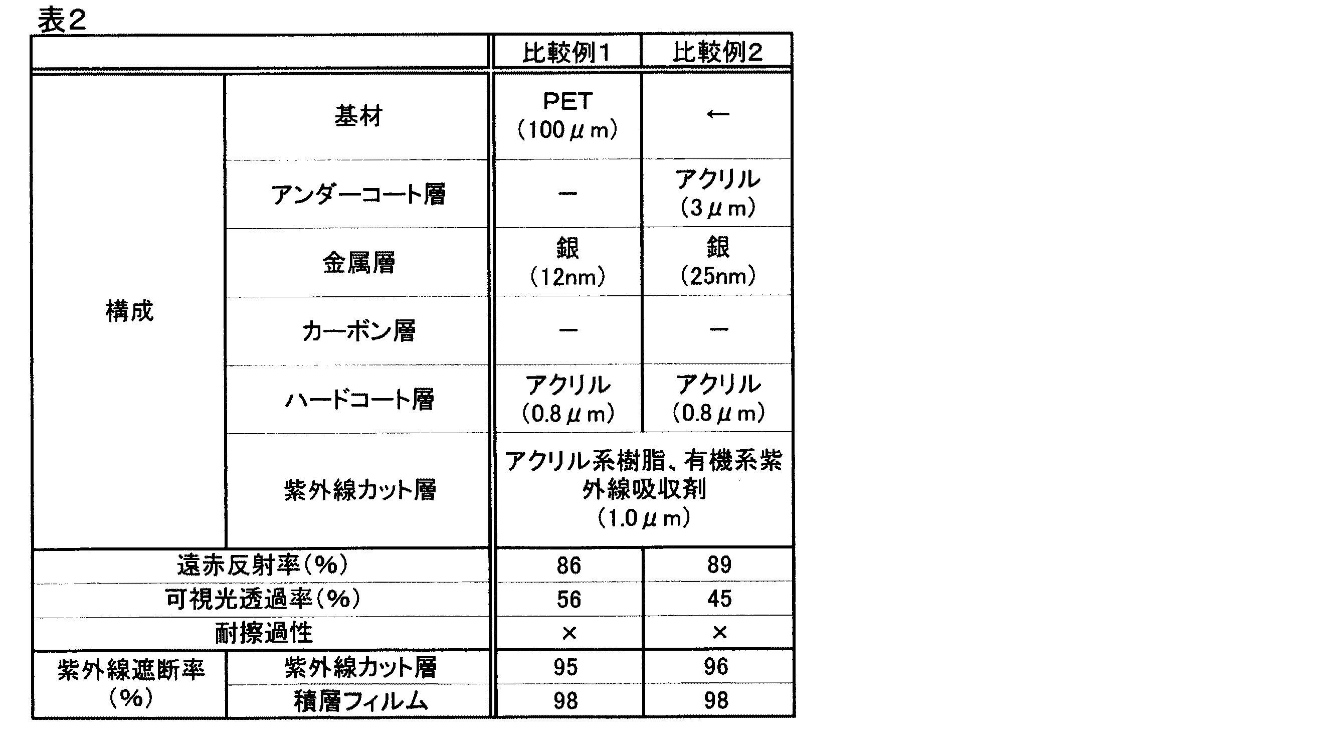
[比較例1]PETフィルム(100μm厚)の片面に実施例1と同様に有機系紫外線吸収剤を混入したアクリル系樹脂層(1μm厚)を形成し、紫外線カット層とした。次に前記PETフィルムの反対面に銀からなる金属層(12nm厚)スパッタリングし、さらに当該銀層上にアクリル系樹脂「オプスターZ7535:JSR(株)製」をコーティング、乾燥した後にUV照射し0.8μm厚のハードコート層を形成させ農業用フィルムを得た。 [Comparative Example 1] An acrylic resin layer (thickness: 1 µm) mixed with an organic ultraviolet absorbent was formed on one side of a PET film (thickness: 100 µm) in the same manner as in Example 1 to obtain an ultraviolet cut layer. Next, a metal layer (12 nm thick) made of silver is sputtered on the opposite surface of the PET film. Further, an acrylic resin “OPSTAR Z7535: manufactured by JSR Corporation” is coated on the silver layer, dried, and then irradiated with UV. An agricultural film was obtained by forming a hard coat layer having a thickness of 8 μm.
[比較例2]PETフィルムと銀層の間にアンダーコート層として、アクリル系樹脂「オプスター(登録商標)Z7535:JSR(株)製」を3μm厚形成したことに加え、ハードコート層の厚みを2.5μmに変更したことを除き、比較例1と同様の方法で試験体を得た。 [Comparative Example 2] In addition to forming an acrylic resin “OPSTAR (registered trademark) Z7535: made by JSR Corporation” as a thickness of 3 μm between the PET film and the silver layer, the thickness of the hard coat layer was A test specimen was obtained in the same manner as in Comparative Example 1 except that the thickness was changed to 2.5 μm.
[比較例3]PETフィルムと銀層の間にアンダーコート層として、アクリル系樹脂「オプスター(登録商標)Z7535:JSR(株)製」を0.8μm厚形成したことに加え、銀層の厚みを25nmに変更したことを除き、比較例1と同様の方法で試験体を得た。 [Comparative Example 3] In addition to forming an acrylic resin “OPSTAR (registered trademark) Z7535: manufactured by JSR Corporation” as a thickness of 0.8 μm as an undercoat layer between the PET film and the silver layer, the thickness of the silver layer A test specimen was obtained in the same manner as in Comparative Example 1 except that was changed to 25 nm.
各試験体の遠赤外線反射率、可視光透過率および耐擦過性の評価結果を表1、表2に示す。 Tables 1 and 2 show the evaluation results of the far-infrared reflectance, visible light transmittance, and scratch resistance of each specimen.
実施例1の紫外線カット層(1μm)/PET(100μm)/金属層(12nm)/カーボン(3nm)/ハードコート層(0.8μm)の構成において、遠赤反射率87%、可視光透過率55%で、耐擦過性は「○」であった。なお、紫外線カット層の紫外線遮断率は97%であり、積層フィルムとしての紫外線遮断率は99%であった。実施例2では、PETと銀層の間にアンダーコート層として、アクリル樹脂(3μm)を積層した。その結果、遠赤反射率85%、可視光透過率56%で、耐擦過性は「◎」となり、アンダーコート層の導入により耐擦過性が向上することを確認した。 In the configuration of the ultraviolet cut layer (1 μm) / PET (100 μm) / metal layer (12 nm) / carbon (3 nm) / hard coat layer (0.8 μm) of Example 1, far-red reflectance 87%, visible light transmittance The scratch resistance was “◯” at 55%. The ultraviolet blocking rate of the ultraviolet blocking layer was 97%, and the ultraviolet blocking rate as a laminated film was 99%. In Example 2, acrylic resin (3 μm) was laminated as an undercoat layer between PET and the silver layer. As a result, the far-red reflectance was 85% and the visible light transmittance was 56%, and the scratch resistance was “◎”. It was confirmed that the scratch resistance was improved by the introduction of the undercoat layer.
なお、紫外線カット層の紫外線遮断率は97%であり、積層フィルムとしての紫外線遮断率は99%であった。実施例3ならびに実施例4では、銀層の厚みをそれぞれ10nm、15nmに変更した。その結果、銀層の厚みに比例し、遠赤反射率が向上し、可視光透過率が低下することが確認できた。なお、紫外線カット層の紫外線遮断率は実施例3で97%、実施例4で97%であり、積層フィルムとしての紫外線遮断率は、実施例3で99%、実施例4で99%であった。実施例5ならびに実施例6では、カーボン層の厚みをそれぞれ1nm、5nmに変更したが、耐擦過性は「○」以上であった。なお、紫外線カット層の紫外線遮断率は実施例5で97%、実施例6で96%であり、積層フィルムとしての紫外線遮断率は、実施例5で99%、実施例6で98%であった。実施例7ならびに実施例8では、ハードコート層のアクリル樹脂の膜厚をそれぞれ0.6μm、1.0μmに変更した。その結果、遠赤反射率はそれぞれ89%、80%、可視光透過率は54%、55%であり、耐擦過性は「○」以上であった。なお、紫外線カット層の紫外線遮断率は実施例7で96%、実施例8で96%であり、積層フィルムとしての紫外線遮断率は、実施例7で98%、実施例8で98%であった。実施例9では、誘電体層としてITO(錫ドープ酸化インジウム)をハードコート層と銀層の間に50nm積層することにより、可視光透過率が65%まで向上することを確認した。なお、紫外線カット層の紫外線遮断率は96%であり、積層フィルムとしての紫外線遮断率は99%であった。
一方、比較例1は、カーボン層が無いことを除き実施例1と同一の構成であるが、耐擦過性評価は「×」であった。なお、紫外線カット層の紫外線遮断率は95%であり、積層フィルムとしての紫外線遮断率は98%であった。
The ultraviolet blocking rate of the ultraviolet blocking layer was 97%, and the ultraviolet blocking rate as a laminated film was 99%. In Example 3 and Example 4, the thickness of the silver layer was changed to 10 nm and 15 nm, respectively. As a result, it was confirmed that the far-red reflectance was increased and the visible light transmittance was decreased in proportion to the thickness of the silver layer. The UV blocking rate of the UV blocking layer was 97% in Example 3 and 97% in Example 4. The UV blocking rate as a laminated film was 99% in Example 3 and 99% in Example 4. It was. In Example 5 and Example 6, the thickness of the carbon layer was changed to 1 nm and 5 nm, respectively, but the scratch resistance was “◯” or more. The UV blocking rate of the UV blocking layer was 97% in Example 5 and 96% in Example 6. The UV blocking rate as a laminated film was 99% in Example 5 and 98% in Example 6. It was. In Example 7 and Example 8, the acrylic resin film thickness of the hard coat layer was changed to 0.6 μm and 1.0 μm, respectively. As a result, the far-red reflectance was 89% and 80%, the visible light transmittance was 54% and 55%, and the scratch resistance was “◯” or more. The UV blocking rate of the UV cut layer was 96% in Example 7 and 96% in Example 8. The UV blocking rate as a laminated film was 98% in Example 7 and 98% in Example 8. It was. In Example 9, it was confirmed that the visible light transmittance was improved to 65% by laminating ITO (tin-doped indium oxide) 50 nm between the hard coat layer and the silver layer as the dielectric layer. The ultraviolet blocking rate of the ultraviolet blocking layer was 96%, and the ultraviolet blocking rate as a laminated film was 99%.
On the other hand, Comparative Example 1 has the same configuration as Example 1 except that there was no carbon layer, but the scuff resistance evaluation was “x”. The ultraviolet blocking rate of the ultraviolet blocking layer was 95%, and the ultraviolet blocking rate as a laminated film was 98%.
その他、比較例2として表2に示したとおりの構成とし、その物性について表2に示す。上述した実施例と比較例とを対比すると、本発明で金属層とハードコート層の間にカーボン層が存在することにより耐擦過性能が向上し、遠赤外線反射性能、紫外線カット性能に優れた多層フィルムが得られる。 In addition, it is set as the structure as shown in Table 2 as the comparative example 2, and it shows in Table 2 about the physical property. In contrast to the above-mentioned Examples and Comparative Examples, the present invention improves the scratch resistance performance due to the presence of the carbon layer between the metal layer and the hard coat layer, and is a multilayer excellent in far-infrared reflection performance and ultraviolet cut performance. A film is obtained.
本発明の多層フィルムは、遠赤外線反射性能、紫外線カット性能および耐擦過性に優れているので、農業用フィルム、例えば温室用に好適である。 Since the multilayer film of the present invention is excellent in far-infrared reflection performance, ultraviolet cut performance and scratch resistance, it is suitable for agricultural films such as greenhouses.
Claims (8)
Priority Applications (1)
| Application Number | Priority Date | Filing Date | Title |
|---|---|---|---|
| JP2011074634A JP2012206430A (en) | 2011-03-30 | 2011-03-30 | Laminated film |
Applications Claiming Priority (1)
| Application Number | Priority Date | Filing Date | Title |
|---|---|---|---|
| JP2011074634A JP2012206430A (en) | 2011-03-30 | 2011-03-30 | Laminated film |
Publications (1)
| Publication Number | Publication Date |
|---|---|
| JP2012206430A true JP2012206430A (en) | 2012-10-25 |
Family
ID=47186617
Family Applications (1)
| Application Number | Title | Priority Date | Filing Date |
|---|---|---|---|
| JP2011074634A Withdrawn JP2012206430A (en) | 2011-03-30 | 2011-03-30 | Laminated film |
Country Status (1)
| Country | Link |
|---|---|
| JP (1) | JP2012206430A (en) |
Cited By (6)
| Publication number | Priority date | Publication date | Assignee | Title |
|---|---|---|---|---|
| JP2015166179A (en) * | 2014-02-12 | 2015-09-24 | ユニチカ株式会社 | Ultraviolet absorbing film |
| JP2017512456A (en) * | 2015-02-23 | 2017-05-25 | イースマート グローバル ライセンシング リミテッド | High density soilless plant growth system and method |
| WO2017150165A1 (en) | 2016-02-29 | 2017-09-08 | 帝人フィルムソリューション株式会社 | Greenhouse, plant cultivation method using said greenhouse, and heat-ray reflecting film structure |
| US10232591B2 (en) | 2014-05-30 | 2019-03-19 | Fujifilm Corporation | Heat insulating window film, heat insulating material for window, and window |
| US11007752B2 (en) | 2018-04-12 | 2021-05-18 | Fujifilm Corporation | Far infrared reflective film, heat shield film, and heat shield glass |
| WO2023074109A1 (en) | 2021-10-25 | 2023-05-04 | 東洋紡株式会社 | Laminate film, film for protected horticulture, and woven/knit fabric |
-
2011
- 2011-03-30 JP JP2011074634A patent/JP2012206430A/en not_active Withdrawn
Cited By (10)
| Publication number | Priority date | Publication date | Assignee | Title |
|---|---|---|---|---|
| JP2015166179A (en) * | 2014-02-12 | 2015-09-24 | ユニチカ株式会社 | Ultraviolet absorbing film |
| US10232591B2 (en) | 2014-05-30 | 2019-03-19 | Fujifilm Corporation | Heat insulating window film, heat insulating material for window, and window |
| JP2017512456A (en) * | 2015-02-23 | 2017-05-25 | イースマート グローバル ライセンシング リミテッド | High density soilless plant growth system and method |
| KR101923285B1 (en) * | 2015-02-23 | 2018-11-28 | 이-스마츠 글로벌 라이센싱 리미티드 | High density soilless plant growth system and method |
| US10327398B2 (en) | 2015-02-23 | 2019-06-25 | E-Smarts Global Licensing Ltd | High density soilless plant growth system and method |
| WO2017150165A1 (en) | 2016-02-29 | 2017-09-08 | 帝人フィルムソリューション株式会社 | Greenhouse, plant cultivation method using said greenhouse, and heat-ray reflecting film structure |
| EP3626048A1 (en) | 2016-02-29 | 2020-03-25 | Teijin Film Solutions Limited | Greenhouse, plant cultivation method using said greenhouse, and heat-ray reflecting film structure |
| US11291167B2 (en) | 2016-02-29 | 2022-04-05 | Toyobo Co., Ltd. | Agricultural greenhouse, plant cultivation method using the same, and heat-ray reflecting film structure |
| US11007752B2 (en) | 2018-04-12 | 2021-05-18 | Fujifilm Corporation | Far infrared reflective film, heat shield film, and heat shield glass |
| WO2023074109A1 (en) | 2021-10-25 | 2023-05-04 | 東洋紡株式会社 | Laminate film, film for protected horticulture, and woven/knit fabric |
Similar Documents
| Publication | Publication Date | Title |
|---|---|---|
| JP5859476B2 (en) | Infrared reflective film | |
| US8753758B2 (en) | Low emissivity and EMI shielding window films | |
| JP6000991B2 (en) | Infrared reflective film | |
| JP2012206430A (en) | Laminated film | |
| WO2012096304A1 (en) | Far infrared reflecting laminate | |
| CN105849597A (en) | Composite film having superior optical and solar performance | |
| KR20170105537A (en) | The multi- | |
| JP6163196B2 (en) | Infrared reflective film | |
| JP2014194535A (en) | Laminated film | |
| JP2014141015A (en) | Laminate film | |
| JP6370347B2 (en) | Infrared reflective film | |
| KR20190131495A (en) | Heat ray permeation inhibiting translucent base unit and translucent base unit | |
| JP2013141753A (en) | Laminated film | |
| JP2001315262A (en) | Antireflection film | |
| JP2016093892A (en) | Laminate | |
| JP6303559B2 (en) | Laminated film and method for producing the same | |
| JP2019008157A (en) | Infrared reflection substrate | |
| KR101239614B1 (en) | Multi-layer thin film for Low emissivity and automobile glass containing the same |
Legal Events
| Date | Code | Title | Description |
|---|---|---|---|
| A300 | Withdrawal of application because of no request for examination |
Free format text: JAPANESE INTERMEDIATE CODE: A300 Effective date: 20140603 |