JP2012205193A - Thermoacoustic device - Google Patents
Thermoacoustic device Download PDFInfo
- Publication number
- JP2012205193A JP2012205193A JP2011069720A JP2011069720A JP2012205193A JP 2012205193 A JP2012205193 A JP 2012205193A JP 2011069720 A JP2011069720 A JP 2011069720A JP 2011069720 A JP2011069720 A JP 2011069720A JP 2012205193 A JP2012205193 A JP 2012205193A
- Authority
- JP
- Japan
- Prior art keywords
- layer
- heating element
- heat
- heat insulating
- insulating layer
- Prior art date
- Legal status (The legal status is an assumption and is not a legal conclusion. Google has not performed a legal analysis and makes no representation as to the accuracy of the status listed.)
- Withdrawn
Links
Images

Classifications
-
- H—ELECTRICITY
- H04—ELECTRIC COMMUNICATION TECHNIQUE
- H04R—LOUDSPEAKERS, MICROPHONES, GRAMOPHONE PICK-UPS OR LIKE ACOUSTIC ELECTROMECHANICAL TRANSDUCERS; ELECTRIC HEARING AIDS; PUBLIC ADDRESS SYSTEMS
- H04R23/00—Transducers other than those covered by groups H04R9/00 - H04R21/00
- H04R23/002—Transducers other than those covered by groups H04R9/00 - H04R21/00 using electrothermic-effect transducer
Landscapes
- Physics & Mathematics (AREA)
- Engineering & Computer Science (AREA)
- Acoustics & Sound (AREA)
- Signal Processing (AREA)
- Electrostatic, Electromagnetic, Magneto- Strictive, And Variable-Resistance Transducers (AREA)
Abstract
Description
本発明は、熱音響装置に関する。 The present invention relates to a thermoacoustic apparatus.
音波を発生させる装置としては、磁石とコイルとを備える動電変換装置、コンデンサ変換装置、圧電材料を用いた変換装置等の機械振動を利用した音波発生装置が広く普及している。近年では、これらの音波発生装置とは異なり、機械振動を全く行わない熱音響効果を利用した音波発生装置(熱音響装置)の開発が進められている。 As a device for generating sound waves, a sound wave generating device using mechanical vibration such as an electrodynamic conversion device including a magnet and a coil, a capacitor conversion device, and a conversion device using a piezoelectric material is widely used. In recent years, unlike these sound wave generators, development of sound wave generators (thermoacoustic devices) using a thermoacoustic effect that does not perform mechanical vibration at all has been underway.
この熱音響装置は、通常、断熱層とこの断熱層表面に設けられた発熱体層とを備える。このような構造を有する熱音響装置においては、電圧を印加すること等により発熱体層が発熱することで発熱体層表面の空気層の温度変化が生じ、この温度変化による空気の疎密により音波が発生するよう構成されている。このような熱音響装置は機械振動を伴わないため、周波数帯域が広い、周囲環境の影響を受けにくい、微細化が比較的容易であるといった利点がある。 This thermoacoustic apparatus usually includes a heat insulating layer and a heating element layer provided on the surface of the heat insulating layer. In a thermoacoustic apparatus having such a structure, the temperature of the air layer on the surface of the heat generating element layer is changed by applying heat to the heat generating element layer, and sound waves are generated due to the air density due to the temperature change. Is configured to occur. Since such a thermoacoustic apparatus does not involve mechanical vibration, there are advantages such as a wide frequency band, being hardly affected by the surrounding environment, and being relatively easy to miniaturize.
従って、この熱音響装置においては、音波の発生効率を高めるため、上記断熱層の断熱性を高めて断熱層側へ発熱体層の熱が流れることを抑え、上述の空気層の温度変化を大きくさせることが重要である。そこで、断熱層が無機ナノ粒子から構成された熱音響装置(特開2009−219089号公報参照)や、断熱層が多数の孔を有するナノ結晶シリコンからなる熱音響装置(特許第3845077号公報参照)が提案されている。 Therefore, in this thermoacoustic device, in order to increase the generation efficiency of sound waves, the heat insulation property of the heat insulation layer is enhanced to suppress the heat of the heating element layer from flowing to the heat insulation layer side, and the temperature change of the air layer is greatly increased. It is important to let Therefore, a thermoacoustic device in which the heat insulating layer is made of inorganic nanoparticles (see JP 2009-219089), or a thermoacoustic device in which the heat insulating layer is made of nanocrystalline silicon having a large number of holes (see Japanese Patent No. 3845077). ) Has been proposed.
しかしながら、上記材料からなる断熱層の表面に、塗布等により発熱体層を積層させると、断熱層内部に発熱体層成分が浸透するため、発熱体層が厚くなる。このように発熱体層が厚くなると、発熱体層の熱容量が大きくなり、電気信号等に対応した高速な温度変化が困難になること等により、熱音響効果による音波の発生能が低下する。さらには、このような熱音響装置においては、断熱層と発熱体層との接触面積が大きくなっているため、断熱性も十分であるとはいえず、この点からも、音波の発生能が高いとは言えない。 However, when the heating element layer is laminated on the surface of the heat insulating layer made of the above material by coating or the like, the heating element layer component penetrates into the heat insulating layer, so that the heating element layer becomes thick. When the heating element layer becomes thick in this way, the heat capacity of the heating element layer increases, and it becomes difficult to change the temperature at a high speed in response to an electrical signal or the like, thereby reducing the ability to generate sound waves due to the thermoacoustic effect. Furthermore, in such a thermoacoustic device, since the contact area between the heat insulating layer and the heating element layer is large, it cannot be said that the heat insulating property is sufficient. It's not expensive.
本発明は、上述のような事情に基づいてなされたものであり、発熱体層の熱容量が小さく、かつ、断熱層の断熱性が高いことで、音波の発生能に優れる熱音響装置を提供することを目的とする。 The present invention has been made based on the above-described circumstances, and provides a thermoacoustic apparatus having excellent sound wave generation capability due to the small heat capacity of the heating element layer and the high heat insulating property of the heat insulating layer. For the purpose.
上記課題を解決するためになされた発明は、
多孔質状の断熱層と、
この断熱層の表面に積層され、線状の炭素素材からなる発熱体層と、
この発熱体層を通電する一対の電極と
を備え、
上記炭素素材の平均長さが、断熱層の表面に現れる孔の平均径より大きい熱音響装置である。
The invention made to solve the above problems is
A porous heat insulating layer;
A heating element layer made of a linear carbon material, laminated on the surface of this heat insulating layer,
A pair of electrodes for energizing the heating element layer,
In the thermoacoustic apparatus, the average length of the carbon material is larger than the average diameter of the holes appearing on the surface of the heat insulating layer.
当該熱音響装置においては、発熱体層が線状の炭素素材から形成されており、この炭素素材の平均長さが断熱層表面に現れる孔の平均径より大きいため、炭素素材が断熱層内部まで入り込みにくい。このため、発熱体層が断熱層の表面に薄膜状に積層され、発熱体層の熱容量が小さくなる。また、この薄膜状の発熱体層が多孔質状の断熱層の表面に積層されるため、発熱体層と断熱層との接触面積が小さく、断熱性に優れる。さらには、発熱体層は、接着剤等を用いず炭素素材のみから構成されていることからも、接着剤の存在による熱容量の上昇及び断熱性の低下が抑えられている。従って、当該熱音響装置は、優れた音波の発生能を有する。 In the thermoacoustic apparatus, the heating element layer is formed of a linear carbon material, and the average length of the carbon material is larger than the average diameter of the holes appearing on the surface of the heat insulating layer. Hard to get in. For this reason, a heat generating body layer is laminated | stacked on the surface of a heat insulation layer in the shape of a thin film, and the heat capacity of a heat generating body layer becomes small. Moreover, since this thin-film heating element layer is laminated on the surface of the porous heat insulating layer, the contact area between the heating element layer and the heat insulating layer is small, and the heat insulating property is excellent. Furthermore, since the heating element layer is made of only a carbon material without using an adhesive or the like, an increase in heat capacity and a decrease in heat insulation due to the presence of the adhesive are suppressed. Therefore, the thermoacoustic apparatus has an excellent ability to generate sound waves.
上記炭素素材がカーボンナノチューブであるとよい。当該熱音響装置によれば、上記炭素素材としてカーボンナノチューブを用いることで、発熱体層の熱容量がより低下し、かつ、表面積が拡大する。従って、当該熱音響装置は、発熱体層の温度変化速度が速く、より優れた音波の発生能を発揮することができる。 The carbon material is preferably a carbon nanotube. According to the thermoacoustic apparatus, by using carbon nanotubes as the carbon material, the heat capacity of the heating element layer is further reduced and the surface area is increased. Therefore, the thermoacoustic apparatus has a high temperature change rate of the heating element layer and can exhibit more excellent sound wave generation ability.
上記炭素素材の少なくとも一部が、断熱層の表面形状に追従して積層されていることが好ましい。当該熱音響装置においては、このように炭素素材の少なくとも一部が断熱層の表面形状に追従して積層されていることで、発熱体層と断熱層との密着性がアンカー効果により高まる。従って、当該熱音響装置によれば、接着剤等を用いず、断熱層表面に発熱体層を固着させることができるため、接着剤等の存在による熱容量の上昇及び断熱性の低下を防ぐことができる。 It is preferable that at least a part of the carbon material is laminated following the surface shape of the heat insulating layer. In the thermoacoustic apparatus, at least a part of the carbon material is laminated following the surface shape of the heat insulating layer in this manner, whereby the adhesion between the heating element layer and the heat insulating layer is enhanced by the anchor effect. Therefore, according to the thermoacoustic apparatus, since the heating element layer can be fixed to the surface of the heat insulating layer without using an adhesive or the like, it is possible to prevent an increase in heat capacity and a decrease in heat insulating property due to the presence of the adhesive or the like. it can.
上記断熱層が、電気絶縁性を有するとよい。当該熱音響装置によれば、電気絶縁性を有する断熱層を用いることで、電流が断熱層側へ流れることが防止される。従って、当該熱音響装置は、発熱体層の発熱効率が高まり、より優れた音波の発生能を発揮することができる。 The said heat insulation layer is good to have electrical insulation. According to the thermoacoustic apparatus, the use of the heat insulating layer having electrical insulation prevents current from flowing to the heat insulating layer side. Therefore, the thermoacoustic device can increase the heat generation efficiency of the heating element layer and can exhibit more excellent sound wave generation ability.
上記断熱層の裏面に積層される放熱層をさらに備えるとよい。当該熱音響装置は、このように放熱層をさらに備えることで、発熱体層の蓄熱が低減される。従って、当該熱音響装置によれば、発熱体層の周辺温度変化の振幅をより大きくすることができ、音波の発生能をさらに高めることができる。 It is good to further provide the heat dissipation layer laminated on the back of the above-mentioned heat insulation layer. The thermoacoustic apparatus further includes the heat dissipation layer as described above, so that the heat storage of the heating element layer is reduced. Therefore, according to the thermoacoustic apparatus, the amplitude of the temperature change around the heating element layer can be further increased, and the sound wave generation capability can be further enhanced.
以上説明したように、本発明の熱音響装置は、発熱体層の熱容量が小さく、かつ、断熱層の断熱性が高いため、音波の発生能に優れる。従って、本発明の熱音響装置は、スピーカー、特に超音波スピーカー等として好適に用いることができる。 As described above, the thermoacoustic device of the present invention is excellent in the ability to generate sound waves because the heat capacity of the heat generating layer is small and the heat insulating property of the heat insulating layer is high. Therefore, the thermoacoustic apparatus of the present invention can be suitably used as a speaker, particularly an ultrasonic speaker.
以下、本発明の熱音響装置の実施の形態を詳説する。 Hereinafter, embodiments of the thermoacoustic apparatus of the present invention will be described in detail.
<第一実施形態>
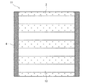
図1の熱音響装置1は、断熱層2、発熱体層3、一対の電極4及び放熱層5を備える。
<First embodiment>
A thermoacoustic device 1 in FIG. 1 includes a
断熱層2は多孔質状である。断熱層2を形成する素材としては、多孔質状であれば特に限定されず、金属素材や非金属素材等を用いることができるが、電気絶縁性を有する素材を用いることが好ましい。当該熱音響装置1において、電気絶縁性を有する断熱層2を用いることで、電流が断熱層2側へ流れることが防止される。従って、当該熱音響装置1は発熱体層3の発熱効率が高まり、優れた音波の発生能を発揮することができる。
The
このような素材としては、例えば、ガラス、ゼオライト、アルミナ、シリカ、セラミックス、その他金属酸化物、エンジニアリングプラスチック、炭素材料(カーボン、炭化ケイ素、炭化チタン等)、窒素材料(窒化ケイ素等)や、表面が酸化物などの絶縁材で被覆されたポーラス金属等を挙げることができる。 Examples of such materials include glass, zeolite, alumina, silica, ceramics, other metal oxides, engineering plastics, carbon materials (carbon, silicon carbide, titanium carbide, etc.), nitrogen materials (silicon nitride, etc.), surface Can be a porous metal coated with an insulating material such as oxide.
上記シリカとしては、例えば、オルトケイ酸テトラメチル(TMOS)、アンモニア水及びエタノールの混合反応から得られる水和ゲルを、超臨界乾燥法を用いて乾燥させることで得られるシリカエアロゲルが好ましい。このシリカエアロゲルは、特に優れた断熱性を発揮することができる。 As the silica, for example, silica aerogel obtained by drying a hydrated gel obtained from a mixed reaction of tetramethyl orthosilicate (TMOS), aqueous ammonia and ethanol using a supercritical drying method is preferable. This silica airgel can exhibit particularly excellent heat insulation.
上記エンジニアリングプラスチックとしては、ポリイミド(PI)、ポリフェニレンスルファイド(PPS)、ポリエーテルイミド(PEI)、ポリエーテルエーテルケトン(PEEK)、フッ素樹脂等の耐熱温度が150℃以上、好ましくは200℃以上の樹脂が好ましい。 As the engineering plastic, the heat resistance temperature of polyimide (PI), polyphenylene sulfide (PPS), polyetherimide (PEI), polyetheretherketone (PEEK), fluororesin, etc. is 150 ° C. or higher, preferably 200 ° C. or higher. Resins are preferred.
断熱層2を形成する素材の25℃下の熱伝導率としては、0.1W/mK以下が好ましく、0.06W/mK以下がさらに好ましく、0.03W/mK以下が特に好ましい。なお、熱伝導率は、JIS−R1611(2010)に記載のフラッシュ法により測定することができる。
The thermal conductivity at 25 ° C. of the material forming the
断熱層2の空隙率の下限としては、50体積%が好ましく、80体積%がより好ましく、90体積%がさらに好ましい。断熱層2がこのような空隙率を有することで、断熱性能を効果的に発揮することができる。なお、断熱層2の空隙率の上限は、強度の低下を抑えるため、99体積%が好ましく、97体積%がより好ましい。なお、空隙率は、アルキメデス法により算出することができる。
As a minimum of the porosity of
断熱層2表面に現れる孔の平均径(R)の下限としては、5nmが好ましく、10nmがさらに好ましい。一方、この平均径(R)の上限としては、1,000nmが好ましく、200nmがさらに好ましい。表面に存在する孔の平均径(R)を上記範囲とすることで、発熱体層2を形成する線状の炭素素材が、断熱層2の内部まで入り込むことを防ぐことができる。
The lower limit of the average diameter (R) of the holes appearing on the surface of the
なお、この表面に現れる孔の平均径は、表面の孔が明確に確認できる倍率で走査型電子顕微鏡(SEM)等を用いて写真を撮り、任意の30個の孔の等価円直径を測定し数平均することで求めることができる。等価円直径は、楕円形状である場合、短径をa、長径をbとすると、(a×b)0.5で求めることができる。 The average diameter of the holes appearing on the surface was measured with a scanning electron microscope (SEM) or the like at a magnification at which the surface holes could be clearly confirmed, and the equivalent circular diameter of any 30 holes was measured. It can be obtained by number averaging. In the case of an elliptical shape, the equivalent circular diameter can be obtained by (a × b) 0.5 , where a is the minor axis and b is the major axis.
また、断熱層2全体の孔の平均径の下限としては、5nmが好ましく、10nmがさらに好ましい。一方、断熱層2全体の孔の平均径の上限としては、1,000nmが好ましく、200nmがさらに好ましい。全体の孔の平均径が5nm未満の場合は、十分な断熱性が発揮されない場合がある。逆に、全体の孔の平均径が1,000nmを超える場合は強度が低下するおそれがある。
Moreover, as a minimum of the average diameter of the hole of the
なお、断熱層2のサイズ及び平面形状としては特に限定されず、用途等に応じて適宜設定することができるが、例えば一辺の長さが50mm〜200mm程度の矩形形状とすることができる。このようなサイズの断熱層2を備える熱音響装置は、小型の超音波スピーカー等として好適に用いることができる。
In addition, it does not specifically limit as a size and planar shape of the
また、断熱層2の平均厚さとしては、例えば0.1mm以上3mm以下とすることができる。断熱層2の平均厚さが上記下限未満の場合は、断熱性及び強度が低下するおそれがある。逆に、断熱層2の平均厚さが上記上限を超える場合は、断熱層2の放熱性が低下するおそれがある。
Moreover, as average thickness of the
発熱体層3は、断熱層2の表面の略全面に積層されている。また、発熱体層3は、複数の線状の炭素素材6からなる。
The
線状の炭素素材6の平均長さ(L)は、断熱層2の表面に現れる孔の平均径(R)より大きい。このため炭素素材6は、その柔軟性のため、断熱層2の表面形状に追従するが、断熱層2の内部まで入り込みにくい。従って、発熱体層3は断熱層2の表面に薄膜状に積層され、発熱体層3の熱容量が小さくなる。また、この薄膜状の発熱体層3が多孔質状の断熱層2の表面に積層されるため、発熱体層3と断熱層2との接触面積が小さく、断熱性に優れる。さらには、発熱体層3は、接着剤等を用いず炭素素材6のみから構成されていることからも、接着剤の存在による熱容量の上昇及び断熱性の低下が抑えられている。従って、当該熱音響装置1は、優れた音波の発生能を発揮することができる。
The average length (L) of the
炭素素材6は、断熱層2の表面全面にランダム、かつ略均一に配置されている。なお、各炭素素材6は部分的に重なりあっていることで、発熱体層3として導電性を有している。炭素素材6をこのようにランダムにかつ略均一に配置することで、発熱体層3が放熱しやすい形状となっている。
The
炭素素材6の平均長さ(L)は、断熱層2の表面に現れる孔の平均径(R)より大きいが、この平均長さ(L)は孔の平均径(R)の2倍以上であることが好ましく、5倍以上であることがさらに好ましい。なお、孔の平均径(R)に対するこの平均長さ(L)の上限としては特に制限されないが、例えば1,000倍程度である。炭素素材6の具体的平均長さ(L)としては、例えば0.01mm以上10mm以下程度であり、0.1mm以上5mm以下が好ましいる。
The average length (L) of the
炭素素材6の直径としては、断熱層2の表面に現れる孔の平均径(R)より小さいことが好ましい。この場合、炭素素材6の少なくとも一部が、断熱層2の表面に現れる孔に浸入することができ、アンカー効果により、発熱体層3の固着性を高めることができる。炭素素材6の直径としては、具体的には、1.5nm以上100nm以下が好ましい。
The diameter of the
この炭素素材6の具体的材質としては、線状である限り特に限定されず、例えば炭素繊維、カーボンナノチューブ(CNT)等を挙げることができるが、特にCNTが好ましい。炭素素材6としてCNTを用いることで、発熱体層3の熱容量がより低下し、かつ、表面積が拡大する。従って、当該熱音響装置1は、発熱体層3の温度変化速度が速く、より優れた音波の発生能を発揮することができる。
The specific material of the
上記CNTとしては、単層のシングルウォールナノチューブ(SWNT)や、多層のマルチウォールナノチューブ(MWNT)のいずれも用いることができる。但し、SWNTは導体と半導体が混在するものが多く、導電性の点から、MWNTが好ましく、直径1.5nm以上100nm以下のMWNTがさらに好ましい。 As the CNT, either single-wall single-wall nanotubes (SWNT) or multi-wall multi-wall nanotubes (MWNT) can be used. However, many SWNTs include a mixture of a conductor and a semiconductor, and from the viewpoint of conductivity, MWNT is preferable, and MWNT having a diameter of 1.5 nm to 100 nm is more preferable.
なお、CNTは個々の分子が独立した、紡がれていない状態のものを用いるとよい。このようなCNTを用いることで、発熱体層3の均一性が高まると共に、表面積が拡がるため、発熱体層3の温度変化速度が速く、音波の発生能をより高めることができる。
In addition, as for CNT, it is good to use the thing in which each molecule | numerator became independent and was not spun. By using such CNTs, the uniformity of the
上記CNTは、公知の方法で製造することができ、例えば、CVD法、アーク法、レーザーアブレーション法、DIPS法、CoMoCAT法等により製造することができる。これらの中でも、MWNTであり、かつ所望するサイズのCNTを効率的に得ることができる点から、鉄やニッケルなどの金属触媒とし、エチレンガスを用いたCVD法により製造することが好ましい。 The CNT can be produced by a known method, for example, by a CVD method, an arc method, a laser ablation method, a DIPS method, a CoMoCAT method, or the like. Among these, since it is MWNT and a CNT having a desired size can be efficiently obtained, it is preferable to use a metal catalyst such as iron or nickel, and to manufacture by a CVD method using ethylene gas.
上記炭素素材6の少なくとも一部が、断熱層2の表面形状に追従して積層されていることが好ましい。具体的には、図1(a)の炭素素材6aのように、炭素素材6の少なくとも一部、が断熱層2表面の孔内に潜り込んだ状態で固着されていることが好ましい。当該熱音響装置1においては、このように炭素素材6の少なくとも一部が断熱層2の表面形状に追従して積層されていることで、発熱体層3と断熱層2との密着性がアンカー効果により高まる。従って、当該熱音響装置1によれば、接着剤等を用いず、断熱層2表面に発熱体層3を固着させることができるため、接着剤等の存在による熱容量の上昇及び断熱性の低下を防ぐことができる。
It is preferable that at least a part of the
上記発熱体層3の平均厚さとしては、50nm以上1,000nm以下が好ましく、100nm以上500nm以下がさらに好ましい。発熱体層3の平均厚さが上記下限未満の場合は、著しく抵抗が上昇し、発熱しにくくなる場合がある。逆に、この平均厚さが上記上限を超える場合は、発熱体層3内部で熱が蓄積し、音波に変換されにくくなる。
The average thickness of the
上記発熱体層3のインピーダンスの下限としては、1Ωが好ましく、5Ωがさらに好ましい。一方、このインピーダンスの上限としては1,000Ωが好ましく、100Ωがさらに好ましい。発熱体層3のインピーダンスが上記下限未満の場合は、電流が流れやすく発火して燃えてしまうおそれがある。一方、このインピーダンスが上記上限を超えると、電流が流れにくくなり発熱しにくく発音せず、電流を流そうとする場合には高電圧が必要となる。
The lower limit of the impedance of the
一対の電極4は、発熱体層3の表面の、対向する二辺上にそれぞれ帯状に設けられている。この電極4の材質としては、導電性を有する限り特に限定されず、例えば銀粒子を含有する導電性接着剤等を用いることができる。一対の電極4は、発熱体層3を通電し、発熱させる。
The pair of
放熱層5は、断熱層2の裏面に積層されている。当該熱音響装置1は、このように放熱層5をさらに備えることで、発熱体層3の蓄熱が低減される。従って、当該熱音響装置1によれば、発熱体層3の温度変化をより大きくすることができ、音波の発生能をさらに高めることができる。
The
この放熱層5の材質としては特に限定されず、例えば金属、金属酸化物、金属窒化物、これらの粉末が混合された樹脂材料等が挙げられるが、銅、アルミニウム等の熱伝導率が高い金属が好ましい。放熱層5の厚さとしては、特に限定されず、例えば100nm以上1mm以下程度である。なお、表面積を広げ、放熱性を高めるために、放熱層5の裏面(断熱層2と接しない側の面)に凹凸形状等が形成されていてもよい。
The material of the
当該熱音響装置1においては、一対の電極4に交流の信号電圧を印加することで、発熱体層3が発熱する。この発熱により、発熱体層3の表面の空気層の温度変化が生じ、この温度変化による空気の疎密により音波が発生する。当該熱音響装置1は、上述の構成を有するため、発熱体層3の熱容量が小さく、かつ、断熱層2の断熱性が高い。従って、当該熱音響装置1によれば、発熱体層3の温度変化、及びこれに伴うこの表面の空気層の温度変化が大きく、音波の発生能に優れる。従って、当該熱音響装置1は発生する音波の音圧が大きく、スピーカー、特に超音波スピーカー等として好適に用いることができる。
In the thermoacoustic apparatus 1, the
(製造方法)
当該熱音響装置1は、例えば以下の方法で好適に製造することができる。
(Production method)
The thermoacoustic apparatus 1 can be suitably manufactured by the following method, for example.
まず、線状の炭素素材6を溶媒に分散させた分散液を調製する。この溶媒としては、特に限定されないが、例えば水に界面活性剤(例えばドデシルベンゼンスルホン酸ナトリウム,SDBS)を添加したものやイソプロピルアルコール等のアルコール類、N−メチル−2−ピロリドン(N−methylpyrrolidone, NMP)などの極性溶媒を用いることができる。
First, a dispersion in which the
この分散液を断熱層2の表面に塗布する。この塗布の方法としては特に限定されず、例えばスピンコートや、スプレー塗布により行うことができる。
This dispersion is applied to the surface of the
塗布後、加熱により乾燥させることにより、炭素素材からなる発熱体層3を形成する。この加熱の際の温度としては、溶媒の沸点等により調整されるが、例えば100〜500℃である。なお、断熱層2がエンジニアリングプラスチックなど、軟化点が比較的低いものである場合は、断熱層2の変形を防止するため、軟化点以下の加熱温度とすることが好ましい。
After application, the
形成された発熱体層3の両端辺に、導電性接着剤の塗布等により電極4を形成する。断熱層2の裏面に放熱層5を貼り合わせることで、熱音響装置1を得ることができる。放熱層5の貼り合わせは、発熱体層3の積層前でも後でもよい。
なお、上記とは異なる製造方法としては、断熱層の表面に、線状の炭素素材からなる発熱体薄膜(例えば、線状の炭素素材からなる不織布等)を単に積層させることで発熱体層を形成する方法も挙げられる。なお、発熱体薄膜の積層後、発熱体薄膜の表面を加圧したり、擦り合わせたりすることにより、発熱体層の少なくとも一部が、断熱層の表面形状に追従した状態を形成することができる。 In addition, as a manufacturing method different from the above, the heating element layer is formed by simply laminating a heating element thin film made of a linear carbon material (for example, a nonwoven fabric made of a linear carbon material) on the surface of the heat insulating layer. The method of forming is also mentioned. In addition, after laminating the heating element thin film, it is possible to form a state in which at least a part of the heating element layer follows the surface shape of the heat insulating layer by pressurizing or rubbing the surface of the heating element thin film. .
<第二実施形態>
図2の熱音響装置11は、断熱層2、発熱体層13、一対の電極4及び放熱層(図示しない)を備える。発熱体層13以外は、図1の熱音響装置1で説明したものと同様なので、説明を省略する。
<Second embodiment>
The
発熱体層13は、線状の炭素素材6からなり、断熱層2の表面に積層されている。発熱体層13は、一対の電極4の対向方向を長手方向とするストライプ状に積層されている。発熱体層13をこのようにストライプ状に形成することで、発熱体層13の表面積を広げることができる。従って、熱音響装置11は、発熱体層13に熱が溜まることがさらに低減され、音波の発生能が高い。
The
このストライプ状の各発熱体層13の幅及び間隔としては、特に限定されず、例えば、0.01mm以上2mm以下程度である。
The width and interval of each stripe-shaped
このようなストライプ状の発熱体層13は、例えば、スクライブ塗布や、ストライプ状にマスキングした上に上述した分散液を塗布すること、あるいはスクリーン印刷等により形成することができる。
Such a stripe-shaped
<その他の実施形態>
本発明の熱音響装置は、上記実施形態に限定されるものではない。例えば、放熱層は無くても可能であり、本発明の熱音響装置を構成することができる。また、線状の炭素素材をランダムな配置ではなく、一対の電極の対向方向に配置させることもできる。さらには、線状の炭素素材としてCNTを用いた場合、各CNT分子を一対の電極の対向方向に、かつ、各CNT分子の両端がいずれかの電極上に位置するように配置することもできる。このようにCNT分子を配置させた発熱体層によれば、分子間力によるCNT間の接続点がないため、この接続点から生じる熱容量の上昇を抑えることができる。
<Other embodiments>
The thermoacoustic apparatus of the present invention is not limited to the above embodiment. For example, it is possible without the heat dissipation layer, and the thermoacoustic device of the present invention can be configured. Further, the linear carbon material can be arranged in the opposing direction of the pair of electrodes instead of being randomly arranged. Furthermore, when CNT is used as the linear carbon material, each CNT molecule can be arranged in the facing direction of the pair of electrodes, and both ends of each CNT molecule are positioned on one of the electrodes. . According to the heating element layer in which the CNT molecules are arranged in this manner, there is no connection point between CNTs due to intermolecular force, and thus an increase in heat capacity generated from this connection point can be suppressed.
以下、実施例によって本発明をさらに詳細に説明するが、本発明はこれらの実施例に限定されるものではない。 EXAMPLES Hereinafter, although an Example demonstrates this invention further in detail, this invention is not limited to these Examples.
[実施例1]
断熱層として、縦及び横60mm、厚さ0.5mmの多孔質状シリカ板を用意した。この断熱層の表面に現れる孔の平均径は36nmであり、空隙率は95体積%であった。
[Example 1]
As the heat insulating layer, a porous silica plate having a length and width of 60 mm and a thickness of 0.5 mm was prepared. The average diameter of the holes appearing on the surface of the heat insulating layer was 36 nm, and the porosity was 95% by volume.
線状の炭素素材として、平均長さ1.4mm、平均径25nmのMWNTを用いた。このMWNTを水に界面活性剤SDBSを1質量%添加した溶液に分散させて分散液を調整した。この分散液を断熱層の表面に塗布し、乾燥させて、発熱体層を形成した。この発熱体層の両端辺に銀粒子を含む導電性接着剤を積層し、幅2mmの一対の電極を形成し、実施例1の熱音響装置を得た。 As the linear carbon material, MWNT having an average length of 1.4 mm and an average diameter of 25 nm was used. This MWNT was dispersed in a solution obtained by adding 1% by mass of a surfactant SDBS to water to prepare a dispersion. This dispersion was applied to the surface of the heat insulating layer and dried to form a heating element layer. A conductive adhesive containing silver particles was laminated on both ends of the heating element layer to form a pair of electrodes having a width of 2 mm, and the thermoacoustic device of Example 1 was obtained.
発熱体層の厚みをSEMにより測定したところ、約100nmであった。また、電極間の抵抗を測定したところ、約15Ωであった。 When the thickness of the heating element layer was measured by SEM, it was about 100 nm. Moreover, when the resistance between electrodes was measured, it was about 15Ω.
[実施例2]
分散液の塗布量を変えたこと以外は、実施例1と同様の操作をして、発熱体層の厚みが5,000nmである実施例2の熱音響装置を得た。電極間の抵抗を測定したところ、0.7Ωであった。
[Example 2]
A thermoacoustic device of Example 2 in which the thickness of the heating element layer was 5,000 nm was obtained by performing the same operation as in Example 1 except that the coating amount of the dispersion liquid was changed. The resistance between the electrodes was measured and found to be 0.7Ω.
[評価]
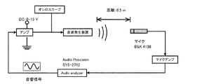
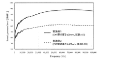
図3の装置を組み、周波数特性の評価を行った。入力信号は、Vdc=10V、Vp−p=10Vとした。また、周波数は、100Hz〜100kHzの範囲のサイン波を用い、サンプリング周波数は192kHzとした。得られた結果を図4に示す。
[Evaluation]
The apparatus of FIG. 3 was assembled and the frequency characteristics were evaluated. The input signals were Vdc = 10V and Vp−p = 10V. The frequency was a sine wave in the range of 100 Hz to 100 kHz, and the sampling frequency was 192 kHz. The obtained results are shown in FIG.
実施例1及び実施例2の熱音響装置も十分な音圧の音波を発生することができる。特に、発熱体層が薄い実施例1の熱音響装置は、発生する音波の音圧が大きく、音波発生能に優れていることがわかる。 The thermoacoustic apparatus of Example 1 and Example 2 can also generate a sound wave with sufficient sound pressure. In particular, it can be seen that the thermoacoustic device of Example 1 having a thin heating element layer has a large sound pressure of the generated sound wave and is excellent in sound wave generation ability.
本発明の熱音響装置は、スピーカー、特に超音波スピーカー等として好適に利用することができる。 The thermoacoustic apparatus of the present invention can be suitably used as a speaker, particularly an ultrasonic speaker.
1、11 熱音響装置
2 断熱層
3、13 発熱体層
4 電極
5 放熱層
6、6a 炭素素材
DESCRIPTION OF
Claims (5)
この断熱層の表面に積層され、線状の炭素素材からなる発熱体層と、
この発熱体層を通電する一対の電極と
を備え、
上記炭素素材の平均長さが、断熱層の表面に現れる孔の平均径より大きい熱音響装置。 A porous heat insulating layer;
A heating element layer made of a linear carbon material, laminated on the surface of this heat insulating layer,
A pair of electrodes for energizing the heating element layer,
The thermoacoustic apparatus in which the average length of the carbon material is larger than the average diameter of the holes appearing on the surface of the heat insulating layer.
The thermoacoustic apparatus of any one of Claims 1-4 further provided with the thermal radiation layer laminated | stacked on the back surface of the said heat insulation layer.
Priority Applications (1)
| Application Number | Priority Date | Filing Date | Title |
|---|---|---|---|
| JP2011069720A JP2012205193A (en) | 2011-03-28 | 2011-03-28 | Thermoacoustic device |
Applications Claiming Priority (1)
| Application Number | Priority Date | Filing Date | Title |
|---|---|---|---|
| JP2011069720A JP2012205193A (en) | 2011-03-28 | 2011-03-28 | Thermoacoustic device |
Publications (1)
| Publication Number | Publication Date |
|---|---|
| JP2012205193A true JP2012205193A (en) | 2012-10-22 |
Family
ID=47185668
Family Applications (1)
| Application Number | Title | Priority Date | Filing Date |
|---|---|---|---|
| JP2011069720A Withdrawn JP2012205193A (en) | 2011-03-28 | 2011-03-28 | Thermoacoustic device |
Country Status (1)
| Country | Link |
|---|---|
| JP (1) | JP2012205193A (en) |
Cited By (3)
| Publication number | Priority date | Publication date | Assignee | Title |
|---|---|---|---|---|
| WO2018026267A1 (en) | 2016-08-01 | 2018-02-08 | Technische Universiteit Delft | Three dimensional thermoacoustic device composed of na- noporous material and the method to fabricate such a device |
| JP2018133625A (en) * | 2017-02-13 | 2018-08-23 | ヤマハファインテック株式会社 | Thermoacoustic device and acoustic wave inspection device |
| WO2021213577A1 (en) * | 2020-04-21 | 2021-10-28 | Christian-Albrechts-Universität Zu Kiel | Method for activating a gas, electrothermal gas actuator, and use of a gas actuator |
-
2011
- 2011-03-28 JP JP2011069720A patent/JP2012205193A/en not_active Withdrawn
Cited By (5)
| Publication number | Priority date | Publication date | Assignee | Title |
|---|---|---|---|---|
| WO2018026267A1 (en) | 2016-08-01 | 2018-02-08 | Technische Universiteit Delft | Three dimensional thermoacoustic device composed of na- noporous material and the method to fabricate such a device |
| NL2017268B1 (en) * | 2016-08-01 | 2018-02-09 | Univ Delft Tech | Three dimensional thermoacoustic device composed of nanoporous material and the method to fabricate such a device |
| JP2018133625A (en) * | 2017-02-13 | 2018-08-23 | ヤマハファインテック株式会社 | Thermoacoustic device and acoustic wave inspection device |
| WO2021213577A1 (en) * | 2020-04-21 | 2021-10-28 | Christian-Albrechts-Universität Zu Kiel | Method for activating a gas, electrothermal gas actuator, and use of a gas actuator |
| US12143773B2 (en) | 2020-04-21 | 2024-11-12 | Christian-Albrechts-Universitaet Zu Kiel | Method for activating a gas, electrothermal gas actuator, and use of a gas actuator |
Similar Documents
| Publication | Publication Date | Title |
|---|---|---|
| JP2012205198A (en) | Thermoacoustic device | |
| US9635468B2 (en) | Encapsulated thermoacoustic projector based on freestanding carbon nanotube film | |
| CN101990152B (en) | Thermal sounding device and manufacturing method thereof | |
| JP2011050051A (en) | Thermoacoustic device with heat dissipating structure | |
| JP5134129B2 (en) | Thermoacoustic device | |
| CN102056064B (en) | Loudspeaker | |
| CN101715160B (en) | Flexible sound producing device and sound producing flag | |
| TWI429296B (en) | speaker | |
| CN102724613A (en) | A thermal sounding device and an electronic device | |
| JP5139408B2 (en) | Thermoacoustic device | |
| JP2012205193A (en) | Thermoacoustic device | |
| US8452031B2 (en) | Ultrasonic thermoacoustic device | |
| JP5818852B2 (en) | Thermoacoustic device | |
| CN101783996B (en) | Thermoacoustic device | |
| CN102724617B (en) | Thermoacoustic device and electronic device | |
| US20110215673A1 (en) | Ultrasonic wave generator | |
| CN103841481B (en) | Earphone | |
| JP2009296592A (en) | Thermoacoustic device | |
| JP5134128B2 (en) | Thermoacoustic device | |
| CN102724614B (en) | A thermal sounding device and an electronic device | |
| TWI351681B (en) | Acoustic device | |
| JP5134126B2 (en) | Thermoacoustic device | |
| JP5134127B2 (en) | Thermoacoustic device | |
| Baughman et al. | Encapsulated thermoacoustic projector based on freestanding carbon nanotube film | |
| TWI383691B (en) | Flexible sounding device |
Legal Events
| Date | Code | Title | Description |
|---|---|---|---|
| A300 | Withdrawal of application because of no request for examination |
Free format text: JAPANESE INTERMEDIATE CODE: A300 Effective date: 20140603 |