JP2012203340A - Lens device - Google Patents
Lens device Download PDFInfo
- Publication number
- JP2012203340A JP2012203340A JP2011070296A JP2011070296A JP2012203340A JP 2012203340 A JP2012203340 A JP 2012203340A JP 2011070296 A JP2011070296 A JP 2011070296A JP 2011070296 A JP2011070296 A JP 2011070296A JP 2012203340 A JP2012203340 A JP 2012203340A
- Authority
- JP
- Japan
- Prior art keywords
- ring member
- ring
- slide position
- focus ring
- magnet
- Prior art date
- Legal status (The legal status is an assumption and is not a legal conclusion. Google has not performed a legal analysis and makes no representation as to the accuracy of the status listed.)
- Granted
Links
Images


Landscapes
- Focusing (AREA)
- Lens Barrels (AREA)
Abstract
Description
本発明はレンズ装置に係り、特にレンズ装置のリング部材のクリック機構に関する。 The present invention relates to a lens device, and more particularly to a click mechanism for a ring member of the lens device.
従来、テレビの取材等で使用される持ち運び可能なENG(Electronic News Gathering)カメラに用いられるレンズ装置において、フォーカスリングを手動で回動操作することによりフォーカスレンズを移動させて焦点調節を行うマニュアルフォーカス(MF)時に、フォーカスリングの回動位置に応じた絶対位置信号をフォーカスレンズの移動指令として出力する第1のMFモードと、フォーカスリングの回転量に応じた相対位置信号をフォーカスレンズの移動指令として出力する第2のMFモードとを有するものが知られている(特許文献1)。 Conventionally, in a lens device used in a portable ENG (Electronic News Gathering) camera used for TV coverage, etc., manual focus is performed by moving the focus lens by manually rotating the focus ring. At the time of (MF), a first MF mode for outputting an absolute position signal corresponding to the rotation position of the focus ring as a focus lens movement command, and a relative position signal corresponding to the rotation amount of the focus ring as a focus lens movement command And a second MF mode that is output as (Patent Document 1).
図11は特許文献1に記載のレンズ装置の要部の拡大断面図である。
FIG. 11 is an enlarged cross-sectional view of a main part of the lens device described in
このレンズ装置は、レンズ鏡胴本体の一部を構成する前固定環1の外周部に、第1フォーカスリング2、及び第2フォーカスリング3がそれぞれ回動可能に配置され、第1フォーカスリング2は、回動範囲が規制されておらず、エンドレス回転させることができるとともに、光軸方向にスライド可能に配設され、第2フォーカスリング3は、ストッパーにより約120度の範囲内で回動できるように規制されている。尚、エンドレス回転とは、回転の始点や終点が無く、360度以上回転運動可能な構成を指す。
In this lens apparatus, a
第1フォーカスリング2と第2フォーカスリング3とが対向する端面には、それぞれ鋸歯状のクラッチ部2A、3Aが形成されており、図12に示す状態では、クラッチ部2A,3Aが連結(噛合)し、第1フォーカスリング2と第2フォーカスリング3とが一体的に回動する。従って、この状態で、第1フォーカスリング2を手動で回動させる場合には、約120度の範囲内でのみ回動させることができる。
Sawtooth-
一方、第1フォーカスリング2を、クリック用弾性部材4を乗り越えるように前方にスライドさせると、前記クラッチ部2A、3Aの連結が外れる。これにより第1フォーカスリング70は、エンドレス回転できるようになる。
On the other hand, when the
クリック用弾性部材4は、図13に示すように前固定環1の周囲を3等分割した各位置に配設され、その中央部の上面にかまぼこ形状を有する凸部4Aが形成されている。第1フォーカスリング2の内周面のうちのほぼ中央部の内周面には、2つの斜面を有する断面三角形状の当接部2Bが形成されている。この第1フォーカスリング2をスライド操作し、第1フォーカスリング2の当接部2Bが、クリック用弾性部材4の凸部4Aを押し下げて乗り越える、図11に示す位置に移動すると、第1フォーカスリング2の端部に形成されたクラッチ部2Aが、第2フォーカスリング72の端部に形成されたクラッチ部3Aと噛み合い、第1フォーカスリング70と第2フォーカスリング72とが一体的に回動できるようになる。
As shown in FIG. 13, the click
一方、第1フォーカスリング2を、図11上で左方向にスライド操作し、第1フォーカスリング2の当接部2Bが、クリック用弾性部材4の凸部4Aを押し下げて乗り越える所定の位置に移動すると、クラッチ部2A、3Aの連結が外れる。これにより、第1フォーカスリング2はエンドレス回転が可能になる。
On the other hand, the
そして、第1フォーカスリング2をスライド操作し、第1フォーカスリング2の当接部2Bが、クリック用弾性部材4の凸部4Aを乗り越えて移動するときにクリック力が生じ、クリック感が得られる。
Then, when the
また、クリック感を操作者に付与するために、マグネットを使用した操作モード選択装置が提案されている(特許文献2)。 Also, an operation mode selection device using a magnet has been proposed in order to give a click feeling to an operator (Patent Document 2).
この操作モード選択装置は、操作ダイヤルにN極とS極とを交互に同一円周上に設けたクリック感用可動マグネットを配置し、このクリック感用可動マグネットと対向する位置に、同一ピッチで異なる磁極を交互に同一円周上に設けたクリック感用固定マグネットを配置して構成され、前記クリック感用固定マグネットとの間の吸引力、反発力によって生じるクリック感を操作ダイヤルに付与するようにしている。 In this operation mode selection device, a click feeling movable magnet having N poles and S poles alternately arranged on the same circumference is arranged on the operation dial, and at the same pitch at a position facing the click feeling movable magnet. A click feeling fixed magnet having different magnetic poles alternately arranged on the same circumference is arranged, and a click feeling generated by an attractive force and a repulsive force with the click feeling fixed magnet is imparted to the operation dial. I have to.
特許文献1に記載のレンズ装置のクリック機構は、第1フォーカスリング2のスライド位置が切り替わるときの感触(「カチッ」というクリック感)が弱いという問題がある。また、第1フォーカスリング2がクリック用弾性部材4を乗り越えた際に、クリック用弾性部材4により付与される両端側への引き込み力が弱いという問題がある。尚、クリック用弾性部材4の弾性力を強くすることにより上記の問題を解決することが考えられるが、この場合には、クリック用弾性部材4を乗り越えるための第1フォーカスリング2の操作力が過大となり、操作しにくくなるという問題がある。
The click mechanism of the lens device described in
一方、特許文献2に記載の操作モード選択装置は、操作ダイヤルを所定の角度ずつ回動させる毎に、クリック感用固定マグネットとクリック感用可動マグネットとの相互の吸引力及び反発力とによりクリック感が得られるが、このクリック感は、操作ダイヤルを回動させる際に生じる操作ダイヤルの負荷の変化であり、操作ダイヤルの移動後に「カチッ」という感触が指先に返ってくるものではない。
On the other hand, every time the operation dial is rotated by a predetermined angle, the operation mode selection device described in
本発明はこのような事情に鑑みてなされたもので、レンズ鏡胴本体に対して回転するとともに光軸方向にスライド移動するリング部材のスライド移動による切替え時の感触を向上させることができるレンズ装置を提供することを目的とする。 The present invention has been made in view of such circumstances, and a lens device capable of improving the touch at the time of switching by sliding movement of a ring member that rotates relative to the lens barrel body and slides in the optical axis direction. The purpose is to provide.
前記目的を達成するために本発明の一の態様に係るレンズ装置は、レンズ鏡胴本体に対してエンドレス回転が可能に配設されるとともに、光軸方向の第1のスライド位置と第2のスライド位置との間でスライド自在に配設された第1のリング部材と、前記レンズ鏡胴本体に対して所定の回動範囲内のみで回動自在に配設された第2のリング部材であって、前記第1のリング部材が前記第1のスライド位置に移動すると、該第1のリング部材の一方の側面と当接可能に配設された第2のリング部材と、前記レンズ鏡胴本体に対してエンドレス回転が可能に配設された第3のリング部材であって、前記第1のリング部材が前記第2のスライド位置に移動すると、該第1のリング部材の他方の側面と当接可能に配設された第3のリング部材と、前記第1のリング部材のスライド方向の両端面に設けられた第1の磁性部材と、前記第2のリング部材及び第3のリング部材の前記第1のリング部材の端面に対向する面に設けられた第2の磁性部材と、を備え、前記第1、第2の磁性部材の少なくとも一方は磁石により構成され、前記第1のリング部材は、該第1のリング部材の第1のスライド位置への移動時又は第2のスライド位置への移動時に磁力により前記第2のリング部材又は第3のリング部材と吸着されることにより、第2のリング部材又は第3のリング部材と連動して回転するように構成されたことを特徴としている。 In order to achieve the above object, a lens apparatus according to one aspect of the present invention is disposed so as to be capable of endless rotation with respect to a lens barrel body, and has a first slide position and a second slide in the optical axis direction. A first ring member that is slidably arranged between the slide position and a second ring member that is arranged to be rotatable only within a predetermined rotation range with respect to the lens barrel body. When the first ring member moves to the first slide position, a second ring member disposed so as to be in contact with one side surface of the first ring member, and the lens barrel A third ring member arranged to be endlessly rotatable with respect to the main body, and when the first ring member moves to the second slide position, the other side surface of the first ring member; A third ring member disposed so as to be capable of contacting; A first magnetic member provided on both end surfaces in the sliding direction of the first ring member, and a surface of the second ring member and a third ring member facing the end surface of the first ring member. A second magnetic member, wherein at least one of the first and second magnetic members is constituted by a magnet, and the first ring member is moved to a first slide position of the first ring member. When it is moved or moved to the second slide position, it is attracted to the second ring member or the third ring member by a magnetic force and rotates in conjunction with the second ring member or the third ring member. It is characterized by having been comprised.
本発明の一の態様に係るレンズ装置によれば、第1のリング部材を第1のスライド位置に移動させると、第1のリング部材の一方の端面に設けられた第1の磁性部材と、前記第2のリング部材の前記第1のリング部材の一方の端面に対向する面に設けられた第2の磁性部材とが当接し、前記第1、第2の磁性部材の少なくとも一方の磁石による磁力により吸着させることができ、同様に第1のリング部材を第2のスライド位置に移動させると、第1のリング部材の他方の端面に設けられた第1の磁性部材と、前記第3のリング部材の前記第1のリング部材の他方の端面に対向する面に設けられた第2の磁性部材とが当接し、前記第1、第2の磁性部材の少なくとも一方の磁石による磁力により吸着させることができる。上記磁力による第1、第2のリング部材間の当接時、又は第1、第3のリング部材間の当接時に良好な切替え感触(「カチッ」という指先に返ってくる感触)を得ることができる。また、前記第1のリング部材と第2のリング部材とは磁力により吸着するため、第1のリング部材を操作することにより第2のリング部材を所定の回動範囲内で回動させることができ、前記第1、第2の磁性部材は、第1のリング部材から第2のリング部材に回動力を伝達し、又は切断するためのクラッチ部として機能することができる。 According to the lens device of one aspect of the present invention, when the first ring member is moved to the first slide position, the first magnetic member provided on one end surface of the first ring member; A second magnetic member provided on a surface of the second ring member facing one end surface of the first ring member is in contact with at least one of the first and second magnetic members. Similarly, when the first ring member is moved to the second slide position, the first magnetic member provided on the other end surface of the first ring member, and the third magnetic member can be adsorbed by magnetic force. A second magnetic member provided on a surface of the ring member facing the other end surface of the first ring member abuts and is attracted by a magnetic force generated by at least one magnet of the first and second magnetic members. be able to. When the first and second ring members are in contact with each other by the magnetic force, or when the first and third ring members are in contact, a good switching feel (feeling of “clicking back”) is obtained. Can do. Further, since the first ring member and the second ring member are attracted by a magnetic force, the second ring member can be rotated within a predetermined rotation range by operating the first ring member. In addition, the first and second magnetic members can function as a clutch unit for transmitting a turning force from the first ring member to the second ring member or for cutting.
本発明の他の態様に係るレンズ装置は、レンズ鏡胴本体に対してエンドレス回転が可能に配設されるとともに、光軸方向の第1のスライド位置と第2のスライド位置との間でスライド自在に配設された第1のリング部材と、前記レンズ鏡胴本体に対して所定の回動範囲内のみで回動自在に配設された第2のリング部材であって、前記第1のリング部材が前記第1のスライド位置に移動すると、該第1のリング部材の一方の側面と当接可能に配設された第2のリング部材と、前記レンズ鏡胴本体に対してエンドレス回転が可能に配設された第3のリング部材であって、前記第1のリング部材が前記第2のスライド位置に移動すると、該第1のリング部材の他方の側面と当接可能に配設された第3のリング部材と、前記レンズ鏡胴本体の外周面に設けられた第1の磁石と前記第1のリング部材の内周面に設けられた第2の磁石とからなる一対の第1及び第2の磁石であって、前記第1のリング部材が前記第1のスライド位置と第2のスライド位置との中間位置に位置するときに、互いに反発するようにそれぞれS極、N極が設けられ、前記第1のリング部材が前記中間位置からずれると、該第1のリング部材を前記第2のリング部材の端面又は第3のリング部材の端面に押圧するように磁力により付勢する第1及び第2の磁石と、を備えたことを特徴としている。 The lens device according to another aspect of the present invention is disposed so as to be capable of endless rotation with respect to the lens barrel body, and slides between a first slide position and a second slide position in the optical axis direction. A first ring member arranged freely, and a second ring member arranged rotatably with respect to the lens barrel body only within a predetermined rotation range, When the ring member moves to the first slide position, endless rotation is performed with respect to the second ring member disposed so as to be in contact with one side surface of the first ring member and the lens barrel body. A third ring member arranged to be able to come into contact with the other side surface of the first ring member when the first ring member moves to the second slide position. A third ring member and an outer peripheral surface of the lens barrel body. A pair of first and second magnets, each of which includes a first magnet and a second magnet provided on an inner peripheral surface of the first ring member, wherein the first ring member is When it is located at an intermediate position between the first slide position and the second slide position, an S pole and an N pole are provided so as to repel each other, and when the first ring member is displaced from the intermediate position, And a first magnet and a second magnet biased by a magnetic force so as to press the first ring member against an end surface of the second ring member or an end surface of the third ring member. .
本発明の他の態様に係るレンズ装置によれば、前記レンズ鏡胴本体の外周面に設けられた第1の磁石と前記リング部材の内周面に設けられた第2の磁石とからなる一対の第1及び第2の磁石は、前記第1のリング部材が前記第1のスライド位置と第2のスライド位置の中間に位置するときに、互いに反発するようにそれぞれS極、N極が設けられ、前記第1のリング部材が前記中間位置からずれると、該第1のリング部材を前記第2のリング部材の端面又は第3のリング部材の端面に押圧するように磁力により付勢することができる。前記第1のリング部材をスライドさせる際に、第1のリング部材が中間位置に近づくにつれて大きな操作力を必要とし、中間位置を越えると、第1のリング部材は、第1、第2の磁石の磁力により他方のスライド位置に移動させられ、第2又は第3のリング部材に当接するとともに、磁力により付勢される。この第1のリング部材の当接時に良好な切替え感触を得ることができ、また、第1のリング部材のスライド位置が中間位置の前後で第1のリング部材の操作力が変化し、クリック感を得ることができる。 According to the lens device according to another aspect of the present invention, a pair of the first magnet provided on the outer peripheral surface of the lens barrel body and the second magnet provided on the inner peripheral surface of the ring member. The first and second magnets are respectively provided with an S pole and an N pole so as to repel each other when the first ring member is positioned between the first slide position and the second slide position. When the first ring member is displaced from the intermediate position, the first ring member is biased by a magnetic force so as to press the end surface of the second ring member or the end surface of the third ring member. Can do. When the first ring member is slid, a large operating force is required as the first ring member approaches the intermediate position. When the first ring member is exceeded, the first ring member becomes the first and second magnets. It is moved to the other slide position by the magnetic force of, and abuts against the second or third ring member and is urged by the magnetic force. A good switching feeling can be obtained when the first ring member abuts, and the operating force of the first ring member changes before and after the slide position of the first ring member is in the middle position, and a click feeling is obtained. Can be obtained.
本発明の更に他の態様に係るレンズ装置は、レンズ鏡胴本体に対してエンドレス回転が可能に配設されるとともに、光軸方向の第1のスライド位置と第2のスライド位置との間でスライド自在に配設された第1のリング部材と、前記レンズ鏡胴本体に対して所定の回動範囲内のみで回動自在に配設された第2のリング部材であって、前記第1のリング部材が前記第1のスライド位置に移動すると、該第1のリング部材の一方の側面と当接可能に配設された第2のリング部材と、前記レンズ鏡胴本体に対してエンドレス回転が可能に配設された第3のリング部材であって、前記第1のリング部材が前記第2のスライド位置に移動すると、該第1のリング部材の他方の側面と当接可能に配設された第3のリング部材と、前記レンズ鏡胴本体の外周面に設けられた第1の磁石と前記第1のリング部材の内周面に設けられた第2の磁石とからなる一対の第1及び第2の磁石であって、前記第1のリング部材が前記第1のスライド位置と第2のスライド位置との中間位置に位置するときに、互いに反発するようにそれぞれS極、N極が設けられ、前記第1のリング部材が前記中間位置からずれると、該第1のリング部材を前記第2のリング部材の端面又は第3のリング部材の端面に押圧するように磁力により付勢する第1及び第2の磁石と、前記第1のリング部材のスライド方向の両端面に設けられた第1の磁性部材と、前記第2のリング部材及び第3のリング部材の前記第1のリング部材の端面に対向する面に設けられた第2の磁性部材と、を備え、前記第1、第2の磁性部材の少なくとも一方は磁石により構成され、前記第1のリング部材は、該第1のリング部材の第1のスライド位置への移動時又は第2のスライド位置への移動時に磁力により前記第2のリング部材又は第3のリング部材と吸着されることを特徴としている。 The lens device according to still another aspect of the present invention is disposed so as to be capable of endless rotation with respect to the lens barrel body, and between the first slide position and the second slide position in the optical axis direction. A first ring member that is slidably disposed, and a second ring member that is pivotally disposed within a predetermined rotation range with respect to the lens barrel body, wherein When the ring member moves to the first slide position, the second ring member disposed so as to come into contact with one side surface of the first ring member and endless rotation with respect to the lens barrel body The third ring member is disposed so as to be capable of contacting the other side surface of the first ring member when the first ring member moves to the second slide position. Third ring member and the outer periphery of the lens barrel body A pair of first and second magnets, each of which includes a first magnet provided on the inner peripheral surface of the first ring member and a second magnet provided on an inner peripheral surface of the first ring member. When an S pole and an N pole are provided so as to repel each other when positioned at an intermediate position between the first slide position and the second slide position, the first ring member is displaced from the intermediate position. The first and second magnets biased by magnetic force so as to press the first ring member against the end surface of the second ring member or the end surface of the third ring member; and A first magnetic member provided on both end surfaces in the sliding direction, and a second magnetic member provided on a surface of the second ring member and a third ring member facing the end surface of the first ring member. And at least one of the first and second magnetic members The first ring member is formed by a magnetic force when the first ring member is moved to the first slide position or to the second slide position. It is characterized by being adsorbed to the third ring member.
本発明の更に他の態様に係るレンズ装置によれば、前記第1、第2の磁性部材の少なくとも一方の磁石による磁力と、前記第1、第2の磁石による磁力との両者により、第1、第2のリング部材間の当接時、又は第1、第3のリング部材間の当接時に良好な切替え感触を得ることができる。 According to the lens device in accordance with still another aspect of the present invention, the first and second magnetic members can generate the first by both the magnetic force of at least one of the magnets and the magnetic force of the first and second magnets. A good switching feeling can be obtained at the time of contact between the second ring members or at the time of contact between the first and third ring members.
本発明の更に他の態様に係るレンズ装置において、前記第1の磁性部材及び第2の磁性部材の少なくとも一方は、リング状に形成されていることを特徴としている。これにより、前記第1のリング部材の回転位置にかかわらず、前記第1、第2の磁性部材の間で吸着力が得られるようになっている。 In the lens device according to still another aspect of the present invention, at least one of the first magnetic member and the second magnetic member is formed in a ring shape. Accordingly, an attractive force can be obtained between the first and second magnetic members regardless of the rotational position of the first ring member.
本発明の更に他の態様に係るレンズ装置において、前記第1の磁石及び第2の磁石の少なくとも一方は、リング状に形成されていることを特徴としている。これにより、前記第1のリング部材の回転位置にかかわらず、前記第1、第2の磁石の間で磁力が得られるようにしている。 In the lens device according to still another aspect of the present invention, at least one of the first magnet and the second magnet is formed in a ring shape. Accordingly, a magnetic force is obtained between the first and second magnets regardless of the rotational position of the first ring member.
本発明の更に他の態様に係るレンズ装置において、前記第1のリング部材の前記第1のスライド位置への移動時に前記第2のリング部材の回動位置に応じた絶対位置信号をフォーカスレンズの移動指令として出力する第1のマニュアルフォーカスモードと、前記第1のリング部材の前記第2のスライド位置への移動時に前記第1のリング部材又は第3のリング部材の回転量に応じた相対位置信号をフォーカスレンズの移動指令として出力する第2のマニュアルフォーカスモードとを切り替えるフォーカスモード切替え手段を備えたことを特徴としている。これにより、前記第1のリング部材を前記第1のスライド位置に移動させると、第1のマニュアルフォーカスモードに切り替えられ、前記第1のリング部材により回動可能な第2のリング部材の回動位置に応じた絶対位置信号をフォーカスレンズの移動指令として出力することができ、また、前記第1のリング部材を前記第2のスライド位置に移動させると、第2のマニュアルフォーカスモードに切り替えられ、前記第1のリング部材の回動量、又は第1のリング部材により回動可能な第3のリング部材の回転量に応じた相対位置信号をフォーカスレンズの移動指令として出力することができる。 In the lens device according to still another aspect of the present invention, an absolute position signal corresponding to the rotational position of the second ring member is transmitted to the focus lens when the first ring member is moved to the first slide position. A first manual focus mode that is output as a movement command, and a relative position according to the amount of rotation of the first ring member or the third ring member when the first ring member moves to the second slide position A focus mode switching means for switching between a second manual focus mode for outputting a signal as a focus lens movement command is provided. As a result, when the first ring member is moved to the first slide position, the first ring member is switched to the first manual focus mode, and the second ring member is rotatable by the first ring member. An absolute position signal corresponding to the position can be output as a focus lens movement command, and when the first ring member is moved to the second slide position, it is switched to the second manual focus mode, A relative position signal corresponding to the amount of rotation of the first ring member or the amount of rotation of the third ring member that can be rotated by the first ring member can be output as a focus lens movement command.
本発明の更に他の態様に係るレンズ装置において、前記第1のリング部材の光軸方向の第1のスライド位置又は第2のスライド位置への移動に伴って、前記第1のリング部材と第2のリング部材とを機械的に連結又は非連結させるクラッチ部を設けたことを特徴としている。これにより、前記第1のリング部材と第2のリング部材とが当接すると、前記第1のリング部材と第2のリング部材とが機械的に連結されるため、前記第1のリング部材の回動力を前記第2のリング部材に確実に伝達することができる。
In the lens device according to still another aspect of the present invention, the first ring member and the first ring member are moved in accordance with the movement of the first ring member to the first slide position or the second slide position in the optical axis direction. A clutch portion for mechanically connecting or disconnecting the
本発明によれば、レンズ鏡胴本体に対して回転するとともに光軸方向にスライド移動するリング部材のスライド移動時に、その移動端において磁石により他のリング部材に吸着させ、又は付勢させて当接させるようにしたため、リング部材間の当接時に良好な切替え感触を得ることができる。 According to the present invention, when the ring member that rotates relative to the lens barrel body and slides in the optical axis direction slides, the ring member is attracted to or biased by another ring member at the moving end. Since they are in contact with each other, a good switching feeling can be obtained when the ring members are in contact with each other.
以下、添付図面に従って本発明に係るレンズ装置の実施の形態について説明する。 Hereinafter, embodiments of a lens apparatus according to the present invention will be described with reference to the accompanying drawings.
本発明に係るレンズ装置は、例えば民生用のビデオカメラ、テレビ放送用のENGカメラ、監視用カメラ等に適用されるレンズ装置である。 The lens device according to the present invention is a lens device applied to, for example, consumer video cameras, ENG cameras for television broadcasting, surveillance cameras, and the like.
光学系の焦点位置を変更するフォーカスレンズは、光軸方向に移動可能に配設され、ボイスコイルモータ(VCM)等の動力によって電動で光軸方向に駆動されるようになっている。 A focus lens that changes the focal position of the optical system is disposed so as to be movable in the optical axis direction, and is electrically driven in the optical axis direction by power such as a voice coil motor (VCM).
レンズ装置には、AF/MF切替えスイッチ、ノンロック式のAFプッシュスイッチ等の操作スイッチが設けられており、これらのスイッチの操作によりフォーカスレンズを制御できるようになっている。 The lens device is provided with operation switches such as an AF / MF switching switch and a non-locking AF push switch, and the focus lens can be controlled by operating these switches.
AF/MF切替えスイッチは、被写体像のコントラストが最大になるように自動的にフォーカスレンズを移動させて焦点調節を行うオートフォーカス(AF)モードと、後述する第1フォーカスリング20を手動で回転操作することによりフォーカスレンズを移動させて焦点調節を行うマニュアルフォーカス(MF)モードとを切り替えるスイッチである。AFプッシュスイッチは、AF/MF切替えスイッチによりMFモードに切り替えられている場合に、キートップが押下(プッシュ)されている期間だけAFモードに切り替えるスイッチである。
The AF / MF selector switch manually rotates the autofocus (AF) mode in which the focus lens is automatically moved to adjust the focus so that the contrast of the subject image is maximized, and the
[第1の実施形態]
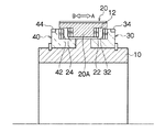
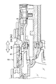
図1は本発明に係るレンズ装置の第1の実施形態を示す要部断面図であり、第1フォーカスリング20がスライド方向の中間位置に位置している状態に関して示している。
[First Embodiment]
FIG. 1 is a cross-sectional view of a main part showing a first embodiment of a lens apparatus according to the present invention, and shows a state in which a
図1において、レンズ装置のレンズ鏡胴本体10は、非磁性体であるアルミ合金により形成されており、このレンズ鏡胴本体10には、それぞれポリカーボネート等の樹脂からなる第1フォーカスリング20、第2フォーカスリング30及び第3フォーカスリング40がそれぞれ回動可能に配置されている。
In FIG. 1, a lens barrel
第1フォーカスリング20は、回転範囲が規制されておらず、エンドレス回転が可能に配設されるとともに、光軸方向(矢印A,B方向)にスライド可能に配設されている。また、第2フォーカスリング30は、図示しないストッパーにより約120度の範囲内で回動できるように規制され、第3フォーカスリング40は、回転範囲が規制されておらず、エンドレス回転が可能に配設されている。
The
前記レンズ鏡胴本体10の外周面の一部、前記第2フォーカスリング30及び第3フォーカスリング40により、所定幅を有する周状の凹溝12が形成され、第1フォーカスリング20の下面側には、前記凹溝12と係合する凸部20Aが形成されている。
A circumferential
上記第1フォーカスリング20の凸部20Aの両側面には、それぞれ磁石22、24が配設され、これらの磁石22、24に対向する第2フォーカスリング30、及び第3フォーカスリング40の側面には、それぞれ磁石32、42が配設されている。
ここで、前記磁石22と磁石32、及び磁石24と磁石42の各一対の磁石は、互いに吸着力が作用するように(N極とS極とが対向するように)磁極の方向が決定されて配置されている。また、前記磁石22と磁石32、及び磁石24と磁石42の各一対の磁石のうちの少なくとも一方は、リング状に形成されており、これにより、第1フォーカスリング20の回転位置にかかわらず、上記磁石間で吸着力が得られるようになっている。
Here, the directions of the magnetic poles of the pair of
更に、第2フォーカスリング30及び第3フォーカスリング40の周囲には、それぞれ歯車34,44が形成されており、これらの歯車34,44は、それぞれ図示しない絶対位置検出型センサ(アブソリュートエンコーダ)、及び相対位置検出型センサ(インクリメンタルエンコーダ)の検出軸の歯車に連結している。
Further, gears 34 and 44 are formed around the
上記絶対位置検出型センサにより第2フォーカスリング30の絶対的な回転位置を検知することができるとともに、相対位置検出型センサにより第3フォーカスリング40の相対的な回転量を検知することができるようになっている。
The absolute rotation position of the
次に、上記構成の第1の実施形態のレンズ装置の作用について説明する。 Next, the operation of the lens apparatus according to the first embodiment having the above-described configuration will be described.
図1は、第1フォーカスリング20がスライド方向(矢印AB方向)の中間位置に位置している状態に関して示している。この状態では、磁石22と磁石32との間隔、及び磁石24と磁石42との間隔が同じため、同じ磁力で互いに吸引して釣り合っているが、この状態は不安定な状態であるため、通常、この中間位置で第1フォーカスリング20が停止することはない。
FIG. 1 shows a state in which the
図2及び図3は、それぞれ本発明に係るレンズ装置の第1の実施形態を示す要部断面図であり、第1フォーカスリング20がスライド方向(矢印A方向)の一端の第1のスライド位置に位置している状態、及び第1フォーカスリング20がスライド方向(矢印B方向)の他端の第2のスライド位置に位置している状態に関して示している。
2 and 3 are cross-sectional views showing the main part of the lens device according to the first embodiment of the present invention. The
図2に示すように、第1フォーカスリング20が手動により矢印A方向にスライド操作され、図1に示した中間位置を越えると、第1フォーカスリング20は、磁石22と磁石32との間に生じる磁力により吸引されて矢印A方向の移動端(第1のスライド位置)まで移動する。
As shown in FIG. 2, when the
第1フォーカスリング20の矢印A方向の移動端では、第1フォーカスリング20側の磁石22が第2フォーカスリング30側の磁石34に当接し、磁石22と磁石34とが吸着固定される。上記磁石22、32間の吸着力による当接時に、第1フォーカスリング20に触れている指先には、「カチッ」という感触が伝わり、良好な切替え感触が得られる。
At the moving end of the
ここで、第1フォーカスリング20を回転させると、第1フォーカスリング20に磁力により吸着している第2フォーカスリング30が同時に回転する。第2フォーカスリング30は、前述したように回動範囲が約120°に制限されているため、第1フォーカスリング20は、この制限された回動範囲内で回動可能になる。
Here, when the
一方、図2に示す状態から第1フォーカスリング20を、磁石22と磁石32との吸着力に抗して矢印B方向にスライド操作し、第1フォーカスリング20が、図1に示した中間位置を越えると、図3に示すように、磁石24と磁石42との間に生じる磁力により吸引されて矢印A方向の移動端(第2のスライド位置)まで移動する。
On the other hand, the
第1フォーカスリング20の矢印B方向の移動端では、第1フォーカスリング20側の磁石24が第3フォーカスリング40側の磁石42に当接し、磁石24と磁石42とが吸着固定される。上記磁石24、42間の吸着力による当接時に、第1フォーカスリング20に触れている指先には、「カチッ」という感触が伝わり、良好な切替え感触が得られる。
At the moving end of the
ここで、第1フォーカスリング20を回転させると、第1フォーカスリング20に磁力により吸着している第3フォーカスリング40が同時に回転する。第3フォーカスリング40は、前述したように回転範囲が規制されておらず、エンドレス(エンド端なし)で回転可能に配設されているため、第1フォーカスリング20は、第3フォーカスリング40とともにエンドレスで回転させることができる。
Here, when the
ところで、前述したようにAF/MF切替えスイッチによりMFモードに切り替えられると、第1フォーカスリング20の手動操作によるフォーカスレンズの移動制御が可能になる。また、MFモードに切り替えられている場合には、第1フォーカスリング20のスライド位置に応じて、フルMFモード(エンド端付き)とAF/MFモード(エンド端なし)との切替えが行われる。
By the way, as described above, when the mode is switched to the MF mode by the AF / MF switching switch, the movement control of the focus lens by the manual operation of the
第1フォーカスリング20のスライド位置(図2に示した第1のスライド位置、及び図3に示した第2のスライド位置)は、第1フォーカスリング20のスライド位置に応じてON/OFFする、フォトインタラプタやマイクロスイッチ等の検出手段(図示せず)の検出信号により検知することができる。そして、フォーカスモード切替え手段は、前記検出手段により第1フォーカスリング20が図2に示した第1のスライド位置にあることが検知されると、フルMFモード(エンド端付き)に切り替え、第1フォーカスリング20が図3に示した第2のスライド位置にあることが検知されると、AF/MFモード(エンド端なし)に切り替える。
The slide position of the first focus ring 20 (the first slide position shown in FIG. 2 and the second slide position shown in FIG. 3) is turned ON / OFF according to the slide position of the
図2に示したように第1フォーカスリング20と第2フォーカスリング30とが磁石22、32により連結され、MFモードとしてフルMFモード(エンド端付き)に切り替えられると、第2フォーカスリング30の歯車34に連結している絶対位置検出型センサからの絶対位置信号(至近から無限遠の範囲内の撮影距離を指令する信号)に基づいてフォーカスレンズが駆動制御される。このようにフルMFモードに切り替えられると、第1フォーカスリング20を手動で操作することにより、フォーカスレンズを所望の撮影距離に対応する位置に移動させることができる。尚、第1フォーカスリング20は、ストッパーによって回動範囲が規制されている端付きの第2フォーカスリング30に連結しているため、その回動範囲が第2フォーカスリング30と同様に規制され、至近端から無限遠端に対応する回動範囲内で回動できるようになっている。
As shown in FIG. 2, when the
上記フルMFモードは、第1フォーカスリング20が第2フォーカスリング30を介して回動範囲が制限されており、操作者は、第1フォーカスリング20がエンド端に到達したときの操作感によってフォーカスレンズが至近端又は無限遠端に到達したことを認識することができる。このような第1フォーカスリング20のみによるフォーカス操作は、本職のカメラマン等が使い慣れた方式である。
In the full MF mode, the rotation range of the
一方、図3に示したように第1フォーカスリング20と第3フォーカスリング40とが磁石24、42により連結され、MFモードとしてAF/MFモード(エンド端なし)に切り替えられると、第1フォーカスリング20を回転させることによりフォーカスレンズを移動させるMFモードと、前述したAFプッシュスイッチの押下によるAFモードとを適宜使い分けてフォーカス制御を行うことができる。
On the other hand, as shown in FIG. 3, when the
即ち、AF/MFモード時に第1フォーカスリング20が操作されると、第1フォーカスリング20とともに回転する第3フォーカスリング40の歯車44に連結している相対位置検出型センサからの相対位置信号に基づいて、第1フォーカスリング20の回動量に対応した移動量だけフォーカスレンズを移動させることができる。
That is, when the
尚、AF/MFモード時にAFプッシュスイッチの押下によりAFモードに一時的に切り替え、その後、AFプッシュスイッチから手を離してMFモードに切り替えると、AFモードによって自動的に合焦したフォーカスレンズの位置を引き継いで、第1フォーカスリング20を操作した分だけフォーカスレンズを変位させることができ、使い勝手がよくなる。
When the AF push switch is pressed during AF / MF mode, the AF lens is temporarily switched to AF mode. After that, when the AF push switch is released and switched to MF mode, the position of the focus lens automatically focused by the AF mode is changed. As a result, the focus lens can be displaced by the amount of operation of the
また、第1の実施形態では、一対の磁石22と磁石32、及び磁石24と磁石42を使用しているが、一対の磁石のうちの一方は、磁石の替わりに鉄等の軟磁性材料からなる磁性部材としてもよい。
In the first embodiment, the pair of
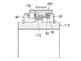
[第2の実施形態]
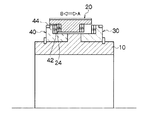
図4は本発明に係るレンズ装置の第2の実施形態を示す要部断面図であり、第1フォーカスリング120がスライド方向の中間位置に位置している状態に関して示している。
[Second Embodiment]
FIG. 4 is a cross-sectional view of an essential part showing a second embodiment of the lens apparatus according to the present invention, and shows a state in which the
上述した第1の実施形態のレンズ装置は、第1フォーカスリング20、第2フォーカスリング30及び第3フォーカスリング40のリング間に互いに吸引する磁石を設けるようにしたが、第2の実施形態のレンズ装置は、主として、図4に示すようにレンズ鏡胴本体110と、第1フォーカスリング120との間に、互いに反発する磁石112、磁石122を設けるようにした点で、第1の実施形態と相違する。
In the lens apparatus of the first embodiment described above, the magnets that attract each other are provided between the rings of the
尚、レンズ鏡胴本体110に取り付けられた第1フォーカスリング120、第2フォーカスリング130、及び第3フォーカスリング140の構造等は、第1の実施形態の第1フォーカスリング20、第2フォーカスリング30、及び第3フォーカスリング40とほぼ同様になっている。
The structure of the
レンズ鏡胴本体110の外周面(第2フォーカスリング130と第3フォーカスリング140との間の外周面)には、磁石112が設けられている。
A
一方、第1フォーカスリング120の内周面(前記磁石112と対向する位置)には、磁石122が配設されている。
On the other hand, a
図4に示すように第1フォーカスリング120は、スライド方向(矢印AB方向)の中間位置に位置しており、この状態では、レンズ鏡胴本体110側の磁石112と第1フォーカスリング120側の磁石122とは、互いに反発するように同じ極性の磁極が対向している。また、磁石112と磁石122のうちの少なくとも一方は、リング状に形成されており、これにより、第1フォーカスリング120の回転位置にかかわらず、上記磁石間で反発力等の磁力が得られるようになっている。
As shown in FIG. 4, the
また、第2の実施形態では、第1フォーカスリング120の両端面には、鋸歯状の機械的なクラッチ部124、126が形成されており、第2フォーカスリング130及び第3フォーカスリング140の内側の端面には、前記クラッチ部124、126と噛み合う鋸歯状のクラッチ部132、142が形成されている。
In the second embodiment, serrated mechanical
次に、上記構成の第2の実施形態のレンズ装置の作用について説明する。 Next, the operation of the lens apparatus according to the second embodiment having the above-described configuration will be described.
図4は、前述したように第1フォーカスリング20がスライド方向(矢印AB方向)の中間位置に位置している状態に関して示している。この状態では、磁石112と磁石122とが、レンズ鏡胴本体110の径方向に反発し、第1フォーカスリング120のスライド方向(矢印AB方向)への反発力は発生していない。尚、第1の実施形態と同様に、この状態は不安定な状態であるため、通常、この中間位置で第1フォーカスリング20が停止することはない。
FIG. 4 shows a state in which the
図5及び図6は、それぞれ本発明に係るレンズ装置の第2の実施形態を示す要部断面図であり、第1フォーカスリング120がスライド方向(矢印A方向)の一端の第1のスライド位置に位置している状態、及び第1フォーカスリング120がスライド方向(矢印B方向)の他端の第2のスライド位置に位置している状態に関して示している。
FIG. 5 and FIG. 6 are cross-sectional views showing the main part of a second embodiment of the lens apparatus according to the present invention, respectively, where the
図5に示すように、第1フォーカスリング120が手動により矢印A方向にスライド操作され、図4に示した中間位置を越えると、第1フォーカスリング120は、磁石112と磁石122との反発力により矢印A方向の移動端まで移動する。
As shown in FIG. 5, when the
第1フォーカスリング120の矢印A方向の移動端では、第1フォーカスリング120側のクラッチ部124が第2フォーカスリング130側のクラッチ部132に当接し、クラッチ部124、132が噛み合う。尚、クラッチ部124、132が噛み合っている状態では、第1フォーカスリング120は、図5に示すように磁石112、122の磁力により第2フォーカスリング130側に付勢される。
At the moving end of the
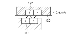
図7は図5の要部拡大図である。図7に示すように磁石112と磁石122との間では、同じ極性の磁極同士により反発力が発生し、異極の磁極同士により吸着力が発生し、これらの磁力により第1フォーカスリング120には、第2フォーカスリング130と当接する付勢力が加わる。
FIG. 7 is an enlarged view of a main part of FIG. As shown in FIG. 7, between the
上記磁石112、122による付勢力による当接時に、第1フォーカスリング120を介して良好な切替え感触が得られる。
A good switching feeling can be obtained via the
ここで、第1フォーカスリング120を回転させると、第1フォーカスリング120が磁力により付勢され、クラッチ部124、132により機械的に連結された第2フォーカスリング130を同時に回転させることができ、これにより第2フォーカスリング130の回動位置に応じた絶対位置信号を出力することができる。
Here, when the
尚、第1フォーカスリング120は、クラッチ部124、132により第2フォーカスリング130と機械的に連結されるため、第2フォーカスリング130がエンド端に達したときには、第1フォーカスリング120を確実に停止させることができる。これにより、第1フォーカスリング120がエンド端に到達したときの操作感が得られる。
Since the
一方、図5に示す状態から第1フォーカスリング120を、磁石112、122による付勢力に抗して矢印B方向にスライド操作し、第1フォーカスリング120が、図4に示した中間位置を越えると、図6に示すように、第1フォーカスリング120は、磁石112、122の磁力(図5の場合とは逆方向の磁力)により矢印B方向の移動端まで移動する。
On the other hand, the
また、第1フォーカスリング120をスライドさせる際に、第1フォーカスリング120が中間位置に近づくにつれて大きな操作力を必要とし、中間位置を越えると、急激に操作力が不要となるとともに、第1フォーカスリング120は、磁石112、122の磁力により矢印B方向の移動端まで移動する。この第1フォーカスリング120の操作力の変化により、良好な切替え感触が得られる。
Further, when the
第1フォーカスリング120の矢印B方向の移動端では、第1フォーカスリング120側のクラッチ部126が第3フォーカスリング140側のクラッチ部142に当接し、クラッチ部126、142が噛み合う。尚、クラッチ部126、142が噛み合っている状態では、第1フォーカスリング120は、図6に示すように磁石112、122の磁力により第3フォーカスリング140側に付勢され、クラッチ部126、142を介して第3フォーカスリング140と機械的に連結される。
At the moving end of the
ここで、第1フォーカスリング120を回転させると、第1フォーカスリング120に磁力により付勢され、クラッチ部126、142により機械的に連結された第3フォーカスリング140を同時に回転させることができ、これにより第3フォーカスリング140の回転量に応じた相対位置信号を出力することができる。
Here, when the
尚、磁石112、122のうちの少なくとも一方は、リング状に形成されており、これにより、第1フォーカスリング20の回転位置にかかわらず、上記磁石間で反発力等の磁力が得られるようになっている。
At least one of the
また、第2の実施形態では、第1フォーカスリング120と第2フォーカスリング130とが当接する端面にクラッチ部124、132を設けるようにしたが、磁石112、122による付勢に伴う第1フォーカスリング120と第2フォーカスリング130との当接面に生じる摩擦力により、第1フォーカスリング120の回転力を第2フォーカスリング130に伝達可能にすることで、クラッチ部124、132を省略するようにしてもよい。同様に、第1フォーカスリング120と第2フォーカスリング130とが当接する端面に設けられたクラッチ部126、142も省略することができる。
In the second embodiment, the
[第3の実施形態]
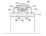
図8は本発明に係るレンズ装置の第3の実施形態を示す要部断面図であり、第1フォーカスリング120がスライド方向の中間位置に位置している状態に関して示している。
[Third Embodiment]
FIG. 8 is a cross-sectional view of an essential part showing a third embodiment of the lens apparatus according to the present invention, and shows a state in which the
第3の実施形態のレンズ装置は、主として第1の実施形態と第2の実施形態とを組み合わせたものである。尚、図8において、第1の実施形態と第2の実施形態と共通する部分には同一の符号を付し、その詳細な説明は省略する。 The lens apparatus according to the third embodiment is a combination of the first embodiment and the second embodiment. In FIG. 8, the same reference numerals are given to portions common to the first embodiment and the second embodiment, and detailed description thereof is omitted.
図8に示すように第3の実施形態の第1フォーカスリング220は、第1の実施形態の第1フォーカスリング20の内周面(レンズ鏡胴本体110側の磁石112と対向する位置)に磁石122が配設されている点で、第1の実施形態の第1フォーカスリング20と相違する。
As shown in FIG. 8, the
これにより、第3の実施形態のレンズ装置の第1フォーカスリング220には、第1の実施形態と同様に、第1フォーカスリング220の両端面の磁石22、24と第2フォーカスリング30及び第3フォーカスリング40側の磁石32、42との間で発生する吸引力が加わるとともに、第2の実施形態と同様に、レンズ鏡胴本体110の外周面に設けた磁石112と第1フォーカスリング220の内周面に設けた磁石122との間で発生する磁力(反発力等)によるスライド方向への付勢力が加わることになる。
As a result, the
次に、上記構成の第3の実施形態のレンズ装置の作用について説明する。 Next, the operation of the lens apparatus according to the third embodiment having the above-described configuration will be described.
図8は、第1フォーカスリング220がスライド方向(矢印AB方向)の中間位置に位置している状態に関して示している。この状態は、第1、第2の実施形態と同様に不安定な状態であるため、通常、この中間位置で第1フォーカスリング220が停止することはない。
FIG. 8 shows a state in which the
図9及び図10は、それぞれ本発明に係るレンズ装置の第3の実施形態を示す要部断面図であり、第1フォーカスリング220がスライド方向(矢印A方向)の一端の第1のスライド位置に位置している状態、及び第1フォーカスリング220がスライド方向(矢印B方向)の他端の第2のスライド位置に位置している状態に関して示している。
FIG. 9 and FIG. 10 are cross-sectional views showing the principal part of a third embodiment of the lens apparatus according to the present invention, respectively, and the
図9に示すように、第1フォーカスリング220が手動により矢印A方向にスライド操作され、図8に示した中間位置を越えると、第1フォーカスリング220は、磁石22と磁石32との間の吸引力、及び磁石112と磁石122との反発力により矢印A方向の移動端まで移動する。
As shown in FIG. 9, when the
第1フォーカスリング220の矢印A方向の移動端では、第1フォーカスリング220側の磁石22が第2フォーカスリング30側の磁石34に当接し、磁石22と磁石34とが吸着固定される。上記磁石22、32間の吸着力による当接時に、第1フォーカスリング220に触れている指先には、「カチッ」という感触が伝わり、良好な切替え感触が得られる。
At the moving end of the
一方、図9に示す状態から第1フォーカスリング220を、磁石22と磁石32との吸着力、及び磁石112と磁石122との間の磁力(反発力等)に抗して矢印B方向にスライド操作し、第1フォーカスリング220が、図8に示した中間位置を越えると、図10に示すように、磁石24と磁石42との間に生じる磁力(吸引力)、及び磁石112と磁石122との間の磁力(反発力等)により吸引されて矢印B方向の移動端(第2のスライド位置)まで移動する。
On the other hand, the
第1フォーカスリング220の矢印B方向の移動端では、第1フォーカスリング220側の磁石24が第3フォーカスリング40側の磁石42に当接し、磁石24と磁石42とが吸着固定される。上記磁石24、42間の吸着力による当接時に、第1フォーカスリング20に触れている指先には、「カチッ」という感触が伝わり、良好な切替え感触が得られる。
At the moving end of the
また、第1フォーカスリング220をスライドさせる際に、第1フォーカスリング220が中間位置に近づくにつれて大きな操作力を必要とし、中間位置を越えると、急激に操作力が不要となるとともに、第1フォーカスリング220は、磁石24と磁石42との間の磁力、磁石112と磁石122との間の磁力により矢印B方向の移動端まで移動する。この第1フォーカスリング220の操作力の変化により、良好な切替え感触が得られる。
Further, when the
[その他]
上記実施形態では、磁石として永久磁石を使用するようにしたが、これに限らず、電磁石を使用するようにしてもよい。
[Others]
In the above embodiment, a permanent magnet is used as a magnet. However, the present invention is not limited to this, and an electromagnet may be used.
また、第3フォーカスリングには、相対位置検出型センサと連結される歯車44が形成されているが、第1フォーカスリング側に相対位置検出型センサと常時連結される歯車を形成するようにしてもよい。この場合、第3フォーカスリングは、第1フォーカスリングがAF/MFモード(エンド端なし)に切り替えられたときの切替え感触を発生させるとともに、該第1フォーカスリングを保持するリング部材として機能することになる。また、第1フォーカスリングと連結される相対位置検出型センサは、第1フォーカスリングによりAF/MFモード(エンド端なし)に切り替えられているときに動作可能にする。
The third focus ring is formed with a
更に、この実施形態では、フォーカスリングのクリック機構について説明したが、これに限らず、レンズ鏡胴本体の周囲を回動するとともに、光軸方向にスライド移動するリング部材であれば、そのリング部材のスライド方向のクリック機構として適用できる。 Further, in this embodiment, the click mechanism of the focus ring has been described. However, the present invention is not limited to this, and any ring member that rotates around the lens barrel body and slides in the optical axis direction can be used. It can be applied as a click mechanism in the sliding direction.
また、本発明は上述した実施形態に限定されず、本発明の精神を逸脱しない範囲で種々の変形が可能であることは言うまでもない。 Moreover, it goes without saying that the present invention is not limited to the above-described embodiments, and various modifications can be made without departing from the spirit of the present invention.
10、110…レンズ鏡胴本体、20、120、220…第1フォーカスリング、22、24、32、42、112、122…磁石、30、130…第2フォーカスリング、40、140…第3フォーカスリング、34,44…歯車、124、126、132、142…クラッチ部
DESCRIPTION OF
Claims (7)
前記レンズ鏡胴本体に対して所定の回動範囲内のみで回動自在に配設された第2のリング部材であって、前記第1のリング部材が前記第1のスライド位置に移動すると、該第1のリング部材の一方の側面と当接可能に配設された第2のリング部材と、
前記レンズ鏡胴本体に対してエンドレス回転が可能に配設された第3のリング部材であって、前記第1のリング部材が前記第2のスライド位置に移動すると、該第1のリング部材の他方の側面と当接可能に配設された第3のリング部材と、
前記第1のリング部材のスライド方向の両端面に設けられた第1の磁性部材と、
前記第2のリング部材及び第3のリング部材の前記第1のリング部材の端面に対向する面に設けられた第2の磁性部材と、を備え、
前記第1、第2の磁性部材の少なくとも一方は磁石により構成され、前記第1のリング部材は、該第1のリング部材の第1のスライド位置への移動時又は第2のスライド位置への移動時に磁力により前記第2のリング部材又は第3のリング部材と吸着されることにより、第2のリング部材又は第3のリング部材と連動して回転するように構成されたことを特徴とするレンズ装置。 A first ring member arranged to be capable of endless rotation with respect to the lens barrel main body and slidable between a first slide position and a second slide position in the optical axis direction; ,
When the first ring member is moved to the first slide position, the second ring member is rotatably arranged only within a predetermined rotation range with respect to the lens barrel body. A second ring member arranged to be in contact with one side surface of the first ring member;
A third ring member arranged to be capable of endless rotation with respect to the lens barrel body, and when the first ring member moves to the second slide position, A third ring member arranged to be in contact with the other side surface;
A first magnetic member provided on both end faces of the first ring member in the sliding direction;
A second magnetic member provided on a surface of the second ring member and a third ring member facing the end surface of the first ring member;
At least one of the first and second magnetic members is composed of a magnet, and the first ring member is moved when the first ring member moves to the first slide position or to the second slide position. It is configured to rotate in conjunction with the second ring member or the third ring member by being attracted to the second ring member or the third ring member by a magnetic force during movement. Lens device.
前記レンズ鏡胴本体に対して所定の回動範囲内のみで回動自在に配設された第2のリング部材であって、前記第1のリング部材が前記第1のスライド位置に移動すると、該第1のリング部材の一方の側面と当接可能に配設された第2のリング部材と、
前記レンズ鏡胴本体に対してエンドレス回転が可能に配設された第3のリング部材であって、前記第1のリング部材が前記第2のスライド位置に移動すると、該第1のリング部材の他方の側面と当接可能に配設された第3のリング部材と、
前記レンズ鏡胴本体の外周面に設けられた第1の磁石と前記第1のリング部材の内周面に設けられた第2の磁石とからなる一対の第1及び第2の磁石であって、前記第1のリング部材が前記第1のスライド位置と第2のスライド位置との中間位置に位置するときに、互いに反発するようにそれぞれS極、N極が設けられ、前記第1のリング部材が前記中間位置からずれると、該第1のリング部材を前記第2のリング部材の端面又は第3のリング部材の端面に押圧するように磁力により付勢する第1及び第2の磁石と、
を備えたことを特徴とするレンズ装置。 A first ring member arranged to be capable of endless rotation with respect to the lens barrel main body and slidable between a first slide position and a second slide position in the optical axis direction; ,
When the first ring member is moved to the first slide position, the second ring member is rotatably arranged only within a predetermined rotation range with respect to the lens barrel body. A second ring member arranged to be in contact with one side surface of the first ring member;
A third ring member arranged to be capable of endless rotation with respect to the lens barrel body, and when the first ring member moves to the second slide position, A third ring member arranged to be in contact with the other side surface;
A pair of first and second magnets comprising a first magnet provided on the outer peripheral surface of the lens barrel body and a second magnet provided on the inner peripheral surface of the first ring member; When the first ring member is located at an intermediate position between the first slide position and the second slide position, an S pole and an N pole are provided so as to repel each other, and the first ring First and second magnets that are biased by a magnetic force to press the first ring member against the end surface of the second ring member or the end surface of the third ring member when the member is displaced from the intermediate position; ,
A lens device comprising:
前記レンズ鏡胴本体に対して所定の回動範囲内のみで回動自在に配設された第2のリング部材であって、前記第1のリング部材が前記第1のスライド位置に移動すると、該第1のリング部材の一方の側面と当接可能に配設された第2のリング部材と、
前記レンズ鏡胴本体に対してエンドレス回転が可能に配設された第3のリング部材であって、前記第1のリング部材が前記第2のスライド位置に移動すると、該第1のリング部材の他方の側面と当接可能に配設された第3のリング部材と、
前記レンズ鏡胴本体の外周面に設けられた第1の磁石と前記第1のリング部材の内周面に設けられた第2の磁石とからなる一対の第1及び第2の磁石であって、前記第1のリング部材が前記第1のスライド位置と第2のスライド位置との中間位置に位置するときに、互いに反発するようにそれぞれS極、N極が設けられ、前記第1のリング部材が前記中間位置からずれると、該第1のリング部材を前記第2のリング部材の端面又は第3のリング部材の端面に押圧するように磁力により付勢する第1及び第2の磁石と、
前記第1のリング部材のスライド方向の両端面に設けられた第1の磁性部材と、
前記第2のリング部材及び第3のリング部材の前記第1のリング部材の端面に対向する面に設けられた第2の磁性部材と、を備え、
前記第1、第2の磁性部材の少なくとも一方は磁石により構成され、前記第1のリング部材は、該第1のリング部材の第1のスライド位置への移動時又は第2のスライド位置への移動時に磁力により前記第2のリング部材又は第3のリング部材と吸着されることを特徴とするレンズ装置。 A first ring member arranged to be capable of endless rotation with respect to the lens barrel main body and slidable between a first slide position and a second slide position in the optical axis direction; ,
When the first ring member is moved to the first slide position, the second ring member is rotatably arranged only within a predetermined rotation range with respect to the lens barrel body. A second ring member arranged to be in contact with one side surface of the first ring member;
A third ring member arranged to be capable of endless rotation with respect to the lens barrel body, and when the first ring member moves to the second slide position, A third ring member arranged to be in contact with the other side surface;
A pair of first and second magnets comprising a first magnet provided on the outer peripheral surface of the lens barrel body and a second magnet provided on the inner peripheral surface of the first ring member; When the first ring member is located at an intermediate position between the first slide position and the second slide position, an S pole and an N pole are provided so as to repel each other, and the first ring First and second magnets that are biased by a magnetic force to press the first ring member against the end surface of the second ring member or the end surface of the third ring member when the member is displaced from the intermediate position; ,
A first magnetic member provided on both end faces of the first ring member in the sliding direction;
A second magnetic member provided on a surface of the second ring member and a third ring member facing the end surface of the first ring member;
At least one of the first and second magnetic members is composed of a magnet, and the first ring member is moved when the first ring member moves to the first slide position or to the second slide position. A lens device that is attracted to the second ring member or the third ring member by a magnetic force during movement.
Priority Applications (1)
| Application Number | Priority Date | Filing Date | Title |
|---|---|---|---|
| JP2011070296A JP5555195B2 (en) | 2011-03-28 | 2011-03-28 | Lens device |
Applications Claiming Priority (1)
| Application Number | Priority Date | Filing Date | Title |
|---|---|---|---|
| JP2011070296A JP5555195B2 (en) | 2011-03-28 | 2011-03-28 | Lens device |
Publications (2)
| Publication Number | Publication Date |
|---|---|
| JP2012203340A true JP2012203340A (en) | 2012-10-22 |
| JP5555195B2 JP5555195B2 (en) | 2014-07-23 |
Family
ID=47184373
Family Applications (1)
| Application Number | Title | Priority Date | Filing Date |
|---|---|---|---|
| JP2011070296A Expired - Fee Related JP5555195B2 (en) | 2011-03-28 | 2011-03-28 | Lens device |
Country Status (1)
| Country | Link |
|---|---|
| JP (1) | JP5555195B2 (en) |
Cited By (1)
| Publication number | Priority date | Publication date | Assignee | Title |
|---|---|---|---|---|
| US20210215999A1 (en) * | 2018-10-25 | 2021-07-15 | Fujifilm Corporation | Lens barrel |
Citations (5)
| Publication number | Priority date | Publication date | Assignee | Title |
|---|---|---|---|---|
| JPS62221883A (en) * | 1986-03-19 | 1987-09-29 | Olympus Optical Co Ltd | Ultrasonic wave motor |
| JPH04344607A (en) * | 1991-05-21 | 1992-12-01 | Asahi Optical Co Ltd | Operating mechanism for lens barrel |
| JP2008102207A (en) * | 2006-10-17 | 2008-05-01 | Sony Corp | Lens device and imaging apparatus |
| JP2010176971A (en) * | 2009-01-28 | 2010-08-12 | Omron Corp | Operation mode selecting device and electronic device using the same |
| JP2011043706A (en) * | 2009-08-21 | 2011-03-03 | Fujifilm Corp | Lens device |
-
2011
- 2011-03-28 JP JP2011070296A patent/JP5555195B2/en not_active Expired - Fee Related
Patent Citations (5)
| Publication number | Priority date | Publication date | Assignee | Title |
|---|---|---|---|---|
| JPS62221883A (en) * | 1986-03-19 | 1987-09-29 | Olympus Optical Co Ltd | Ultrasonic wave motor |
| JPH04344607A (en) * | 1991-05-21 | 1992-12-01 | Asahi Optical Co Ltd | Operating mechanism for lens barrel |
| JP2008102207A (en) * | 2006-10-17 | 2008-05-01 | Sony Corp | Lens device and imaging apparatus |
| JP2010176971A (en) * | 2009-01-28 | 2010-08-12 | Omron Corp | Operation mode selecting device and electronic device using the same |
| JP2011043706A (en) * | 2009-08-21 | 2011-03-03 | Fujifilm Corp | Lens device |
Cited By (3)
| Publication number | Priority date | Publication date | Assignee | Title |
|---|---|---|---|---|
| US20210215999A1 (en) * | 2018-10-25 | 2021-07-15 | Fujifilm Corporation | Lens barrel |
| JP2022097558A (en) * | 2018-10-25 | 2022-06-30 | 富士フイルム株式会社 | Operating member |
| JP7266737B2 (en) | 2018-10-25 | 2023-04-28 | 富士フイルム株式会社 | operating member |
Also Published As
| Publication number | Publication date |
|---|---|
| JP5555195B2 (en) | 2014-07-23 |
Similar Documents
| Publication | Publication Date | Title |
|---|---|---|
| US7755697B2 (en) | Webcam with moveable zoom lens | |
| JP5334311B2 (en) | Lens device | |
| KR20130015666A (en) | Auto focusing apparatus for micro camera module | |
| JP2008032992A (en) | Drive unit, limiting device, and method for controlling them | |
| JP5555196B2 (en) | Lens device | |
| JP2005003867A (en) | Two-position stabilizer and lens device using the same | |
| JP5555195B2 (en) | Lens device | |
| JP2011043705A (en) | Lens device | |
| JP5479039B2 (en) | Lens device | |
| JP5479034B2 (en) | Lens device | |
| JP2011033888A (en) | Lens device | |
| JP2011033886A (en) | Lens device | |
| JP2011033885A (en) | Lens device | |
| JP2006313235A (en) | Operation device of television lens | |
| JP2011048080A (en) | Lens device | |
| JP2013050688A (en) | Lens device | |
| JP5300632B2 (en) | Lens device | |
| JP2008225161A (en) | Lens barrel | |
| JP2009015001A (en) | Lens device | |
| JP2011064972A (en) | Lens device | |
| JP6633490B2 (en) | Lens drive mechanism, and lens unit and camera having the same | |
| JP2006195179A (en) | Lens driving device | |
| JP2011043582A (en) | Lens device | |
| JP2015082084A (en) | Optical device | |
| JP5651087B2 (en) | Lens device |
Legal Events
| Date | Code | Title | Description |
|---|---|---|---|
| A621 | Written request for application examination |
Free format text: JAPANESE INTERMEDIATE CODE: A621 Effective date: 20130730 |
|
| A977 | Report on retrieval |
Free format text: JAPANESE INTERMEDIATE CODE: A971007 Effective date: 20140430 |
|
| TRDD | Decision of grant or rejection written | ||
| A01 | Written decision to grant a patent or to grant a registration (utility model) |
Free format text: JAPANESE INTERMEDIATE CODE: A01 Effective date: 20140515 |
|
| A61 | First payment of annual fees (during grant procedure) |
Free format text: JAPANESE INTERMEDIATE CODE: A61 Effective date: 20140530 |
|
| R150 | Certificate of patent or registration of utility model |
Ref document number: 5555195 Country of ref document: JP Free format text: JAPANESE INTERMEDIATE CODE: R150 |
|
| R250 | Receipt of annual fees |
Free format text: JAPANESE INTERMEDIATE CODE: R250 |
|
| LAPS | Cancellation because of no payment of annual fees |