JP2012202446A - Cushion mechanism of fluid pressure cylinder - Google Patents
Cushion mechanism of fluid pressure cylinder Download PDFInfo
- Publication number
- JP2012202446A JP2012202446A JP2011065684A JP2011065684A JP2012202446A JP 2012202446 A JP2012202446 A JP 2012202446A JP 2011065684 A JP2011065684 A JP 2011065684A JP 2011065684 A JP2011065684 A JP 2011065684A JP 2012202446 A JP2012202446 A JP 2012202446A
- Authority
- JP
- Japan
- Prior art keywords
- cushion
- bypass passage
- cylinder
- hole
- spool
- Prior art date
- Legal status (The legal status is an assumption and is not a legal conclusion. Google has not performed a legal analysis and makes no representation as to the accuracy of the status listed.)
- Granted
Links
Images


Landscapes
- Actuator (AREA)
Abstract
Description
本発明は、シリンダチューブにおけるピストンロッドのストローク端付近でピストンロッドを減速させる流体圧シリンダのクッション機構に関するものである。 The present invention relates to a fluid pressure cylinder cushion mechanism that decelerates a piston rod near the stroke end of the piston rod in a cylinder tube.
例えば油圧ショベル等に用いられる流体圧シリンダ(油圧シリンダ)にあっては、ピストンロッドのストローク端付近でクッション圧力を発生させてピストンロッドを減速させるクッション機構を備えている。 For example, a fluid pressure cylinder (hydraulic cylinder) used in a hydraulic excavator or the like includes a cushion mechanism that generates a cushion pressure near the stroke end of the piston rod to decelerate the piston rod.
従来、この種のクッション機構として、ピストンロッドがストローク端付近に来たときに、作動流体を通過させるクッション間隙を画成するクッションベアリングと、このクッションベアリングに対峙するように介装されるスペーサ部材とを備えるものがある(特許文献1参照)。 Conventionally, as this kind of cushion mechanism, when the piston rod comes near the stroke end, a cushion bearing that defines a cushion gap through which the working fluid passes, and a spacer member that is interposed so as to face the cushion bearing (See Patent Document 1).
このクッション機構は、ピストンロッドがストローク端付近に来たときに、クッションベアリングがスペーサ部材の内側に入ってクッション間隙が画成され、このクッション間隙が作動流体の流れに抵抗を付与することによってクッション圧力が発生する。 In this cushion mechanism, when the piston rod comes close to the stroke end, the cushion bearing enters the inside of the spacer member to define a cushion gap, and this cushion gap provides resistance to the flow of the working fluid. Pressure is generated.
しかしながら、このような従来のクッション機構にあっては、クッション間隙を画成するクッションベアリング等の寸法バラツキによってクッション圧力が設定値からズレる可能性がある。 However, in such a conventional cushion mechanism, there is a possibility that the cushion pressure deviates from the set value due to dimensional variations of a cushion bearing or the like that defines the cushion gap.
本発明は上記の問題点に鑑みてなされたものであり、クッション圧力を調整できる流体圧シリンダのクッション機構を提供することを目的とする。 The present invention has been made in view of the above problems, and an object thereof is to provide a cushion mechanism for a fluid pressure cylinder capable of adjusting the cushion pressure.
本発明は、シリンダチューブに対するピストンロッドのストローク端付近でピストンロッドを減速させる流体圧シリンダのクッション機構であって、作動流体の流れを絞るクッション間隙と、このクッション間隙を迂回する作動油を導くバイパス通路と、このバイパス通路が開口するバルブ収容孔と、このバルブ収容孔に収容されてバイパス通路の通路開口面積を増減するスプールと、スプールを支持するセットスクリュと、このセットスクリュを螺合させるネジ孔とを備える構成とした。 The present invention is a fluid pressure cylinder cushion mechanism that decelerates a piston rod in the vicinity of the stroke end of the piston rod relative to the cylinder tube, and includes a cushion gap that restricts the flow of the working fluid, and a bypass that guides hydraulic oil that bypasses the cushion gap A passage, a valve housing hole in which the bypass passage is opened, a spool that is housed in the valve housing hole to increase or decrease the passage opening area of the bypass passage, a set screw that supports the spool, and a screw that is screwed into the set screw It was set as the structure provided with a hole.
本発明によると、ネジ孔に対するセットスクリュの螺合位置を調整することにより、スプールがバルブ収容孔にて変位し、バイパス通路の通路開口面積を変えられる。こうしてクッション圧力が調整されることにより、クッション間隙を画成する部材の寸法バラツキに起因するクッション圧力の過不足が解消される。 According to the present invention, by adjusting the screwing position of the set screw with respect to the screw hole, the spool is displaced in the valve housing hole, and the passage opening area of the bypass passage can be changed. By adjusting the cushion pressure in this way, the excess or deficiency of the cushion pressure due to the dimensional variation of the members that define the cushion gap is eliminated.
以下、本発明の実施形態を添付図面に基づいて説明する。 Hereinafter, embodiments of the present invention will be described with reference to the accompanying drawings.
(第1実施形態)
図1に示す油圧シリンダ1は、例えば油圧ショベルのアームシリンダとして用いられる。油圧シリンダ1が伸縮作動することにより、油圧ショベルのアームが回動する。
(First embodiment)
A hydraulic cylinder 1 shown in FIG. 1 is used as an arm cylinder of a hydraulic excavator, for example. As the hydraulic cylinder 1 expands and contracts, the arm of the hydraulic excavator rotates.
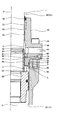
油圧シリンダ(流体圧シリンダ)1は、筒状をしたシリンダチューブ10と、このシリンダチューブ10内にロッド室2とエンド室3を仕切るピストン20と、このピストン20に連結されるピストンロッド30とを備える。ロッド室2とエンド室3は、それぞれ図示しない油圧源(作動流体圧源)に連通し、この油圧源から導かれる作動油圧(作動流体圧)によってピストンロッド30が中心軸O方向に移動して伸縮作動する。図1はピストンロッド30がストローク端付近に来た状態を示している。
The hydraulic cylinder (fluid pressure cylinder) 1 includes a
なお、作動油としてオイルの代わりに例えば水溶性代替液等の作動流体を用いても良い。 Note that a working fluid such as a water-soluble alternative liquid may be used instead of the oil as the working oil.
円筒状のシリンダチューブ10の端部にはシリンダヘッド40が複数のボルト41を介して締結される。
A
シリンダチューブ10の開口端には、ピストンロッド30を摺動可能に挿通させるシリンダヘッド40が設けられる。
A
シリンダヘッド40は、シリンダ内周面11に嵌合される円筒状のヘッド嵌合部42を有する。ヘッド嵌合部42とシリンダ内周面11の間にシールリング9が介装され、ロッド室2が密封される。
The
シリンダヘッド40の内周には、軸受59、サブシール56、メインシール57、ダストシール58がそれぞれ介装され、これらがピストンロッド30のロッド外周面31に摺接する。軸受59がロッド外周面31に摺接することにより、ピストンロッド30がシリンダチューブ10の中心軸O方向に平行移動するように支持される。
A
シリンダヘッド40のフランジ面46には給排口43が開口し、この給排口43に油圧源に連通する図示しない油圧配管が接続される。
A supply /
シリンダヘッド40の内周には、ヘッド環状溝45とヘッド内周面44が形成され、これらとピストンロッド30との間に給排通路5が画成される。ヘッド環状溝45に給排口43の一端が開口される。ヘッド内周面44は、中心軸Oを中心とする円筒面状に形成される。
A head annular groove 45 and a head inner
図1にてピストンロッド30が下方に移動する油圧シリンダ1の収縮作動時、油圧源から油圧配管を通って供給される加圧作動油が、給排口43と給排通路5を通ってロッド室2に流入する(図中白抜き矢印参照)。
In the contraction operation of the hydraulic cylinder 1 in which the
一方、図1にてピストンロッド30が上方に移動する油圧シリンダ1の伸張作動時、そのストローク中程では、ロッド室2の作動油が、給排通路5、給排口43、油圧配管を通って油圧源へと流出する(図中白抜き矢印参照)。
On the other hand, when the hydraulic cylinder 1 in which the
油圧シリンダ1にはピストンロッド30がストローク端付近に来たときにピストンロッド30を減速させるクッション機構6が設けられる。
The hydraulic cylinder 1 is provided with a
クッション機構6は、ピストンロッド30がストローク端付近に来たときに画成されるクッション間隙8を備える。
The
ピストンロッド30には円筒状のクッションベアリング60が取り付けられる。このクッションベアリング60は、ピストンロッド30の端部の外周面に嵌合し、ピストンロッド30の環状段部32とピストン20の上端面22との間に挟持される。
A cylindrical cushion bearing 60 is attached to the
なお、これに限らず、クッションベアリングがピストンロッド30に一体形成される構成としてもよい。
The configuration is not limited to this, and the cushion bearing may be formed integrally with the
また、クッションベアリング60はピストンロッド30に間隙を持って嵌合し、クッションベアリング60がピストンロッド30の半径方向について移動可能にフローティング支持される構成してもよい。
The cushion bearing 60 may be fitted to the
油圧シリンダ1の伸張作動時に、ピストンロッド30がストローク端付近に来たときに、クッションベアリング60がヘッド内周面44の内側に入ることによって、両者の間にクッション間隙8が画成される。クッションベアリング60がヘッド内周面44の内側に入ると、ロッド室2の作動油が、クッション間隙8と給排通路5と油圧配管を通って油圧源へと流出する。このクッション間隙8がロッド室2から給排通路5を通って流出する作動油の流れに抵抗を付与し、ロッド室2の圧力(以下、クッション圧力という)が上昇することにより、ピストンロッド30を減速する。
When the
クッションベアリング60は、その外周面としてベアリング外周面61を有する。このベアリング外周面61は中心軸Oを中心とする円筒面状に形成される。
The cushion bearing 60 has a bearing outer
ベアリング外周面61の外径は、ロッド外周面31の外径より大きく、かつヘッド内周面44の内径より小さく形成される。ストローク端付近でクッションベアリング60がヘッド内周面44に入ることによって、両者の間にクッション間隙8が画成される。
The outer diameter of the bearing outer
クッションベアリング60には、ベアリング外周面61を部分的に削除した図示しない割円部(切り欠き)が形成される。ピストンロッド30がストローク端に近づくのにしたがって、割円部によって画成されるクッション間隙8の流路断面積が漸次減少するようになっている。クッション機構6に要求される減速特性に応じて、クッション間隙8のクリアランス(間隙幅)、割円部の形状が設定される。
The cushion bearing 60 is formed with a not-shown split circle (notch) in which the bearing outer
しかし、クッション間隙8の微少なクリアランスは、クッション間隙8を画成するベアリング外周面61、ヘッド内周面44等の寸法バラツキによって設定値からズレる可能性がある。
However, the slight clearance of the
これに対処して、クッション機構6には、クッション間隙8を迂回する作動油を導くバイパス通路50と、このバイパス通路50の通路開口面積を作業者が調整するバイパス絞り調整機構65とが設けられる。
In response to this, the
バイパス通路50は、シリンダヘッド40に形成される通孔51、52、切り欠き部48によって画成される。この通孔51、52は、中心軸Oと平行な直線上に延びるように形成される。通孔51の一端が給排口43に開口し、通孔52の一端が切り欠き部48を介してロッド室2に開口する。これにより、バイパス通路50は、給排口43とロッド室2を連通する。
The
油圧シリンダ1が最も伸長した状態では、ピストン20の上端面22がシリンダヘッド40の下端面49に当接するが、切り欠き部48によってクッション間隙8及びバイパス通路50がロッド室2と連通される。
In the state in which the hydraulic cylinder 1 is most extended, the
図2は図1の一部を拡大した断面図である。油圧シリンダ1の伸長作動時に、ロッド室2の作動油は、図中矢印で示すように、クッション間隙8を通るとともに、バイパス通路50を通って給排口43へと流れる。
FIG. 2 is an enlarged cross-sectional view of a part of FIG. During the extension operation of the hydraulic cylinder 1, the hydraulic oil in the
バイパス絞り調整機構65は、バイパス通路50の通孔51と交差するバルブ収容孔53と、このバルブ収容孔53に収容されてバイパス通路50の通路開口面積を可変とするスプール64と、シリンダヘッド40に対してスプール64を支持するセットスクリュ63と、このセットスクリュ63を螺合させるネジ孔54とを備える。このセットスクリュ63は、ネジ孔54に対する螺合位置が作業者によって調整される構成する。
The bypass
バルブ収容孔53は、中心軸Oに対して略直交する直線上に延びるように形成され、バイパス通路50の通孔51に対しても略直交する。ネジ孔54は、バルブ収容孔53と同軸上に形成される。
The
シリンダヘッド40には、ネジ孔54と同軸上に作業穴(ネジ孔)55が形成される。この作業穴55はシリンダヘッド40の外壁面に開口し、栓体74が取り付けられる。この栓体74は作業穴55に螺合して取り付けられ、バルブ収容孔53を閉塞することにより、作動油がバルブ収容孔53を通って外部へと洩れ出さないようになっている。
A working hole (screw hole) 55 is formed in the
スプール64は、一対のランド部67、69と、このランド部67、69を結ぶ弁軸部68と有する。このランド部67、69がバイパス通路50(通孔51)を挟んでバルブ収容孔53に嵌合され、ランド部67、69の軸方向の位置に応じてバイパス通路50の開口面積を増減する可変絞りを構成する。
The
セットスクリュ63は、ネジ孔54に螺合するヘッド部72と、スプール64の端面64aに当接する軸部70とを有する。ヘッド部72の外周にはネジ孔54に螺合する雄ねじが形成され、ヘッド部72の端面には工具に係合する工具係合部71が開口される。例えば、工具係合部71は六角穴であり、これに係合する工具は六角レンチが用いられる。
The
スプール64の端面64bとバルブ収容孔53の底部53aの間にはコイル状のスプリング66が圧縮して介装される。スプール64は、このスプリング66のバネ力によってセットスクリュ63に押し付けられる。
A
作業者がヘッド部72の螺合位置を変えてセットスクリュ63をその軸方向に移動することにより、スプリング66によってこれに押し付けられるスプール64が一緒に移動する。これにより、ランド部67、69の一方がバイパス通路50に臨み、バイパス通路50の開口面積が減らされるようになっている。
When the operator changes the screwing position of the
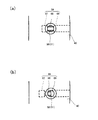
図3の(a)、(b)は、図1の矢印A方向から見た図であり、スプール64の動作を示しており、斜線部分がバイパス通路50の開口部(流路部)を示している。
FIGS. 3A and 3B are views seen from the direction of arrow A in FIG. 1, showing the operation of the
図3の(a)は、スプール64が全開位置にある様子を示している。この状態では、ランド部67、69がバイパス通路50の両側に位置しており、バイパス通路50の開口面積がランド部67、69によって削減されることはない。
FIG. 3A shows a state in which the
図3の(b)は、スプール64が半開位置にある様子を示している。この状態では、ランド部69がバイパス通路50に臨んでおり、バイパス通路50の開口面積がランド部69によって半分程度削減されている。この状態から、スプール64が図にて右方向に移動することによってバイパス通路50の開口面積が増加する一方、左方向に移動することによってバイパス通路50の開口面積が減少する。
FIG. 3B shows a state where the
油圧シリンダ1の製造時には、油圧シリンダ1の組み立て工程が終了した後に、油圧シリンダ1の作動特性を測定する試験工程が行われ、作業者がこの測定結果に基づいてバイパス絞り調整機構65の調整をする調整工程が行われる。
When the hydraulic cylinder 1 is manufactured, after the assembly process of the hydraulic cylinder 1 is completed, a test process for measuring the operating characteristics of the hydraulic cylinder 1 is performed, and the operator adjusts the bypass
試験工程では、油圧シリンダ1を図示しないアクチュエータによって所定の条件で伸縮作動させ、ピストンロッド30のストロークに応じた伸縮作動速度を測定する。
In the test process, the hydraulic cylinder 1 is expanded and contracted under a predetermined condition by an actuator (not shown), and the expansion and contraction operation speed corresponding to the stroke of the
調整工程では、ストローク端付近の減速度の測定値と設定値との差に応じて、スプール64の開度が調整される。この調整は、作業者が工具を作業穴55から差し込んでセットスクリュ63の工具係合部71に係合させてセットスクリュ63を回転し、セットスクリュ63の螺合位置を変えることによって行われる。
In the adjustment step, the opening degree of the
減速度の測定値が設定値より低い場合には、バイパス通路50の開口面積が所定の基準開度より小さくなるように調整され、クッション圧力が高められる。一方、減速度の測定値が設定値より高い場合には、バイパス通路50の開口面積が所定の基準開度より大きくなるように調整され、過大なクッション圧力が下げられる。
When the measured value of the deceleration is lower than the set value, the opening area of the
こうして、油圧シリンダ1は、製品毎にバイパス通路50の開口面積の調整が行われることにより、クッション間隙8を画成するベアリング外周面61、ヘッド内周面44等の寸法バラツキに起因するクッション圧力の過不足が解消され、ストローク端付近の減速度を設定値に近づけられる。
Thus, the hydraulic cylinder 1 adjusts the opening area of the
以上のように本実施形態では、シリンダチューブ10に対するピストンロッド30のストローク端付近でピストンロッド30を減速させる流体圧シリンダ1のクッション機構6であって、作動流体の流れを絞るクッション間隙8と、このクッション間隙8を迂回する作動油を導くバイパス通路50と、このバイパス通路50が開口するバルブ収容孔53と、このバルブ収容孔53に収容されてバイパス通路50の通路開口面積を増減するスプール64と、スプール64を支持するセットスクリュ63と、このセットスクリュ63を螺合させるネジ孔54とを備える構成とした。
As described above, in the present embodiment, the
上記構成に基づき、ネジ孔54に対するセットスクリュ63の螺合位置を調整することにより、スプール64がバルブ収容孔53にて変位し、バイパス通路50の通路開口面積が変えられる。これにより、バイパス通路50を流れる作動流体に付与される抵抗が変えられることによってクッション圧力が調整されるため、クッション間隙8を画成する部材の寸法バラツキに起因するクッション圧力の過不足が解消される。これにより、クッション間隙8を画成する部材の寸法精度を高めることなく、クッション性能のバラツキを抑えられるため、製品のコストダウンがはかれる。
Based on the above configuration, by adjusting the screwing position of the
(第2実施形態)
次に図4〜6に示す他の実施形態を説明する。これは図1〜3の実施形態と基本的に同じ構成を有し、相違する部分のみを説明する。なお、前記実施形態と同一構成部には同一符号を付す。
(Second Embodiment)
Next, another embodiment shown in FIGS. 4 to 6 will be described. This has basically the same configuration as the embodiment of FIGS. 1 to 3, and only the differences will be described. In addition, the same code | symbol is attached | subjected to the same structure part as the said embodiment.
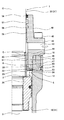
図4に示すように、シリンダチューブ10の内側にホルダ23が介装される。ホルダ23は、中心軸Oを中心とする円環状に形成され、シリンダ内周面11に、シリンダヘッド40のヘッド嵌合部42と並んで嵌合される。ホルダ23は、その下端外周部がシリンダ内周面11のテーパ面12に着座し、その上端面にシリンダヘッド40の下端面47が当接し、両者の間に挟持される。
As shown in FIG. 4, a
なお、ホルダ23の固定方法については、これに限らず、他に例えば、シリンダヘッド40とホルダ23とを図示しないボルトにて固定してもよい。この場合に、シリンダチューブ10の内面にテーパ面12を形成する必要がなくなる。
In addition, about the fixing method of the
図5は図4の一部を拡大した断面図である。ホルダ23の内周面24は、中心軸Oを中心とする円筒面状に形成される。油圧シリンダ1の伸張作動時に、ピストンロッド30がストローク端付近に来たときに、クッションベアリング60がホルダ23の内側に入ることによって、両者の間にクッション間隙8が画成される。
FIG. 5 is an enlarged cross-sectional view of a part of FIG. The inner
ホルダ23にバイパス通路28が設けられる。このバイパス通路28は、シリンダヘッド40に形成される切り欠き部25、通孔26、27、切り欠き部29によって画成される。この通孔26、27は、中心軸Oと平行な直線上に延びるように形成される。通孔26の一端が切り欠き部25を介して給排通路5に開口し、通孔27の一端が切り欠き部29を介してロッド室2に開口する。これにより、バイパス通路28は、給排通路5を介して給排口43とロッド室2を連通する。
A
油圧シリンダ1が最も収縮した状態では、ピストン20の上端面22がホルダ23の下端面39に当接するが、切り欠き部29によってクッション間隙8及びバイパス通路50がロッド室2と連通される。
In the state in which the hydraulic cylinder 1 is most contracted, the
油圧シリンダ1の収縮作動時に、ロッド室2の作動油は、図2に矢印で示すように、クッション間隙8を通るとともに、バイパス通路28を通って給排通路5へと流れる。
During the contraction operation of the hydraulic cylinder 1, the hydraulic oil in the
図5に示すように、バイパス絞り調整機構65は、バイパス通路50の通孔51と交差するバルブ収容孔33と、このバルブ収容孔33に収容されてバイパス通路28の通路開口面積を可変とするスプール64と、ホルダ23に対してスプール64を支持するセットスクリュ63と、このセットスクリュ63を螺合させるネジ孔34とを備える。このセットスクリュ63は、ネジ孔34に対する螺合位置が作業者によって調整される構成する。
As shown in FIG. 5, the bypass
ホルダ23には、バルブ収容孔33が中心軸Oに対して略直交する直線上に延びるように形成されるとともに、ネジ孔34がバルブ収容孔33と同軸上に形成される。
In the
スプール64とセットスクリュ63は前記実施形態と同様の構成を有する。作業者がヘッド部72の螺合位置を変えてセットスクリュ63をその軸方向に移動することにより、ランド部67、69の一方がバイパス通路28に臨み、バイパス通路28の開口面積が増減するようになっている。
The
シリンダチューブ10には、ネジ孔34と同軸上に作業穴(ネジ孔)55が形成される。この作業穴55は、その一端がホルダ23のネジ孔34に対峙して開口し、その他端がシリンダチューブ10の外壁面に開口し、栓体74が取り付けられる。
A working hole (screw hole) 55 is formed in the
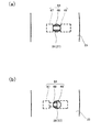
図6の(a)、(b)は、図4の矢印A方向から見た図であり、スプール64の動作を示しており、斜線部分がバイパス通路28の開口部(流路部)を示している。
6A and 6B are views seen from the direction of arrow A in FIG. 4, showing the operation of the
図6の(a)は、スプール64が全開位置にある様子を示している。この状態では、ランド部67、69がバイパス通路28の両側に位置しており、バイパス通路28の開口面積がランド部67、69によって削減されることはない。
FIG. 6A shows a state where the
図6の(b)は、スプール64が半開位置にある様子を示している。この状態では、ランド部69がバイパス通路28に臨んでおり、バイパス通路28の開口面積がランド部69によって半分程度削減されている。この状態から、スプール64が図にて右方向に移動することによってバイパス通路28の開口面積が増加し、左方向に移動することによってバイパス通路28の開口面積が減少する。
FIG. 6B shows a state where the
以上のように本実施形態では、シリンダチューブ10の内側に介装されるホルダ23を備え、このホルダ23にバイパス絞り調整機構65が介装される構成とした。
As described above, in the present embodiment, the
上記構成に基づき、ホルダ23がシリンダヘッド40と別体で形成されるため、要求される減速特性に応じたホルダ23をシリンダチューブ10の内側に介装することが可能となり、バイパス絞り調整機構65の交換が容易に行われる。また、ホルダ23を追加することにより、シリンダヘッド40の基本形状を変更することなく実施することが可能となり、製品のコストアップを抑えられる。
Based on the above configuration, since the
本実施形態では、ホルダ23の内周面24によってクッション間隙8が画成される構成とした。
In the present embodiment, the
上記構成に基づき、流体圧シリンダ1にクッション機構6を備える必要がない場合には、ホルダ23を外すことによって容易に対応できる。また、ホルダ23を交換することにより、クッション間隙8のクリアランスを容易に変更できる。
Based on the above configuration, when the fluid pressure cylinder 1 does not need to include the
なお、本発明は、流体圧シリンダの収縮作動時におけるピストンロッドのストローク端付近でピストンロッドを減速させるクッション機構(図示せず)に適用することもできる。 The present invention can also be applied to a cushion mechanism (not shown) that decelerates the piston rod in the vicinity of the stroke end of the piston rod during the contraction operation of the fluid pressure cylinder.
本発明は上記の実施形態に限定されずに、その技術的な思想の範囲内において種々の変更がなしうることは明白である。 The present invention is not limited to the above-described embodiment, and it is obvious that various modifications can be made within the scope of the technical idea.
1 油圧シリンダ(流体圧シリンダ)
5 給排通路
6 クッション機構
8 クッション間隙
10 シリンダチューブ
23 ホルダ
28、50 バイパス通路
33、53 バルブ収容孔
34、54 ネジ孔
55 作業穴
30 ピストンロッド
40 シリンダヘッド
43 給排口
60 クッションベアリング
61 ベアリング外周面
63 セットスクリュ
64 スプール
65 バイパス絞り調整機構
66 スプリング
1 Hydraulic cylinder (fluid pressure cylinder)
5 Supply /
Claims (3)
作動流体の流れを絞るクッション間隙と、
このクッション間隙を迂回する作動油を導くバイパス通路と、
このバイパス通路が開口するバルブ収容孔と、
このバルブ収容孔に収容されてバイパス通路の通路開口面積を増減するスプールと、
スプールを支持するセットスクリュと、
このセットスクリュを螺合させるネジ孔とを備えることを特徴とする流体圧シリンダのクッション機構。 A fluid pressure cylinder cushion mechanism that decelerates the piston rod near the stroke end of the piston rod relative to the cylinder tube,
A cushion gap that restricts the flow of the working fluid;
A bypass passage for guiding hydraulic oil that bypasses the cushion gap;
A valve housing hole in which the bypass passage opens;
A spool that is housed in the valve housing hole and increases or decreases the passage opening area of the bypass passage;
A set screw that supports the spool;
A cushion mechanism for a fluid pressure cylinder, comprising: a screw hole into which the set screw is screwed.
前記ホルダに前記バイパス通路が形成されるとともに前記バイパス絞り調整機構が介装されることを特徴とする請求項1に記載の流体圧シリンダのクッション機構。 A holder interposed inside the cylinder tube;
2. The hydraulic cylinder cushion mechanism according to claim 1, wherein the bypass passage is formed in the holder and the bypass throttle adjusting mechanism is interposed.
Priority Applications (4)
| Application Number | Priority Date | Filing Date | Title |
|---|---|---|---|
| JP2011065684A JP5583623B2 (en) | 2011-03-24 | 2011-03-24 | Cushion mechanism of fluid pressure cylinder |
| PCT/JP2012/055870 WO2012128049A1 (en) | 2011-03-24 | 2012-03-07 | Cushion mechanism for hydraulic cylinder |
| CN201280015535.5A CN103518069B (en) | 2011-03-24 | 2012-03-07 | The damping mechanism of fluid pressure cylinder |
| KR1020137027896A KR101536503B1 (en) | 2011-03-24 | 2012-03-07 | Cushion mechanism for hydraulic cylinder |
Applications Claiming Priority (1)
| Application Number | Priority Date | Filing Date | Title |
|---|---|---|---|
| JP2011065684A JP5583623B2 (en) | 2011-03-24 | 2011-03-24 | Cushion mechanism of fluid pressure cylinder |
Publications (3)
| Publication Number | Publication Date |
|---|---|
| JP2012202446A true JP2012202446A (en) | 2012-10-22 |
| JP2012202446A5 JP2012202446A5 (en) | 2013-09-19 |
| JP5583623B2 JP5583623B2 (en) | 2014-09-03 |
Family
ID=47183671
Family Applications (1)
| Application Number | Title | Priority Date | Filing Date |
|---|---|---|---|
| JP2011065684A Expired - Fee Related JP5583623B2 (en) | 2011-03-24 | 2011-03-24 | Cushion mechanism of fluid pressure cylinder |
Country Status (1)
| Country | Link |
|---|---|
| JP (1) | JP5583623B2 (en) |
Cited By (1)
| Publication number | Priority date | Publication date | Assignee | Title |
|---|---|---|---|---|
| CN106930989A (en) * | 2015-12-31 | 2017-07-07 | 王超霞 | A kind of gas-liquid pressure-boosting stepping actuator |
Citations (7)
| Publication number | Priority date | Publication date | Assignee | Title |
|---|---|---|---|---|
| JPS58169204U (en) * | 1982-04-19 | 1983-11-11 | 日立建機株式会社 | Cylinder cushioning device |
| JPS6149104U (en) * | 1984-09-06 | 1986-04-02 | ||
| JPS6240304U (en) * | 1985-08-29 | 1987-03-10 | ||
| JPH01171904U (en) * | 1988-05-24 | 1989-12-06 | ||
| JPH02212611A (en) * | 1989-02-10 | 1990-08-23 | Yutani Heavy Ind Ltd | Cushioning device structure of hydraulic cylinder |
| JP2009287714A (en) * | 2008-05-30 | 2009-12-10 | Kayaba Ind Co Ltd | Fluid pressure cylinder |
| JP2012202445A (en) * | 2011-03-24 | 2012-10-22 | Kyb Co Ltd | Cushion mechanism of fluid pressure cylinder |
-
2011
- 2011-03-24 JP JP2011065684A patent/JP5583623B2/en not_active Expired - Fee Related
Patent Citations (7)
| Publication number | Priority date | Publication date | Assignee | Title |
|---|---|---|---|---|
| JPS58169204U (en) * | 1982-04-19 | 1983-11-11 | 日立建機株式会社 | Cylinder cushioning device |
| JPS6149104U (en) * | 1984-09-06 | 1986-04-02 | ||
| JPS6240304U (en) * | 1985-08-29 | 1987-03-10 | ||
| JPH01171904U (en) * | 1988-05-24 | 1989-12-06 | ||
| JPH02212611A (en) * | 1989-02-10 | 1990-08-23 | Yutani Heavy Ind Ltd | Cushioning device structure of hydraulic cylinder |
| JP2009287714A (en) * | 2008-05-30 | 2009-12-10 | Kayaba Ind Co Ltd | Fluid pressure cylinder |
| JP2012202445A (en) * | 2011-03-24 | 2012-10-22 | Kyb Co Ltd | Cushion mechanism of fluid pressure cylinder |
Cited By (1)
| Publication number | Priority date | Publication date | Assignee | Title |
|---|---|---|---|---|
| CN106930989A (en) * | 2015-12-31 | 2017-07-07 | 王超霞 | A kind of gas-liquid pressure-boosting stepping actuator |
Also Published As
| Publication number | Publication date |
|---|---|
| JP5583623B2 (en) | 2014-09-03 |
Similar Documents
| Publication | Publication Date | Title |
|---|---|---|
| JP6017681B2 (en) | Shock absorber | |
| EP2949950B1 (en) | Cylinder device | |
| JP2012514722A (en) | Fluid control valve | |
| RU2689042C9 (en) | Punching device | |
| JP5986941B2 (en) | Leveling valve | |
| KR101596176B1 (en) | Hydraulic pressure cylinder | |
| EP3379115A1 (en) | Closure valve and vapor turbine | |
| JP5583623B2 (en) | Cushion mechanism of fluid pressure cylinder | |
| JP5563506B2 (en) | Cushion mechanism of fluid pressure cylinder | |
| JP5285963B2 (en) | Fluid pressure cylinder | |
| WO2012128049A1 (en) | Cushion mechanism for hydraulic cylinder | |
| CA2966204A1 (en) | Clamped bonnet assembly for an axial flow valve and axial flow valve comprising same | |
| US20180187787A1 (en) | Rod-shaped member and valve device | |
| JP6113996B2 (en) | Fluid pressure cylinder | |
| JP5767991B2 (en) | Fluid pressure cylinder | |
| JP5728288B2 (en) | Supply / exhaust adjustment device, supply / exhaust adjustment system | |
| JP5767990B2 (en) | Fluid pressure cylinder | |
| US10451093B2 (en) | Fluid pressure cylinder | |
| JP2009243522A (en) | Safety valve and sealing structure | |
| JP2012202445A5 (en) | ||
| JP2012202446A5 (en) | ||
| KR20100132285A (en) | Clamp device of a boring spindle | |
| JP5647921B2 (en) | Cushion mechanism of fluid pressure cylinder | |
| JP2006118690A (en) | Cylinder device, and work support using the device |
Legal Events
| Date | Code | Title | Description |
|---|---|---|---|
| A521 | Request for written amendment filed |
Free format text: JAPANESE INTERMEDIATE CODE: A523 Effective date: 20130808 |
|
| A621 | Written request for application examination |
Free format text: JAPANESE INTERMEDIATE CODE: A621 Effective date: 20130808 |
|
| TRDD | Decision of grant or rejection written | ||
| A01 | Written decision to grant a patent or to grant a registration (utility model) |
Free format text: JAPANESE INTERMEDIATE CODE: A01 Effective date: 20140624 |
|
| A61 | First payment of annual fees (during grant procedure) |
Free format text: JAPANESE INTERMEDIATE CODE: A61 Effective date: 20140716 |
|
| R151 | Written notification of patent or utility model registration |
Ref document number: 5583623 Country of ref document: JP Free format text: JAPANESE INTERMEDIATE CODE: R151 |
|
| S533 | Written request for registration of change of name |
Free format text: JAPANESE INTERMEDIATE CODE: R313533 |
|
| R350 | Written notification of registration of transfer |
Free format text: JAPANESE INTERMEDIATE CODE: R350 |
|
| R250 | Receipt of annual fees |
Free format text: JAPANESE INTERMEDIATE CODE: R250 |
|
| LAPS | Cancellation because of no payment of annual fees |