JP2012202044A - Erroneous lock prevention device and window lock device including the same - Google Patents
Erroneous lock prevention device and window lock device including the same Download PDFInfo
- Publication number
- JP2012202044A JP2012202044A JP2011065447A JP2011065447A JP2012202044A JP 2012202044 A JP2012202044 A JP 2012202044A JP 2011065447 A JP2011065447 A JP 2011065447A JP 2011065447 A JP2011065447 A JP 2011065447A JP 2012202044 A JP2012202044 A JP 2012202044A
- Authority
- JP
- Japan
- Prior art keywords
- trigger
- lock
- window
- prevention device
- shoji
- Prior art date
- Legal status (The legal status is an assumption and is not a legal conclusion. Google has not performed a legal analysis and makes no representation as to the accuracy of the status listed.)
- Granted
Links
Images


Abstract
Description
本発明は、窓枠内に組み込まれた障子を室内外方向へ開閉することができる窓に用いられるロック装置に関わり、更に詳しくは、障子の開状態において窓用ロック装置の誤操作を防止することができる誤ロック防止装置及びそれを備えた窓用ロック装置に関するものである。 The present invention relates to a lock device used for a window that can open and close a shoji incorporated in a window frame in an indoor / outdoor direction, and more particularly, to prevent erroneous operation of the window lock device in the open state of the shoji. The present invention relates to a false lock prevention device capable of performing the same and a window lock device including the same.
縦すべり出し窓、横すべり出し窓、片開き窓又は突出し窓等のような窓枠内に組み込まれた障子を室内外方向へ開閉することができる窓に用いられるロック装置として、障子の開状態におけるロック操作を防止する誤ロック防止装置を備えたものがある(例えば、特許文献1〜3参照。)。
特許文献1の窓用ロック装置は、切り欠きが形成されたカムを障子開放側縁部の係合部材と対応させて窓枠に設け、窓枠に支持されながらロック操作部材により操作されて上下に移動する移動部材に、カムの切り欠きに嵌るカムフォロワが設けられた略U字状のフックを揺動自在に取り付け、フックを係合部材に係合させて障子をロックするものであり、その誤ロック防止装置は、障子の開状態において、カムにより揺動可能に支持されたストッパーの板状突出部を移動部材の切り欠きに係合させることにより移動部材の移動を阻止するものである。
また、特許文献2の窓用ロック装置は、窓枠にねじ止めされたケース内に収容されて上下移動可能に支持され、ケースにより回動可能に支持された操作レバーにより操作されて上下に移動する略し字状のカマを障子開放側縁部の係止ローラーに係合させて障子をロックするものであり、その誤ロック防止装置は、障子の開状態において、ケースにより揺動可能に支持されたトリガーの端部にカマに形成した係止突部を衝接させることによりカマの移動を阻止するものである。
さらに、特許文献3の窓用ロック装置は、窓枠に支持されながらロック操作部材により操作されて上下に移動する連動部材に鈎状掛止片を取り付け、鈎状掛止片を障子開放側縁部の掛止ピンに係合させて障子をロックするものであり、その誤ロック防止装置は、障子の開状態において、連動部材により揺動可能に支持されたトリガーの当止部を窓枠に取り付けられたトリガー受けの受部により当止することにより連動部材の移動を阻止するものである。
以上のような誤ロック防止装置を備えた窓用ロック装置は、障子の開状態では誤ロック防止装置が作用状態となるため誤操作が防止され、障子の閉状態では誤ロック防止装置が非作用状態となるため施錠することができる。
Locking in the open state of the shoji as a lock device used for windows that can open and close the shoji built in the window frame, such as vertical sliding windows, side sliding windows, single swing windows or protruding windows Some have an anti-lock device that prevents operation (see, for example, Patent Documents 1 to 3).
In the window locking device of Patent Document 1, a cam having a notch is provided on a window frame in correspondence with an engagement member on the side edge of the shoji opening, and is operated by a lock operation member while being supported by the window frame. A substantially U-shaped hook provided with a cam follower that fits into the notch of the cam is swingably attached to the moving member that moves to the position, and the hook is engaged with the engaging member to lock the shoji. The false lock prevention device prevents the movement of the moving member by engaging the plate-like protruding portion of the stopper supported by the cam so as to be swingable with the notch of the moving member in the open state of the shoji.
Further, the window lock device of
Furthermore, the window locking device of
The above-mentioned window lock device equipped with an erroneous lock prevention device prevents erroneous operation because the false lock prevention device is activated when the shoji is open, and the false lock prevention device is inactive when the shoji is closed. Can be locked.
特許文献1の誤ロック防止装置を備えた窓用ロック装置は、フックが揺動しつつ傾斜部によって障子を引き込む構成により障子の引き寄せ距離が大きくなる等の特徴がある反面、障子の係合部材と対応するカム、移動部材に揺動自在に取り付けられて係合部材及びカムと組をなすフック並びにフックに固定されたカムフォロワ等により施錠機構が構成されることから、構造が比較的複雑であり部品点数が多くなるため製造コストが増大するとともに、その誤ロック防止装置が窓枠に取り付けたカムにより揺動可能に支持されたストッパーの板状突出部を移動部材に形成した切り欠きに係合させて移動部材の移動を阻止して誤操作を防止する構成であるため、誤ロック防止装置を構成する部品の強度や精度が低下する場合がある。 The window lock device provided with the erroneous lock prevention device of Patent Document 1 is characterized in that the pulling distance of the shoji increases due to the configuration in which the shoji is pulled in by the inclined portion while the hook swings. The locking mechanism is composed of a cam, a hook that is swingably attached to the moving member, and a hook that is paired with the engaging member and the cam, and a cam follower fixed to the hook, so the structure is relatively complicated. The manufacturing cost increases because the number of parts increases, and the erroneous lock prevention device engages the notch formed on the moving member with the plate-like protrusion of the stopper supported so as to be swingable by the cam attached to the window frame. Therefore, since the movement member is prevented from moving and the erroneous operation is prevented, the strength and accuracy of the parts constituting the erroneous lock prevention device may be lowered.
また、特許文献2の誤ロック防止装置を備えた窓用ロック装置は、カマに形成した上下の案内長孔にケースに貫設された上下の案内ピンを摺動させることによりカマをケースに対して上下方向に移動可能に案内するとともに、上方の案内ピンにより操作レバーを支承し、下方の案内ピンによりトリガーを支承する構成であることから、カマの構造及び厚板を折り曲げ成形して裏板をかしめ付けてなる略箱状のケースの構造が比較的複雑であるため製造コストが増大する
さらに、特許文献3の誤ロック防止装置を備えた窓用ロック装置は、施錠のための鈎状掛止片が取り付けられた連動部材にトリガーも取り付けられており、連動部材と別体にトリガーを取り付ける構成と比較して、トリガーの取付部材が不要になるとともに施工の際におけるトリガーの取り付け作業が不要になる反面、トリガーの当止部を当止するトリガー受けという別部品が必要になるとともに、トリガー受けを窓枠に取り付ける必要があるため、窓枠にトリガー受けを取り付けるスペースがない場合には誤ロック防止装置を構成することができない。
さらにまた、特許文献1〜3の誤ロック防止装置を備えた窓用ロック装置のいずれの構成においても、既設の窓用ロック装置(サブロック)が取り付けられたサッシに対し、既設部品を取り外すことなく後付けで誤ロック防止装置(トリガー機能)を取り付けることができない。
In addition, the window lock device provided with the erroneous lock prevention device of
Furthermore, in any configuration of the window locking device including the erroneous lock prevention device of Patent Documents 1 to 3, the existing parts are removed from the sash to which the existing window locking device (sublock) is attached. It is impossible to attach a false lock prevention device (trigger function) later.
そこで本発明が前述の状況に鑑み、解決しようとするところは、簡素な構成の誤ロック操作防止装置により製造コストを低減することができるとともに部品の強度や精度の低下がなく、窓枠にトリガー受けを取り付けるスペースがない場合であっても誤ロック防止装置を構成することができ、誤ロック防止装置を備えていない既設の窓用ロック装置に対して既設部品を取り外すことなく後付けで取り付けることができる誤ロック防止装置及びそれを備えた窓用ロック装置を提供する点にある。 Therefore, in view of the above-described situation, the present invention intends to solve the problem that the manufacturing cost can be reduced by the erroneous lock operation prevention device with a simple configuration, and the strength and accuracy of the parts are not lowered, and the trigger is applied to the window frame. Even if there is no space for mounting the receiver, an erroneous lock prevention device can be configured, and it can be retrofitted without removing existing parts to an existing window lock device that does not have an erroneous lock prevention device. An object of the present invention is to provide a false lock prevention device and a window lock device including the same.
本発明に係る誤ロック防止装置は、前記課題解決のために、窓枠内に組み込まれた障子を室内外方向へ開閉することができる窓において、屋内側のロック操作部材により操作されて移動する連動部材に取り付けられた取付部、該取付部から離間する方向へ延びる連結部、該連結部の自由端縁に繋がって前記窓枠に沿う方向へ延びる掛止部からなる鈎状掛止片を前記障子の開放側縁部に取り付けられた掛止ピンに掛止して施錠する窓用ロック装置に用いられる、前記障子の開状態における前記窓用ロック装置の誤操作を防止する誤ロック防止装置であって、前記窓枠に取り付けられる取付部材と、該取付部材により室内外方向へ揺動可能に支持されたトリガーと、該トリガーを室外方向へ付勢する弾性付勢手段とを備え、前記障子の開状態では前記トリガーが前記鈎状掛止片の連結部を当止して前記連動部材の移動が阻止されるため前記ロック操作部材は操作不能となり、前記障子を閉じることにより前記掛止ピンが前記トリガーを前記弾性付勢手段の付勢力に抗して揺動させて前記トリガーの前記連結部への当止が解除されるため前記ロック操作部材は操作可能となることを特徴とする。 In order to solve the above-described problem, the false lock prevention device according to the present invention is operated by an indoor lock operation member in a window that can open and close the shoji incorporated in the window frame in the indoor / outdoor direction. A hook-shaped latching piece comprising a mounting portion attached to the interlocking member, a connecting portion extending in a direction away from the mounting portion, and a hooking portion connected to the free edge of the connecting portion and extending along the window frame. An erroneous lock prevention device for preventing an erroneous operation of the window lock device in the open state of the shoji used in a window lock device that is locked by a latch pin attached to an opening side edge of the shoji. And a mounting member attached to the window frame, a trigger supported by the mounting member so as to be swingable indoors and outdoors, and elastic biasing means for biasing the trigger in the outdoor direction, In the open state Since the trigger stops the connecting portion of the hook-shaped latching piece and the movement of the interlocking member is prevented, the lock operating member becomes inoperable, and the latch pin closes the trigger by closing the shoji. The lock operating member can be operated because it is rocked against the urging force of the elastic urging means and the locking of the trigger to the connecting portion is released.
このような構成によれば、誤ロック防止装置が、取付部材、トリガー及び弾性付勢手段からなる簡素な構成であるため、製造コストを低減することができるとともに、揺動するトリガーの遊端部が鈎状掛止片の連結部を当止する構成であるため、これらの部品の強度や精度を向上することが容易である。
その上、窓枠にトリガー受けを取り付ける必要がないため、窓枠にトリガー受けを取り付けるスペースがない場合であっても使用することができる。
その上さらに、窓枠に取り付けられる取付部材にトリガー及び弾性付勢手段を取り付けてユニット化されているため、このようにユニット化された誤ロック防止装置を、誤ロック防止装置を備えていない既設の窓用ロック装置に対して既設部品を取り外すことなく後付けで取り付けることができる。
According to such a configuration, since the erroneous lock prevention device is a simple configuration including the mounting member, the trigger, and the elastic biasing means, the manufacturing cost can be reduced and the free end portion of the swinging trigger can be reduced. However, since it is the structure which latches the connection part of a hook-shaped latching piece, it is easy to improve the intensity | strength and precision of these components.
In addition, since it is not necessary to attach the trigger receiver to the window frame, it can be used even when there is no space for attaching the trigger receiver to the window frame.
Furthermore, since the trigger and the elastic urging means are attached to the attachment member attached to the window frame to form a unit, the unitized erroneous lock prevention device is not provided with the erroneous lock prevention device. It can be retrofitted without removing existing parts from the window locking device.
ここで、前記ロック操作部材を支持して前記窓枠に取り付けられる基体の取付ねじを共用して前記取付部材を前記窓枠に取り付けると好ましい。
このような構成によれば、窓用ロック装置の基体の取付ねじを共用して取り付けることができるため、誤ロック防止装置を備えていない既設の窓用ロック装置に対して、現場合わせで窓枠にねじ穴を加工することなく後付けで容易に取り付けることができる。
Here, it is preferable that the attachment member is attached to the window frame by sharing the attachment screw of the base attached to the window frame while supporting the lock operation member.
According to such a configuration, since the mounting screw of the base body of the window lock device can be shared and installed, the window frame can be matched to the existing window lock device that is not equipped with an erroneous lock prevention device. It can be easily attached later without machining a screw hole.
また、本発明に係る窓用ロック装置は、前記誤ロック防止装置を備えたものである。 Moreover, the window locking device according to the present invention includes the erroneous lock prevention device.
以上のように、本発明に係る誤ロック防止装置及びそれを備えた窓用ロック装置によれば、誤ロック防止装置が、取付部材、トリガー及び弾性付勢手段からなる簡素な構成であるため、製造コストを低減することができ、揺動するトリガーの遊端部が鈎状掛止片の連結部を当止する構成であるため、これらの部品の強度や精度を向上することが容易であり、窓枠にトリガー受けを取り付ける必要がないため、窓枠にトリガー受けを取り付けるスペースがない場合であっても使用することができるとともに、ユニット化された誤ロック防止装置を、誤ロック防止装置を備えていない既設の窓用ロック装置に対して既設部品を取り外すことなく後付けで取り付けることができるという顕著な効果を奏する。 As described above, according to the erroneous lock prevention device and the window lock device including the same according to the present invention, the erroneous lock prevention device has a simple configuration including the mounting member, the trigger, and the elastic biasing means. The manufacturing cost can be reduced, and the free end part of the swinging trigger is configured to stop the connecting part of the hook-shaped hooking piece, so it is easy to improve the strength and accuracy of these parts. Since there is no need to attach the trigger receiver to the window frame, it can be used even when there is no space to attach the trigger receiver to the window frame. There is a remarkable effect that it can be retrofitted to an existing window locking device that is not provided without removing existing parts.
次に本発明の実施の形態を添付図面に基づき詳細に説明するが、本発明は、添付図面に示された形態に限定されず特許請求の範囲に記載の要件を満たす実施形態の全てを含むものである。なお、本明細書においては、室内側から室外側へ向かう方向の前側を前、後側を後とし、左右は前方に向かっていうものとし、左方から見た図を正面図とする。 Next, embodiments of the present invention will be described in detail with reference to the accompanying drawings. However, the present invention is not limited to the embodiments shown in the accompanying drawings, and includes all the embodiments that satisfy the requirements described in the claims. It is a waste. In the present specification, the front side in the direction from the indoor side toward the outdoor side is referred to as the front, the rear side is referred to as the rear, the left and right are referred to as the front, and a view seen from the left is referred to as a front view.
図1〜図4に示す窓21は、室内側から操作する図示しないオペレーターにより窓枠22内に納められた障子23を前側(室外側)へ開くことができるとともに、開いた障子23を窓枠22内へ納めるように閉じることができるものであり、例えば縦すべり出し窓である場合を示している。
窓枠22は横枠である上枠及び下枠並びに左右の縦枠22S,22Sにより、障子23は横框である上框及び下框並びに左右の縦框23S,23S及びガラス等により構成されており、上枠と上框との間並びに下枠と下框との間にそれぞれ取り付けられた図示しない上下のステーにより障子23は窓枠22により支持され、障子23の閉状態において、窓用ロック装置1により障子23は窓枠22に対して施錠される。
The
The
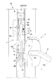
図1〜図4に示すように、窓用ロック装置1は、右縦枠22Sの屋内側に取り付けられた基体1A、基体1Aにより支持されて左右方向の支軸2Aまわりに揺動するロック操作部材2、屋外方向へ突出してロック操作部材2の揺動に伴って揺動する連結片2B、右縦枠22Sに沿って上下方向に移動可能に支持され、連結片2Bにより操作されて上下方向に移動する連動部材3、連動部材3に取り付けられた鈎状掛止片7、障子23の開放側縁部(開閉端である右縦框23S(戸先框))に取り付けられて鈎状掛止片7により掛止される掛止ピン19等により構成される。
ここで、図1〜図3及び図6(a)に示すように、上下方向に延びる略矩形板状の連動部材3には、その上下端に合成樹脂製のガイド体4,5が取り付けられ、上下のガイド体4,5が、図4に示す右縦枠22Sに形成したガイド溝20に係合するため、連動部材3は、ガイド溝20にガイドされながら右縦枠22Sに沿って上下方向に移動可能に支持される。
As shown in FIGS. 1 to 4, the window locking device 1 includes a
Here, as shown in FIG. 1 to FIG. 3 and FIG. 6A, synthetic
また、連動部材3下端の下ガイド体5には左方に突出する連動ピン6が取り付けられ、連動ピン6は連結片2Bのロック操作用長孔2Cに挿通されるため、図2及び図3に示すようにロック操作部材2の操作による支軸2Aまわりの連結片2Bの揺動に連動して連動部材3は上下方向に移動する。
さらに、図6(b)に示すように、鈎状掛止片7は連動部材3の上下方向中間位置(上下のガイド体4,5の間)に取り付けられた取付部7A、取付部7Aから左方(取付部7Aから離間する方向)へ延びる連結部7B、連結部7Bの自由端縁に繋がって上方(窓枠に沿う方向)へ延びる掛止部7Cからなる。
Also, the
Further, as shown in FIG. 6 (b), the hook-shaped
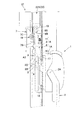
さらにまた、窓用ロック装置1は、誤ロック防止装置Aを備えており、誤ロック防止装置Aは、図5及び図6(a)に示すように、右縦枠22Sに取り付けられる取付部材8、取付部材8により前後方向へ揺動可能に支持されたトリガー9、トリガーを前方へ付勢する弾性付勢手段である圧縮コイルばね11を備えている。
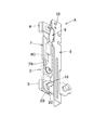
図6(a)に示すように、取付部材8は上下方向に長い平面視略アングル状であり、段付シャフト10を右方からトリガー9上端部(基端部)の通孔9A及び取付部材8上端部の通孔8Aに挿通して軸端をかしめることにより、トリガー9下端部(遊端部)が前後方向へ揺動可能なように取付部材8にトリガー9が取り付けられ、取付部材8に突設された係合凸部8Bがトリガー9の通孔9A下方の前後長孔9Bに係合するため、取付部材8に対するトリガー9の揺動角度範囲が制限される。
Furthermore, the window lock device 1 includes an erroneous lock prevention device A, and the erroneous lock prevention device A is attached to the right
As shown in FIG. 6A, the mounting
また、図5及び図6(a)に示すように、取付部材8とトリガー9との間には、取付部材8のばね支持凸部13及びトリガー9のばね支持凸部14がコイル両端部に挿入された圧縮コイルばね11が介在しているため、トリガー9は前方へ弾性付勢されており、図1、図4、図5(b)及び図7に示す障子23の開状態では、トリガー9の下端部(遊端部)である当止部9Cが鈎状掛止片7の連結部7Bの真上に位置している。
ここで、誤ロック防止装置Aは、取付部材8にトリガー9及び圧縮コイルばね11を取り付けて図5に示すようにユニット化されているため、図8に示す窓用ロック装置1のロック操作部材2を支持して右縦枠22Sに取り付けられる基体1Aの上下の取付ねじ17,18を共用し、図5(a)に示す取付部材8の切欠15及び通孔16を利用して図1に示すように右縦枠22Sに容易に取り付けることができる。
Further, as shown in FIGS. 5 and 6A, between the
Here, since the erroneous lock prevention device A is unitized as shown in FIG. 5 by attaching the
次に、誤ロック防止装置A及び窓用ロック装置1の動作について説明する。
図1に示す障子23の開状態では、上述のとおりトリガー9の当止部9Cが鈎状掛止片7の連結部7Bの真上に位置していることから、窓用ロック装置1のロック操作部材2を下方へ操作しようした際に、当止部9Cにより連結部7Bが当止されてロック操作部材2の操作に連動する連動部材3の上方への移動が阻止され、ロック操作部材2は操作不能となるため、誤操作が防止される。
この障子23の開状態から、図示しないオペレーターにより障子23を閉じる方向へ移動させて障子23開放側縁部の掛止ピン19が図1中の矢印A1のように窓枠22に近づき、図2のように掛止ピン19がトリガー9を圧縮コイルばね11の付勢力に抗して揺動させた障子23の閉状態では、トリガー9が連結部7Bの真上から後方へ移動してトリガー9の連結部8Bへの当止が解除される。
したがって、ロック操作部材2は図2中の矢印A2のように操作可能となり、図3のようにロック操作部材2を下方へ操作した状態では、図3中の矢印A3のように連動部材3とともに鈎状掛止片7が上方へ移動して掛止ピン19を掛止するため、窓用ロック装置1により障子23は窓枠22に対して施錠される。
Next, operations of the erroneous lock prevention device A and the window lock device 1 will be described.
In the open state of the
From the open state of the
Therefore, the
以上のような構成の誤ロック防止装置Aによれば、誤ロック防止装置Aが、取付部材8、トリガー9及び圧縮コイルばね11からなる簡素な構成であるため、製造コストを低減することができるとともに、揺動するトリガー9の当止部9Cが鈎状掛止片7の連結部7Bを当止する構成であるため、これらの部品の強度や精度を向上することが容易である。
また、窓枠22にトリガー受けを取り付ける必要がないため、窓枠22にトリガー受けを取り付けるスペースがない場合であっても使用することができる。
さらに、窓枠22に取り付けられる取付部材8にトリガー9及び圧縮コイルばね11を取り付けてユニット化されているため、このようにユニット化された誤ロック防止装置Aを、誤ロック防止装置Aを備えていない既設の窓用ロック装置1(例えば図8参照。)に対して既設部品を取り外すことなく後付けで取り付けることができる。
さらにまた、窓用ロック装置1の基体1Aの取付ねじ17,18を共用して取り付けることができるため、誤ロック防止装置Aを備えていない既設の窓用ロック装置1に対して、現場合わせで窓枠22にねじ穴を加工することなく後付けで容易に取り付けることができる。
According to the erroneous lock prevention device A having the above-described configuration, the erroneous lock prevention device A has a simple configuration including the
Moreover, since it is not necessary to attach a trigger receptacle to the
Further, since the
Furthermore, since the mounting
以上の説明においては、窓21が縦すべり出し窓である場合について説明したが、窓21は、横すべり出し窓、片開き窓又は突出し窓等であってもよく、窓21が例えば横すべりだし窓である場合には、連動部材3を、窓枠22の下枠に沿って左右方向に移動可能に支持し、基体1A、ロック操作部材2及び連結片2Bを上下方向の支軸まわりに揺動するように下枠に取り付け、誤ロック防止装置Aを下枠に取り付け、掛止ピン19を障子23の戸先框である下框に取り付ければよい。
In the above description, the case where the
A 誤ロック防止装置
1 窓用ロック装置
1A 基体
2 ロック操作部材
2A 支軸
2B 連結片
2C ロック操作用長孔
3 連動部材
4,5 ガイド体
6 連動ピン
7 鈎状掛止片
7A 取付部
7B 連結部
7C 掛止部
8 取付部材
8A 通孔
8B 係合凸部
9 トリガー
9A 通孔
9B 前後長孔
9C 当止部
10 段付シャフト
11 圧縮コイルばね(弾性付勢手段)
13,14 ばね支持凸部
15 切欠
16 通孔
17,18 取付ねじ
19 掛止ピン
20 ガイド溝
21 窓
22 窓枠
22S 縦枠
23 障子
23S 縦框
A Accidental lock prevention device 1
13, 14 Spring support
Claims (3)
前記窓枠に取り付けられる取付部材と、
該取付部材により室内外方向へ揺動可能に支持されたトリガーと、
該トリガーを室外方向へ付勢する弾性付勢手段とを備え、
前記障子の開状態では前記トリガーが前記鈎状掛止片の連結部を当止して前記連動部材の移動が阻止されるため前記ロック操作部材は操作不能となり、
前記障子を閉じることにより前記掛止ピンが前記トリガーを前記弾性付勢手段の付勢力に抗して揺動させて前記トリガーの前記連結部への当止が解除されるため前記ロック操作部材は操作可能となることを特徴とする誤ロック防止装置。 In a window that can open and close the shoji built in the window frame in the indoor and outdoor direction, an attachment part attached to an interlocking member that is operated and moved by a lock operation member on the indoor side, in a direction away from the attachment part A hook-like hooking piece comprising a connecting part extending and a hooking part connected to the free end edge of the connecting part and extending in the direction along the window frame is hooked to a hooking pin attached to an opening side edge of the shoji. A locking device for locking used for locking the window, and an erroneous locking prevention device for preventing erroneous operation of the locking device for windows in the open state of the shoji,
An attachment member attached to the window frame;
A trigger supported by the mounting member so as to be swingable indoors and outdoors;
Elastic biasing means for biasing the trigger in the outdoor direction,
In the open state of the shoji, the trigger stops the connecting portion of the hook-shaped latching piece and the movement of the interlocking member is prevented, so that the lock operation member becomes inoperable,
By closing the shoji, the latching pin swings the trigger against the urging force of the elastic urging means so that the engagement of the trigger with the connecting portion is released. An erroneous lock prevention device characterized by being operable.
A window lock device comprising the false lock prevention device according to claim 1.
Priority Applications (1)
| Application Number | Priority Date | Filing Date | Title |
|---|---|---|---|
| JP2011065447A JP5609733B2 (en) | 2011-03-24 | 2011-03-24 | False lock prevention device and window lock device provided with the same |
Applications Claiming Priority (1)
| Application Number | Priority Date | Filing Date | Title |
|---|---|---|---|
| JP2011065447A JP5609733B2 (en) | 2011-03-24 | 2011-03-24 | False lock prevention device and window lock device provided with the same |
Publications (2)
| Publication Number | Publication Date |
|---|---|
| JP2012202044A true JP2012202044A (en) | 2012-10-22 |
| JP5609733B2 JP5609733B2 (en) | 2014-10-22 |
Family
ID=47183339
Family Applications (1)
| Application Number | Title | Priority Date | Filing Date |
|---|---|---|---|
| JP2011065447A Active JP5609733B2 (en) | 2011-03-24 | 2011-03-24 | False lock prevention device and window lock device provided with the same |
Country Status (1)
| Country | Link |
|---|---|
| JP (1) | JP5609733B2 (en) |
Cited By (1)
| Publication number | Priority date | Publication date | Assignee | Title |
|---|---|---|---|---|
| JP6977976B1 (en) * | 2021-01-28 | 2021-12-08 | アルメタックス株式会社 | Window opening / closing lock device |
Citations (2)
| Publication number | Priority date | Publication date | Assignee | Title |
|---|---|---|---|---|
| JP2007247357A (en) * | 2006-03-20 | 2007-09-27 | Nakanishi Eng:Kk | Fastener fitting and window sash using this fitting |
| JP4337068B2 (en) * | 1999-09-14 | 2009-09-30 | 美和ロック株式会社 | Window lock device |
-
2011
- 2011-03-24 JP JP2011065447A patent/JP5609733B2/en active Active
Patent Citations (2)
| Publication number | Priority date | Publication date | Assignee | Title |
|---|---|---|---|---|
| JP4337068B2 (en) * | 1999-09-14 | 2009-09-30 | 美和ロック株式会社 | Window lock device |
| JP2007247357A (en) * | 2006-03-20 | 2007-09-27 | Nakanishi Eng:Kk | Fastener fitting and window sash using this fitting |
Cited By (1)
| Publication number | Priority date | Publication date | Assignee | Title |
|---|---|---|---|---|
| JP6977976B1 (en) * | 2021-01-28 | 2021-12-08 | アルメタックス株式会社 | Window opening / closing lock device |
Also Published As
| Publication number | Publication date |
|---|---|
| JP5609733B2 (en) | 2014-10-22 |
Similar Documents
| Publication | Publication Date | Title |
|---|---|---|
| US20210404228A1 (en) | Sash window restrictor | |
| US9752355B2 (en) | Vehicle door latch device | |
| JP2007020922A (en) | Locking device of game machine | |
| PL1963602T3 (en) | A noise reducing locking assembly for a ventilating window | |
| JP5609733B2 (en) | False lock prevention device and window lock device provided with the same | |
| JP4911021B2 (en) | Opening device | |
| JP5141372B2 (en) | Window lock device | |
| US8403381B2 (en) | Horse stall door latch | |
| JP2021080643A (en) | Window opening and closing lock apparatus | |
| JP4516877B2 (en) | Key conversion type lock | |
| JP2022115658A (en) | Window open/close locking device | |
| KR101990693B1 (en) | Locking device for screens preventing crimees and insections | |
| JP2834115B1 (en) | Automatic locking type lock device | |
| JP4221136B2 (en) | Strike of sliding door sickle lock | |
| WO2020000041A1 (en) | An electric strike assembly | |
| KR101990692B1 (en) | Locking device for screens preventing crimees and insections | |
| JP7460992B1 (en) | Window locking device, window sash and wall structure | |
| JP4785555B2 (en) | Dead metal bracket | |
| JP2012001977A (en) | Locking device for double-hung window | |
| JP2011153470A (en) | Door tightening device and door | |
| JP4953958B2 (en) | Game machine locking device | |
| JP2007224671A (en) | Bracket for dead bolt | |
| EP1749960A1 (en) | Sliding and privoting assembly and release/closure mechanism threrefor | |
| JP2006022515A (en) | Operation error preventing device of sash locking mechanism | |
| JP5120794B2 (en) | Door lock deadbolt with built-in sickle mechanism and sickle drive guide mechanism |
Legal Events
| Date | Code | Title | Description |
|---|---|---|---|
| A621 | Written request for application examination |
Free format text: JAPANESE INTERMEDIATE CODE: A621 Effective date: 20131227 |
|
| A977 | Report on retrieval |
Free format text: JAPANESE INTERMEDIATE CODE: A971007 Effective date: 20140731 |
|
| TRDD | Decision of grant or rejection written | ||
| A01 | Written decision to grant a patent or to grant a registration (utility model) |
Free format text: JAPANESE INTERMEDIATE CODE: A01 Effective date: 20140805 |
|
| A61 | First payment of annual fees (during grant procedure) |
Free format text: JAPANESE INTERMEDIATE CODE: A61 Effective date: 20140818 |
|
| R150 | Certificate of patent or registration of utility model |
Ref document number: 5609733 Country of ref document: JP Free format text: JAPANESE INTERMEDIATE CODE: R150 |
|
| R250 | Receipt of annual fees |
Free format text: JAPANESE INTERMEDIATE CODE: R250 |
|
| R250 | Receipt of annual fees |
Free format text: JAPANESE INTERMEDIATE CODE: R250 |
|
| R250 | Receipt of annual fees |
Free format text: JAPANESE INTERMEDIATE CODE: R250 |
|
| R250 | Receipt of annual fees |
Free format text: JAPANESE INTERMEDIATE CODE: R250 |
|
| R250 | Receipt of annual fees |
Free format text: JAPANESE INTERMEDIATE CODE: R250 |
|
| R250 | Receipt of annual fees |
Free format text: JAPANESE INTERMEDIATE CODE: R250 |
|
| R250 | Receipt of annual fees |
Free format text: JAPANESE INTERMEDIATE CODE: R250 |