JP2012201166A - Large dump truck - Google Patents
Large dump truck Download PDFInfo
- Publication number
- JP2012201166A JP2012201166A JP2011066086A JP2011066086A JP2012201166A JP 2012201166 A JP2012201166 A JP 2012201166A JP 2011066086 A JP2011066086 A JP 2011066086A JP 2011066086 A JP2011066086 A JP 2011066086A JP 2012201166 A JP2012201166 A JP 2012201166A
- Authority
- JP
- Japan
- Prior art keywords
- driver
- dump truck
- vehicle width
- width direction
- surface portion
- Prior art date
- Legal status (The legal status is an assumption and is not a legal conclusion. Google has not performed a legal analysis and makes no representation as to the accuracy of the status listed.)
- Withdrawn
Links
Images
Landscapes
- Fittings On The Vehicle Exterior For Carrying Loads, And Devices For Holding Or Mounting Articles (AREA)
Abstract
【課題】運転者の顔画像を明瞭に撮影でき、かつ各種装置の車両への組立作業を容易にできる大型ダンプトラックを提供すること。
【解決手段】大型ダンプトラックにおいて、キャブ内には、ハンドルより前方で、かつ該ハンドルの回転中心よりも車幅方向の他方側に寄せて配置される赤外線カメラ21と、ハンドルの回転中心に対して車幅方向の両側に配置される一対の赤外線ランプ22,23と、これらを支持する支持フレーム10と、ダッシュボード6内に収容されたモニタフレーム63とが設けられ、支持フレーム10は、モニタフレーム63に固定される中央部10A、中央部10Cから車幅方向の一方側に延出した第1アーム部10B、中央部10Aから車幅方向の他方側に延出した第2アーム部10Cで形成され、第1、第2アーム部10B,10Cは、赤外線カメラ21および赤外線ランプ22,23が取り付けられる天面部121,131と、天面部121,131に一体でかつ車幅方向に沿った垂下部122,132とを有している。
【選択図】図4To provide a large dump truck that can clearly photograph a driver's face image and can easily assemble various devices into a vehicle.
In a large dump truck, an infrared camera 21 disposed in the cab in front of the handle and closer to the other side in the vehicle width direction than the rotation center of the handle, and the rotation center of the handle A pair of infrared lamps 22 and 23 arranged on both sides in the vehicle width direction, a support frame 10 that supports them, and a monitor frame 63 accommodated in the dashboard 6 are provided. A central portion 10A fixed to the frame 63, a first arm portion 10B extending from the central portion 10C to one side in the vehicle width direction, and a second arm portion 10C extending from the central portion 10A to the other side in the vehicle width direction. The first and second arm portions 10B and 10C are formed with top surface portions 121 and 131 to which the infrared camera 21 and the infrared lamps 22 and 23 are attached, and the top surface portion 1. And a hanging portion 122, 132 along the and vehicle width direction integrally with the 1,131.
[Selection] Figure 4
Description
本発明は、大型ダンプトラックに係り、例えば鉱山等で使用される大型ダンプトラックに関する。 The present invention relates to a large dump truck, for example, a large dump truck used in a mine or the like.
従来、トラックやバスなどの運転室内において、運転者の顔画像を撮影するためのカメラ装置が知られている(例えば、特許文献1参照)。トラックやバスの運転者は、座席に着座した姿勢のまま正面を向いて運転することから、カメラ装置は、運転席およびハンドルの前方であって、運転者の正面に配置され、カメラ装置で撮影された顔画像から、例えばまばたき具合を判断し、運転者が居眠りしつつあることが検知される。 2. Description of the Related Art Conventionally, a camera device for capturing a driver's face image in a driver's room such as a truck or a bus is known (see, for example, Patent Document 1). Since the driver of the truck or bus faces the front while sitting on the seat, the camera device is placed in front of the driver's seat and steering wheel and in front of the driver, and is photographed by the camera device. From the face image thus obtained, for example, the degree of blinking is determined, and it is detected that the driver is falling asleep.
ところで、作業車両としての鉱山作業用の大型ダンプトラックでは、その車幅が特許文献1等で想定している車両の車幅よりも格段に大きく、車高も格段に高い。近年では、このような大型ダンプトラックにおいても、キャブ内で操縦する運転者の居眠りを防止する装置が設けられることがある。 By the way, in a large dump truck for mining work as a work vehicle, the vehicle width is much larger than the vehicle width assumed in Patent Document 1 and the like, and the vehicle height is also significantly higher. In recent years, even in such a large dump truck, there is a case in which a device for preventing a driver navigating in a cab is provided.
しかし、大型ダンプトラックの運転者を従来のようなカメラ装置を用いて撮影したのでは、顔画像を正確に撮像できず、居眠り検知の信頼性が低下するという問題がある。これは、従来のトラックやバスは、一般道を走行する車両であり、鉱山等で使用される大型ダンプトラックと比較すると小型車両に過ぎないため、大型ダンプトラックに特有な運転状況が全く考慮されていないことによると考えられる。 However, if a driver of a large dump truck is photographed using a conventional camera device, a face image cannot be accurately captured, and there is a problem that the reliability of dozing detection is reduced. This is because conventional trucks and buses are vehicles that travel on ordinary roads, and are only small vehicles compared to large dump trucks used in mines, etc., so the driving conditions specific to large dump trucks are completely considered. It is thought that it is not.
本発明の目的は、運転者の顔画像を明瞭に撮影でき、かつ各種装置の車両への組立作業を容易にできる大型ダンプトラックを提供することである。 An object of the present invention is to provide a large-sized dump truck that can clearly capture a driver's face image and can easily assemble various devices into a vehicle.
第1発明に係る大型ダンプトラックは、ボディと、前記ボディの前方上部であって、車幅方向の一方側に寄って載置されたキャブと、前記ボディの後方上部に載置されたベッセルとを備えた大型ダンプトラックにおいて、前記キャブ内には、運転者が前方を向いて着座する運転席と、運転席の正面位置で回転操作されるハンドルと、前記ハンドルの前方に設けられたダッシュボードと、前記ハンドルより前方で、かつ該ハンドルの回転中心よりも車幅方向の他方側に寄せて配置される撮像装置と、前記ハンドルの回転中心に対して車幅方向の両側に配置される少なくとも一対の照明装置と、前記撮像装置および前記照明装置を支持する支持フレームと、前記ダッシュボード内に収容されたモニタフレームとが設けられ、前記支持フレームは、前記モニタフレームに固定される中央部、前記中央部から車幅方向の一方側に延出した第1アーム部、前記中央部から車幅方向の他方側に延出した第2アーム部で形成され、前記第1、第2アーム部は、前記撮像装置および前記照明装置のうちの少なくとも前記照明装置が取り付けられる天面部と、前記天面部に一体でかつ車幅方向に沿った垂下部とを有していることを特徴とする。 A large-sized dump truck according to a first aspect of the present invention is a body, a cab that is placed on one side in the vehicle width direction at the front upper part of the body, and a vessel that is placed on the rear upper part of the body. In the large dump truck provided with the above, in the cab, a driver seat on which a driver is seated facing forward, a handle that is rotated at a front position of the driver seat, and a dashboard provided in front of the handle An imaging device disposed in front of the handle and closer to the other side in the vehicle width direction than the rotation center of the handle, and at least disposed on both sides in the vehicle width direction with respect to the rotation center of the handle A pair of illumination devices, a support frame that supports the imaging device and the illumination device, and a monitor frame housed in the dashboard are provided, the support frame is A central portion fixed to the monitor frame, a first arm portion extending from the central portion to one side in the vehicle width direction, and a second arm portion extending from the central portion to the other side in the vehicle width direction. The first and second arm portions each include a top surface portion to which at least the illumination device of the imaging device and the illumination device is attached, and a hanging portion that is integral with the top surface portion and extends in the vehicle width direction. It is characterized by that.
第2発明に係る大型ダンプトラックでは、前記第1、第2アーム部は、前記天面部と対向した底面部と、前記底面部に一体でかつ車幅方向に沿った立上部とをさらに有していることを特徴とする。 In the large dump truck according to the second aspect of the present invention, the first and second arm portions further include a bottom surface portion facing the top surface portion, and an upright portion integrated with the bottom surface portion and along the vehicle width direction. It is characterized by.
第3発明に係る大型ダンプトラックでは、前記支持フレームは、前記第1、第2アーム部に対応した前記底面部および前記立上部を有するベースフレームと、前記第1アーム部に対応した前記前記天面部および前記垂下部を有する第1カバーと、前記第2アーム部に対応した前記前記天面部および前記垂下部を有する第2カバーとを備え、前記第1、第2カバーが前記ベースフレームに取り付けられることを特徴とする。 In the large dump truck according to a third aspect of the present invention, the support frame includes a base frame having the bottom surface portion and the upright portion corresponding to the first and second arm portions, and the ceiling corresponding to the first arm portion. A first cover having a surface portion and the hanging portion; and a second cover having the top surface portion and the hanging portion corresponding to the second arm portion, wherein the first and second covers are attached to the base frame. It is characterized by being able to.
第4発明に係る大型ダンプトラックでは、前記支持フレームは、前記ベースフレームの前記中央部に対応した位置で箱状の固定ボックスを介して前記モニタフレームに固定されることを特徴とする。 In the large dump truck according to a fourth aspect of the present invention, the support frame is fixed to the monitor frame via a box-shaped fixed box at a position corresponding to the central portion of the base frame.
第5発明に係る大型ダンプトラックでは、前記支持フレームは、平面視にて前記運転席側に拡開した弓形状であることを特徴とする。 In the large dump truck according to a fifth aspect of the invention, the support frame has a bow shape that is widened toward the driver's seat in a plan view.
図8に示すように、車幅が格段に大きい大型ダンプトラック1では、運転席が設けられているキャブ3は、車幅方向の車幅中心Cに対して一方側、すなわち対面通行での路肩S側に大きく寄せて配置されている。これは、センターラインが存在しない鉱山道を大型ダンプトラック1で走行する場合、大きな車幅であっても路肩Sとの距離L1を容易に確認できるようにするためであり、路肩との距離L1を確認しながら走行することで、車幅が大きい大型ダンプトラック1同士のすれ違い時の距離L2を確実に確保するとともに、十分に整備されていない路肩Sの岩や盛土に車体が接触するのを防止しているのである。
As shown in FIG. 8, in the large dump truck 1 having a significantly large vehicle width, the
そのような大型ダンプトラック1では、キャブ3が路肩S側に大きく寄せて配置されているため、大型ダンプトラック1における運転者の位置と、一般道路を走行するトラックやバスにおける運転者の位置とは大きく異なる。この結果、大型ダンプトラック1の運転者の視線は、路肩S側から仮想的なセンターラインCL(図8)側に向けられることになり、車幅の大きな大型ダンプトラック1が走行する鉱山道の道幅は、やはり一般道とは比較にならないほど大きいことから、視線を維持するために運転者は、顔の向きそのものを正面に対してセンターラインCL側に向けておくことになる。
In such a large dump truck 1, the
このように、大型ダンプトラック1での特有な状況を鋭意調査した結果、本発明の発明者等によれば、大型ダンプトラック1を運転中の運転者の顔は、着座位置に対して正面を向いていないことが多く、顔の向きによっては目元付近に影ができてしまうため、運転者の顔画像を撮影するカメラ装置だけでは、運転者の顔画像を明瞭に撮影できず、運転者の居眠り検知の信頼性が低下することを突き止めた。 As described above, as a result of earnest investigation of the unique situation in the large dump truck 1, according to the inventors of the present invention, the face of the driver who is driving the large dump truck 1 is in front of the seating position. Because it is often not suitable and a shadow is created near the eyes depending on the orientation of the face, only the camera device that shoots the driver's face image cannot clearly shoot the driver's face image. We found out that the reliability of dozing detection declines.
つまり、車幅が格段に大きい大型ダンプトラック1のように、キャブ3が車幅方向の一方側である例えば路肩S側に大きく寄せて配置されている場合、また、そのような大型ダンプトラック1で道幅の大きな道路を走行する場合にあっては、キャブ3内の運転者の姿勢そのものは正面を向いているが、運転者の顔としては正面ではなく、通行する道路のセンターラインCL(実際にセンターラインが存在するか否かは不問)側、すなわち車幅方向の他方側を向く傾向がある。また、路肩との距離L1に注意する必要性から、車幅方向の他方側についても、頻繁に向くことになる。この際、いずれを向いた場合でも、目元に影が生じないことが望まれるが、1つの照明装置だけでは、両方の向きで影ができないようにすることは困難である。
That is, in the case where the
また、大型ダンプトラックの走行路は、舗装されておらず、路面のうねりにより撮像装置や照明装置にも揺れが生じるが、特許文献1に記載されているように、撮像装置および照明装置を支柱部分の長い支持器具の先端に取り付けたのでは、そのような揺れを容易に減衰できず、従って、この点でも運転者の顔画像を鮮明に撮影することができなくて、居眠り検知の信頼性が低下することが判った。
さらに、撮像装置および照明装置をダッシュボード等に個別に取り付けたのでは、取付作業に手間がかかり、作業が繁雑になることも判った。
Further, the traveling path of the large dump truck is not paved, and the imaging device and the lighting device are shaken due to the road surface undulations. If it is attached to the tip of a long support device, such shaking cannot be attenuated easily. Therefore, the driver's face image cannot be taken clearly at this point, and the reliability of detection of doze Was found to be reduced.
Furthermore, it has been found that if the imaging device and the lighting device are individually attached to a dashboard or the like, the installation work is troublesome and the work becomes complicated.
以上の知見に基づき、第1発明では、少なくとも2つの照明装置を運転者の正面にあるハンドルの回転中心に対して、車幅方向の両側に配置するので、運転者の顔が走路のセンターラインよりを向いていても、あるいは路肩側を向いていても、運転者の顔を良好に照らすことができる。
しかも、撮像装置および2つの照明装置を、ダッシュボードなどに個別に固定するのではなく、また、従来のような支柱部分の長い支持器具に取り付ける訳でもない。つまり、第1発明では、車幅方向に長い第1、第2アーム部を有した支持フレームの両端側に照明装置を取り付け、この支持フレームをダッシュボードの内部に収容されているモニタフレームに固定するので、固定構造を堅固にできる。そして、第1、第2アーム部は、撮像装置や照明装置が取り付けられる天面部の他、名車幅方向に沿った垂下部を有することで、剛性を向上させることができる。
さらに、撮像装置および照明装置を予め外段取りで支持フレームに取り付けておくことで、キャブ内においては、そのような支持フレームをモニタフレームに取り付けるだけでよいから、撮像装置および照明装置をキャブ内で個別に取り付ける必要がなく、組立性を良好にできる。
以上のことから、顔の向きに係わらず、影を生じ難くできるうえ、悪路を走行しても揺れが生じ難くいから、顔画像の撮影を明瞭にできて、居眠り検知等の信頼性を向上させることができ、また、組立作業も容易にできる。
Based on the above knowledge, in the first invention, since at least two lighting devices are arranged on both sides in the vehicle width direction with respect to the rotation center of the steering wheel in front of the driver, the driver's face is the center line of the runway. The driver's face can be well illuminated even if he is facing more or facing the shoulder.
In addition, the imaging device and the two illumination devices are not individually fixed to a dashboard or the like, nor are they attached to a conventional support device having a long column portion. In other words, in the first aspect of the invention, the lighting device is attached to both ends of the support frame having the first and second arm portions that are long in the vehicle width direction, and the support frame is fixed to the monitor frame housed inside the dashboard. Therefore, the fixing structure can be made firm. And the 1st and 2nd arm part can improve rigidity by having a hanging part along the famous vehicle width direction in addition to the top surface part to which an imaging device and an illuminating device are attached.
Furthermore, by attaching the imaging device and the illumination device to the support frame by external setup in advance, it is only necessary to attach such a support frame to the monitor frame in the cab. There is no need to install them individually, and the assemblability can be improved.
From the above, regardless of the orientation of the face, it is difficult to produce shadows, and it is difficult to shake even when driving on rough roads, so it is possible to clearly capture face images and improve reliability such as detection of doze In addition, the assembly work can be facilitated.
第2発明によれば、天面部および立上部を有することで、第1、第2アーム部を中空の箱状にできて、その断面形状を閉断面とすることができ、第1、第2アーム部の剛性をさらに向上させることができる。 According to the second invention, the first and second arm portions can be formed into a hollow box shape by having the top surface portion and the upright portion, and the cross-sectional shape thereof can be a closed cross section. The rigidity of the arm portion can be further improved.
第3発明によれば、閉断面を有した中空箱状の第1、第2アーム部を、ベースフレームと第1、第2カバーとで構成するので、撮像装置や照明装置のケーブルなどは、ベースフレーム内に収容させて、これを覆う第1、第2カバーにて隠れることになるから、ケーブルの収容を容易にできるとともに、ケーブルが外部にはみ出すことがなく、外観上の意匠性を向上させることができる。 According to the third aspect of the invention, the hollow box-shaped first and second arm portions having a closed cross section are constituted by the base frame and the first and second covers. Since it is housed in the base frame and hidden by the first and second covers that cover it, the cable can be easily housed and the cable does not protrude outside, improving the appearance design. Can be made.
第4発明によれば、支持フレームはダッシュボードに設けられた接地用の開口部分を通してモニタフレームに固定されることになるが、この際に固定ボックスを介して固定することで、ダッシュボード分の厚みによる段差を固定ボックスで埋めることができ、支持フレームをそのような段差で邪魔されることなしに、安定した状態でダッシュボードの上方に確実に位置させることができる。 According to the fourth invention, the support frame is fixed to the monitor frame through the opening portion for grounding provided in the dashboard. At this time, by fixing the support frame via the fixing box, The step due to the thickness can be filled with a fixed box, and the support frame can be reliably positioned above the dashboard without being disturbed by such a step.
第5発明によれば、支持フレームが弓形(V字形状)であるから、撮像装置や照明装置だけではなく、支持フレーム全体が運転者側に向いているような印象を与えることができ、居眠り状態が監視されていることを運転者により強く意識させることができて、居眠りの抑止効果を向上させることができる。
また、支持フレームの運転者との対向面に、LED等を点灯表示させるようした警告装置を設ける場合など、運転者側からのLEDの視認性を向上させることができる。
According to the fifth aspect of the present invention, since the support frame is bow-shaped (V-shaped), it is possible to give an impression that the entire support frame is facing the driver side, not just the imaging device and the lighting device, and doze The driver can be made more aware that the condition is being monitored, and the effect of suppressing the dozing can be improved.
Further, the visibility of the LED from the driver side can be improved, for example, when a warning device is provided on the surface of the support frame facing the driver so that the LED or the like is turned on.
以下、本発明の一実施形態を図面に基づいて説明する。
なお、以下の説明において、前後左右方向とは、運転者が図2に示す運転席301に着座した状態における前後左右方向と同一方向をいう。また、左右方向と車幅方向とは同義である。
Hereinafter, an embodiment of the present invention will be described with reference to the drawings.
In the following description, the front / rear / left / right direction refers to the same direction as the front / rear / left / right direction when the driver is seated on the driver's
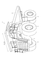
図1に示す大型ダンプトラック1は、フレーム構造を有したボディ2を備え、ボディ2の前方上部にはキャブ3が搭載され、ボディ2の後方上部には、例えば採掘された岩石や土砂等の積載物を積載するベッセル4が設けられている。
ボディ2には、前後左右に4つの走行輪5が取り付けられている。走行輪5は、図示しない駆動源からの駆動力によって駆動される。
ボディ2の前面には、高所に配置されたキャブ3と地上との間で昇降を行うためのラダー7が左右に設けられている。また、ボディ2の上部おいて、キャブ3回りに設けられた歩行可能エリア等には手摺8が取り付けられ、車幅方向(車両の左右方向)の両端に対応した位置の手摺8にはサイドミラー9が取り付けられている。
A large dump truck 1 shown in FIG. 1 includes a body 2 having a frame structure, and a
Four traveling
On the front surface of the body 2, ladders 7 are provided on the left and right for moving up and down between the
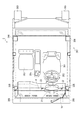
キャブ3は、ボディ2の前方上部であって、車幅方向の左端側に寄せて載置され、その内部には、図2に示すように、運転者が着座する運転席301が左側に配置され、運転席301の右側には補助席303が並んで配置されている。つまり、大型ダンプトラック1では、車幅方向の左寄りに寄せられたキャブ3の内部においても、さらに左寄りに運転席301が配置されている。このようは配置により、対面通行時に左車線を走ることになる本実施形態の大型ダンプトラック1では、運転者は左側の路肩を確実に確認でき、確認しながらの走行を容易にできる。キャブ3内には、運転席301の前方正面にハンドル302が配置され、運転席301と補助席303との間にベッセル4の傾倒操作を行うベッセルレバー304が設けられている。
The
また、本実施形態のキャブ3では、前側の左右一対の支柱フレーム305、および後側の左右一対の支柱フレーム306を有したROPS(Roll Over Protective Structure)フレーム307が採用されている。さらにキャブ3は、下面前側に設けられた左右一対のキャブマウント308、および背面下部側に設けられた左右一対のキャブマウント309を介してボディ2のフレームに搭載されている。
Further, in the
ベッセル4は、図示しないホイストシリンダを介してボディ2の後方上部に載置され、ホイストシリンダを伸縮させることにより、下側を回動中心として、ボディ2に対して回動可能に取り付けられている。
The
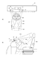
図3、図4に示すように、キャブ3内において、ハンドル302の前方にはダッシュボード6が設けられ、そのダッシュボード6の上側は合成樹脂のダッシュカバー61で構成されている。ダッシュカバー61には、撮像装置としての赤外線カメラ21、照明装置としての2つの赤外線ランプ22,23、および車幅方向に沿った所定長さを有してそれらを支持する支持フレーム10が設置されている。
As shown in FIGS. 3 and 4, in the
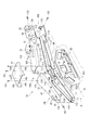
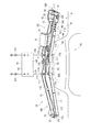
先ず、支持フレーム10は、運転者の視界を妨げない程度に薄型で箱形状であり、平面視にて運転席301側に向かって弓状(略V字形状)に拡開した形状を有している。つまり、支持フレーム10は、後述のモニタフレーム63に固定される中央部10A、中央部10Aから車幅方向の一方側に延出した第1アーム部10B、他方側に延出した第2アーム部10C、および第2アーム部10Cの先端に設けられたスイッチ収容部10Dからなる。
First, the
また、支持フレーム10を構成する部材としては、各々金属プレートで形成されたベースフレーム11、第1カバー12、第3カバー13、センターカバー14、および固定ボックス15が用いられている。ベースフレーム11は、支持フレーム10の中央部10A、第1、第2アーム部10C、10C、およびスイッチ収容部10Dの各下側部分を形成している。第1カバー12は、第1アーム部10Bの上側部分を形成している。第2カバー13は、第2アーム部10Cおよびスイッチ収容部10Dの上側部分を形成している。また、センターカバー14は、中央部10Aの上側部分を形成している。固定ボックス15は、平面四角形で有底箱状とされ、中央部10Aにおいて、ベースフレーム11の下面に固着されたている。
As the members constituting the
具体的に説明すると、支持フレーム10は、各種メータやコーションランプ類で構成されるメインモニタ62と共に、やはり金属プレート製のモニタフレーム63に水平に固定されている。モニタフレーム63は、詳細には後述するが、メインモニタ62が取り付けられた状態で、ダッシュカバー61に形成された山状部64で覆われている。山状部64は、ダッシュカバー61上において、上方に盛り上がった部分である。山状部64の表面部分の曲面形状等は、ハンドル302の径寸法や意匠性などを考慮して決められる。
More specifically, the
ベースフレーム11は、弓状の底面部111、および底面部111の外周に沿って立設された立上部112にて形成されている。十分な板厚の金属プレートを用いること、および底面部111と立上部112とで断面形状がチャンネル形状になっていることにより、所定長さを有したベースフレーム11の剛性が十分に確保され、長さ方向の途中で自重により撓んだり、振動によって両端側が上下に振れたりすることはない。
The
ベースフレーム11の立上部112において、運転席301に向いた位置で、かつスイッチ収容部10Dに近接した位置には、切欠部114が設けられている。切欠部114に対応した底面部111上には、警告装置16を構成する部品が取り付けられる。警告装置16については、後述する。
A
また、ベースフレーム11の立上部112には、中央部10Aに対応した位置に、各カバー12,13の互いの近接側およびセンターカバー14を固定するための固定片115が設けられている。これらの固定片115の他、立上部112の第1アーム部10B先端に対応した部分、立上部112の運転席301と対向した部分、およびスイッチ収容部10D部分に形成された立上部112には、挿通孔117が設けられている。挿通孔117に対応した裏面側には、図示しない裏ナットが設けられている。
In addition, a fixing
さらに、ベースフレーム11の車両前方側に向いた立上部112において、中央部10Aに対応した上端縁部分には、高さが低くなった凹状部118が設けられている。凹状部118は、図6に示すように、ベースフレーム11内に配線される赤外線カメラ21のケーブルや、赤外線ランプ22,23のケーブルを通すために設けられる。
Further, in the
第1カバー12は、第1アーム部10Bの外形形状に沿った天面部121、天面部121の外周に沿って垂設され、かつ立上部112の外側を覆う垂下部122にて形成されている。このような垂下部122を設けることにより、第1カバー12の断面形状もチャンネル形状となり、剛性向上が図られている。垂下部122の運転席301側に向いた面の下端縁には、山状部64との干渉を避けるため、第2カバー13との近接側に向かうに従って位置が高くなる傾斜縁123が設けられている。
The
天面部121および垂下部122の前記挿通孔117に対応した部分には、表裏を貫通する貫通孔124が設けられている。これらの貫通孔124を貫通し、挿通孔117に挿通されるスクリュー101により、第1アーム部10Bを上方から覆うようにして第1カバー12がベースフレーム11に固定される。
Through
同様に第2カバー13は、第2アーム部10Cの外形形状に沿った天面部131、天面部131の外周に沿って垂設され、かつ立上部112の外側を覆う垂下部132にて形成されている。垂下部132の運転席301側に向いた面の下端縁には、山状部64との干渉を避けるため、第1カバー12との近接側に向かうに従って位置が高くなる傾斜縁133が設けられている。
Similarly, the
天面部131および垂下部132の前記挿通孔117に対応した部分には、表裏を貫通する貫通孔134が設けられている。これらの貫通孔134を貫通し、挿通孔117に挿通されるスクリュー101により、第2アーム部10Cを上方から覆うようにして第2カバー13がベースフレーム11に固定される。
A portion of the
第2カバー13の垂下部132において、運転席301側に向いた部分には、3つの丸孔135と、1つの四角い取付開口136とが設けられている。丸孔135および取付開口136は、後述する警告装置16に用いられる。
In the hanging
センターカバー14は、有天箱状とされ、平面四角形の天面部141、運転席301側に向いた対向面部142、対向面142の反対側にあって車両前方側に向いた前面部143、および車幅方向に向いた左右の側面部144を有している。
対向面部142および前面部143の下端縁は、山状部64の形状に沿って逆凹状に湾曲している。側面部144には、第1、第2カバー12,13およびベースフレーム11を呑み込むための切欠部145が設けられている。
The
The lower end edges of the facing
センターカバー14は、側面部144を有することで、ベースフレーム11の中央部10A部分の前後寸法よりも大きな前後寸法で形成されており、前面部143とこれに対向する立上部112との間には、下方に開口した空間が形成される。ダッシュカバー61の下方から設置開口65(図6をも参照)を通して引き出されたケーブルは、該空間および立上部112の前記凹状部118を通ってベースフレーム11内に配線され、ベースフレーム11内で各種ケーブルとコネクタを介して接続される。側面部144の下端縁もまた、山状部64の形状に沿って傾斜している。
Since the
固定ボックス15は、有底の箱形状であり、ベースフレーム11の底面部111下面において、中央部10Aに対応した位置に溶接等で固着されている。固定ボックス15の図示しない底面部には、4つのボルト挿通孔が設けられている。これらのボルト挿通孔には、ベースフレーム11の底面部111に設けられた開口119を通して上方からボルトを挿通するとともに、これらのボルトをモニタフレーム63の固定面部633に螺入することで、支持フレーム10全体が固定ボックス15部分を介してモニタフレーム63に堅固に固定される。
The fixed
この際、固定ボックス15は、山状部64表面と固定面部633との段差を埋めるように機能し、ベースフレーム11よりも上側を山状部64の表面近傍に位置させる。また、固定面部633に固定された支持フレーム10では、その長さはハンドル302の径寸法よりも長く、着座した運転者から見た場合、車幅方向に沿った支持フレーム10の左右両端がハンドル302の左右両側に位置するようになっている。
At this time, the fixing
警告装置16は、図3に示すように、グリーン、イエロー、レッド等のLED161,162,163の表示により、運転者に自身の居眠り状況を知らせる装置である。図示しないコントローラは、撮像された画像の画像データに基づいて運転者のまばたき具合を検出するとともに、居眠り状況を判断し、その判断結果に基づいた表示信号を警告装置16に出力し、状況に応じたLED161,162,163を点灯させる。警告装置16は、ブザー等の音声出力装置を有しており、居眠りしていると判断された場合は、レッドのLED163が点灯し、ブザーによる警告が行われる。そして、警告装置16では、キャンセルボタン165によりブザー等を停止させる構成になっている。
As shown in FIG. 3, the
LED161〜163は、ベースフレーム11の底面部111上において、切欠部114に対応した位置に並設されている。各LED161〜163の発光部分は、第2カバー13がベースフレーム11に取り付けられた状態で、第2カバー13に設けられた丸孔135に対応して位置する。このため運転者は、丸孔135を通してLED161〜163の点灯状態を視認可能である。また、キャンセルボタン165は、第2カバー13に設けられた取付開口136に取り付けられる。
The
赤外線カメラ21は、ハンドル302の回転中心P(図3参照)よりも右側において、第2カバー13上に取り付けられている。第2カバー13には、一対の支持部材211が立設され、支持部材211には、コの字形状のブラケット31がボルト等により着脱自在に取り付けられ、このブラケット31に赤外線カメラ21が支持されている。支持部材211は、従来のような支柱部分のように細長くなく、揺れたり振動したりすることはない。
The
ブラケット31では、赤外線カメラ21側面の軸支部分を回動中心として、赤外線カメラ21が上下に回動可能になっている。この構造により、運転者の顔の位置に合わせて赤外線カメラ21の角度を調整可能となっている。調整後の位置は、例えば軸支部分での摩擦により保持される。
In the
また、ブラケット31は、各支持部材211に対してボルトにて固定されているが、ブラケット31に設けられた一対のボルト挿通孔の一方は、円弧状の長孔とされている。この構造により、他方のボルト挿通孔に挿通されたボルトを回動軸として、ブラケット31が支持部材211に対して水平面内で回動可能とされ、やはり運転手の顔の向きに合わせて赤外線カメラ21の位置調整が可能である。
The
このようなブラケット31を介して取り付けられた赤外線カメラ21は、図5に示すように、運転者の正面に位置するハンドル302の前方で、かつハンドル302の回転中心Pよりも右側に寄せて配置されており、運転者の顔を仰ぎながら仰角にて撮影する。ただし、キャブ3が車幅方向の左端側に大きく寄せて配置され、しかもキャブ3内でもさらに運転席301が左側に寄せて配置されていることから、運転者はその顔を右側に向けた状態に維持しながら大型ダンプトラック1を走行させるため、右側に向いた運転者の顔は、右側に配置された赤外線カメラ21によって正面から撮影されることになる。また、キャブ3が高所に位置していることで、運転者は路上を確認するように幾分下方を向いて走行させるので、下側から上側に向けた仰角にて運転者の顔がより明瞭に撮影される。
As shown in FIG. 5, the
一方の赤外線ランプ22は、ハンドル302の回転中心Pよりも左側に位置し、他方の赤外線ランプ23は、ハンドル302の回転中心Pよりも右側に位置している。
One
図3、図4において、赤外線ランプ22は、コの字形状のブラケット33に支持されており、このブラケット33は、ボルト等によって第1カバー12の先端側に着脱自在に取り付けられている。ブラケット33では、赤外線ランプ22の軸支部分を回動中心として上下方向に回動可能になっている。この構造により、運転者の顔の位置に合わせて、赤外線ランプ22の位置を調整でき、光の照射角度を調整可能となっている。調整後の位置は、例えば軸支部分の摩擦によって保持される。
3 and 4, the
赤外線ランプ23も、コの字形状のブラケット34に支持されており、このブラケット34は、ボルト等によって第2カバー13の先端側に着脱自在に取り付けられている。その他の構造は、赤外線ランプ22と同様であり、よって、詳細な説明は省略する。
The
このような赤外線ランプ22,23は、図5に示すように、運転者の正面に位置するハンドル302の前方で、かつハンドル302の左右両側において、運転者の顔を仰ぎながら照射するように配置される。赤外線ランプ22,23から照射される光の大部分は、ハンドル302の外側を通過することになり、ハンドル302に遮られることなく、撮像に十分な程度に運転者の顔に向けて照射される。
As shown in FIG. 5, such
より具体的には、赤外線カメラ21と赤外線ランプ22,23とが、支持フレーム10を介してダッシュカバー61上に上述したような位置に配置されているため、運転席301に着座した運転者の顔は、ハンドル302の回転中心Pに対して左側の赤外線ランプ22の光線22Aと、右側の赤外線ランプ23の光線23Aとで照らされ、右側の赤外線カメラ21によって図5中21Aで示す範囲および角度で撮影される。従って、前述したように、右側を向きつつ下向き加減になっている運転者の顔を、赤外線カメラ21によってその正面からで、かつ仰角で明瞭に撮影できる。
More specifically, since the
そして、運転者がその顔を右側に向けて仮想のセンターラインCL(図8)を意識しながら大型ダンプトラック1を走行させている間は、赤外線ランプ23にて運転者の顔を正面から照らすことになって、目元付近には影ができないし、逆に、運転者がその顔を左側に向けて路肩S(図8)を意識しながら大型ダンプトラック1を走行させている間は、赤外線ランプ22にて運転者の顔を正面から照らすことになって、やはり目元付近には影ができない。従って、運転者の顔がいずれの方向を向いていても、その方向に関係なく影ができ難いため、顔画像を鮮明に撮影できる。
Then, while the driver is driving the large dump truck 1 with the face facing to the right and being aware of the virtual center line CL (FIG. 8), the driver's face is illuminated from the front by the
そして、赤外線カメラ21および赤外ランプ22,23は、従来のカメラ装置を支持していた細長い支柱部分を利用して支持されるのとは異なり、十分な剛性を有した箱形状の支持フレーム10に取り付けられ、また、この支持フレーム10も金属製のモニタフレーム63への十分な固定強度を持って固定されているので、赤外線カメラ21および赤外ランプ22,23での揺れを生じ難くできる。
Unlike the case where the
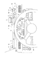
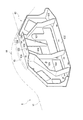
図6には、モニタフレーム63が示されている。モニタフレーム63は、図3に示したメインモニタ62を支持するためのフレームであり、図6では、車両の前方側から見た図が示されている。モニタフレーム63は、運転者側に対向しメインモニタ62を支持する略八角形の支持面部631を有している。支持面部631の下端縁には、モニタフレーム63自身をキャブ3内の他のフレームに取り付けるための取付面部632が一体に設けられ、支持面部631の上端縁には、支持フレーム10を取り付けるための固定面部633が一体に設けられている。
FIG. 6 shows a
支持面部631の他の周縁や、支持面部631の裏面(図示されている側の面)には、モニタフレーム63の剛性向上のための面状部分が、金属プレートの曲げ加工や溶接により付加されている。特に、下方の取付面部632と上方の固定面部633との間には、下端が取付面部632の上面に接合され、上端が固定面部633の下面に接合され、上下にわたって連続した端縁が支持面部631の裏面に接合された3枚のリブプレート634,635,636が設けられている。加えて、略三角形のリブプレート637が固定面部633の下面と支持面部631の裏面とに跨って設けられている。
A planar portion for improving the rigidity of the
支持面部631は、メインモニタ62の各種メータやコーションランプを取り付ける関係で多数の開口部分を有し、それ単体では剛性が低い。しかし、リブプレート634〜637を含む面状部分を支持面部631に対して立設したり、それらのうちのリブプレート634〜636の上下端を取付面部632および固定面部633に接続したりすることで、支持面部631の剛性を向上させるのみならず、固定面部633上に取り付けられる支持フレーム10を確実に支持できるよう、モニタフレーム63全体の剛性向上が図られており、固定面部633へ支持フレーム10を堅固に固定することが可能である。
The
このようなモニタフレーム63は、ダッシュカバー61の山状部64で覆われる。山状部64の固定面部633に対応した位置には、支持フレーム10の固定ボックス15が入れ込まれる設置開口65が設けられる。固定面部633には4つのボルト挿通孔638が設けられ、固定面部633の裏面には各ボルト挿通孔638に対応した図示略の裏ナットが設けられている。固定面部633に載置された支持フレーム10は、固定ボックス15を貫通して前記裏ナットに螺入されるボルトにより固定される。
Such a
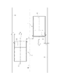
図7をも参照し、本実施形態での組立手順について説明する。
ダッシュカバー61の山状部64には、予め設置開口65を設けておき、設置開口65からは、支持フレーム10内に引き込まれる種種のケーブルが引き出しておく。また、赤外線カメラ21および赤外線ランプ22,23を、第1、第2カバー12,13に予め取り付けておき、警告装置16のLED161〜613を、ベースフレーム11内に取り付けておく。
With reference also to FIG. 7, the assembly procedure in the present embodiment will be described.
An
そして先ず、支持フレーム10のベースフレーム11を設置開口65に臨む固定面部633に固定する。この際には、ベースフレーム11の下面に設けられた固定ボックス15を設置開口65に入れ込んで固定面部633上に載置し、上述したようにボルトで固定する。
First, the
次いで、ベースフレーム11に取り付けられた警告装置16のケーブル、および第1、第2カバー12,13に取り付けられた赤外線カメラ21、赤外線ランプ22,23のケーブルを、設置開口65から引き出されたケーブルとコネクタを介して結線するとともに、ベースフレーム11内に体良く配線する。この後、第1、第2カバー12,13をベースフレーム11に対して取り付けるとともに、中央部10Aにあっては、センターカバー14を第1、第2カバー12,13間に跨設するようにして取り付ける。
Next, the cable of the
このような支持フレーム10は、ベースフレーム11、第1、第2カバー12,13単体でも、チャンネル形状の断面を有しているために、剛性面では優位であるが、さらに、ベースフレーム11に第1、第2カバー12,13が取り付けられた状態では、四角形の閉断面を形成することになるため、剛性を格段に向上させることができて、振動やゆれに確実に対抗できるようになっている。
Such a
なお、本発明は前述の実施形態に限定されるものではなく、本発明の目的を達成できる範囲での変形、改良等は本発明に含まれるものである。
例えば、前記実施形態では、赤外線ランプは左右に1つずつ設けられていたが、少なくとも左右に1つずつ設ければよいので、さらに赤外線ランプの数を増やしてもよい。
前記実施形態では、支持フレーム10が運転席301側に向けて拡開した形状であったが、車幅方向の沿って真っ直ぐな形状であってもよい。
It should be noted that the present invention is not limited to the above-described embodiments, and modifications, improvements, and the like within the scope that can achieve the object of the present invention are included in the present invention.
For example, in the above-described embodiment, one infrared lamp is provided on each of the left and right, but at least one infrared lamp may be provided on each of the left and right, and the number of infrared lamps may be further increased.
In the above-described embodiment, the
前記実施形態では、第1、第2カバー12,13およびセンターカバー14が個別に設けられていたが、それらを一体もののカバーとして製作してもよい。
前記実施形態では、ベースフレーム11に固定片115が設けられていたが、このような固定片115を固定ボックス15に設けてもよい。この場合、固定ボックス15に対して第1、第2カバー12,13およびセンターカバー14を直接取り付けることで、ベースフレーム11が存在しない構造としてもよい。また、この場合において、一体もののカバーを採用してもよい。
また、ベースフレームを採用しない場合には、各カバーの天面部の裏側や垂下部の裏側等にケーブルを保持させればよい。
In the said embodiment, although the 1st,
In the embodiment, the fixing
Further, when the base frame is not adopted, the cable may be held on the back side of the top surface portion of each cover, the back side of the hanging portion, or the like.
本発明は、鉱山等で用いられる大型ダンプトラックに利用することができる。 The present invention can be used for a large dump truck used in a mine or the like.
1…大型ダンプトラック、2…ボディ、3…キャブ、4…ベッセル、6…ダッシュボード、10…支持フレーム、10A…中央部、10B…第1アーム部、10C…第2アーム部、11…ベースフレーム、12…第1カバー、13…第2カバー、15…固定ボックス、21…撮像装置である赤外線カメラ、22,23…照明装置である赤外線ランプ、31…撮像位置調整手段であるブラケット、61…ダッシュカバー、63…モニタフレーム、111…底面部、112…立上部、121,131…天面部、122,132…垂下部、301…運転席、302…ハンドル。 DESCRIPTION OF SYMBOLS 1 ... Large dump truck, 2 ... Body, 3 ... Cab, 4 ... Vessel, 6 ... Dashboard, 10 ... Support frame, 10A ... Center part, 10B ... 1st arm part, 10C ... 2nd arm part, 11 ... Base Frame, 12 ... 1st cover, 13 ... 2nd cover, 15 ... Fixed box, 21 ... Infrared camera which is imaging device, 22, 23 ... Infrared lamp which is illumination device, 31 ... Bracket which is imaging position adjustment means, 61 DESCRIPTION OF SYMBOLS ... Dash cover, 63 ... Monitor frame, 111 ... Bottom part, 112 ... Upright part, 121, 131 ... Top part, 122, 132 ... Hanging part, 301 ... Driver's seat, 302 ... Handle.
Claims (5)
前記ボディの前方上部であって、車幅方向の一方側に寄って載置されたキャブと、
前記ボディの後方上部に載置されたベッセルとを備えた
大型ダンプトラックにおいて、
前記キャブ内には、
運転者が前方を向いて着座する運転席と、
運転席の正面位置で回転操作されるハンドルと、
前記ハンドルの前方に設けられたダッシュボードと、
前記ハンドルより前方で、かつ該ハンドルの回転中心よりも車幅方向の他方側に寄せて配置される撮像装置と、
前記ハンドルの回転中心に対して車幅方向の両側に配置される少なくとも一対の照明装置と、
前記撮像装置および前記照明装置を支持する支持フレームと、
前記ダッシュボード内に収容されたモニタフレームとが設けられ、
前記支持フレームは、前記モニタフレームに固定される中央部、前記中央部から車幅方向の一方側に延出した第1アーム部、前記中央部から車幅方向の他方側に延出した第2アーム部で形成され、
前記第1、第2アーム部は、前記撮像装置および前記照明装置のうちの少なくとも前記照明装置が取り付けられる天面部と、前記天面部に一体でかつ車幅方向に沿った垂下部とを有している
ことを特徴とする大型ダンプトラック。 Body,
A front upper portion of the body, and a cab placed on one side in the vehicle width direction;
In a large dump truck having a vessel placed on the rear upper part of the body,
In the cab,
A driver seat where the driver is seated facing forward,
A handle that is rotated in front of the driver's seat,
A dashboard provided in front of the handle;
An imaging device disposed in front of the handle and closer to the other side in the vehicle width direction than the center of rotation of the handle;
At least a pair of lighting devices disposed on both sides in the vehicle width direction with respect to the rotation center of the handle;
A support frame that supports the imaging device and the illumination device;
A monitor frame housed in the dashboard,
The support frame includes a central portion fixed to the monitor frame, a first arm portion extending from the central portion to one side in the vehicle width direction, and a second arm extending from the central portion to the other side in the vehicle width direction. Formed by the arm part,
The first and second arm portions include a top surface portion to which at least the illumination device is attached, and a hanging portion that is integral with the top surface portion and extends in the vehicle width direction. A large dump truck characterized by
前記第1、第2アーム部は、前記天面部と対向した底面部と、前記底面部に一体でかつ車幅方向に沿った立上部とをさらに有している
ことを特徴とする大型ダンプトラック。 The large dump truck according to claim 1,
The first and second arm portions further include a bottom surface portion facing the top surface portion, and a raised portion that is integral with the bottom surface portion and extends in the vehicle width direction. .
前記支持フレームは、
前記第1、第2アーム部に対応した前記底面部および前記立上部を有するベースフレームと、
前記第1アーム部に対応した前記前記天面部および前記垂下部を有する第1カバーと、 前記第2アーム部に対応した前記前記天面部および前記垂下部を有する第2カバーとを備え、
前記第1、第2カバーが前記ベースフレームに取り付けられる
ことを特徴とする大型ダンプトラック。 The large dump truck according to claim 2,
The support frame is
A base frame having the bottom portion and the raised portion corresponding to the first and second arm portions;
A first cover having the top surface portion and the hanging portion corresponding to the first arm portion; and a second cover having the top surface portion and the hanging portion corresponding to the second arm portion;
The large dump truck, wherein the first and second covers are attached to the base frame.
前記支持フレームは、前記ベースフレームの前記中央部に対応した位置で箱状の固定ボックスを介して前記モニタフレームに固定される
ことを特徴とする大型ダンプトラック。 In the large dump truck according to claim 3,
The large-sized dump truck, wherein the support frame is fixed to the monitor frame via a box-shaped fixed box at a position corresponding to the central portion of the base frame.
前記支持フレームは、平面視にて前記運転席側に拡開した弓形状である
ことを特徴とする大型ダンプトラック。 The large dump truck according to claim 4,
The large dump truck, wherein the support frame has a bow shape that is widened toward the driver's seat in plan view.
Priority Applications (1)
| Application Number | Priority Date | Filing Date | Title |
|---|---|---|---|
| JP2011066086A JP2012201166A (en) | 2011-03-24 | 2011-03-24 | Large dump truck |
Applications Claiming Priority (1)
| Application Number | Priority Date | Filing Date | Title |
|---|---|---|---|
| JP2011066086A JP2012201166A (en) | 2011-03-24 | 2011-03-24 | Large dump truck |
Publications (1)
| Publication Number | Publication Date |
|---|---|
| JP2012201166A true JP2012201166A (en) | 2012-10-22 |
Family
ID=47182598
Family Applications (1)
| Application Number | Title | Priority Date | Filing Date |
|---|---|---|---|
| JP2011066086A Withdrawn JP2012201166A (en) | 2011-03-24 | 2011-03-24 | Large dump truck |
Country Status (1)
| Country | Link |
|---|---|
| JP (1) | JP2012201166A (en) |
-
2011
- 2011-03-24 JP JP2011066086A patent/JP2012201166A/en not_active Withdrawn
Similar Documents
| Publication | Publication Date | Title |
|---|---|---|
| KR101822890B1 (en) | Front Vedeo Camera for Vehicles | |
| JP5936288B2 (en) | Vehicle imaging device | |
| JP5763381B2 (en) | Large dump truck | |
| JP6349996B2 (en) | Tractor cabin | |
| CN105408168B (en) | Work vehicle | |
| JP6096616B2 (en) | Tractor | |
| JP5013192B2 (en) | Motorcycle front lighting structure | |
| JP2004082829A (en) | On-vehicle camera | |
| US11753103B2 (en) | Straddle vehicle | |
| CN105579291B (en) | Tractor | |
| JP2009029178A (en) | Mirror device | |
| CN114103822B (en) | Mobile | |
| JP6911829B2 (en) | Work vehicle | |
| KR101445176B1 (en) | Cameram and Ultrasonic sensor adhesive device for vehicle | |
| JP2012201166A (en) | Large dump truck | |
| JP2016049897A (en) | Driving assistance device | |
| WO2014061528A1 (en) | Wheeled work machine | |
| KR20190091629A (en) | Observing Appratus for Displaying Front-Side Blind Spot by A-Pillar of Vehicle | |
| US11242233B2 (en) | Method for alerting a person near a vehicle when said vehicle performs a movement and vehicle | |
| JP6770413B2 (en) | Vehicle interior camera mounting structure | |
| JP7485143B2 (en) | Tractor | |
| JP6895865B2 (en) | Tractor | |
| JP2010058736A (en) | Specially equipped vehicle | |
| EP3281825B1 (en) | Rear-view mirror unit | |
| US20210009213A1 (en) | Work vehicle |
Legal Events
| Date | Code | Title | Description |
|---|---|---|---|
| A300 | Withdrawal of application because of no request for examination |
Free format text: JAPANESE INTERMEDIATE CODE: A300 Effective date: 20140603 |