JP2004082829A - On-vehicle camera - Google Patents
On-vehicle camera Download PDFInfo
- Publication number
- JP2004082829A JP2004082829A JP2002245069A JP2002245069A JP2004082829A JP 2004082829 A JP2004082829 A JP 2004082829A JP 2002245069 A JP2002245069 A JP 2002245069A JP 2002245069 A JP2002245069 A JP 2002245069A JP 2004082829 A JP2004082829 A JP 2004082829A
- Authority
- JP
- Japan
- Prior art keywords
- mirror
- section
- vehicle
- imaging unit
- unit
- Prior art date
- Legal status (The legal status is an assumption and is not a legal conclusion. Google has not performed a legal analysis and makes no representation as to the accuracy of the status listed.)
- Pending
Links
Images


Abstract
Description
【0001】
【発明の属する技術分野】
車両に搭載されるカメラに関する。
【0002】
【従来の技術及び発明が解決しようとする課題】
従来より、車載カメラの用途は種々知られている。例えば車両前方を認識するための車外監視カメラを取り付け、道路上の白線を認識して車間制御や定速走行制御を行うオートクルーズ制御に用いたり、赤外線監視カメラを取り付け、車両前方の状況を撮影して夜間のドライバの視認補助に用いたりすることが考えられている。これらの車載カメラは、例えば図5(a)に示すように、カメラ100をブラケット101に取り付け、そのブラケット101を図示しないインナーミラー上方(フロントガラス102と天井103との間)のリインホースメント104にネジ105によって固定されている。この場合、作業者は上を向いて作業(ネジ締め等)をしなければならない。また、作業中カメラ100が落下しないような構造を必要とする。
【0003】
一方、図5(b)に示すように、カメラ100をインナミラー110のミラーケース部111内に搭載する構造も知られている。この場合は予めミラーケース部111内にカメラ100を搭載しておき、そのミラーケース部111自体を車両に取り付ければよいので作業性は向上する。しかし、カメラ光軸を固定するためにはカメラ100を内蔵したミラーケース部111の(車体に対する)位置を固定しておく必要があるのに対して、鏡面部自体は角度調整可能な構成にする必要があり、鏡面部の角度調整機構(図示せず)を備える必要がある。その結果、ミラーケース部111が大きくなってしまっていた。これはデザイン性を損ねる原因ともなっていた。
【0004】
そこで本発明は、上述した問題点を解決し、インナーミラー内部や近傍にカメラを搭載しながら、デザイン性を損ねないようにした車載カメラを提供することを目的とする。
【0005】
【課題を解決するための手段及び発明の効果】
上述した問題点を解決するためになされた請求項1に記載の車載カメラは、撮像部が、インナーミラーのフロントガラス又は天井への取付部の内部あるいはその近傍に、制御回路基板部とは分離して配置されている。また、制御回路基板部については、例えば請求項2に示すように、ミラーケース部内に配置することが考えられる。
【0006】
このように撮像部と制御回路基板部を分離して配置すれば、ミラーケース部内には撮像部を配置しなくてよくなり、ミラーケース部の位置を固定しておく必要がない。つまり、ミラーケース部の位置は変化しても構わないため、ミラーケース内において鏡面部の角度を調整するための構成を採用しなくてもよく、ミラーケース自体は相対的に小さくてもよくなる。そのため、デザイン性を極力損ねないようにすることができる。
【0007】
また、撮像部をインナーミラー取付部内に配置し、制御回路基板部をミラーケース部内に配置した場合には、撮像部と制御回路基板部との間の配線をミラーケースに連結しているミラーステー内に通すことも可能となり、インナーミラーユニットでカメラの構成が完結する。そのため、例えば車種やグレードによってカメラ機能を変更する場合の対応が容易になる。
【0008】
なお、このようなインナーミラーミラーユニット単位でカメラの構成が完結するという効果は得られないが、制御回路基板部を例えば車両天井内に配置することも考えられる。但し、ノイズ防止等のために、制御回路基板部が撮像部から離れすぎないようにすることが必要である。
【0009】
上述のように、撮像部はインナーミラー取付部の内部あるいはその近傍に配置すればよいが、取付部内部ではなく近傍に配置する場合には、請求項3に示すように、車両運転者の視点を基準としてミラーケース部の死角に極力入るようにすることが好ましい。このようにすれば、車両運転者の視界を極力遮ることがなくなり、且つデザイン性を損なわないようにすることができる。
【0010】
ところで、例えば図5(b)に示すように、ミラーケース部111内にカメラ100を配置する場合、カメラ100自体を上下固定ネジ112a及び左右固定ネジ113aによってミラーケース部111に対して固定すると共に、カメラ100自体の上下左右の方向調整を上下調整スクリュー112b及び左右調整スクリュー113bによって実行していた。しかし、このような調整機構では、ねじれを修正することはできない。
【0011】
そこで、請求項4に示す構成を採用することによって、撮像部固定部材又はベース部材の少なくともいずれか一方に設けた凸部が相手側部材と当接することによって両部材の3次元的な位置関係を変更できる。
また、凸部は、球面状のような滑らかな曲面に形成され、相手側との位置関係が変更することで曲面上の当接位置が変更するような構成であってもよいし、あるいは、例えば円錐状のような頂点部分の1点のみで相手側と当接するような構成であってもよい。
【0012】
締結構造については例えばネジを用いたものが考えられるが、凸部の周囲に3箇所のネジ止め部を有し、それらの各位置におけるネジの螺合度合いを調整することで3次元的に位置調整することが考えられる。
また、請求項5に示すように、締結構造は、撮像部を撮像部固定部材に固定するための構造としても機能するよう構成してもよい。
【0013】
【発明の実施の形態】
以下、本発明が適用された実施例について図面を用いて説明する。なお、本発明の実施の形態は、下記の実施例に何ら限定されることなく、本発明の技術的範囲に属する限り種々の形態を採りうることは言うまでもない。
【0014】
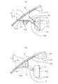
図1は、実施例における車載カメラの取付位置等を示す概略説明図である。本実施例の車載カメラは撮像部3aと制御回路基板部3bを有しており、車両のフロントガラス4の車内側に吊り下げ固定されたインナーミラーユニット内部に配置されている。図1(a)はインナーミラーユニットを側方から見た概略図であり、図1(b)はインナーミラーユニットを斜め後方から(つまりフロントガラス4側から)見た概略図である。
【0015】
まず、インナーミラーユニットについて簡単に説明する。
本ユニットは、インナーミラー2と、インナーミラーステー5と、インナーミラー取付部7とを備えている。ここでインナーミラー2は、略長方形板状の鏡面部2aがミラーケース部2bに収納されて構成されている。そして、そのミラーケース部2bの背面側(正面側に鏡面部2aが配置されるため、その反対側)の左右方向中央付近において、インナーミラーステー5と接続している。この接続部分においてミラーケース部2bは、インナーミラーステー5に対して任意方向に所定角度回転可能に取り付けられている。このような構成によって、乗員(特にドライバ)は、運転席に座った状態でインナーミラー2の鏡面部2aを介して車両後方を確認するのに適切な上下及び左右方向角度となるよう、ミラーケース部2bを手で調整することができる。
【0016】
一方、インナーミラーステー5の他端側は、フロントガラス4の車内側に吊り下げ固定されたインナーミラー取付部7に固定されている。なお、インナーミラー取付部7に対してインナーミラーステー5が上下方向に回転可能に取り付けてもよいし、相対位置が変化しないよう取り付けても良い。そして、このインナーミラー取付部7は、フロントガラス4に取り付けられている。この場合、インナーミラー取付部7自体をフロントガラス4に直接固着してもよいが、本実施例ではフロントガラス4に固着したボタン41に引っ掛けるようにして取り付けられている。
【0017】
また、このインナーミラー取付部7は、図2に示すように、略椀状の上筐体部71と平板状の下筐体部72とから構成されている。両者は図1(a)に示すフロントガラス4側の縁近辺で2箇所、その反対側(つまりミラーケース部2b側)の縁近辺で1箇所、計3箇所において固定ネジ81によって固定される。そして、その内部に収納空間が形成されることとなる。
【0018】
上筐体部71の一側面にはインナーミラーステー5が取り付けられており、その反対側の側面には上述したボタン41に引っ掛けるための引掛部71bが形成されている。また、その引掛部71bの両脇には、後述する撮像部3aが車両前方を撮影できるようにするためのカメラ開口部71aが形成されている。
【0019】
次に、車載カメラの撮像部3a及び制御回路基板部3bの配置を説明する。
撮像部3aは、2つ存在し、インナーミラー取付部7内に収納されている。この撮像部3aは略円柱状であって、撮像部固定部材31に固定されており、その撮像部固定部材31がインナーミラー取付部7の下筐体部72に載置される。なお、この下筐体部72が特許請求の範囲における「ベース部材」に相当する。
【0020】
さらに具体的に説明すると、撮像部固定部材31は、底板31a上に2枚の背面板31bが立設されて形成されている。そして、その各背面板31bにそれぞれ撮像部3aが取り付けられている。したがって、撮像部固定部材31の位置を調整すれば撮像部3aの位置も調整されることとなる。
【0021】
この撮像部固定部材31は上述のようにインナーミラー取付部7の下筐体部72に載置されるのであるが、この下筐体部72の中央付近には、インナーミラー取付部7内部の収納空間に向けて突出する凸部72aが形成されている。本実施例の凸部72aは、図2又は図3(a),(b)に示すように、球面の一部の形状とされている。そして、この球面状の凸部72aの上に撮像部固定部材31の底板31aが載置され、3本の位置調整ネジ82によって下筐体部72と底板31aとが締結される。
【0022】
ここで、下筐体部72には凸部72aの周囲において略3等分するような位置にそれぞれ長穴が形成されており、一方、底板31aにはその長穴に対応する位置に通常のネジ穴が形成されている。なお、これら下筐体部72の長穴、底板31aのネジ穴及び位置調整ネジ82が、特許請求の範囲における「締結構造」に相当する。そして、位置調整ネジ82による締結度合いを各位置で変化させることによって、下筐体部72に対する底板31aの3次元的な位置関係を調整した状態で、それら両部材72,31aを締結できるように構成されている。
【0023】
例えば図3(a)に示すように、撮像部3aを前方側に傾けたり、 図3(b)に示すように、撮像部3aを左右いずれかの方向に傾けたりすることができる。また、このように前後左右に傾けるだけでなく、3本の位置調整ネジ82の締結度合を調整することで、任意方向に傾けることができる。
【0024】
なお、このような撮像部3aが位置調整のために傾くことを考慮して、インナーミラー取付部7の上筐体部71におけるカメラ開口部71aは略円柱状の撮像部3aの外形よりも大きく形成されている。
一方、制御回路基板部3bは、ミラーケース部2bに収納されている。具体的には、図1に示すように、ミラーケース部2b内において鏡面部2aより背面側に配置されている。そして、制御回路基板部3bには3本の通信線が接続されており、その内の1本は図示しない車内LANに接続するためのLAN用通信線3cであり、残りの2本は撮像部3aからの信号を入力するためのカメラ用通信線3dである。LAN用通信線3cは、インナーミラーステー5及びフロントガラスに沿って天井10まで配置され、天井10内部を通して車載LANに接続されている。一方、2本のカメラ用通信線3dはインナーミラーステー5内部を通ってインナーミラー取付部7に至り、各撮像部3aと接続されている。
【0025】
このような構成の本実施例の車載カメラによれば、次のような効果が発揮される。
(a)撮像部3aはインナーミラー取付部7内に収納され、制御回路基板部3bはミラーケース部2bに収納されている。このように撮像部3aと制御回路基板部3bとを分離して配置しているため、ミラーケース部2b内には撮像部3aを配置しなくてよくなり、ミラーケース位置を固定しておく必要がない。つまり、本実施例のようにミラーケース部2b自体がインナーミラーステー5に対して任意方向に所定角度回転可能な構成を採用でき、従来技術として説明した「ミラーケース部2b内において鏡面部2aの角度を調整するための構成」を採用しなくてもよい。そのため、ミラーケース部2b自体を相対的に小さくでき、デザイン性を極力損ねないようにすることができる。
【0026】
(b)本実施例では、撮像部3aをインナーミラー取付部7内に収納し、制御回路基板部3bをミラーケース部2bに収納しているため、撮像部3aと制御回路基板部3bとの間の配線をインナーミラーステー5内に通すことができ、インナーミラーユニットでカメラの構成が完結する。そのため、例えば車種やグレードによってカメラ機能を変更する場合の対応が容易になる。
【0027】
例えば一般的には前方認識用カメラだけとし、上級車種では赤外線暗視やレーンキープ用の機能も備えるカメラを搭載する、といった対応の場合、インナーミラーユニット単位でそのような機能を準備しておけば、搭載したい機能に応じたインナーミラーユニットを選択して該当車に取り付ければよくなる。
【0028】
(c)また、本実施例では、位置調整ネジ82による締結度合いを各位置で変化させることによって、下筐体部72に対する底板31aの3次元的な位置関係を調整でき、その結果、撮像部3aの撮像方向(光軸方向)を3次元的に調整可能である。
【0029】
[その他]
(1)上記実施例においては、図3(a),(b)に示すように、インナーミラー取付部7の下筐体部72の中央付近に凸部72aを設け、その上に撮像部固定部材31の底板31aを載置することによって、下筐体部72に対する底板31aの3次元的な位置関係を調整可能な構成とした。しかし、図3(c)に示すように、撮像部固定部材31の底板31aに凸部90を設け、その凸部90が当接するように底板31aを下筐体部72に載置してもよい。なお、底板31aに設けた凸部90は、図3(a),(b)に示す下筐体部72の凸部72aと同様の形状で構わない。
【0030】
また、図3(a),(b)に示す凸部72aは、球面状であり滑らかな曲面に形成されている。そのため、底板31aの傾きが変化する場合には、凸部72aと底板31aとの当接位置が変化する構成であった。しかし、例えば図3(d)に示すように、円錐状の凸部172aとし、その頂点部分の1点のみで相手側である底板31aと当接するような構成であってもよい。もちろんこの場合も、図3(c)に示した例と同様に、凸部を底板31a側に設けても良い。
【0031】
(2)上記実施例においては、図1に示すように、撮像部3aをインナーミラー取付部7内に収納したが、例えば図4(a)に示すように、インナーミラー取付部7の近傍であれば外部に取り付けても良い。この場合は、下筐体部72に設けた凸部72aをインナーミラー取付部7内部ではなく、外部に向けて突出するよう形成する。そして、その凸部72aに当接させて撮像部固定部材31の底板31aを取り付ける。この取付はネジにて行えばよい。なお、実際の取付作業は車室内で行う必要はない。つまり、予め撮像部固定部材31に撮像部3aを取り付けておいたインナーミラーユニットを準備し、それをボタン41に引っ掛ければよいからである。
【0032】
なお、このようにインナーミラー取付部7の外部に配置する場合には、車両運転者の視点を基準としてミラーケース部2bの死角に極力入るようにすることが好ましい。このようにすれば、車両運転者の視界を極力遮ることなく、且つデザイン性を損なわないようにすることができる。
【0033】
(3)上記実施例においては、図1に示すように、制御回路基板部3bをミラーケース部2bに収納したが、図4(b)に示すように天井10の内部に配置しても良い。また、天井10にオーバーヘッドコンソールが配置される場合には、そのオーバーヘッドコンソール内部に配置してもよい。この場合も、撮像部3aと制御回路基板部3bとは分離配置されるため、ミラーケース部2b内には撮像部3aを配置しなくてよく、ミラーケース部の位置を固定しておく必要がない。
【0034】
但し、このような構成を採用する場合には、ノイズ防止等のために、制御回路基板部3bが撮像部3aから離れすぎないようにすることが好ましい。
(4)上記実施例では、インナーミラー取付部7の上筐体部71と下筐体部72とは固定ネジ81によって固定し、凸部72aを設けた下筐体部72に底板31aを載置して両者の位置関係が調整可能とし、位置調整ネジ82によって下筐体部72と底板31aとを締結するようにした。
【0035】
しかし、凸部72aを設けず、また固定ネジ81と位置調整ネジ82の2種類のネジを使用せずに1種類のネジによって両機能を果たすような構成を採用しても良い。例えば図2において、下筐体部72の凸部72a及びその周囲の長穴を設けず、撮像部固定部材31を下筐体部72に固定する。その際、撮像部固定部材31の底板31aを設けず、背面板31bを直接下筐体部72に固定する構造であってもよい。そして、このように撮像部3aが固定された下筐体部72を上筐体部71に取り付ける構造を工夫する。例えば、図2に示す固定ネジ81による螺着位置(3箇所)において、例えばゴム等で形成され弾性を有する円筒ブッシュを介して下筐体部72と上筐体部71を螺着する。このようにすれば、各螺着位置におけるネジの締結度合いを変えることによって円筒ブッシュの圧縮度合いが変わり、上筐体部71に対する下筐体部72の傾きを調整することができる。それでいて、下筐体部72と上筐体部71とを固定することもできる。
【図面の簡単な説明】
【図1】実施例における車載カメラの取付位置等を示す概略説明図であり、(a)はインナーミラーユニットを側方から見た概略図、(b)はインナーミラーユニットを斜め後方から見た概略図である。
【図2】インナーミラー取付部及びその内部の撮像部に関係する構成を示す概略斜視図である。
【図3】(a),(b)は実施例における撮像部の位置調整が可能であることを示す説明図、(c),(d)は別実施例の説明図である。
【図4】別実施例の説明図である。
【図5】従来技術の説明図である。
【符号の説明】
2…インナーミラー、2a…鏡面部、2b…ミラーケース部、3a…撮像部、3b…制御回路基板部、3c…LAN用通信線、3d…カメラ用通信線、4…フロントガラス、5…インナーミラーステー、7…インナーミラー取付部、31…撮像部固定部材、31a…底板、31b…背面板、41…ボタン、71…上筐体部、71a…カメラ開口部、71b…引掛部、72…下筐体部、72a,90,172a…凸部、81…固定ネジ、82…位置調整ネジ。[0001]
TECHNICAL FIELD OF THE INVENTION
The present invention relates to a camera mounted on a vehicle.
[0002]
Problems to be solved by the prior art and the invention
Conventionally, various uses of a vehicle-mounted camera have been known. For example, an external surveillance camera for recognizing the front of the vehicle is installed, and it is used for auto cruise control that recognizes white lines on the road and performs inter-vehicle control and constant speed driving control. It is also considered to be used for assisting driver's visual recognition at night. In these vehicle-mounted cameras, for example, as shown in FIG. 5A, the
[0003]
On the other hand, as shown in FIG. 5B, a structure in which the
[0004]
Accordingly, it is an object of the present invention to provide an in-vehicle camera that solves the above-described problems and does not impair the design while mounting the camera inside or near the inner mirror.
[0005]
Means for Solving the Problems and Effects of the Invention
The vehicle-mounted camera according to
[0006]
If the imaging section and the control circuit board section are separated as described above, the imaging section does not need to be arranged in the mirror case section, and there is no need to fix the position of the mirror case section. That is, since the position of the mirror case may be changed, it is not necessary to employ a configuration for adjusting the angle of the mirror surface in the mirror case, and the mirror case itself may be relatively small. Therefore, it is possible to prevent the design from being impaired as much as possible.
[0007]
When the imaging unit is arranged in the inner mirror mounting unit and the control circuit board is arranged in the mirror case, the mirror stay connecting the wiring between the imaging unit and the control circuit board to the mirror case is connected. The camera can be completed by the inner mirror unit. For this reason, for example, it is easy to cope with a case where the camera function is changed depending on a vehicle type or a grade.
[0008]
It should be noted that the effect that the configuration of the camera is completed in units of such an inner mirror mirror unit cannot be obtained, but it is also conceivable to arrange the control circuit board unit in a vehicle ceiling, for example. However, it is necessary to prevent the control circuit board unit from being too far from the imaging unit in order to prevent noise.
[0009]
As described above, the imaging unit may be disposed inside or near the inner mirror mounting unit. It is preferable to enter the blind spot of the mirror case portion as much as possible with reference to the following. In this way, it is possible to prevent the view of the vehicle driver from being obstructed as much as possible and not to impair the design.
[0010]
By the way, as shown in FIG. 5B, when the
[0011]
Therefore, by adopting the configuration described in claim 4, the projection provided on at least one of the imaging unit fixing member and the base member comes into contact with the mating member so that a three-dimensional positional relationship between the two members can be obtained. Can be changed.
Further, the convex portion may be formed in a smooth curved surface such as a spherical shape, and may be configured such that the contact position on the curved surface is changed by changing the positional relationship with the counterpart, or For example, a configuration in which only one point of a vertex portion such as a cone abuts on the other side may be used.
[0012]
As the fastening structure, for example, one using screws is conceivable. However, three screwing portions are provided around the convex portion, and the degree of screwing at each of those positions is adjusted to three-dimensionally position the screw. Adjustment is conceivable.
Further, as described in
[0013]
BEST MODE FOR CARRYING OUT THE INVENTION
Hereinafter, embodiments to which the present invention is applied will be described with reference to the drawings. It is needless to say that the embodiments of the present invention are not limited to the following examples, and can take various forms within the technical scope of the present invention.
[0014]
FIG. 1 is a schematic explanatory view showing a mounting position and the like of a vehicle-mounted camera in an embodiment. The in-vehicle camera according to the present embodiment has an imaging unit 3a and a control circuit board unit 3b, and is disposed inside an inner mirror unit suspended and fixed inside a windshield 4 of the vehicle. FIG. 1A is a schematic view of the inner mirror unit as viewed from the side, and FIG. 1B is a schematic view of the inner mirror unit as viewed obliquely from behind (that is, from the windshield 4 side).
[0015]
First, the inner mirror unit will be briefly described.
This unit includes an
[0016]
On the other hand, the other end of the
[0017]
As shown in FIG. 2, the inner
[0018]
An
[0019]
Next, the arrangement of the imaging unit 3a and the control circuit board unit 3b of the vehicle-mounted camera will be described.
There are two imaging units 3a, which are housed in the inner
[0020]
More specifically, the imaging
[0021]
The imaging
[0022]
Here, a long hole is formed in the
[0023]
For example, as shown in FIG. 3A, the imaging unit 3a can be tilted to the front side, and as shown in FIG. 3B, the imaging unit 3a can be tilted to either the left or right direction. In addition to tilting the three position adjusting screws 82 in addition to tilting the front and rear and left and right in this manner, the three position adjusting screws 82 can be tilted in any direction.
[0024]
In consideration of such an inclination of the imaging unit 3a for position adjustment, the camera opening 71a in the
On the other hand, the control circuit board 3b is housed in the mirror case 2b. Specifically, as shown in FIG. 1, it is arranged on the rear side of the mirror surface portion 2a in the mirror case portion 2b. The control circuit board 3b is connected with three communication lines, one of which is a LAN communication line 3c for connecting to an in-vehicle LAN (not shown), and the other two are imaging units. This is a camera communication line 3d for inputting a signal from 3a. The LAN communication line 3c is arranged along the
[0025]
According to the vehicle-mounted camera of this embodiment having such a configuration, the following effects are exhibited.
(A) The imaging section 3a is housed in the inner
[0026]
(B) In the present embodiment, since the imaging section 3a is housed in the inner
[0027]
For example, in general, only cameras for forward recognition are used, and in advanced models, cameras equipped with infrared night vision and lane keeping functions are installed.Such functions should be prepared for each inner mirror unit. For example, you can select the inner mirror unit according to the function you want to install and attach it to the car.
[0028]
(C) In the present embodiment, the three-dimensional positional relationship of the bottom plate 31a with respect to the
[0029]
[Others]
(1) In the above embodiment, as shown in FIGS. 3A and 3B, the convex portion 72a is provided near the center of the
[0030]
In addition, the convex portion 72a shown in FIGS. 3A and 3B has a spherical shape and is formed into a smooth curved surface. Therefore, when the inclination of the bottom plate 31a changes, the contact position between the protrusion 72a and the bottom plate 31a changes. However, for example, as shown in FIG. 3D, a conical convex portion 172a may be used, and only one point at the apex of the convex portion 172a may come into contact with the bottom plate 31a on the other side. Of course, also in this case, similarly to the example shown in FIG. 3C, the convex portion may be provided on the bottom plate 31a side.
[0031]
(2) In the above embodiment, as shown in FIG. 1, the imaging section 3a is housed in the inner
[0032]
In this case, when it is disposed outside the inner
[0033]
(3) In the above embodiment, the control circuit board 3b is housed in the mirror case 2b as shown in FIG. 1, but may be arranged inside the
[0034]
However, when such a configuration is adopted, it is preferable that the control circuit board unit 3b is not too far from the imaging unit 3a in order to prevent noise and the like.
(4) In the above embodiment, the
[0035]
However, it is also possible to adopt a configuration in which the convex portion 72a is not provided, and the two functions of the fixing
[Brief description of the drawings]
BRIEF DESCRIPTION OF THE DRAWINGS FIG. 1 is a schematic explanatory view showing a mounting position of an in-vehicle camera and the like in an embodiment. It is a schematic diagram.
FIG. 2 is a schematic perspective view showing a configuration related to an inner mirror mounting section and an image pickup section inside the inner mirror mounting section.
FIGS. 3A and 3B are explanatory diagrams showing that the position of the imaging unit can be adjusted in the embodiment, and FIGS. 3C and 3D are explanatory diagrams of another embodiment.
FIG. 4 is an explanatory diagram of another embodiment.
FIG. 5 is an explanatory diagram of a conventional technique.
[Explanation of symbols]
2 inner mirror, 2a mirror surface portion, 2b mirror case portion, 3a imaging portion, 3b control circuit board portion, 3c communication line for LAN, 3d communication line for camera, 4 front glass, 5 inner Mirror stay, 7 inner mirror mounting portion, 31 imaging member fixing member, 31a bottom plate, 31b rear plate, 41 button, 71 upper housing portion, 71a camera opening portion, 71b hook portion, 72 ... Lower housing part, 72a, 90, 172a ... convex part, 81 ... fixing screw, 82 ... position adjusting screw.
Claims (5)
前記撮像部については、インナーミラーのフロントガラス又は天井への取付部の内部あるいはその近傍に、前記制御回路基板部とは分離して配置したこと
を特徴とする車載カメラ。A camera having an imaging unit and a control circuit board unit, which is mounted on a vehicle,
The on-vehicle camera according to claim 1, wherein the image pickup unit is disposed inside or near a portion where the inner mirror is attached to a windshield or a ceiling separately from the control circuit board unit.
前記制御回路基板部は、前記インナーミラーの鏡面部を収納するミラーケース部内に配置したこと
を特徴とする車載カメラ。The vehicle-mounted camera according to claim 1,
The on-vehicle camera according to claim 1, wherein the control circuit board section is disposed in a mirror case section that houses a mirror surface section of the inner mirror.
前記撮像部を前記インナーミラー取付部の内部ではなく近傍に配置する場合は、車両運転者の視点を基準として前記インナーミラーの鏡面部を収納するミラーケース部の死角に極力入るようにしたこと
を特徴とする車載カメラ。The vehicle-mounted camera according to claim 1 or 2,
When the imaging unit is arranged near the inside of the inner mirror mounting unit instead of the inside, it is configured to enter as much as possible into the blind spot of the mirror case unit that stores the mirror surface unit of the inner mirror based on the viewpoint of the vehicle driver. Features on-board camera.
前記撮像部を撮像部固定部材に固定し、その撮像部固定部材をベース部材に載置し、前記撮像部固定部材又は前記ベース部材の少なくともいずれか一方に凸部を設け、その凸部が相手側部材と当接することによって両部材の3次元的な位置関係が変更可能に構成されており、
前記両部材の3次元的な位置関係を調整した状態で、前記両部材を締結するための締結構造を備えていること
を特徴とする車載カメラ。The vehicle-mounted camera according to any one of claims 1 to 3,
The imaging unit is fixed to an imaging unit fixing member, the imaging unit fixing member is mounted on a base member, and a projection is provided on at least one of the imaging unit fixing member and the base member. By contacting the side members, the three-dimensional positional relationship between the two members is configured to be changeable,
An in-vehicle camera comprising a fastening structure for fastening the two members in a state where the three-dimensional positional relationship between the two members is adjusted.
前記締結構造は、前記撮像部を撮像部固定部材に固定するための構造としても機能すること
を特徴とする車載カメラ。The vehicle-mounted camera according to claim 4,
The vehicle-mounted camera according to claim 1, wherein the fastening structure also functions as a structure for fixing the imaging unit to an imaging unit fixing member.
Priority Applications (1)
| Application Number | Priority Date | Filing Date | Title |
|---|---|---|---|
| JP2002245069A JP2004082829A (en) | 2002-08-26 | 2002-08-26 | On-vehicle camera |
Applications Claiming Priority (1)
| Application Number | Priority Date | Filing Date | Title |
|---|---|---|---|
| JP2002245069A JP2004082829A (en) | 2002-08-26 | 2002-08-26 | On-vehicle camera |
Publications (1)
| Publication Number | Publication Date |
|---|---|
| JP2004082829A true JP2004082829A (en) | 2004-03-18 |
Family
ID=32053372
Family Applications (1)
| Application Number | Title | Priority Date | Filing Date |
|---|---|---|---|
| JP2002245069A Pending JP2004082829A (en) | 2002-08-26 | 2002-08-26 | On-vehicle camera |
Country Status (1)
| Country | Link |
|---|---|
| JP (1) | JP2004082829A (en) |
Cited By (24)
| Publication number | Priority date | Publication date | Assignee | Title |
|---|---|---|---|---|
| WO2006035510A1 (en) * | 2004-09-29 | 2006-04-06 | Hitachi, Ltd. | External-field-of-vehicle recognizing apparatus |
| KR100574194B1 (en) * | 2005-03-09 | 2006-06-02 | 유장호 | Car rear view mirror assembly with camera |
| WO2007079614A1 (en) * | 2006-01-13 | 2007-07-19 | Appro Technology Inc. | Rear-view mirror with front and rear bidirectional lens and screen for displaying images |
| WO2008025610A1 (en) * | 2006-08-30 | 2008-03-06 | Robert Bosch Gmbh | Image acquisition system for applications in motor vehicles |
| GB2469721A (en) * | 2009-04-23 | 2010-10-27 | Bury Sp Zoo | Vehicle windscreen mounted bipartite camera housing for detecting road traffic signs |
| KR101111230B1 (en) * | 2009-10-27 | 2012-02-14 | 주식회사 에스엘미러텍 | An apparatus having a image acquisition module in vehicles |
| KR101200265B1 (en) | 2009-09-14 | 2012-11-12 | 유장호 | Room Mirror Assembly for Automobile with Camera |
| US8356948B2 (en) | 2010-10-25 | 2013-01-22 | Honda Elesys Co., Ltd. | Structure for mounting camera on vehicle |
| JP2013184662A (en) * | 2012-03-09 | 2013-09-19 | Toyota Motor Corp | Camera cover |
| WO2014035958A1 (en) * | 2012-08-27 | 2014-03-06 | Gentex Corporation | Mirror mounting assembly |
| KR20160097923A (en) * | 2015-02-10 | 2016-08-18 | 엘지전자 주식회사 | Front Camera Module unified Rear View Mirror of Vehicles |
| CN105966325A (en) * | 2015-03-12 | 2016-09-28 | 日本电产艾莱希斯株式会社 | Vehicle-mounted camera, method of manufacturing vehicle-mounted camera, and method of manufacturing vehicle body |
| US9477143B2 (en) | 2015-01-07 | 2016-10-25 | Ricoh Company, Ltd. | Camera device |
| US9862332B2 (en) | 2012-03-19 | 2018-01-09 | Denso Corporation | In-vehicle camera |
| US10107905B2 (en) | 2007-01-25 | 2018-10-23 | Magna Electronics Inc. | Forward facing sensing system for vehicle |
| US10190610B1 (en) | 2017-10-13 | 2019-01-29 | Gentex Corporation | Mounting assembly for rearview device |
| CN109878417A (en) * | 2017-12-06 | 2019-06-14 | 丰田自动车株式会社 | Sensor carrying structure |
| JP2019099048A (en) * | 2017-12-06 | 2019-06-24 | トヨタ自動車株式会社 | Sensor mounting structure |
| WO2020006792A1 (en) * | 2018-07-04 | 2020-01-09 | 深圳市歌美迪电子技术发展有限公司 | Image processing method and mechanism, and rearview mirror |
| US10974650B2 (en) | 2017-12-11 | 2021-04-13 | Gentex Corporation | Rearview device mount and attachment method |
| US11040663B2 (en) | 2017-12-08 | 2021-06-22 | Gentex Corporation | Pre-loaded two-lobe spring twist-on rearview mounting assembly |
| US11173842B2 (en) | 2018-10-02 | 2021-11-16 | Gentex Corporation | Adjustable mounting mechanism for a rearview assembly |
| JP2022077828A (en) * | 2020-11-12 | 2022-05-24 | 本田技研工業株式会社 | Mirror harness fitting structure and mirror harness fitting method |
| WO2022210718A1 (en) * | 2021-04-02 | 2022-10-06 | 有限会社イグノス | Optical axis adjustment unit, optical instrument, optical axis adjustment system, and optical axis adjustment method |
-
2002
- 2002-08-26 JP JP2002245069A patent/JP2004082829A/en active Pending
Cited By (38)
| Publication number | Priority date | Publication date | Assignee | Title |
|---|---|---|---|---|
| WO2006035510A1 (en) * | 2004-09-29 | 2006-04-06 | Hitachi, Ltd. | External-field-of-vehicle recognizing apparatus |
| KR100574194B1 (en) * | 2005-03-09 | 2006-06-02 | 유장호 | Car rear view mirror assembly with camera |
| WO2007079614A1 (en) * | 2006-01-13 | 2007-07-19 | Appro Technology Inc. | Rear-view mirror with front and rear bidirectional lens and screen for displaying images |
| WO2008025610A1 (en) * | 2006-08-30 | 2008-03-06 | Robert Bosch Gmbh | Image acquisition system for applications in motor vehicles |
| US8917323B2 (en) | 2006-08-30 | 2014-12-23 | Robert Bosch Gmbh | Image capture system for applications in vehicles |
| US11815594B2 (en) | 2007-01-25 | 2023-11-14 | Magna Electronics Inc. | Vehicular forward-sensing system |
| US11506782B2 (en) | 2007-01-25 | 2022-11-22 | Magna Electronics Inc. | Vehicular forward-sensing system |
| US10877147B2 (en) | 2007-01-25 | 2020-12-29 | Magna Electronics Inc. | Forward sensing system for vehicle |
| US10670713B2 (en) | 2007-01-25 | 2020-06-02 | Magna Electronics Inc. | Forward sensing system for vehicle |
| US10107905B2 (en) | 2007-01-25 | 2018-10-23 | Magna Electronics Inc. | Forward facing sensing system for vehicle |
| GB2469721A (en) * | 2009-04-23 | 2010-10-27 | Bury Sp Zoo | Vehicle windscreen mounted bipartite camera housing for detecting road traffic signs |
| KR101200265B1 (en) | 2009-09-14 | 2012-11-12 | 유장호 | Room Mirror Assembly for Automobile with Camera |
| KR101111230B1 (en) * | 2009-10-27 | 2012-02-14 | 주식회사 에스엘미러텍 | An apparatus having a image acquisition module in vehicles |
| US8356948B2 (en) | 2010-10-25 | 2013-01-22 | Honda Elesys Co., Ltd. | Structure for mounting camera on vehicle |
| JP2013184662A (en) * | 2012-03-09 | 2013-09-19 | Toyota Motor Corp | Camera cover |
| US9862332B2 (en) | 2012-03-19 | 2018-01-09 | Denso Corporation | In-vehicle camera |
| US10336264B2 (en) | 2012-03-19 | 2019-07-02 | Denso Corporation | In-vehicle camera |
| US10086773B2 (en) | 2012-03-19 | 2018-10-02 | Denso Corporation | In-vehicle camera |
| US9573525B2 (en) | 2012-08-27 | 2017-02-21 | Gentex Corporation | Mirror mounting assembly |
| WO2014035958A1 (en) * | 2012-08-27 | 2014-03-06 | Gentex Corporation | Mirror mounting assembly |
| US9477143B2 (en) | 2015-01-07 | 2016-10-25 | Ricoh Company, Ltd. | Camera device |
| KR20160097923A (en) * | 2015-02-10 | 2016-08-18 | 엘지전자 주식회사 | Front Camera Module unified Rear View Mirror of Vehicles |
| WO2016129856A1 (en) * | 2015-02-10 | 2016-08-18 | 엘지전자 주식회사 | Rear-view mirror-integrated front camera module for a vehicle |
| KR101655814B1 (en) * | 2015-02-10 | 2016-09-08 | 엘지전자 주식회사 | Front Camera Module unified Rear View Mirror of Vehicles |
| CN106143319A (en) * | 2015-02-10 | 2016-11-23 | Lg电子株式会社 | The room mirror integral type front camera module of vehicle |
| CN105966325A (en) * | 2015-03-12 | 2016-09-28 | 日本电产艾莱希斯株式会社 | Vehicle-mounted camera, method of manufacturing vehicle-mounted camera, and method of manufacturing vehicle body |
| US10190610B1 (en) | 2017-10-13 | 2019-01-29 | Gentex Corporation | Mounting assembly for rearview device |
| JP2019099048A (en) * | 2017-12-06 | 2019-06-24 | トヨタ自動車株式会社 | Sensor mounting structure |
| JP2019099047A (en) * | 2017-12-06 | 2019-06-24 | トヨタ自動車株式会社 | Sensor mounting structure |
| CN109878417A (en) * | 2017-12-06 | 2019-06-14 | 丰田自动车株式会社 | Sensor carrying structure |
| US11040663B2 (en) | 2017-12-08 | 2021-06-22 | Gentex Corporation | Pre-loaded two-lobe spring twist-on rearview mounting assembly |
| US10974650B2 (en) | 2017-12-11 | 2021-04-13 | Gentex Corporation | Rearview device mount and attachment method |
| WO2020006792A1 (en) * | 2018-07-04 | 2020-01-09 | 深圳市歌美迪电子技术发展有限公司 | Image processing method and mechanism, and rearview mirror |
| US11173842B2 (en) | 2018-10-02 | 2021-11-16 | Gentex Corporation | Adjustable mounting mechanism for a rearview assembly |
| JP2022077828A (en) * | 2020-11-12 | 2022-05-24 | 本田技研工業株式会社 | Mirror harness fitting structure and mirror harness fitting method |
| JP7353256B2 (en) | 2020-11-12 | 2023-09-29 | 本田技研工業株式会社 | Mirror harness installation structure and mirror harness installation method |
| WO2022210718A1 (en) * | 2021-04-02 | 2022-10-06 | 有限会社イグノス | Optical axis adjustment unit, optical instrument, optical axis adjustment system, and optical axis adjustment method |
| JP7281148B2 (en) | 2021-04-02 | 2023-05-25 | 有限会社イグノス | Optical axis adjustment unit, optical device, optical axis adjustment system, and optical axis adjustment method |
Similar Documents
| Publication | Publication Date | Title |
|---|---|---|
| JP2004082829A (en) | On-vehicle camera | |
| US11851004B2 (en) | Rearview mirror assembly for vehicle | |
| US7492281B2 (en) | Vehicle exterior mirror assembly with blind spot indicator | |
| US6175300B1 (en) | Blind spot viewing system | |
| US7722199B2 (en) | Vehicle interior rearview mirror assembly with actuator | |
| EP2766224B1 (en) | Integrated rear camera display | |
| JP2002225629A (en) | Monitoring device for vehicle | |
| WO2011132344A1 (en) | Method of mounting camera unit, and camera unit | |
| JP2013244752A (en) | Vehicular inner mirror system, and vehicle including the same | |
| GB2210835A (en) | Vehicle forward view mirror | |
| US20230078512A1 (en) | Overhead console accessory system with shared controls, cameras, and lighting | |
| JP2015024821A (en) | Mounting device for on-vehicle camera | |
| JP2003104126A (en) | Vehicular interior monitoring device | |
| KR20190091629A (en) | Observing Appratus for Displaying Front-Side Blind Spot by A-Pillar of Vehicle | |
| JP2005112052A (en) | Cabin module and inner mirror | |
| JP6925891B2 (en) | Display device and interior member unit | |
| JP2012025234A (en) | Blind area visibility aid system for vehicle | |
| JP2018172112A (en) | Room mirror | |
| JP2001203520A (en) | Antenna unit for on-vehicle communication device | |
| US20240116442A1 (en) | Vehicular exterior rearview mirror assembly | |
| JP5257784B2 (en) | In-vehicle camera device | |
| US7498554B2 (en) | Interior rear view mirror for vehicles, preferably motor vehicles | |
| TW202233455A (en) | Removable digital rearview mirror for vehicle including a mirror base mechanism, a display device and a rear lens mechanism | |
| KR200412191Y1 (en) | Room mirror for automobile | |
| JP2011225125A (en) | Auxiliary member for attaching camera |
Legal Events
| Date | Code | Title | Description |
|---|---|---|---|
| A621 | Written request for application examination |
Free format text: JAPANESE INTERMEDIATE CODE: A621 Effective date: 20050111 |
|
| A131 | Notification of reasons for refusal |
Free format text: JAPANESE INTERMEDIATE CODE: A131 Effective date: 20080122 |
|
| A977 | Report on retrieval |
Free format text: JAPANESE INTERMEDIATE CODE: A971007 Effective date: 20080125 |
|
| A02 | Decision of refusal |
Free format text: JAPANESE INTERMEDIATE CODE: A02 Effective date: 20080729 |