JP2012201152A - Head rest - Google Patents

Head rest Download PDF

Info

Publication number
JP2012201152A
JP2012201152A JP2011065695A JP2011065695A JP2012201152A JP 2012201152 A JP2012201152 A JP 2012201152A JP 2011065695 A JP2011065695 A JP 2011065695A JP 2011065695 A JP2011065695 A JP 2011065695A JP 2012201152 A JP2012201152 A JP 2012201152A
Authority
JP
Japan
Prior art keywords
headrest
lock
portions
front wall
pair
Prior art date
Legal status (The legal status is an assumption and is not a legal conclusion. Google has not performed a legal analysis and makes no representation as to the accuracy of the status listed.)
Granted
Application number
JP2011065695A
Other languages
Japanese (ja)
Other versions
JP5797434B2 (en
Inventor
Yuji Tanaka
裕二 田中
Shuichi Shimizu
秀一 清水
Takuya Okubo
拓也 大久保
Current Assignee (The listed assignees may be inaccurate. Google has not performed a legal analysis and makes no representation or warranty as to the accuracy of the list.)
TS Tech Co Ltd
Original Assignee
TS Tech Co Ltd
Priority date (The priority date is an assumption and is not a legal conclusion. Google has not performed a legal analysis and makes no representation as to the accuracy of the date listed.)
Filing date
Publication date
Application filed by TS Tech Co Ltd filed Critical TS Tech Co Ltd
Priority to JP2011065695A priority Critical patent/JP5797434B2/en
Publication of JP2012201152A publication Critical patent/JP2012201152A/en
Application granted granted Critical
Publication of JP5797434B2 publication Critical patent/JP5797434B2/en
Active legal-status Critical Current
Anticipated expiration legal-status Critical

Links

Images

Classifications

    • BPERFORMING OPERATIONS; TRANSPORTING
    • B60VEHICLES IN GENERAL
    • B60NSEATS SPECIALLY ADAPTED FOR VEHICLES; VEHICLE PASSENGER ACCOMMODATION NOT OTHERWISE PROVIDED FOR
    • B60N2/00Seats specially adapted for vehicles; Arrangement or mounting of seats in vehicles
    • B60N2/80Head-rests
    • B60N2/806Head-rests movable or adjustable
    • B60N2/838Tiltable
    • B60N2/841Tiltable characterised by their locking devices
    • B60N2/847Tiltable characterised by their locking devices with stepwise positioning

Landscapes

  • Engineering & Computer Science (AREA)
  • Aviation & Aerospace Engineering (AREA)
  • Transportation (AREA)
  • Mechanical Engineering (AREA)
  • Chair Legs, Seat Parts, And Backrests (AREA)
  • Seats For Vehicles (AREA)

Abstract

PROBLEM TO BE SOLVED: To provide a head rest that enables a user to obtain a click feeling when turning a head rest body in a longitudinal direction and that can improve operability of the head rest body.SOLUTION: The head rest includes a head rest pillar 1, a lock bracket 4, the head rest body 50, a lock mechanism, and a click mechanism. The click mechanism includes at least one support 1a, and an uneven engaging part 60 that is provided at a peripheral edge of a slit 53a of at least one bottom cover part 53 and in which a plurality of uneven parts 60a and 60b engaged with the at least one support 1a are formed. Thus, since the head rest body is turned in the longitudinal direction so that a plurality of projections of the uneven engaging part can get over the at least one support and so that depressions can move to engage with the at least one support, the click feeling is aroused.

Description

本発明は、車両用シートに設けられるヘッドレストに関する。   The present invention relates to a headrest provided on a vehicle seat.

車両用シートのヘッドレストは、シート着座時における快適性の向上と、車両衝突時の頭部支持による安全性の向上等のために設けられている。
ヘッドレストにより得られる快適性や安全性は、ヘッドレストが乗員の頭部に対して適切な位置であることが重要となる。そこで、ヘッドレストピラーによるヘッドレストの高さ調整だけでなく、前後方向の位置も調整できる技術が開発されている(例えば、特許文献1参照)。
特許文献1に記載の技術は、ヘッドレストピラーの横軸部に、横軸部よりも小径のコイルバネを挿着し、コイルバネの他端を、中空状のヘッドレストフレーム(以下、ヘッドレスト本体)の内壁面に係止したものである。また、ヘッドレスト本体は、このヘッドレスト本体を貫通するヘッドレストピラーの横軸部に対して前後方向に回動自在に取り付けられている。
The headrest of the vehicle seat is provided for improving the comfort when seated and for improving the safety by supporting the head when the vehicle collides.
For the comfort and safety obtained by the headrest, it is important that the headrest is in an appropriate position with respect to the head of the occupant. Thus, a technique has been developed that can adjust not only the height of the headrest by the headrest pillar but also the position in the front-rear direction (see, for example, Patent Document 1).
In the technique described in Patent Document 1, a coil spring having a smaller diameter than the horizontal shaft portion is inserted into the horizontal shaft portion of the headrest pillar, and the other end of the coil spring is connected to the inner wall surface of the hollow headrest frame (hereinafter referred to as the headrest body). It is locked to. The headrest body is attached to the horizontal axis portion of the headrest pillar passing through the headrest body so as to be rotatable in the front-rear direction.

特開平08−164035号公報Japanese Patent Application Laid-Open No. 08-164035

ところで、特許文献1に記載のヘッドレスト本体は、前後方向への回動や、急な後方回動のブレーキングを、コイルバネの拡径および縮径の性質を利用して行っている。
しかし、コイルバネの拡径および縮径の性質を利用して回動させるだけでは、ヘッドレスト本体の回動操作を行う操作者が、操作を行っている感覚を得にくい場合がある。
By the way, the headrest body described in Patent Document 1 performs the turning in the front-rear direction and the braking of the abrupt backward rotation by utilizing the properties of the diameter expansion and contraction of the coil spring.
However, it may be difficult for an operator who performs a rotation operation of the headrest body to obtain a sense of performing the operation only by rotating the coil spring by utilizing the properties of expanding and contracting the diameter.

本発明の課題は、ヘッドレスト本体を前後方向に回動させる際にクリック感を得ることができ、ヘッドレスト本体の操作性を向上させることが可能なヘッドレストを提供することを目的とする。   An object of the present invention is to provide a headrest that can provide a click feeling when the headrest body is rotated in the front-rear direction and can improve the operability of the headrest body.

以上の課題を解決するため、請求項1に記載の発明は、一対の支柱と、これら一対の支柱の上端部間に架設される横軸部とを有するヘッドレストピラーと、
前記横軸部に、前方に傾斜して固定されるロックブラケットと、
前記横軸部に対して前後方向に回動自在に取り付けられるヘッドレスト本体と、
前記ヘッドレスト本体を、前記ロックブラケットに対して複数の傾斜角度でロックするロック機構と、
前記ヘッドレスト本体の回動に伴ってクリック感を生起するクリック機構と、を備えており、
前記ヘッドレスト本体は、乗員の頭部を受ける前面壁部と、
前記前面壁部の背面側に結合される背面壁部と、
互いに結合された状態の前記前面壁部と背面壁部との底面部に、前記ヘッドレストピラーの一対の支柱の位置に対応して設けられるとともに、該支柱が挿通されるスリットが形成された一対の底面カバー部と、を有しており、
前記クリック機構は、前記一対の支柱のうちの少なくとも一方の支柱と、
前記一対の底面カバー部のうち、少なくとも一方の底面カバー部のスリット周縁部に対して設けられるとともに、前記少なくとも一方の支柱が係合する複数の凹凸部を前記ヘッドレスト本体の回動方向に沿って連続して形成してなる凹凸係合部と、を有していることを特徴とする。
In order to solve the above problems, the invention according to claim 1 is a headrest pillar having a pair of struts and a horizontal shaft portion laid between upper ends of the pair of struts,
A lock bracket fixed to the horizontal shaft portion by being inclined forward,
A headrest body attached to the horizontal shaft portion so as to be rotatable in the front-rear direction;
A lock mechanism for locking the headrest body at a plurality of inclination angles with respect to the lock bracket;
A click mechanism that causes a click feeling with the rotation of the headrest body,
The headrest body includes a front wall portion that receives the head of an occupant;
A back wall coupled to the back side of the front wall;
A pair of slits are formed on the bottom surfaces of the front wall portion and the back wall portion in a state of being coupled to each other, corresponding to the positions of the pair of pillars of the headrest pillar and through which the pillars are inserted. And a bottom cover part,
The click mechanism includes at least one strut of the pair of struts;
Among the pair of bottom surface cover portions, a plurality of concave and convex portions that are provided with respect to the slit peripheral edge portion of at least one bottom surface cover portion and that engage with the at least one column are arranged along the rotation direction of the headrest body. It has the uneven | corrugated engaging part formed continuously, It is characterized by the above-mentioned.

請求項2に記載の発明は、請求項1に記載のヘッドレストにおいて、
前記クリック機構は、前記ロック機構によってヘッドレスト本体の回動にロックがかかる際に、前記凹凸係合部の複数の凸部が、前記少なくとも一方の支柱を乗り越え、凹部が、前記少なくとも一方の支柱に係合するように設定されていることを特徴とする。
The invention according to claim 2 is the headrest according to claim 1,
In the click mechanism, when the rotation of the headrest main body is locked by the lock mechanism, the plurality of convex portions of the concave and convex engaging portion get over the at least one post, and the concave portion is on the at least one post. It is set to be engaged.

請求項1に記載の発明によれば、クリック機構は、前後方向に回動するヘッドレスト本体と、ヘッドレスト本体に対して固定状態にあるヘッドレストピラーの少なくとも一方の支柱との間に設けられることになる。
したがって、ヘッドレスト本体を前後方向に回動させることによって、凹凸係合部の複数の凸部が、少なくとも一方の支柱を乗り越え、凹部が、少なくとも一方の支柱に係合するように動くことになるので、クリック感が生起することになる。そして、ヘッドレスト本体を前後方向に回動させる際にクリック感を得ることができるので、例えばクリック機構とロック機構とを連動させることにより、ヘッドレスト本体の操作性を向上させることができる。これによって、ロックブラケットに対するヘッドレスト本体の傾斜角度を精度良く調整することが可能となる。
According to the first aspect of the present invention, the click mechanism is provided between the headrest body that rotates in the front-rear direction and at least one column of the headrest pillar that is fixed to the headrest body. .
Therefore, by rotating the headrest body in the front-rear direction, the plurality of convex portions of the concave-convex engaging portion moves over at least one strut, and the concave portion moves to engage with at least one strut. , A click feeling will occur. And since a click feeling can be obtained when rotating a headrest main body in the front-back direction, the operativity of a headrest main body can be improved by interlocking a click mechanism and a lock mechanism, for example. This makes it possible to accurately adjust the inclination angle of the headrest body with respect to the lock bracket.

請求項2に記載の発明によれば、ロック機構によってヘッドレスト本体の回動にロックがかかる際に、凹凸係合部の複数の凸部が、少なくとも一方の支柱を乗り越え、凹部が、少なくとも一方の支柱に係合するように設定されているので、クリック機構とロック機構とを連動させることができる。これによって、ヘッドレスト本体を回動させてクリック感が生起した際に、同時にロック機構によってヘッドレスト本体の回動にロックがかかることになるので、ヘッドレスト本体の操作性を向上させることができる。これによって、ロックブラケットに対するヘッドレスト本体の傾斜角度を確実かつ精度良く調整することが可能となる。   According to the second aspect of the present invention, when the rotation of the headrest body is locked by the lock mechanism, the plurality of convex portions of the concave-convex engaging portion get over at least one column, and the concave portion is at least one of the columns. Since it is set to be engaged with the column, the click mechanism and the lock mechanism can be interlocked. Thus, when the headrest body is rotated and a click feeling is generated, the headrest body is locked by the lock mechanism at the same time, so that the operability of the headrest body can be improved. As a result, the inclination angle of the headrest body with respect to the lock bracket can be adjusted reliably and accurately.

ヘッドレストの一例を示す分解斜視図である。It is a disassembled perspective view which shows an example of a headrest. 図1に示すヘッドレストのヘッドレスト本体を示す後方斜視図である。It is a back perspective view which shows the headrest main body of the headrest shown in FIG. ロック機構付近を示す拡大背面図である。It is an enlarged rear view showing the vicinity of the lock mechanism. 同、拡大側断面図である。FIG. ヘッドレスト本体が前後方向に回動する状態を説明する図である。It is a figure explaining the state which a headrest main body rotates in the front-back direction. 底面カバー部とヘッドレストピラーの支柱との間にクリック機構が設けられる形態を示す図である。It is a figure which shows the form by which a click mechanism is provided between a bottom face cover part and the support | pillar of a headrest pillar.

以下、図面を参照して本発明の実施の形態について説明する。
図1はヘッドレストの一例を示す分解斜視図である。
本実施の形態のヘッドレストは、ヘッドレストピラー1と、ロックブラケット4と、ヘッドレスト本体50と、ロック機構と、クリック機構と、を備えている。
なお、本実施の形態のヘッドレストは、クッションパッドである樹脂を、型枠内で、前記ヘッドレスト本体50と一体的になるように発泡成形させるものであり、このヘッドレスト本体50は、樹脂が内部に浸入しないような構成となっている。
Embodiments of the present invention will be described below with reference to the drawings.
FIG. 1 is an exploded perspective view showing an example of a headrest.
The headrest of the present embodiment includes a headrest pillar 1, a lock bracket 4, a headrest body 50, a lock mechanism, and a click mechanism.
Note that the headrest of the present embodiment is a foam-molded resin that is a cushion pad so as to be integrated with the headrest body 50 in the mold, and the headrest body 50 has the resin inside. It is configured not to enter.

前記ヘッドレストピラー1は、左右に離間する一対の支柱1a,1aと、これら一対の支柱1a,1aの上端部間に架設される横軸部1bと、を有する。
これら一対の支柱1a,1aと横軸部1bとは一体形成されており、これら一対の支柱1a,1aと横軸部1bとの中間に位置する部位は屈曲形状を成している。
また、前記一対の支柱1a,1aと横軸部1bとのうち、少なくとも横軸部1bは断面正円状に形成されている。
The headrest pillar 1 has a pair of struts 1a and 1a that are spaced apart from each other on the left and right sides, and a horizontal shaft portion 1b that is installed between the upper ends of the pair of struts 1a and 1a.
The pair of struts 1a, 1a and the horizontal shaft portion 1b are integrally formed, and a portion located between the pair of struts 1a, 1a and the horizontal shaft portion 1b has a bent shape.
Of the pair of struts 1a and 1a and the horizontal shaft portion 1b, at least the horizontal shaft portion 1b is formed in a circular shape in cross section.

また、前記横軸部1bには、ロック機構を構成するためのロックブラケット4が、前方に傾斜して固定されている。
このロックブラケット4は金属製の板状体であり、図5に示すように、基端部4cから上端部4dに向かうにつれて前後方向に広がるように形成されている。また、上端部4dには、複数のロック用孔20…が形成されている。
また、基端部4cに、アーチ型の軸受け面を形成することによって、前記横軸部1bを把持するようにして該横軸部1bに設けられている。また、この基端部4cは横軸部1bに対して溶接等により強固に接合固定されている。
A lock bracket 4 for constituting a lock mechanism is fixed to the horizontal shaft portion 1b so as to be inclined forward.
The lock bracket 4 is a metal plate-like body, and as shown in FIG. 5, is formed so as to spread in the front-rear direction from the base end portion 4c toward the upper end portion 4d. A plurality of locking holes 20 are formed in the upper end portion 4d.
Further, by forming an arch-shaped bearing surface at the base end portion 4c, the horizontal shaft portion 1b is provided on the horizontal shaft portion 1b so as to grip the horizontal shaft portion 1b. Further, the base end portion 4c is firmly joined and fixed to the horizontal shaft portion 1b by welding or the like.

また、前記横軸部1bには、図1および図2に示すように、付勢部材3を取り付けるための取付部2,2が固定されている。なお、本実施の形態において、これら取付部2,2は、前記ロックブラケット4の左右両側に、該ロックブラケット4から離間し、かつ該ロックブラケット4から等しい間隔で配置されている。
なお、前記付勢部材3はコイルバネとされている。このため、前記取付部2,2は、フック状に形成されており、コイルバネ3の下端部を引掛けることができる。このコイルバネである付勢部材3は、後述するヘッドレスト本体50を横軸部1b側に引き寄せる方向に付勢する引張バネである。
また、取付部2,2は、横軸部1bに対して溶接等により強固に接合固定されている。
Further, as shown in FIGS. 1 and 2, mounting portions 2 and 2 for mounting the biasing member 3 are fixed to the horizontal shaft portion 1b. In the present embodiment, the mounting portions 2 and 2 are spaced apart from the lock bracket 4 and arranged at equal intervals from the left and right sides of the lock bracket 4.
The urging member 3 is a coil spring. For this reason, the said attaching parts 2 and 2 are formed in the hook shape, and the lower end part of the coil spring 3 can be hooked. The urging member 3 that is a coil spring is a tension spring that urges a headrest main body 50, which will be described later, in a direction in which the headrest main body 50 is pulled toward the horizontal shaft portion 1b.
Further, the attachment portions 2 and 2 are firmly bonded and fixed to the horizontal shaft portion 1b by welding or the like.

さらに、前記横軸部1bには、図1〜図5に示すように、ヘッドレストを構成するヘッドレスト本体50が、この横軸部1bに対して前後方向に回動自在となるように取り付けられている。すなわち、前記ヘッドレストピラー1の横軸部1bの軸心が、前記ヘッドレスト本体50の回動中心軸とされている。
また、このヘッドレスト本体50は樹脂製とされており、軽量化に貢献できるようになっている。さらに、このようなヘッドレスト本体50は、乗員の頭部を受ける前面壁部51と、背面壁部52と、底面カバー部53,53と、包囲部8と、把持部9と、保持部10と、を有している。続いて、このヘッドレスト本体50の構成について説明する。
Further, as shown in FIGS. 1 to 5, a headrest main body 50 constituting a headrest is attached to the horizontal shaft portion 1b so as to be rotatable in the front-rear direction with respect to the horizontal shaft portion 1b. Yes. That is, the axis of the horizontal shaft portion 1 b of the headrest pillar 1 is the rotation center axis of the headrest body 50.
Further, the headrest main body 50 is made of resin and can contribute to weight reduction. Further, such a headrest body 50 includes a front wall 51 that receives the head of the occupant, a back wall 52, bottom cover parts 53 and 53, a surrounding part 8, a grip part 9, and a holding part 10. ,have. Next, the configuration of the headrest body 50 will be described.

前記前面壁部51および背面壁部52は、図1および図2に示すように、これら前面壁部51と背面壁部52とで一組となるものであり、前記前面壁部51の背面側に背面壁部52を結合して組み合わせることで、これら前面壁部51と背面壁部52の内部に空洞ができるように構成されている。この空洞内には、前面壁部51の背面側に設けられる包囲部8等の各部と、前記ヘッドレストピラー1の横軸部1bおよび一対の支柱1a,1aの上端部とを収容し、被覆することができる。
なお、これら前面壁部51および背面壁部52との間には、互いに組み合わせて一体化した際の樹脂の浸入を防ぐためのシール手段が設けられている。
As shown in FIGS. 1 and 2, the front wall portion 51 and the back wall portion 52 are a set of the front wall portion 51 and the back wall portion 52. By combining and combining the back wall portion 52 with each other, the front wall portion 51 and the back wall portion 52 are configured to have cavities. In this cavity, each part such as the surrounding part 8 provided on the back side of the front wall part 51 and the horizontal shaft part 1b of the headrest pillar 1 and the upper end parts of the pair of pillars 1a and 1a are accommodated and covered. be able to.
In addition, between the front wall portion 51 and the back wall portion 52, there is provided a sealing means for preventing intrusion of resin when combined with each other.

また、前面壁部51および背面壁部52の底面部51a,52aには、前記底面カバー部53,53がそれぞれ差し込まれる差込口を形成するための差込口用切欠部51b,52bが切欠形成されている。
差込口用切欠部51b,52bも、これら差込口用切欠部51bと差込口用切欠部52bの2つで一組となるものであり、これら差込口用切欠部51bと差込口用切欠部52bとを組み合わせることで開口部とすることができ、この開口部を、前記底面カバー部53,53を差込可能な差込口とすることができる。
差込口は、前記ヘッドレストピラー1の一対の支柱1a,1aに対応して、前記底面部51a,52aの2ヶ所に配置されている。すなわち、前記差込口用切欠部51bは、前記前面壁部51の底面部51aの2ヶ所に形成されており、前記差込口用切欠部52bは、前記背面壁部52の底面部52aの2ヶ所に形成されている。
The bottom wall portions 51a and 52a of the front wall portion 51 and the back wall portion 52 have cutout portions 51b and 52b for insertion holes for forming insertion ports into which the bottom surface cover portions 53 and 53 are respectively inserted. Is formed.
The insertion hole notches 51b and 52b are also a set of two of the insertion hole cutouts 51b and the insertion hole cutouts 52b, and are inserted into the insertion hole cutouts 51b. By combining with the cutout portion 52b for the mouth, an opening can be formed, and this opening can be used as an insertion port into which the bottom surface cover portions 53 and 53 can be inserted.
The insertion ports are arranged at two locations on the bottom surface portions 51 a and 52 a corresponding to the pair of support columns 1 a and 1 a of the headrest pillar 1. That is, the notch 51b for the insertion port is formed at two locations on the bottom surface 51a of the front wall 51, and the notch 52b for the insertion is formed on the bottom 52a of the back wall 52. It is formed in two places.

また、前面壁部51および背面壁部52の一側部には、ロック部材22のシャフト部22bの端部に取り付けられるボタン55と、このボタン55の周縁を装飾する装飾縁部54とを取り付けるためのボタン取付部51c,52cが、側方に突出するようにして形成されている。
これらボタン取付部51c,52cの突出方向側端部には、前記装飾縁部54およびボタン55が差し込まれるボタン差込口を形成するためのボタン差込口用切欠部51d,52dが形成されている。
ボタン差込口用切欠部51d,52dも、これらボタン差込口用切欠部51dとボタン差込口用切欠部52dの2つで一組となるものであり、これらボタン差込口用切欠部51dとボタン差込口用切欠部52dとを組み合わせることで開口部とすることができ、この開口部を、前記装飾縁部54およびボタン55を差込可能なボタン差込口とすることができる。
前記装飾縁部54は、この装飾縁部54周縁の鍔部54aが前記ボタン取付部51c,52cに形成されたボタン差込口よりも大径に形成されたものであり、ボタン差込口に差し込まれるとともに嵌合されている。
なお、この装飾縁部54には、前記ボタン取付部51c,52cの内部に引っ掛かる爪部等の嵌合手段が設けられているものとする。
前記ボタン55は、前記装飾縁部54中央の装着孔部54bに、該装着孔部54bの延在方向に沿って進退自在に差し込まれている。
また、このボタン55は、前記装飾縁部54の装着孔部54b内で引っ掛かるストッパー板部55aを有している。これによって、装飾縁部54から外側に露出する外側端面は、装飾縁部54の鍔部54aの外側面よりも外側に突出しない構成となっている。
Further, a button 55 attached to the end portion of the shaft portion 22 b of the lock member 22 and a decorative edge portion 54 that decorates the periphery of the button 55 are attached to one side portion of the front wall portion 51 and the rear wall portion 52. For this purpose, button mounting portions 51c and 52c are formed so as to protrude sideways.
Button insertion notches 51d and 52d for forming button insertion holes into which the decorative edge portion 54 and the button 55 are inserted are formed at the projecting direction side ends of the button attachment portions 51c and 52c. Yes.
The button insertion hole cutouts 51d and 52d are also a set of two of the button insertion hole cutout part 51d and the button insertion hole cutout part 52d. The opening 51 can be formed by combining the 51d and the button insertion hole notch 52d, and this opening can be used as a button insertion hole into which the decorative edge 54 and the button 55 can be inserted. .
The decorative edge portion 54 has a flange portion 54a at the periphery of the decorative edge portion 54 formed to have a larger diameter than the button insertion opening formed in the button attachment portions 51c and 52c. It is inserted and fitted.
The decorative edge portion 54 is provided with fitting means such as a claw portion that is caught inside the button attachment portions 51c and 52c.
The button 55 is inserted into the mounting hole 54b at the center of the decorative edge 54 so as to be able to advance and retract along the extending direction of the mounting hole 54b.
The button 55 has a stopper plate 55 a that is hooked in the mounting hole 54 b of the decorative edge 54. Thus, the outer end surface exposed to the outside from the decorative edge portion 54 is configured not to protrude outward from the outer surface of the flange portion 54a of the decorative edge portion 54.

前記前面壁部51および背面壁部52には、前記底面部51a,52aに形成された底面カバー部53,53用の差込口と、前記ボタン取付部51c,52cに形成されたボタン差込口とを除いて開口部は形成されない構成となっている。
したがって、前記差込口およびボタン差込口からの樹脂の浸入を防ぐようにしてクッションパッドの成形を行うことによって、前面壁部51と背面壁部52との内部空洞部に樹脂が浸入することを防ぐことができる。
The front wall 51 and the rear wall 52 are provided with insertion holes for the bottom cover parts 53 and 53 formed in the bottom parts 51a and 52a, and button insertions formed in the button attachment parts 51c and 52c. Except for the mouth, no opening is formed.
Therefore, the resin enters the internal cavity of the front wall portion 51 and the back wall portion 52 by molding the cushion pad so as to prevent the resin from entering from the insertion port and the button insertion port. Can be prevented.

また、前記前面壁部51の正面側には、図1に示すように、凹部51eが形成されている。この凹部51eの背面側には、この凹部51eに対応する凸部が形成されていないが、適宜、凸部を形成してもよい。このように、前面壁部51に凹凸を形成することによって、前面壁部51の剛性を向上できるので、好ましい。
また、この前面壁部51は、図2〜図4に示すように、補強部6b,6bと、抱持部6dと、取付部6f,6fとを有している。
Moreover, as shown in FIG. 1, the recessed part 51e is formed in the front side of the said front wall part 51. As shown in FIG. Although the convex part corresponding to this recessed part 51e is not formed in the back side of this recessed part 51e, you may form a convex part suitably. In this way, it is preferable to form irregularities on the front wall portion 51 because the rigidity of the front wall portion 51 can be improved.
Moreover, this front wall part 51 has the reinforcement parts 6b and 6b, the holding part 6d, and the attaching parts 6f and 6f, as shown in FIGS.

補強部6b,6bは前面壁部51を補強するためのものであり、図2に示すように、乗員の頭部を受ける部分の背面側に設けられている。すなわち、前記前面壁部51上部の背面側に設けられている。
これら補強部6b,6bは、前記前面壁部51の背面側から後方に突出するようにして形成されており、例えばビードやリブ等のように前面壁部51の背面側から突出することから、該前面壁部51の補強機能を備える。
なお、これら補強部6b,6bは、ヘッドレスト本体50の製造段階で、前面壁部51と一体に成形されている。
The reinforcing portions 6b, 6b are for reinforcing the front wall portion 51, and are provided on the back side of the portion that receives the head of the occupant as shown in FIG. That is, it is provided on the back side of the upper portion of the front wall portion 51.
These reinforcing portions 6b, 6b are formed so as to protrude rearward from the back side of the front wall 51, and for example, protrude from the back side of the front wall 51 such as beads and ribs, The front wall portion 51 has a reinforcing function.
Note that these reinforcing portions 6 b and 6 b are formed integrally with the front wall portion 51 at the stage of manufacturing the headrest body 50.

抱持部6dは、図2〜図4に示すように、前記前面壁部51の背面側に、包囲部8よりも上方に位置するようにして設けられている。
また、この抱持部6dは、前記前面壁部51の背面側から後方に突出するとともにアーチ型に形成されている。この抱持部6dのアーチの内側には、後述するシャフト部22bを左右方向に挿入することができる。すなわち、シャフト部22bは、この抱持部6dによって抱持されたような状態となる。
なお、この抱持部6dは、ヘッドレスト本体50の製造段階で、前面壁部51と一体に形成されている。
また、この抱持部6dも、上述のように前記前面壁部51の背面側から後方に突出するようにして形成されているため、前記補強部6bと同様に、前記前面壁部51の補強機能を有しているものとする。
As shown in FIGS. 2 to 4, the holding portion 6 d is provided on the back side of the front wall portion 51 so as to be positioned above the surrounding portion 8.
Further, the holding portion 6d protrudes rearward from the back side of the front wall portion 51 and is formed in an arch shape. A shaft portion 22b, which will be described later, can be inserted in the left-right direction inside the arch of the holding portion 6d. That is, the shaft portion 22b is in a state of being held by the holding portion 6d.
The holding portion 6d is formed integrally with the front wall portion 51 when the headrest body 50 is manufactured.
Since the holding portion 6d is also formed so as to protrude rearward from the back side of the front wall portion 51 as described above, the reinforcement of the front wall portion 51 is similar to the reinforcing portion 6b. It shall have a function.

取付部6f,6fは、前記付勢部材3を取り付けるためのものであり、図2に示すように、前記前面壁部51の背面側に設けられている。また、包囲部8の左右両側に配置されている。
また、取付部6f,6fは、前記前面壁部51の背面側から後方に突出するとともにアーチ型に形成されており、前記付勢部材3の上端部を引掛けることができる。
なお、これら取付部6f,6fは、ヘッドレスト本体50の製造段階で、前面壁部51と一体に成形されている。
また、これら取付部6f,6fも、上述のように前記前面壁部51の背面側から後方に突出するようにして形成されているため、前記補強部6bと同様に、前記前面壁部51の補強機能を有しているものとする。
The attachment portions 6f, 6f are for attaching the urging member 3, and are provided on the back side of the front wall portion 51 as shown in FIG. Further, it is disposed on both the left and right sides of the surrounding portion 8.
The attachment portions 6f, 6f protrude rearward from the rear side of the front wall portion 51 and are formed in an arch shape so that the upper end portion of the urging member 3 can be hooked.
The attachment portions 6f and 6f are formed integrally with the front wall portion 51 at the stage of manufacturing the headrest body 50.
Moreover, since these attachment parts 6f and 6f are also formed so as to protrude rearward from the back side of the front wall part 51 as described above, like the reinforcing part 6b, It shall have a reinforcing function.

なお、これら取付部6f,6fは、前記取付部2,2の上方にそれぞれ位置しており、上下方向に配置された取付部2と取付部6fとの間に付勢部材3が架け渡されている。すなわち、コイルバネである付勢部材3の下端部が前記取付部2に取り付けられており、上端部が前記取付部6fに取り付けられている。
そして、このように、横軸部1bに固定された取付部2,2と、ヘッドレスト本体50の前面壁部51の背面側に設けられた取付部6f,6fとの間に、付勢部材3,3がそれぞれ架設されているので、これら付勢部材3,3によって、可動部分であるヘッドレスト本体50を後方付勢することができる。すなわち、ヘッドレスト本体50は、前後方向への回動がロックされない状態においては常に後方に戻るように設定されている。
These attachment portions 6f and 6f are respectively positioned above the attachment portions 2 and 2, and the urging member 3 is bridged between the attachment portion 2 and the attachment portion 6f arranged in the vertical direction. ing. That is, the lower end portion of the biasing member 3 that is a coil spring is attached to the attachment portion 2, and the upper end portion is attached to the attachment portion 6f.
In this manner, the urging member 3 is provided between the mounting portions 2 and 2 fixed to the horizontal shaft portion 1b and the mounting portions 6f and 6f provided on the back side of the front wall portion 51 of the headrest body 50. , 3 are erected, the headrest body 50 which is a movable part can be urged backward by these urging members 3, 3. That is, the headrest body 50 is set so as to always return backward in a state in which the rotation in the front-rear direction is not locked.

前記底面カバー部53,53は、図1,図2および図6に示すように、互いに結合された状態の前記前面壁部51と背面壁部52との底面部51a,52aに、前記ヘッドレストピラー1の一対の支柱1a,1aの位置に対応して設けられるとともに、該支柱1a,1aが挿通されるスリット53a,53aが形成されたものである。
また、この底面カバー部53は、前記スリット53aと、周壁部53bと、鍔部53cと、を備えている。
As shown in FIGS. 1, 2, and 6, the bottom cover portions 53, 53 are provided on the bottom surface portions 51 a, 52 a of the front wall portion 51 and the back wall portion 52 in a state of being coupled to each other. The slits 53a and 53a through which the columns 1a and 1a are inserted are formed corresponding to the positions of the pair of columns 1a and 1a.
The bottom surface cover 53 includes the slit 53a, a peripheral wall 53b, and a flange 53c.

スリット53aは、前後方向に長くなる長孔状に形成されている。
このスリット53aが、前記前面壁部51および背面壁部52の底面部51a,52aに形成されることによって、前記ヘッドレスト本体50をスムーズに前後方向に回動させることができる。
The slit 53a is formed in a long hole shape that is long in the front-rear direction.
By forming the slit 53a in the bottom surface portions 51a and 52a of the front wall portion 51 and the back wall portion 52, the headrest body 50 can be smoothly rotated in the front-rear direction.

周壁部53bは、前記スリット53aの周縁に配置されるとともに、該スリット53aを形成するものであり、前記底面部51a,52aに形成された差込口に差し込まれて嵌合される。
なお、この周壁部53bには、図示はしないが、前記底面部51a,52aに引っ掛かる爪部等の嵌合手段が設けられているものとする。
The peripheral wall portion 53b is disposed at the periphery of the slit 53a and forms the slit 53a. The peripheral wall portion 53b is inserted into and fitted into the insertion port formed in the bottom surface portions 51a and 52a.
In addition, although not shown in figure, this peripheral wall part 53b shall be provided with fitting means, such as a nail | claw part caught on the said bottom face parts 51a and 52a.

鍔部53cは、前記周壁部53bの下端部に一体形成されており、前記底面部51a,52aに当接するものである。
すなわち、この鍔部53cは、前記底面部51a,52aに形成された差込口よりも大径となるように形成されており、底面カバー部53が該差込口から、前面壁部51と背面壁部52との空洞部に没入することを防ぐことができる。
The flange portion 53c is formed integrally with the lower end portion of the peripheral wall portion 53b and abuts against the bottom surface portions 51a and 52a.
That is, the flange portion 53c is formed to have a larger diameter than the insertion port formed in the bottom surface portions 51a and 52a, and the bottom surface cover portion 53 is connected to the front wall portion 51 from the insertion port. It is possible to prevent immersion in the cavity with the back wall 52.

前記包囲部8は、図2および図3に示すように、前記ロックブラケット4を包囲するものであり、前記前面壁部51の背面側に、該背面側から後方に突出するようにして一体形成されている。つまり、前記ヘッドレスト本体50は、この包囲部8によってロックブラケット4を包囲した状態で、前記横軸部1bに対して前後方向に回動自在に取り付けられている。
この包囲部8は、一対の補強リブ8a,8aと、ストッパー部8c,8cと、を含んで構成されている。
As shown in FIGS. 2 and 3, the surrounding portion 8 surrounds the lock bracket 4 and is integrally formed on the back side of the front wall portion 51 so as to protrude rearward from the back side. Has been. That is, the headrest body 50 is attached to the horizontal shaft portion 1b so as to be rotatable in the front-rear direction with the lock bracket 4 surrounded by the surrounding portion 8.
The surrounding portion 8 includes a pair of reinforcing ribs 8a and 8a and stopper portions 8c and 8c.

一対の補強リブ8a,8aは、前記前面壁部51の背面側から後方に向かって突出し、前記ロックブラケット4の左右両側面にそれぞれ対向するようにして配置されている。
また、これら一対の補強リブ8a,8aのうち、一方の補強リブ8a側には、ロックピン部22aの先端部を挿通させるための挿通孔56が形成されており、他方の補強リブ8a側には、後述するピン貫通孔21が形成されている。
なお、前記挿通孔56とピン貫通孔21とは互いに向かい合うようにして配置されており、これらピン貫通孔21と挿通孔56との間に、ロックブラケット4の複数のロック用孔20…が位置するように配置されている。また、後述するが、これらピン貫通孔21と、ロック用孔20と、挿通孔56とに対して同時に、ロックピン部22aが挿入されることになる。
The pair of reinforcing ribs 8 a and 8 a protrude rearward from the back side of the front wall portion 51 and are arranged so as to face the left and right side surfaces of the lock bracket 4, respectively.
Further, of the pair of reinforcing ribs 8a and 8a, an insertion hole 56 for inserting the tip end portion of the lock pin portion 22a is formed on one reinforcing rib 8a side, and on the other reinforcing rib 8a side. Are formed with pin through holes 21 to be described later.
The insertion hole 56 and the pin through hole 21 are arranged so as to face each other, and a plurality of locking holes 20 of the lock bracket 4 are positioned between the pin through hole 21 and the insertion hole 56. Are arranged to be. As will be described later, the lock pin portion 22 a is inserted into the pin through hole 21, the lock hole 20, and the insertion hole 56 at the same time.

ストッパー部8c,8cは、前記ヘッドレスト本体50の回動時に、前記ロックブラケット4の後端4bに当接するものであり、包囲部8の後側に設けられている。なお、本実施の形態において、このストッパー部8cは複数設けられている。
また、これらストッパー部8c,8cは、前記一対の補強リブ8a,8aの後方突出側端部間に架設されるとともに、該一対の補強リブ8a,8aと一体形成されている。これらストッパー部8c,8cのうち、一方のストッパー部8cは、背面視において包囲部8の中央付近に設けられており、他方のストッパー部8cは、背面視において包囲部8の下端部に設けられている。
なお、前記ヘッドレスト本体50の回動時に、前記ロックブラケット4の後端4bに当接するものとしては、前記前面壁部51前面壁部51自体が挙げられる。すなわち、前面壁部51が、前記ロックブラケット4の前端4aに当接するストッパーとして機能する。
The stopper portions 8 c and 8 c are in contact with the rear end 4 b of the lock bracket 4 when the headrest body 50 is rotated, and are provided on the rear side of the enclosure portion 8. In the present embodiment, a plurality of the stopper portions 8c are provided.
The stopper portions 8c and 8c are constructed between the rear projecting side end portions of the pair of reinforcing ribs 8a and 8a, and are integrally formed with the pair of reinforcing ribs 8a and 8a. Of these stopper portions 8c, 8c, one stopper portion 8c is provided near the center of the surrounding portion 8 in the rear view, and the other stopper portion 8c is provided at the lower end portion of the surrounding portion 8 in the rear view. ing.
The front wall 51 and the front wall 51 itself may be cited as a member that contacts the rear end 4b of the lock bracket 4 when the headrest body 50 is rotated. That is, the front wall portion 51 functions as a stopper that contacts the front end 4 a of the lock bracket 4.

包囲部8は、上述のように一対の補強リブ8a,8a間に複数のストッパー部8c,8cを架設することによって形成されている。
また、前記一対の補強リブ8a,8aは、前記ロックブラケット4の左右両側面にそれぞれ対向するようにして配置されているため、これら一対の補強リブ8a,8a間には隙間が形成されている。
また、この隙間は、前記ストッパー部8c,8cによって複数に区切られている。そのうち、包囲部8の下端部に位置する隙間は、ロックブラケット4を、包囲部8の内部に差し込むための差込口8dとされている。また、上方の後側のストッパー部8cと下方の後側のストッパー部8cとの間に位置する隙間は符号8eで示されており、上方の後側のストッパー部8cよりも上方の隙間は符号8fで示されている。これら差込口8dおよび隙間8e,8fからは、前記ロックブラケット4が露出している。
As described above, the surrounding portion 8 is formed by laying a plurality of stopper portions 8c, 8c between the pair of reinforcing ribs 8a, 8a.
Further, since the pair of reinforcing ribs 8a and 8a are disposed so as to oppose the left and right side surfaces of the lock bracket 4, a gap is formed between the pair of reinforcing ribs 8a and 8a. .
Further, the gap is divided into a plurality of portions by the stopper portions 8c and 8c. Among them, the gap located at the lower end portion of the surrounding portion 8 serves as an insertion port 8 d for inserting the lock bracket 4 into the inside of the surrounding portion 8. Further, a gap positioned between the upper rear stopper portion 8c and the lower rear stopper portion 8c is denoted by reference numeral 8e, and a gap above the upper rear stopper portion 8c is denoted by reference numeral 8e. 8f. The lock bracket 4 is exposed from the insertion port 8d and the gaps 8e and 8f.

前記把持部9は、図2に示すように、前記横軸部1bを把持するためのものであり、前記ヘッドレスト本体50の下端部に設けられており、下方に向かって開放されている(開放部9a)。また、この開放部9aには、前記横軸部1bおよびロックブラケット4が差し込まれている。
また、この把持部9の上方には、前記包囲部8が配置されている。また、この把持部9に差し込まれたロックブラケット4は、この把持部9を通過して、前記包囲部8の差込口8dから包囲部8内部に差し込まれる。
As shown in FIG. 2, the grip portion 9 is for gripping the horizontal shaft portion 1 b and is provided at the lower end portion of the headrest body 50 and is opened downward (open). Part 9a). The horizontal shaft portion 1b and the lock bracket 4 are inserted into the opening portion 9a.
Further, the surrounding portion 8 is disposed above the grip portion 9. In addition, the lock bracket 4 inserted into the grip portion 9 passes through the grip portion 9 and is inserted into the envelope portion 8 from the insertion port 8d of the envelope portion 8.

なお、把持部9は、前記ヘッドレスト本体50の前面壁部51の背面側の下端部に設けられるとともに、左右側壁部と、これら左右側壁部の下端部に架設される下側壁部とによって構成された本体部を含んで構成されている。そして、この本体部に、前記横軸部1bおよびロックブラケット4を差込可能な形状のスリットが形成されており、このスリットが、前記開放部9aとされている。
より詳細には、このスリットである開放部9aは、前記本体部の左右側壁部のうち、左右いずれか一方側に位置する側壁部の下端部から、下側壁部を介し、左右いずれか他方側に位置する側壁部の下端部まで形成されている。そして、左右側壁部に形成されたスリット9aにて前記横軸部1bを把持している。
また、前記スリット9aが形成された下側壁部の一部には、スリット9aを後方に向かって開放する間隙が、該下側壁部の中央部後方側を切り欠くことによって形成されている。
なお、この把持部9は、ヘッドレスト本体50の製造段階で、前記前面壁部51一体に成形されている。
The grip portion 9 is provided at the lower end portion on the back side of the front wall portion 51 of the headrest main body 50, and is configured by left and right side wall portions and a lower side wall portion constructed on the lower end portions of the left and right side wall portions. The main body is included. And the slit of the shape which can insert the said horizontal axis | shaft part 1b and the lock bracket 4 is formed in this main-body part, This slit is the said opening part 9a.
More specifically, the open portion 9a, which is the slit, extends from the lower end portion of the side wall portion located on the left or right side of the main body portion to the left or right side through the lower wall portion. It forms to the lower end part of the side wall part located in this. The horizontal shaft 1b is held by slits 9a formed in the left and right side walls.
In addition, a gap that opens the slit 9a rearward is formed in a part of the lower wall portion where the slit 9a is formed by cutting out the central portion rear side of the lower wall portion.
The grip 9 is formed integrally with the front wall 51 at the stage of manufacturing the headrest body 50.

また、把持部9は、前記本体部の左右側壁部間の位置に、前記横軸部1bを把持するアーチ型把持片9c,9cを有している。また、これらアーチ型把持片9c,9cは、前記取付部2,2よりも内側に、かつ該取付部2,2にそれぞれ隣接するようにして配置されている。
アーチ型把持片9c,9cは、前記本体部の下側壁部のうち、前記開放部9aであるスリットを介して前面壁部51側に位置する部位と、後方側に位置する部位との間にアーチ型に架設形成されている。
なお、アーチ型把持片9c,9cは、ヘッドレスト本体50の製造段階で、前面壁部51および本体部と一体に成形されている。アーチ型把持片9c,9cの前面壁部51側端部は、前面壁部51よりも肉厚に形成されており、この肉厚部分は略L字型に形成されているものとする。
In addition, the grip portion 9 has arch-shaped grip pieces 9c and 9c that grip the horizontal shaft portion 1b at a position between the left and right side wall portions of the main body portion. The arch-shaped gripping pieces 9c and 9c are arranged inside the mounting portions 2 and 2 and adjacent to the mounting portions 2 and 2, respectively.
The arch-shaped gripping pieces 9c, 9c are located between the part located on the front wall part 51 side and the part located on the rear side through the slit which is the opening part 9a in the lower wall part of the main body part. It is erected in an arch shape.
The arch-shaped gripping pieces 9c and 9c are formed integrally with the front wall 51 and the main body at the stage of manufacturing the headrest main body 50. The end portions of the arch-shaped gripping pieces 9c, 9c on the front wall portion 51 side are formed to be thicker than the front wall portion 51, and the thick portions are formed to be substantially L-shaped.

また、把持部9は、前記横軸部1bの長さ方向に沿って該横軸部1bの外周面を受けるとともに、継目のない状態で構成された軸受け面9d…を備えている。
これら軸受け面9d…は、前記本体部の左右側壁部のうち、前記横軸部1bを把持するスリット9a端部の内側面と、前記アーチ型把持片9c,9cの内側面とを指している。したがって、これら軸受け面9d…は、前記横軸部1bの長さ方向に沿って間隔をあけて配置された状態となっている。
Further, the grip portion 9 includes a bearing surface 9d formed in a seamless state while receiving the outer peripheral surface of the horizontal shaft portion 1b along the length direction of the horizontal shaft portion 1b.
These bearing surfaces 9d ... indicate the inner side surface of the end portion of the slit 9a that grips the horizontal shaft portion 1b and the inner side surfaces of the arch-shaped gripping pieces 9c, 9c among the left and right side wall portions of the main body portion. . Therefore, these bearing surfaces 9d are in a state of being arranged at intervals along the length direction of the horizontal shaft portion 1b.

前記保持部10は、後述する付勢部材23を保持するためのものであり、この付勢部材23はコイルバネが採用されている。なお、このコイルバネである付勢部材23は、該付勢部材23を圧縮する方向に移動するロック部材22(後述する)を、押し返す方向に付勢する押しバネである。
この保持部10は、図3および図4に示すように、前記前面壁部51の背面側に、前記包囲部8および抱持部6d付近に位置するようにして設けられている。また、保持部10は、ヘッドレスト本体50の製造段階で、前面壁部51と一体に成形されている。
なた、この保持部10の前面壁部51からの突出端部には開口部が形成されており、この開口部を挟んで上方および下方に、後述する支持部10a,10aがそれぞれ配置されている。
この保持部10は、支持部10a,10aと、当接部10bと、引掛部10cと、連結板部10dと、を備えている。
The holding portion 10 is for holding an urging member 23 described later, and the urging member 23 employs a coil spring. The urging member 23, which is a coil spring, is a urging spring that urges a lock member 22 (described later) that moves in a direction to compress the urging member 23 in a direction to push it back.
As shown in FIGS. 3 and 4, the holding portion 10 is provided on the back side of the front wall portion 51 so as to be positioned in the vicinity of the surrounding portion 8 and the holding portion 6 d. The holding unit 10 is formed integrally with the front wall 51 at the stage of manufacturing the headrest body 50.
Note that an opening is formed at the projecting end portion of the holding portion 10 from the front wall portion 51, and support portions 10a and 10a, which will be described later, are arranged above and below the opening portion, respectively. Yes.
The holding portion 10 includes support portions 10a and 10a, a contact portion 10b, a hooking portion 10c, and a connecting plate portion 10d.

支持部10a,10aは、前記前面壁部51の背面側から後方に突出するようにして一体形成されており、コイルバネである前記付勢部材23の外径部23aに当接するものである。そして、該付勢部材23を前記前面壁部51から離間した位置に位置している。
すなわち、支持部10aの突出方向側端面は、前記付勢部材23の外径部23aに合わせて凹む曲面となるように形成されるとともに、この曲面は左右方向(付勢部材23の伸縮方向)に連続しており、この曲面に沿って付勢部材23を配置することができる。
なお、前記連結板部10dは、これら支持部10a,10a間に架設されており、これら支持部10a,10aを部分的に連結している。連結板部10dによって支持部10a,10aを部分的に連結することができるので、これら支持部10a,10aの剛性を向上させることができるので好ましい。
The support portions 10a, 10a are integrally formed so as to protrude rearward from the back side of the front wall portion 51, and abut against the outer diameter portion 23a of the biasing member 23 which is a coil spring. The urging member 23 is located at a position separated from the front wall portion 51.
That is, the end surface in the protruding direction of the support portion 10a is formed to be a curved surface that is recessed in accordance with the outer diameter portion 23a of the urging member 23. The urging member 23 can be arranged along the curved surface.
The connecting plate portion 10d is installed between the support portions 10a and 10a and partially connects the support portions 10a and 10a. Since the support parts 10a and 10a can be partially connected by the connecting plate part 10d, the rigidity of the support parts 10a and 10a can be improved, which is preferable.

当接部10bは、前記支持部10a,10aと対向するとともに、前記コイルバネである付勢部材23の伸縮方向に沿って設けられている。また、この当接部10bは、前記付勢部材23の内径部23bに当接している。なお、この当接部10bの付勢部材23側面は、図3に示すように、付勢部材23の内径部23b側に膨らむ曲面となるように形成されており、前記付勢部材23の内径部23bに密接する構成とされている。
より詳細には、この当接部10bは棒状体であり、平面視において前記2つの支持部10a,10a間の隙間の延在方向に沿って設けられており、この当接部10bによって、前記コイルバネである付勢部材23を、前記支持部10a,10a間の隙間に向かって押さえているような状態となっている。
なお、この当接部10bは、保持部10の包囲部8側端部から側方に向かって突出している。この当接部10bの突出長さは、突出方向側端部が、前記付勢部材23が最も圧縮した状態の包囲部8側端部の位置と略等しくなるか、または最も圧縮した状態の包囲部8側端部よりも若干、側方(図3中の右方向)寄りとなるように設定されている。すなわち、付勢部材23が最も圧縮した状態となっても、該付勢部材23が当接部10bから外れない程度の長さに設定されている。
The contact portion 10b is opposed to the support portions 10a and 10a, and is provided along the expansion / contraction direction of the biasing member 23 that is the coil spring. Further, the abutting portion 10 b is in contact with the inner diameter portion 23 b of the urging member 23. As shown in FIG. 3, the side surface of the urging member 23 of the abutting portion 10 b is formed to be a curved surface that swells toward the inner diameter portion 23 b of the urging member 23. It is set as the structure closely_contact | adhered to the part 23b.
More specifically, the contact portion 10b is a rod-like body and is provided along the extending direction of the gap between the two support portions 10a and 10a in a plan view. The biasing member 23 that is a coil spring is pressed toward the gap between the support portions 10a and 10a.
Note that the abutting portion 10 b protrudes laterally from the surrounding portion 8 side end portion of the holding portion 10. The protruding length of the abutting portion 10b is such that the protruding direction side end portion is substantially equal to the position of the surrounding portion 8 side end portion in the state where the biasing member 23 is most compressed, or the envelope portion in the most compressed state. It is set to be slightly closer to the side (right direction in FIG. 3) than the end portion of the portion 8 side. That is, even when the urging member 23 is in the most compressed state, the length is set such that the urging member 23 does not come off the contact portion 10b.

引掛部10cは、前記前面壁部51のうち、前記ボタン取付部51c,52cが形成された一側部とは反対の他側部に、前記当接部10bと対向するようにして設けられており、該他側部から当接部10b側に若干突出するようにして形成されている。そして、この引掛部10cは、前記付勢部材23の他側部側端部に引っ掛かった状態となっており、前記付勢部材23の他側部側端部が外れることを防ぐことができる。
なお、この引掛部10cも前記当接部10bと同様に、前記付勢部材23の内径部23bに当接しており、この引掛部10cと前記支持部10a,10aとの間に付勢部材23のコイルが挟み込まれたような状態となっている。
The hook portion 10c is provided on the other side portion of the front wall portion 51 opposite to the one side portion where the button mounting portions 51c and 52c are formed so as to face the contact portion 10b. And formed so as to slightly protrude from the other side portion toward the contact portion 10b. And this hook part 10c is in the state hooked on the other side part end part of the said urging member 23, and can prevent that the other side part side edge part of the said urging member 23 comes off.
The hooking portion 10c is also in contact with the inner diameter portion 23b of the biasing member 23 in the same manner as the contact portion 10b, and the biasing member 23 is interposed between the hooking portion 10c and the support portions 10a and 10a. The coil is in a state of being sandwiched.

なお、前記保持部10を構成する支持部10a,10aおよび当接部10bは、該保持部10の包囲部8側端部を基端部として一体形成されている。また、この保持部10の基端部は、包囲部8と一体形成されている。
また、前記引掛部10cは、前記前面壁部51の他側部と一体形成されている。
また、前記連結板部10dは、前記支持部10a,10aと一体形成されている。
以上のようにしてヘッドレスト本体50が構成されている。
The support portions 10a and 10a and the contact portion 10b constituting the holding portion 10 are integrally formed with the end portion on the side of the surrounding portion 8 of the holding portion 10 as a base end portion. Further, the base end portion of the holding portion 10 is formed integrally with the surrounding portion 8.
Further, the hook portion 10 c is formed integrally with the other side portion of the front wall portion 51.
The connecting plate portion 10d is integrally formed with the support portions 10a and 10a.
The headrest main body 50 is configured as described above.

続いて、ヘッドレストを構成し、前記ヘッドレスト本体50を、前記ロックブラケット4に対して複数の傾斜角度でロックするロック機構について説明する。
ロック機構は、図1〜図5に示すように、複数のロック用孔20…と、ピン貫通孔21と、ロック部材22と、前記付勢部材23とを有している。
Next, a lock mechanism that constitutes a headrest and locks the headrest main body 50 with respect to the lock bracket 4 at a plurality of inclination angles will be described.
As shown in FIGS. 1 to 5, the lock mechanism includes a plurality of lock holes 20, a pin through hole 21, a lock member 22, and the urging member 23.

前記複数のロック用孔20…は、図1および図5に示すように、それぞれ、後述するロックピン部22aが挿入されるものであり、前記ロックブラケット4の上端部4dに、該ロックブラケット4を、左右の厚さ方向に貫通して形成されている。また、これら複数のロック用孔20…は、前記ヘッドレスト本体50の回動方向に沿って並設されている。
なお、本実施の形態において、これら複数のロック用孔20…は、前記ロックブラケット4に対して4つ形成されている。
As shown in FIGS. 1 and 5, each of the plurality of locking holes 20 is inserted with a lock pin portion 22a to be described later, and the lock bracket 4 is inserted into the upper end portion 4d of the lock bracket 4. Is formed so as to penetrate in the thickness direction on the left and right. The plurality of locking holes 20 are arranged in parallel along the direction of rotation of the headrest body 50.
In the present embodiment, four of the plurality of locking holes 20 are formed with respect to the lock bracket 4.

前記ピン貫通孔21は、図3および図4に示すように、後述するロックピン部22aが挿入されるものであり、前記ヘッドレスト本体50の包囲部8のうち、前記並設された複数のロック用孔20…上を通過する位置に形成されている。また、このピン貫通孔21は、前記包囲部8を構成する一対の補強リブ8a,8aのうち、前記挿通孔56が形成された補強リブ8aとは反対側の補強リブ8aに形成されている。
すなわち、この包囲部8に形成されたピン貫通孔21と、包囲部8によって包囲されたロックブラケット4の各ロック用孔20…とは、前記ヘッドレスト本体50の傾斜角度に応じて、互いに重なり合うように設定されている。
なお、ピン貫通孔21は、前記挿通孔56と、前記包囲部8を介して連続するようにして配置されている。つまり、これらピン貫通孔21と挿通孔56との間に、前記複数のロック用孔20…が位置するように設定されており、これらピン貫通孔21と、ロック用孔20と、挿通孔56とに対して同時に、後述するロックピン部22aが挿入されることになる。
As shown in FIGS. 3 and 4, the pin through-hole 21 is inserted with a lock pin portion 22 a to be described later. Among the surrounding portions 8 of the headrest body 50, the plurality of locks arranged in parallel are provided. It is formed at a position passing over the use hole 20. The pin through-hole 21 is formed in the reinforcing rib 8a on the opposite side to the reinforcing rib 8a in which the insertion hole 56 is formed, of the pair of reinforcing ribs 8a, 8a constituting the surrounding portion 8. .
That is, the pin through hole 21 formed in the surrounding portion 8 and the locking holes 20 of the lock bracket 4 surrounded by the surrounding portion 8 overlap each other according to the inclination angle of the headrest body 50. Is set to
The pin through hole 21 is arranged so as to be continuous with the insertion hole 56 via the surrounding portion 8. That is, the plurality of locking holes 20 are set between the pin through holes 21 and the insertion holes 56, and the pin through holes 21, the locking holes 20, and the insertion holes 56 are set. At the same time, a lock pin portion 22a described later is inserted.

前記ロック部材22は、図1〜図5に示すように、ロックピン部22aと、シャフト部22bと、連結部22cと、から構成されている。
また、これらロックピン部22aと、シャフト部22bと、連結部22cとは一体形成されており、略J字型となるように構成されている。すなわち、ロック部材22は、一本の金属棒を屈曲加工することにより形成されている。
なお、前記前面壁部51の一側部および他側部は、後方への突出長さが短く設定されており、これによって、ロック部材22を、前記前面壁部51の外側から前面壁部51の内部側に向かって取り付けることが可能となっている。
As shown in FIGS. 1 to 5, the lock member 22 includes a lock pin portion 22 a, a shaft portion 22 b, and a connecting portion 22 c.
Moreover, these lock pin part 22a, the shaft part 22b, and the connection part 22c are integrally formed, and it is comprised so that it may become a substantially J shape. That is, the lock member 22 is formed by bending a single metal bar.
In addition, the one side part and the other side part of the front wall part 51 are set to have a short rearward projecting length, whereby the lock member 22 is moved from the outside of the front wall part 51 to the front wall part 51. It is possible to attach toward the inner side.

ロックピン部22aは、前記ピン貫通孔21を貫通した状態を保持しつつ、先端部が、前記複数のロック用孔20…に抜き差しされるものである。すなわち、このロックピン部22aの先端部は、ロック用孔20から引き抜かれた際であっても、前記ピン貫通孔21に挿入された状態となっており、差し込まれた際には、ピン貫通孔21と、ロック用孔20と、挿通孔56とに挿入された状態となる。   The lock pin portion 22a is inserted into and removed from the plurality of lock holes 20 while maintaining the state of passing through the pin through hole 21. That is, the tip of the lock pin portion 22a is inserted into the pin through-hole 21 even when it is pulled out from the lock hole 20. The hole 21, the locking hole 20, and the insertion hole 56 are inserted.

シャフト部22bは、前記ロックピン部22aと平行に配置されるとともに該ロックピン部22aを操作するためのものである。また、このシャフト部22bは、前記ロックピン部22aよりも長尺に設定されている。
このシャフト部22bは、ロック部材22の取付時に、前記抱持部6dのアーチの内側にも挿入される。さらに、シャフト部22bの端部が、前記ボタン取付部51c,52c間の空洞および前記装飾縁部54の装着孔部54bに挿入される。
なお、このシャフト部22bの端部には、前記ボタン55が取り付けられている。
The shaft portion 22b is disposed in parallel with the lock pin portion 22a and is used for operating the lock pin portion 22a. The shaft portion 22b is set longer than the lock pin portion 22a.
The shaft portion 22b is also inserted inside the arch of the holding portion 6d when the lock member 22 is attached. Further, the end portion of the shaft portion 22 b is inserted into the cavity between the button attachment portions 51 c and 52 c and the mounting hole portion 54 b of the decorative edge portion 54.
The button 55 is attached to the end of the shaft portion 22b.

連結部22cは、前記ロックピン部22aとシャフト部22bとを連結するためのものである。この連結部22cは、前記ロックピン部22aの軸心と、シャフト部22bの軸心とを結ぶ直線に沿って設けられている。
また、この連結部22cは、前記付勢部材23に当接する。
The connecting portion 22c is for connecting the lock pin portion 22a and the shaft portion 22b. The connecting portion 22c is provided along a straight line connecting the shaft center of the lock pin portion 22a and the shaft center of the shaft portion 22b.
Further, the connecting portion 22 c comes into contact with the urging member 23.

ここで、図5に示すように、前記シャフト部22bの軸心と、前記ロックピン部22aの軸心とを結ぶ直線の延長線上に、前記ヘッドレストピラー1の横軸部1bの軸心が配置されている。なお、このヘッドレストピラー1の横軸部1bの軸心は、上述のように前記ヘッドレスト本体50の回動中心軸とされている。
図5に示すように、ヘッドレスト本体50には、クッションパッドおよび表皮が一体化されており、ヘッドレスト本体50の傾斜角度に応じて、乗員の後頭部に対するクッションパッドおよび表皮の接触部位が変化するように設定されている。また、クッションパッドおよび表皮の形状に応じても接触部位が変化する場合がある。このような場合であっても、各軸心が一直線上に配置されるという位置関係は変わらないように設定されているため、ヘッドレスト本体50に加えられた外力を、ロックブラケット4を介して一直線に横軸部1bに伝達できるようになっている。
なお、図5において、乗員の後頭部とクッションパッドおよび表皮との間に記載された「○」で示す4ヶ所の部位が、乗員の後頭部に対するクッションパッドおよび表皮の接触部位となっている。
Here, as shown in FIG. 5, the axial center of the horizontal shaft portion 1b of the headrest pillar 1 is disposed on a straight extension line connecting the axial center of the shaft portion 22b and the axial center of the lock pin portion 22a. Has been. Note that the axis of the horizontal shaft portion 1b of the headrest pillar 1 is the rotation center axis of the headrest body 50 as described above.
As shown in FIG. 5, the cushion pad and the skin are integrated with the headrest body 50, and the contact area of the cushion pad and the skin with the occupant's back is changed according to the inclination angle of the headrest body 50. Is set. Also, the contact site may change depending on the shape of the cushion pad and the skin. Even in such a case, since the positional relationship that the axes are arranged in a straight line is set so as not to change, the external force applied to the headrest body 50 is applied in a straight line via the lock bracket 4. Can be transmitted to the horizontal shaft portion 1b.
In FIG. 5, four portions indicated by “◯” written between the back of the occupant, the cushion pad, and the epidermis are contact portions of the cushion pad and the epidermis with respect to the back of the occupant.

また、前記複数のロック用孔20…は、図5に示すように、前記横軸部1bよりも前方に配置されている。したがって、前記包囲部8に形成されたピン貫通孔21と、横軸部1bとともに一直線上に配置されるシャフト部22bおよびロックピン部22aを有するロック部材22も、前記横軸部1bよりも前方に配置されることになる。   In addition, as shown in FIG. 5, the plurality of locking holes 20 are arranged in front of the horizontal shaft portion 1b. Therefore, the pin through-hole 21 formed in the surrounding portion 8 and the lock member 22 having the shaft portion 22b and the lock pin portion 22a arranged in a straight line together with the horizontal shaft portion 1b are also forward of the horizontal shaft portion 1b. Will be placed.

前記付勢部材23は、前記保持部10によって、前記前面壁部51の背面側に保持されるとともに前記ロック部材22の連結部22cに当接し、この連結部22cを、前記ロックピン部22aが前記ピン貫通孔21および複数のロック用孔20…に差し込まれる方向に付勢するものである。
また、この付勢部材23は、上述のようにコイルバネであり、特に、該コイルバネ23が圧縮する方向に移動する前記ロック部材22を、押し返す方向に付勢する押しバネである。
コイルバネ23を形成する複数のコイルの外径部分を、コイルバネ23の外径部23aと称し、複数のコイルの内径部分を、コイルバネ23の内径部23bと称する。
The urging member 23 is held by the holding portion 10 on the back side of the front wall portion 51 and abuts on the connecting portion 22c of the lock member 22. The connecting portion 22c is connected to the lock pin portion 22a. It is urged in the direction to be inserted into the pin through hole 21 and the plurality of locking holes 20.
Further, the urging member 23 is a coil spring as described above, and in particular, a urging spring that urges the lock member 22 that moves in a direction in which the coil spring 23 is compressed back.
The outer diameter portions of the plurality of coils forming the coil spring 23 are referred to as an outer diameter portion 23 a of the coil spring 23, and the inner diameter portions of the plurality of coils are referred to as an inner diameter portion 23 b of the coil spring 23.

なお、上述のように、前記ボタン55の外側端面が、装飾縁部54の鍔部54aの外側面よりも外側に突出しない構成となっているため、前記付勢部材23によって押し返された連結部22cに当接するストッパー等は設けられない状態となっている。ただし、これに限られず、前記付勢部材23による付勢方向の先に設けられるとともに、前記付勢部材23によって押し返された連結部22cが当接するようなストッパーを設けても良いものとする。
本実施の形態において、前記ヘッドレスト本体50を、ロック機構によってロックしている状態においては、前記ボタン55のストッパー板部55aが、前記付勢部材23によって前記装飾縁部54の端部に当接するように付勢されている。一方、前記シャフト部22bを操作して、前記ロックピン部22aの先端部をロック用孔20から抜き、ヘッドレスト本体50をアンロックしている状態においては、前記ボタン55のストッパー板部55aが、前記装飾縁部54の端部から離間しており、前記付勢部材23は圧縮した状態となる。
以上のようにしてロック機構が構成されている。
As described above, since the outer end surface of the button 55 does not protrude outwardly from the outer surface of the collar portion 54a of the decorative edge portion 54, the connection that is pushed back by the biasing member 23. A stopper or the like that comes into contact with the portion 22c is not provided. However, the present invention is not limited thereto, and a stopper may be provided that is provided at the tip of the urging direction by the urging member 23 and that contacts the connecting portion 22c pushed back by the urging member 23. .
In the present embodiment, when the headrest body 50 is locked by a locking mechanism, the stopper plate portion 55a of the button 55 abuts against the end portion of the decorative edge portion 54 by the urging member 23. It is so energized. On the other hand, in a state where the shaft portion 22b is operated to remove the tip end portion of the lock pin portion 22a from the locking hole 20 and the headrest body 50 is unlocked, the stopper plate portion 55a of the button 55 is The biasing member 23 is in a compressed state because it is separated from the end of the decorative edge 54.
The lock mechanism is configured as described above.

続いて、ヘッドレストを構成し、前記ヘッドレスト本体50の回動に伴ってクリック感を生起するクリック機構について説明する。
クリック機構は、図6に示すように、前記ヘッドレストピラー1の一対の支柱1a,1aと、凹凸係合部60と、を有している。
Next, a click mechanism that constitutes a headrest and causes a click feeling as the headrest body 50 rotates is described.
As shown in FIG. 6, the click mechanism has a pair of struts 1 a and 1 a of the headrest pillar 1 and a concave and convex engaging portion 60.

前記一対の支柱1a,1aは、図1および図2に示すように、左右に離間して配置されており、これら一対の支柱1a,1aの上端部間に前記横軸部1bが架設されるとともに一体形成されている。
本実施の形態のクリック機構としては、これら一対の支柱1a,1aのうち、少なくとも一方の支柱1aを用いる。
As shown in FIGS. 1 and 2, the pair of support pillars 1a and 1a are arranged to be separated from each other on the left and right, and the horizontal shaft portion 1b is installed between the upper ends of the pair of support pillars 1a and 1a. And are integrally formed.
As the click mechanism of the present embodiment, at least one of the pair of struts 1a and 1a is used.

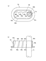
前記凹凸係合部60は、図1および図6に示すように、前記一対の底面カバー部53,53のうち、少なくとも一方の底面カバー部53のスリット53a周縁部に対して設けられるとともに、前記少なくとも一方の支柱1aが係合する複数の凹凸部60a,60bを前記ヘッドレスト本体50の回動方向に沿って連続して形成してなるものである。
すなわち、この凹凸係合部60は、前記底面カバー部53の周壁部53bのスリット53a側面に設けられている。
As shown in FIG. 1 and FIG. 6, the concave and convex engaging portion 60 is provided with respect to the peripheral edge portion of the slit 53 a of at least one bottom surface cover portion 53 of the pair of bottom surface cover portions 53, 53. A plurality of concavo-convex portions 60a and 60b with which at least one of the support pillars 1a is engaged are continuously formed along the rotation direction of the headrest body 50.
That is, the concave and convex engaging portion 60 is provided on the side surface of the slit 53 a of the peripheral wall portion 53 b of the bottom surface cover portion 53.

凹部60bは、前記支柱1aの外周面に合わせて凹む曲面とされており、この曲面は、前記支柱1aの延在方向に連続している。そして、前記支柱1aの延在方向に沿って、この曲面である凹部60bを係合できるようになっている。
また、凹部60bは、図6(b)に示すように複数設けられており、これら複数の凹部60b…は、前記ヘッドレスト本体50の傾斜角度に応じて段階的に傾斜するように配置されている。
凸部60aは、これら複数の凹部60b…間に複数配置されている。また、これら複数の凸部60a…と複数の凹部60b…とは一体形成されている。
The concave portion 60b is a curved surface that is recessed in accordance with the outer peripheral surface of the column 1a, and this curved surface is continuous in the extending direction of the column 1a. And the recessed part 60b which is this curved surface can be engaged now along the extension direction of the said support | pillar 1a.
Further, a plurality of recesses 60b are provided as shown in FIG. 6B, and the plurality of recesses 60b... Are arranged so as to incline stepwise according to the inclination angle of the headrest body 50. .
A plurality of convex portions 60a are arranged between the plurality of concave portions 60b. The plurality of convex portions 60a and the plurality of concave portions 60b are integrally formed.

本実施の形態のクリック機構は、前記ヘッドレスト本体50が前後方向に回動されることにより、前記少なくとも一方の底面カバー部53に設けられた凹凸係合部60が、前記少なくとも一方の支柱1aに対してクリック感を伴いながら移動するように構成されている。すなわち、前記複数の凸部60a…が、前記少なくとも一方の支柱1aを乗り越え、前記凹部60bが、前記少なくとも一方の支柱1aに係合するように設定されている。
また、前記ロック機構によってヘッドレスト本体50の回動にロックがかかる際に、前記複数の凸部60a…が、前記少なくとも一方の支柱1aを乗り越え、前記凹部60bが、前記少なくとも一方の支柱1aに係合するように設定されており、クリック機構とロック機構とを連動させることができる。
以上のようにしてクリック機構が構成されている。また、以上のようにしてヘッドレストが構成されている。
In the click mechanism of the present embodiment, when the headrest body 50 is rotated in the front-rear direction, the concave and convex engaging portion 60 provided on the at least one bottom surface cover portion 53 is attached to the at least one strut 1a. On the other hand, it is configured to move with a click feeling. In other words, the plurality of convex portions 60a... Are set over the at least one strut 1a, and the concave portion 60b is engaged with the at least one strut 1a.
Further, when the rotation of the headrest body 50 is locked by the lock mechanism, the plurality of convex portions 60a ... get over the at least one strut 1a, and the concave portion 60b is engaged with the at least one strut 1a. The click mechanism and the lock mechanism can be interlocked.
The click mechanism is configured as described above. In addition, the headrest is configured as described above.

次に、ヘッドレスト本体50を、ヘッドレストピラー1の横軸部1bに取り付ける方法について説明する。
図1および図2に示すように、前記ヘッドレストピラー1の横軸部1bには、前記ロックブラケット4および取付部2,2が予め取り付けられている。なお、これらロックブラケット4および取付部2,2は、上述のように溶接等により、横軸部1bに対して強固に接合固定されている。
なお、取付前のヘッドレスト本体50には、前記ロック部材22および付勢部材23が取り付けられていない状態となっている。
Next, a method for attaching the headrest body 50 to the horizontal shaft portion 1b of the headrest pillar 1 will be described.
As shown in FIGS. 1 and 2, the lock bracket 4 and the attachment portions 2 and 2 are attached in advance to the horizontal shaft portion 1 b of the headrest pillar 1. The lock bracket 4 and the mounting portions 2 and 2 are firmly bonded and fixed to the horizontal shaft portion 1b by welding or the like as described above.
In addition, the lock member 22 and the urging member 23 are not attached to the headrest body 50 before the attachment.

まず、このようなヘッドレスト本体50を、前記ヘッドレストピラー1の横軸部1bに対して取り付ける。すなわち、ヘッドレスト本体50の下端部に設けられるとともに下方(横軸部1b側)に向かって開放する開放部9aに、前記横軸部1bおよびロックブラケット4を差し込むようにして、ヘッドレスト本体50を横軸部1bに取り付ける。
この時、ロックブラケット4を、前記包囲部8の下端部に形成された差込口8dから包囲部8内部に差し込むようにする。
また、前記開放部9aに差し込まれた横軸部1bは、この開放部9aを含んで構成された把持部9によって把持された状態となる。すなわち、把持部9に備えられた軸受け面9d…によって、前記横軸部1bの長さ方向に沿って該横軸部1bの外周面を受けるようにする。
First, such a headrest body 50 is attached to the horizontal shaft portion 1 b of the headrest pillar 1. That is, the headrest main body 50 is placed in a horizontal direction by inserting the horizontal shaft portion 1b and the lock bracket 4 into an open portion 9a provided at the lower end portion of the headrest main body 50 and opening downward (on the side of the horizontal shaft portion 1b). It is attached to the shaft 1b.
At this time, the lock bracket 4 is inserted into the enclosure portion 8 from an insertion port 8d formed in the lower end portion of the enclosure portion 8.
Further, the horizontal shaft portion 1b inserted into the opening portion 9a is held by the holding portion 9 including the opening portion 9a. That is, the outer peripheral surface of the horizontal shaft portion 1b is received along the length direction of the horizontal shaft portion 1b by the bearing surfaces 9d provided in the grip portion 9.

続いて、ロック部材22を、前記前面壁部51の外側から前面壁部51の内部側に向かって取り付ける。
前記シャフト部22bは、前記抱持部6dのアーチの内側に挿入するとともに、端部を、前記ボタン取付部51c,52c間の空洞内に挿入する。
これと同時に、前記ロックピン部22aを、前記ピン貫通孔21および複数のロック用孔20…のいずれかに差し込むようにする。
また、本実施の形態においては、この段階で、前記ボタン55も取り付けられていない状態となっているが、これに限られるものではなく、前記ロック部材22を、前記前面壁部51の外側から前面壁部51の内部側に向かって取り付けるよりも前の工程で、前記ボタン55および装飾縁部54を、ボタン取付部51cに取り付けておいても良いものとする。
Subsequently, the lock member 22 is attached from the outside of the front wall portion 51 toward the inside of the front wall portion 51.
The shaft portion 22b is inserted inside the arch of the holding portion 6d, and the end portion is inserted into the cavity between the button attachment portions 51c and 52c.
At the same time, the lock pin portion 22a is inserted into either the pin through hole 21 or the plurality of lock holes 20.
In the present embodiment, the button 55 is not attached at this stage. However, the present invention is not limited to this, and the lock member 22 is attached from the outside of the front wall portion 51. The button 55 and the decorative edge portion 54 may be attached to the button attachment portion 51c in a step before attachment toward the inner side of the front wall portion 51.

続いて、コイルバネである付勢部材23を保持部10によって保持する。まず、付勢部材23の連結部22c側端部を、該付勢部材23を圧縮させたり弾性的に屈曲させたりしながら、前記一対の支持部10a,10aと当接部10bとの間に差し込む。また、付勢部材23の、前面壁部51の他側部側端部を、前記引掛部10cに引掛ける。
なお、本実施の形態においては、前記付勢部材23の連結部22c側端部を取り付けてから、前記付勢部材23の、前面壁部51の他側部側端部を取り付ける手順としているが、これに限られるものではなく、前記付勢部材23の、前面壁部51の他側部側端部から取り付けるようにしても良い。また、その他の方法を採用して付勢部材23を取り付けても良く、本発明の趣旨を逸脱しない範囲で適宜変更可能である。
Subsequently, the urging member 23 that is a coil spring is held by the holding unit 10. First, the end of the biasing member 23 on the side of the connecting portion 22c is compressed between the pair of support portions 10a, 10a and the contact portion 10b while compressing or elastically bending the biasing member 23. Plug in. Moreover, the other side part side edge part of the front wall part 51 of the biasing member 23 is hooked on the said hook part 10c.
In the present embodiment, the end of the biasing member 23 on the side of the connecting portion 22c is attached, and then the end of the biasing member 23 on the other side of the front wall 51 is attached. However, the present invention is not limited to this, and the biasing member 23 may be attached from the end portion on the other side portion of the front wall portion 51. Further, the urging member 23 may be attached by adopting other methods, and can be appropriately changed without departing from the gist of the present invention.

続いて、前記横軸部1bに取り付けられた取付部2,2と、前記ヘッドレスト本体50の前面壁部6の背面側に設けられた取付部6f,6fとの間に、前記付勢部材3,3を取り付ける。すなわち、付勢部材3,3の上端部を、前記取付部6f,6fにそれぞれ引掛けるとともに、下端部を、前記取付部2,2にそれぞれ引掛ける。
なお、本実施の形態においては、付勢部材3よりも先に付勢部材23を取り付ける手順を採用したが、これに限られるものではなく、付勢部材3から取り付ける手順を作用しても良いものとする。
Subsequently, the urging member 3 is disposed between the attachment portions 2 and 2 attached to the horizontal shaft portion 1b and the attachment portions 6f and 6f provided on the back side of the front wall portion 6 of the headrest body 50. , 3 is attached. That is, the upper end portions of the urging members 3 and 3 are hooked on the mounting portions 6f and 6f, respectively, and the lower end portions are hooked on the mounting portions 2 and 2, respectively.
In the present embodiment, the procedure for attaching the urging member 23 prior to the urging member 3 is adopted. However, the present invention is not limited to this, and the procedure for attaching from the urging member 3 may be applied. Shall.

その後、前記装飾縁部54およびボタン55も、前記前面壁部51のボタン取付部51cのボタン差込口用切欠部51dに嵌め込んでおく。この時、前記シャフト部22bを、前記付勢部材23が圧縮する方向に移動させながら、該シャフト部22bの端部をボタン55に取り付けるようにする。
そして、前記背面壁部52を、前記前面壁部51に対して結合させるようにする。この時、背面壁部52のボタン取付部52cのボタン差込口用切欠部52dを、前記前面壁部51のボタン取付部51cのボタン差込口用切欠部51dと組み合わせる。これによって、前記装飾縁部54およびボタン55を、ボタン取付部51c,52cに取り付けることができる。
Thereafter, the decorative edge portion 54 and the button 55 are also fitted into the button insertion slot 51 d of the button attachment portion 51 c of the front wall portion 51. At this time, the end portion of the shaft portion 22b is attached to the button 55 while the shaft portion 22b is moved in the direction in which the biasing member 23 is compressed.
Then, the rear wall portion 52 is coupled to the front wall portion 51. At this time, the button insertion port notch portion 52d of the button attachment portion 52c of the rear wall portion 52 is combined with the button insertion portion cutout portion 51d of the button attachment portion 51c of the front wall portion 51. Thereby, the decorative edge portion 54 and the button 55 can be attached to the button attachment portions 51c and 52c.

次に、予め凹凸係合部60が周壁部53bのスリット53a側に設けられた底面カバー部53,53を、前記前面壁部51および背面壁部52の底面部51a,52aに取り付ける。すなわち、2つの差込口用切欠部51bと、2つの差込口用切欠部と52bを組み合わせることで形成された2つの差込口に、前記底面カバー部53,53をそれぞれ差し込んで嵌合する。
また、この時に、底面カバー部53のスリット53aに、前記ヘッドレストピラー1の支柱1aを挿通させるようにする。
以上のようにしてヘッドレスト本体50を、前記ヘッドレストピラー1の横軸部1bに取り付けることができる。
Next, the bottom cover portions 53 and 53 in which the concave and convex engaging portions 60 are provided in advance on the slit 53a side of the peripheral wall portion 53b are attached to the bottom surface portions 51a and 52a of the front wall portion 51 and the back wall portion 52. That is, the bottom cover portions 53 and 53 are respectively inserted and fitted into two insertion ports formed by combining the two insertion port notches 51b and the two insertion port notches 52b. To do.
At this time, the support pillar 1a of the headrest pillar 1 is inserted into the slit 53a of the bottom cover 53.
The headrest body 50 can be attached to the horizontal shaft portion 1b of the headrest pillar 1 as described above.

次に、以上のように構成されたヘッドレストの動作について説明する。
ヘッドレストの動作は、図5に示すように、前記ヘッドレストピラー1の横軸部1bに対して前後方向に回動自在に取り付けられたヘッドレスト本体50の前後方向への回動に基づくものである。
また、ヘッドレスト本体50は、前記付勢部材3,3によって、該ヘッドレスト本体50をヘッドレストピラー1の横軸部1b側に引き寄せる方向に付勢されている。したがって、ヘッドレスト本体50が後方に引き寄せられるとともに、前記ロックピン部22aが、複数のロック用孔20…のうちの最も後方にあるロック用孔20に挿入された状態が、ヘッドレスト本体50の前後方向への回動の通常位置とされている。
Next, the operation of the headrest configured as described above will be described.
As shown in FIG. 5, the operation of the headrest is based on the rotation of the headrest main body 50 attached to the horizontal shaft portion 1 b of the headrest pillar 1 so as to be rotatable in the front-rear direction.
The headrest body 50 is urged by the urging members 3 and 3 in a direction to draw the headrest body 50 toward the horizontal shaft portion 1 b of the headrest pillar 1. Accordingly, the state in which the headrest main body 50 is drawn rearward and the lock pin portion 22a is inserted into the lock hole 20 at the rearmost of the plurality of lock holes 20 is the front-rear direction of the headrest main body 50. This is the normal position for rotation.

ヘッドレスト本体50を前後方向に回動させる際は、前記ロック部材22を操作する。すなわち、前記ロックピン部22aを、ピン貫通孔21を貫通した状態を保持しつつ、先端部をロック用孔20から抜くようにする。これによって、ロックが解除された状態となり、ヘッドレスト本体50を前後方向に回動させることができる。
ロックピン部22aの先端部をロック用孔20から抜く際には、前記シャフト部22bのボタン55が取り付けられる端部を、該シャフト部22bの軸方向に沿って付勢部材23が圧縮する方向に押し込む。これによって、ロックピン部22aの先端部をロック用孔20から抜くことができる。
この時、付勢部材23は保持部10に保持された状態で圧縮する。ボタン55を押し込む操作を止めると、付勢部材23によって連結部22cが押し戻され、これに伴って、ロックピン部22aはロック用孔20に差し込まれる方向に移動し、シャフト部22bも元に戻ろうとする。
When the headrest body 50 is rotated in the front-rear direction, the lock member 22 is operated. That is, the tip end portion is pulled out from the locking hole 20 while the lock pin portion 22a is maintained in the state of passing through the pin through hole 21. Thus, the lock is released and the headrest body 50 can be rotated in the front-rear direction.
A direction in which the biasing member 23 compresses the end portion of the shaft portion 22b to which the button 55 is attached along the axial direction of the shaft portion 22b when the distal end portion of the lock pin portion 22a is pulled out from the locking hole 20. Push into. As a result, the tip of the lock pin portion 22a can be removed from the lock hole 20.
At this time, the urging member 23 is compressed while being held by the holding portion 10. When the operation of pushing the button 55 is stopped, the linking member 22c is pushed back by the urging member 23. Accordingly, the lock pin portion 22a moves in a direction to be inserted into the lock hole 20, and the shaft portion 22b also returns to the original position. I will try.

ロックピン部22aを最後方のロック用孔20から抜き、ヘッドレスト本体50を、通常位置よりも後方に回転させた時には、ヘッドレスト本体50の前面壁部51が、ロックブラケット4の前端4aに当接する。これによって、ヘッドレスト本体50の後方への回転を規制できるようになっている。   When the lock pin portion 22a is removed from the rearmost locking hole 20 and the headrest main body 50 is rotated rearward from the normal position, the front wall portion 51 of the headrest main body 50 contacts the front end 4a of the lock bracket 4. . As a result, the backward rotation of the headrest body 50 can be restricted.

ヘッドレスト本体50を前方に一段階回転させるに際し、ロックピン部22aが最後方のロック用孔20に差し込まれている状態から、二番目に後方に位置するロック用孔20に差し込む場合は、まず、前記シャフト部22bのボタン55が取り付けられた端部を押し込み、ロックピン部22aの先端部を、最後方のロック用孔20から抜く。
続いて、ヘッドレスト本体50を前方へ回転させる。
この時、図6に示すクリック機構の凹凸係合部60の凸部60aが、前記支柱1aを乗り越えて、前記凹部60bが、この支柱1aに係合するように動き、これに伴って、クリック感が生起する。
また、このクリック機構とロック機構は連動しているため、前記凸部60aが支柱1aを乗り越えるのと同時に、ロックピン部22aの先端部は、最後方のロック用孔20と二番目に後方のロック用孔20との間を移動する。さらに、前記凹部60bが支柱1aに係合するのと同時に、ロックピン部22aの先端部は、二番目に後方のロック用孔20に差し込まれることになる。
この時、前記ロック部材22の連結部22cは、前記付勢部材23によって付勢されているため、前記シャフト部22bを操作せずとも、前記ロックピン部22aを付勢部材23の付勢力によって自動的にロック用孔20に差し込むことができる。
When the headrest main body 50 is rotated forward by one step, when the lock pin portion 22a is inserted into the lock hole 20 located at the second rear from the state where the lock pin portion 22a is inserted into the lock hole 20 at the rear end, The end portion of the shaft portion 22b to which the button 55 is attached is pushed in, and the tip end portion of the lock pin portion 22a is pulled out from the rearmost locking hole 20.
Subsequently, the headrest body 50 is rotated forward.
At this time, the convex portion 60a of the concave and convex engaging portion 60 of the click mechanism shown in FIG. 6 moves over the column 1a, and the concave portion 60b moves to engage with the column 1a. A feeling arises.
Further, since the click mechanism and the lock mechanism are interlocked, the tip of the lock pin portion 22a is the second rearward of the locking hole 20 at the same time as the convex portion 60a gets over the column 1a. It moves between the locking holes 20. Further, at the same time when the recess 60b engages with the support 1a, the tip of the lock pin portion 22a is inserted into the rear locking hole 20 second.
At this time, since the connecting portion 22c of the lock member 22 is urged by the urging member 23, the lock pin portion 22a is moved by the urging force of the urging member 23 without operating the shaft portion 22b. It can be automatically inserted into the locking hole 20.

このようにしてヘッドレスト本体50を前方に一段階回転させることができる。
なお、本実施の形態では、ロックピン部22aが最後方のロック用孔20に差し込まれている状態から、二番目に後方に位置するロック用孔20に差し込む場合について説明している。
このような動作は、ロックピン部22aを、二番目に後方のロック用孔20から、三番目に後方のロック用孔20(すなわち、前方から二番目のロック用孔20)に差し込む場合も同様であり、この三番目に後方のロック用孔20から、最前方のロック用孔20に差し込む場合も同様である。
In this way, the headrest body 50 can be rotated forward by one step.
In the present embodiment, the case where the lock pin portion 22a is inserted into the lock hole 20 located second rearward from the state in which the lock pin portion 22a is inserted into the rearmost lock hole 20 is described.
Such an operation is the same when the lock pin portion 22a is inserted from the second rear locking hole 20 into the third rear locking hole 20 (that is, the second locking hole 20 from the front). The same applies to the case where the third locking hole 20 is inserted into the foremost locking hole 20.

ロックピン部22aを最前方のロック用孔20から抜き、ヘッドレスト本体50を、より前方に回転させた時には、ヘッドレスト本体50の後側のストッパー部8c,8cが、ロックブラケット4の後端4bに当接する。これによって、ヘッドレスト本体50の前方への回転を規制できるようになっている。   When the lock pin portion 22a is removed from the foremost locking hole 20 and the headrest body 50 is rotated further forward, the stopper portions 8c, 8c on the rear side of the headrest body 50 are located on the rear end 4b of the lock bracket 4. Abut. As a result, the forward rotation of the headrest body 50 can be restricted.

一方、ヘッドレスト本体50を後方に一段階回転させるに際し、ロックピン部22aが最前方のロック用孔20に差し込まれている状態から、二番目に前方に位置するロック用孔20に差し込む場合は、まず、前記シャフト部22bのボタン55が取り付けられた端部を押し込み、ロックピン部22aの先端部を、最前方のロック用孔20から抜く。
続いて、ヘッドレスト本体50を後方へ回転させる。
この時、図6に示すクリック機構の凹凸係合部60の凸部60aが、前記支柱1aを乗り越えて、前記凹部60bが、この支柱1aに係合するように動き、これに伴って、クリック感が生起する。
また、このクリック機構とロック機構は連動しているため、前記凸部60aが支柱1aを乗り越えるのと同時に、ロックピン部22aの先端部は、最前方のロック用孔20と二番目に前方のロック用孔20との間を移動する。さらに、前記凹部60bが支柱1aに係合するのと同時に、ロックピン部22aの先端部は、二番目に前方のロック用孔20に差し込まれることになる。
この時、前記ロック部材22の連結部22cは、前記付勢部材23によって付勢されているため、前記シャフト部22bを操作せずとも、前記ロックピン部22aを付勢部材23の付勢力によって自動的にロック用孔20に差し込むことができる。
On the other hand, when the headrest body 50 is rotated backward by one step, when the lock pin portion 22a is inserted into the foremost lock hole 20 from the state where the lock pin portion 22a is inserted into the foremost lock hole 20, First, the end portion of the shaft portion 22b to which the button 55 is attached is pushed in, and the tip end portion of the lock pin portion 22a is removed from the foremost locking hole 20.
Subsequently, the headrest body 50 is rotated backward.
At this time, the convex portion 60a of the concave and convex engaging portion 60 of the click mechanism shown in FIG. 6 moves over the column 1a, and the concave portion 60b moves to engage with the column 1a. A feeling arises.
In addition, since the click mechanism and the lock mechanism are interlocked, the tip of the lock pin portion 22a is located at the second front of the locking hole 20 at the same time as the convex portion 60a gets over the column 1a. It moves between the locking holes 20. Further, at the same time when the recess 60b engages with the support 1a, the tip of the lock pin portion 22a is inserted into the front locking hole 20 second.
At this time, since the connecting portion 22c of the lock member 22 is urged by the urging member 23, the lock pin portion 22a is moved by the urging force of the urging member 23 without operating the shaft portion 22b. It can be automatically inserted into the locking hole 20.

このようにしてヘッドレスト本体50を後方に一段階回転させることができる。
なお、本実施の形態では、ロックピン部22aが最前方のロック用孔20に差し込まれている状態から、二番目に前方に位置するロック用孔20に差し込む場合について説明している。
このような動作は、ロックピン部22aを、二番目に前方のロック用孔20から、三番目に前方のロック用孔20(すなわち、後方から二番目のロック用孔20)に差し込む場合も同様であり、この三番目に前方のロック用孔20から、最後方のロック用孔20に差し込む場合も同様である。
以上のようにして、ヘッドレスト本体50を前後方向に回動操作して、ヘッドレストを動作させることができる。
In this way, the headrest body 50 can be rotated backward by one step.
In the present embodiment, the case where the lock pin portion 22a is inserted into the lock hole 20 positioned second forward from the state where the lock pin portion 22a is inserted into the foremost lock hole 20 is described.
Such an operation is the same when the lock pin portion 22a is inserted from the second front locking hole 20 into the third front locking hole 20 (that is, the second locking hole 20 from the rear). The same applies to the case where the third locking hole 20 is inserted from the third front locking hole 20 into the rearmost locking hole 20.
As described above, the headrest body 50 can be rotated in the front-rear direction to operate the headrest.

本実施の形態によれば、クリック機構は、前記前後方向に回動するヘッドレスト本体50と、このヘッドレスト本体50に対して固定状態にあるヘッドレストピラー1の少なくとも一方の支柱1aとの間に設けられることになる。
したがって、前記ヘッドレスト本体50を前後方向に回動させることによって、前記凹凸係合部60の複数の凸部60a…が、少なくとも一方の支柱1aを乗り越え、前記凹部60bが、少なくとも一方の支柱1aに係合するように動くことになるので、クリック感が生起することになる。そして、前記ヘッドレスト本体50を前後方向に回動させる際にクリック感を得ることができるので、クリック機構とロック機構とを連動させることにより、前記ヘッドレスト本体50の操作性を向上させることができる。これによって、前記ロックブラケット4に対するヘッドレスト本体50の傾斜角度を精度良く調整することが可能となる。
According to the present embodiment, the click mechanism is provided between the headrest body 50 that rotates in the front-rear direction and at least one column 1 a of the headrest pillar 1 that is fixed to the headrest body 50. It will be.
Therefore, by rotating the headrest body 50 in the front-rear direction, the plurality of convex portions 60a of the concave-convex engaging portion 60 get over at least one strut 1a, and the concave portion 60b becomes at least one strut 1a. Since it moves so that it may engage, a click feeling will arise. Since a click feeling can be obtained when the headrest body 50 is rotated in the front-rear direction, the operability of the headrest body 50 can be improved by interlocking the click mechanism with the lock mechanism. Thereby, the inclination angle of the headrest body 50 with respect to the lock bracket 4 can be adjusted with high accuracy.

また、ロック機構によってヘッドレスト本体50の回動にロックがかかる際に、前記凹凸係合部60の複数の凸部60a…が、少なくとも一方の支柱1aを乗り越え、前記凹部60bが、少なくとも一方の支柱1aに係合するように設定されているので、クリック機構とロック機構とを連動させることができる。これによって、前記ヘッドレスト本体50を回動させてクリック感が生起した際に、同時にロック機構によってヘッドレスト本体50の回動にロックがかかることになるので、前記ヘッドレスト本体50の操作性を向上させることができる。これによって、前記ロックブラケット4に対するヘッドレスト本体50の傾斜角度を確実かつ精度良く調整することが可能となる。   Further, when the rotation of the headrest body 50 is locked by the lock mechanism, the plurality of convex portions 60a... Of the concave / convex engaging portion 60 get over at least one strut 1a, and the concave portion 60b is at least one strut. Since it is set to engage with 1a, the click mechanism and the lock mechanism can be interlocked. Accordingly, when the headrest body 50 is rotated and a click feeling is generated, the rotation of the headrest body 50 is simultaneously locked by the lock mechanism, so that the operability of the headrest body 50 is improved. Can do. This makes it possible to adjust the inclination angle of the headrest body 50 with respect to the lock bracket 4 reliably and accurately.

1 ヘッドレストピラー
1a 支柱
1b 横軸部
3 付勢部材
4 ロックブラケット
8 包囲部
9 把持部
10 保持部
20 ロック用孔
21 ピン貫通孔
22 ロック部材
22a ロックピン部
22b シャフト部
22c 連結部
23 付勢部材
50 ヘッドレスト本体
51 前面壁部
51a 底面部
51b 差込口用切欠部
52 背面壁部
52a 底面部
52b 差込口用切欠部
53 底面カバー部
53a スリット
53b 周壁部
53c 鍔部
60 凹凸係合部
60a 凸部
60b 凹部
DESCRIPTION OF SYMBOLS 1 Headrest pillar 1a Support | pillar 1b Horizontal shaft part 3 Energizing member 4 Lock bracket 8 Surrounding part 9 Holding part 10 Holding part 20 Locking hole 21 Pin through-hole 22 Lock member 22a Lock pin part 22b Shaft part 22c Connecting part 23 Energizing member 50 Headrest Main Body 51 Front Wall 51a Bottom 51b Insertion Notch 52 Rear Wall 52a Bottom 52b Insertion Notch 53 Bottom Cover 53a Slit 53b Perimeter Wall 53c Ridge 60 Uneven Engagement 60a Convex Part 60b recess

Claims (2)

一対の支柱と、これら一対の支柱の上端部間に架設される横軸部とを有するヘッドレストピラーと、
前記横軸部に、前方に傾斜して固定されるロックブラケットと、
前記横軸部に対して前後方向に回動自在に取り付けられるヘッドレスト本体と、
前記ヘッドレスト本体を、前記ロックブラケットに対して複数の傾斜角度でロックするロック機構と、
前記ヘッドレスト本体の回動に伴ってクリック感を生起するクリック機構と、を備えており、
前記ヘッドレスト本体は、乗員の頭部を受ける前面壁部と、
前記前面壁部の背面側に結合される背面壁部と、
互いに結合された状態の前記前面壁部と背面壁部との底面部に、前記ヘッドレストピラーの一対の支柱の位置に対応して設けられるとともに、該支柱が挿通されるスリットが形成された一対の底面カバー部と、を有しており、
前記クリック機構は、前記一対の支柱のうちの少なくとも一方の支柱と、
前記一対の底面カバー部のうち、少なくとも一方の底面カバー部のスリット周縁部に対して設けられるとともに、前記少なくとも一方の支柱が係合する複数の凹凸部を前記ヘッドレスト本体の回動方向に沿って連続して形成してなる凹凸係合部と、を有していることを特徴とするヘッドレスト。
A headrest pillar having a pair of struts and a horizontal shaft portion constructed between upper ends of the pair of struts;
A lock bracket fixed to the horizontal shaft portion by being inclined forward,
A headrest body attached to the horizontal shaft portion so as to be rotatable in the front-rear direction;
A lock mechanism for locking the headrest body at a plurality of inclination angles with respect to the lock bracket;
A click mechanism that causes a click feeling with the rotation of the headrest body,
The headrest body includes a front wall portion that receives the head of an occupant;
A back wall coupled to the back side of the front wall;
A pair of slits are formed on the bottom surfaces of the front wall portion and the back wall portion in a state of being coupled to each other, corresponding to the positions of the pair of pillars of the headrest pillar and through which the pillars are inserted. And a bottom cover part,
The click mechanism includes at least one strut of the pair of struts;
Among the pair of bottom surface cover portions, a plurality of concave and convex portions that are provided with respect to the slit peripheral edge portion of at least one bottom surface cover portion and that engage with the at least one column are arranged along the rotation direction of the headrest body. A headrest comprising a concavo-convex engaging portion formed continuously.
前記クリック機構は、前記ロック機構によってヘッドレスト本体の回動にロックがかかる際に、前記凹凸係合部の複数の凸部が、前記少なくとも一方の支柱を乗り越え、凹部が、前記少なくとも一方の支柱に係合するように設定されていることを特徴とする請求項1に記載のヘッドレスト。   In the click mechanism, when the rotation of the headrest main body is locked by the lock mechanism, the plurality of convex portions of the concave and convex engaging portion get over the at least one post, and the concave portion is on the at least one post. The headrest according to claim 1, wherein the headrest is set to be engaged.
JP2011065695A 2011-03-24 2011-03-24 Headrest Active JP5797434B2 (en)

Priority Applications (1)

Application Number Priority Date Filing Date Title
JP2011065695A JP5797434B2 (en) 2011-03-24 2011-03-24 Headrest

Applications Claiming Priority (1)

Application Number Priority Date Filing Date Title
JP2011065695A JP5797434B2 (en) 2011-03-24 2011-03-24 Headrest

Publications (2)

Publication Number Publication Date
JP2012201152A true JP2012201152A (en) 2012-10-22
JP5797434B2 JP5797434B2 (en) 2015-10-21

Family

ID=47182586

Family Applications (1)

Application Number Title Priority Date Filing Date
JP2011065695A Active JP5797434B2 (en) 2011-03-24 2011-03-24 Headrest

Country Status (1)

Country Link
JP (1) JP5797434B2 (en)

Cited By (2)

* Cited by examiner, † Cited by third party
Publication number Priority date Publication date Assignee Title
EP2930055A4 (en) * 2012-12-04 2016-08-31 Ts Tech Co Ltd Headrest
JP2016164029A (en) * 2015-03-06 2016-09-08 株式会社タチエス Head rest

Citations (10)

* Cited by examiner, † Cited by third party
Publication number Priority date Publication date Assignee Title
JPS468977Y1 (en) * 1969-08-15 1971-03-31
JPS63169953U (en) * 1987-04-25 1988-11-04
JPH01104249U (en) * 1987-12-29 1989-07-13
JPH0593296U (en) * 1992-05-25 1993-12-21 日産ディーゼル工業株式会社 Headrest device for vehicle seat
JPH09140505A (en) * 1995-11-28 1997-06-03 Inoac Corp Headrest for automobile
JPH1080335A (en) * 1996-09-10 1998-03-31 Delta Kogyo Co Ltd Swing structure for headrest
JP2001238753A (en) * 2000-02-29 2001-09-04 Aisin Seiki Co Ltd Headrest device
FR2806678A1 (en) * 2000-03-23 2001-09-28 Faure Bertrand Equipements Sa Headrest has an internal structure pivoting on the top end of the rigid rod from the back seat and a resisting element exerting a higher resisting torque when the headrest is forced backwards than when it is forced forwards
JP2001275781A (en) * 2000-03-30 2001-10-09 Aisin Seiki Co Ltd Headrest device
US20070164593A1 (en) * 2006-01-17 2007-07-19 Windsor Machine & Stamping Limited Articulating headrest assembly

Patent Citations (10)

* Cited by examiner, † Cited by third party
Publication number Priority date Publication date Assignee Title
JPS468977Y1 (en) * 1969-08-15 1971-03-31
JPS63169953U (en) * 1987-04-25 1988-11-04
JPH01104249U (en) * 1987-12-29 1989-07-13
JPH0593296U (en) * 1992-05-25 1993-12-21 日産ディーゼル工業株式会社 Headrest device for vehicle seat
JPH09140505A (en) * 1995-11-28 1997-06-03 Inoac Corp Headrest for automobile
JPH1080335A (en) * 1996-09-10 1998-03-31 Delta Kogyo Co Ltd Swing structure for headrest
JP2001238753A (en) * 2000-02-29 2001-09-04 Aisin Seiki Co Ltd Headrest device
FR2806678A1 (en) * 2000-03-23 2001-09-28 Faure Bertrand Equipements Sa Headrest has an internal structure pivoting on the top end of the rigid rod from the back seat and a resisting element exerting a higher resisting torque when the headrest is forced backwards than when it is forced forwards
JP2001275781A (en) * 2000-03-30 2001-10-09 Aisin Seiki Co Ltd Headrest device
US20070164593A1 (en) * 2006-01-17 2007-07-19 Windsor Machine & Stamping Limited Articulating headrest assembly

Cited By (4)

* Cited by examiner, † Cited by third party
Publication number Priority date Publication date Assignee Title
EP2930055A4 (en) * 2012-12-04 2016-08-31 Ts Tech Co Ltd Headrest
US9487115B2 (en) 2012-12-04 2016-11-08 Ts Tech Co., Ltd. Headrest having a recess on a bottom thereof and facing the head of a headrest guide
JP2016164029A (en) * 2015-03-06 2016-09-08 株式会社タチエス Head rest
US10245989B2 (en) 2015-03-06 2019-04-02 Tachi-S Co., Ltd. Headrest

Also Published As

Publication number Publication date
JP5797434B2 (en) 2015-10-21

Similar Documents

Publication Publication Date Title
JP6038938B2 (en) Headrest
JP6068509B2 (en) Headrest
WO2014049723A1 (en) Head rest
JP6055836B2 (en) Headrest
JP6038939B2 (en) Headrest
JPWO2014103044A1 (en) Headrest
JPWO2014049726A1 (en) Headrest
JP5797434B2 (en) Headrest
JP6069371B2 (en) Headrest
WO2010010748A1 (en) Headrest
JP5797433B2 (en) Headrest
JP6069370B2 (en) Headrest
JP6069372B2 (en) Headrest
JP5872718B2 (en) Headrest
JP5677880B2 (en) Headrest
JP5677877B2 (en) Headrest
JP5677878B2 (en) Headrest
JP5677879B2 (en) Headrest
JP6298876B2 (en) Headrest
JP6522729B2 (en) Headrest
JP2013123971A (en) Operation lever of seat slide device
JP6214707B2 (en) Headrest
JP5824304B2 (en) Chair
JP6654172B2 (en) Vehicle seat
JP6481000B2 (en) Headrest

Legal Events

Date Code Title Description
A621 Written request for application examination

Free format text: JAPANESE INTERMEDIATE CODE: A621

Effective date: 20140320

A131 Notification of reasons for refusal

Free format text: JAPANESE INTERMEDIATE CODE: A131

Effective date: 20141202

A521 Request for written amendment filed

Free format text: JAPANESE INTERMEDIATE CODE: A523

Effective date: 20150127

TRDD Decision of grant or rejection written
A01 Written decision to grant a patent or to grant a registration (utility model)

Free format text: JAPANESE INTERMEDIATE CODE: A01

Effective date: 20150804

A61 First payment of annual fees (during grant procedure)

Free format text: JAPANESE INTERMEDIATE CODE: A61

Effective date: 20150819

R150 Certificate of patent or registration of utility model

Ref document number: 5797434

Country of ref document: JP

Free format text: JAPANESE INTERMEDIATE CODE: R150

R250 Receipt of annual fees

Free format text: JAPANESE INTERMEDIATE CODE: R250

R250 Receipt of annual fees

Free format text: JAPANESE INTERMEDIATE CODE: R250

R250 Receipt of annual fees

Free format text: JAPANESE INTERMEDIATE CODE: R250

R250 Receipt of annual fees

Free format text: JAPANESE INTERMEDIATE CODE: R250

R250 Receipt of annual fees

Free format text: JAPANESE INTERMEDIATE CODE: R250

R250 Receipt of annual fees

Free format text: JAPANESE INTERMEDIATE CODE: R250

R250 Receipt of annual fees

Free format text: JAPANESE INTERMEDIATE CODE: R250