JP2012199057A - Table tap warning system, table tap with warning function, and auxiliary plug - Google Patents
Table tap warning system, table tap with warning function, and auxiliary plug Download PDFInfo
- Publication number
- JP2012199057A JP2012199057A JP2011062126A JP2011062126A JP2012199057A JP 2012199057 A JP2012199057 A JP 2012199057A JP 2011062126 A JP2011062126 A JP 2011062126A JP 2011062126 A JP2011062126 A JP 2011062126A JP 2012199057 A JP2012199057 A JP 2012199057A
- Authority
- JP
- Japan
- Prior art keywords
- configuration information
- power consumption
- multiplicity
- table tap
- wiring
- Prior art date
- Legal status (The legal status is an assumption and is not a legal conclusion. Google has not performed a legal analysis and makes no representation as to the accuracy of the status listed.)
- Withdrawn
Links
Images

Landscapes
- Details Of Connecting Devices For Male And Female Coupling (AREA)
Abstract
【課題】テーブルタップについて使用電力量の警告およびたこ足配線の警告を行う。
【解決手段】警告機能付きテーブルタップ111の使用電力測定部120は、コンセント口121毎に使用電力量を測定する。記憶部119は、コンセント口121に接続されている機器の過去の最大電力使用量等を記憶する。送受信部115は、配線接続ネットワーク表示端末101から構成情報の送信命令を受信すると、その送信命令に付加されている多重度情報に基づいてコンセント口121毎にたこ足配線の多重度を求め、現在の使用電力量と最大電力使用量とたこ足配線の多重度とを含む構成情報をPLCモデム117により送信する。配線接続ネットワーク表示端末101の送受信部104は、送信された構成情報をPLCモデム105により受信する。データ処理部103は、受信された構成情報に基づいて警告情報を作成する。表示部102は、作成された警告情報を表示する。
【選択図】図1A power tap warning and a octopus wiring warning for a table tap are provided.
A power consumption measuring unit of a table tap with a warning function measures a power consumption for each outlet port. The storage unit 119 stores the past maximum power usage amount of the device connected to the outlet port 121. When receiving the configuration information transmission command from the wiring connection network display terminal 101, the transmission / reception unit 115 obtains the multiplicity of the tachometer wiring for each outlet port 121 based on the multiplicity information added to the transmission command. The PLC modem 117 transmits the configuration information including the power usage amount, the maximum power usage amount, and the multiplicity of the octopus wiring. The transmission / reception unit 104 of the wired connection network display terminal 101 receives the transmitted configuration information by the PLC modem 105. The data processing unit 103 creates warning information based on the received configuration information. The display unit 102 displays the created warning information.
[Selection] Figure 1
Description
本発明は、テーブルタップにおける消費電力量及び多重配線状態の警告を行うテーブルタップ警告システム、警告機能付きテーブルタップおよび補助プラグに関する。 The present invention relates to a table tap warning system, a table tap with a warning function, and an auxiliary plug that perform warning of power consumption and multiple wiring states in a table tap.
電気機器の利便性の良い配置、配線の管理を行うために、電力コードの延長や配線の集中は必要不可欠であり、これを実現するためにテーブルタップが用いられている。
また、近年の地球温暖化や環境問題への意識の高まりから、エコ活動、省エネ活動が活発となってきており、無駄な電力を意識的にカットすることが叫ばれる様になっている。
In order to perform convenient arrangement and wiring management of electric devices, extension of power cords and concentration of wiring are indispensable, and table taps are used to realize this.
In recent years, with increasing awareness of global warming and environmental issues, eco- and energy-saving activities have become active, and it has been called out to cut wasteful power consciously.
この省エネ活動を支援するために、スイッチの状態をONからOFFに切り替えることで通電を遮断し、待機電力をカットできるスイッチ付きテーブルタップを用いることができる。スイッチ付きテーブルタップには、テーブルタップ全体で1つのスイッチが付いているものや、コンセント口毎にスイッチが付いているもの、またはそれら両種のスイッチが付いているものがある(例えば、特許文献1参照)。例えば、コンセント口毎にスイッチが付いているテーブルタップでは、各スイッチの状態をONからOFFに切り替えることで対象となるコンセント口の通電状態を個別に変更することができる。
このようなスイッチ付きテーブルタップでは、スイッチのON/OFFの切り替えにより使用電力量削減を実施することが可能である。
In order to support this energy saving activity, it is possible to use a table tap with a switch that can cut off standby power by cutting off the energization by switching the switch state from ON to OFF. Some table taps with a switch have one switch for the entire table tap, some have a switch for each outlet, or some have both types of switches (for example, Patent Documents). 1). For example, in a table tap having a switch for each outlet port, the energization state of the target outlet port can be individually changed by switching the state of each switch from ON to OFF.
In such a table tap with a switch, it is possible to reduce the amount of power used by switching the switch ON / OFF.
しかし、従来のスイッチ付きテーブルタップでは、使用電力量が視覚的に分からないため、スイッチのON/OFFは管理者主導による部分が大きかった。
また、従来のスイッチ付きテーブルタップでは、テーブルタップにテーブルタップを繋ぐと言った多重度を上げたたこ足配線における危険性や、その危険部位を知ることはできなかった。
However, in the conventional table tap with a switch, the amount of power used is not visually understood, and therefore, the switch ON / OFF is largely driven by the administrator.
In addition, in the conventional table tap with a switch, it has not been possible to know the danger and the dangerous part in the tako-foot wiring with increased multiplicity such as connecting the table tap to the table tap.
本発明の目的は、テーブルタップについて使用電力量の警告および多重度を上げたたこ足配線の警告を行うことができるテーブルタップ警告システム、警告機能付きテーブルタップおよび補助プラグを提供することである。 An object of the present invention is to provide a table tap warning system, a table tap with a warning function, and an auxiliary plug that can issue a warning of power consumption and a warning of takotsu wire with increased multiplicity for the table tap.
上記目的を達成するため、本発明のテーブルタップ警告システムは、
警告機能付きテーブルタップと、配線接続ネットワーク表示端末とを有するテーブルタップ警告システムであって、
前記警告機能付きテーブルタップが、
複数のコンセント口と、
電気配線を利用してデータ通信を行う第1のPLCモデムと、
前記コンセント口毎に、使用電力量を測定する第1の使用電力量測定手段と、
前記コンセント口毎に、前記第1の使用電力量測定手段によって過去に測定された最大の使用電力量である最大電力使用量を記憶する最大電力使用量記憶手段と、
前記コンセント口毎に、たこ足配線の多重度を求める第1の多重度取得手段と、
前記第1の使用電力量測定手段によって測定された現在の使用電力量と、前記最大電力使用量記憶手段に記憶されている最大電力使用量と、前記第1の多重度取得手段によって求められたたこ足配線の多重度とを含む第1の構成情報を前記第1のPLCモデムにより送信する第1の構成情報送信手段と、
を備え、
前記配線接続ネットワーク表示端末が、
電気配線を利用してデータ通信を行う第2のPLCモデムと、
前記警告機能付きテーブルタップから送信された前記第1の構成情報を前記第2のPLCモデムにより受信する第1の構成情報受信手段と、
前記第1の構成情報受信手段によって受信された第1の構成情報に含まれる現在の使用電力量と最大電力使用量とたこ足配線の多重度とに基づいて所定の警告情報を作成する警告情報作成手段と、
前記警告情報作成手段によって作成された警告情報を表示する表示手段と、
を備える。
In order to achieve the above object, the table tap warning system of the present invention includes:
A table tap warning system having a table tap with a warning function and a wired connection network display terminal,
The table tap with warning function is
Multiple outlets,
A first PLC modem for performing data communication using electrical wiring;
First power consumption measuring means for measuring the power consumption for each outlet port;
Maximum power usage storage means for storing maximum power usage, which is the maximum power consumption measured in the past by the first power usage measurement means, for each outlet port;
First multiplicity acquisition means for determining the multiplicity of the octopus wiring for each outlet port;
The current power consumption measured by the first power consumption measuring unit, the maximum power usage stored in the maximum power usage storage unit, and the first multiplicity acquisition unit. First configuration information transmitting means for transmitting first configuration information including the multiplicity of the tactile wiring by the first PLC modem;
With
The wired connection network display terminal is
A second PLC modem for data communication using electrical wiring;
First configuration information receiving means for receiving the first configuration information transmitted from the table tap with warning function by the second PLC modem;
Warning information for creating predetermined warning information based on the current power consumption, the maximum power usage, and the multiplicity of the octopus wiring included in the first configuration information received by the first configuration information receiving means Creating means;
Display means for displaying the warning information created by the warning information creating means;
Is provided.
好ましくは、本発明のテーブルタップ警告システムは、
前記第1の使用電力量測定手段と前記第1の多重度取得手段とを有していないテーブルタップのコンセント口に接続される補助プラグを備え、
前記補助プラグが、
補助コンセント口と、
電気配線を利用してデータ通信を行う第3のPLCモデムと、
前記補助コンセント口における使用電力量を測定する第2の使用電力量測定手段と、
当該補助プラグにおけるたこ足配線の多重度を求める第2の多重度取得手段と、
前記第2の使用電力量測定手段によって測定された現在の使用電力量と、前記第2の多重度取得手段によって求められたたこ足配線の多重度とを含む第2の構成情報を前記第3のPLCモデムにより送信する第2の構成情報送信手段と、
を有し、
前記警告機能付きテーブルタップは、
前記補助プラグの第2の構成情報送信手段によって送信される第2の構成情報を前記第1のPLCモデムにより受信する第2の構成情報受信手段を備え、
前記第1の構成情報送信手段が、前記第1の構成情報とともに前記第2の構成情報受信手段によって受信された第2の構成情報を送信し、
前記配線接続ネットワーク表示端末は、
前記第1の構成情報受信手段が、前記第1の構成情報とともに前記第2の構成情報を受信し、
前記警告情報作成手段が、前記第1の構成情報に含まれる現在の使用電力量と最大電力使用量とたこ足配線の多重度および前記第2の構成情報に含まれる現在の使用電力量とたこ足配線の多重度に基づいて所定の警告情報を作成する、
ことを特徴とする請求項1に記載のテーブルタップ警告システム。
Preferably, the table tap warning system of the present invention includes:
An auxiliary plug connected to an outlet of a table tap that does not have the first power consumption measuring unit and the first multiplicity acquisition unit;
The auxiliary plug is
An auxiliary outlet,
A third PLC modem for data communication using electrical wiring;
Second power consumption measuring means for measuring the power consumption at the auxiliary outlet,
A second multiplicity acquisition means for determining the multiplicity of the octopus wiring in the auxiliary plug;
The second configuration information including the current power consumption measured by the second power consumption measuring unit and the multiplicity of the octopus wiring obtained by the second multiplicity acquisition unit is the third configuration information. Second configuration information transmitting means for transmitting by the PLC modem of
Have
The table tap with warning function is
Second configuration information receiving means for receiving, by the first PLC modem, second configuration information transmitted by the second configuration information transmitting means of the auxiliary plug;
The first configuration information transmitting means transmits the second configuration information received by the second configuration information receiving means together with the first configuration information;
The wire connection network display terminal is
The first configuration information receiving means receives the second configuration information together with the first configuration information;
The warning information creating means includes a current power consumption amount and a maximum power usage amount included in the first configuration information, a multiplicity of tachometer wiring, and a current power consumption amount and a tako included in the second configuration information. Create predetermined warning information based on multiplicity of foot wiring,
The table tap warning system according to
また、本発明の警告機能付きテーブルタップは、
警告機能付きテーブルタップと、配線接続ネットワーク表示端末とを有するテーブルタップ警告システムで用いられる警告機能付きテーブルタップであって、
複数のコンセント口と、
電気配線を利用してデータ通信を行う第1のPLCモデムと、
前記コンセント口毎に、使用電力量を測定する第1の使用電力量測定手段と、
前記コンセント口毎に、前記第1の使用電力量測定手段によって過去に測定された最大の使用電力量である最大電力使用量を記憶する最大電力使用量記憶手段と、
前記コンセント口毎に、たこ足配線の多重度を求める第1の多重度取得手段と、
前記第1の使用電力量測定手段によって測定された現在の使用電力量と、前記最大電力使用量記憶手段に記憶されている最大電力使用量と、前記第1の多重度取得手段によって求められたたこ足配線の多重度とを含む第1の構成情報を前記第1のPLCモデムにより送信する第1の構成情報送信手段と、
を備える。
Moreover, the table tap with a warning function of the present invention is
A table tap with a warning function used in a table tap warning system having a table tap with a warning function and a wired connection network display terminal,
Multiple outlets,
A first PLC modem for performing data communication using electrical wiring;
First power consumption measuring means for measuring the power consumption for each outlet port;
Maximum power usage storage means for storing maximum power usage, which is the maximum power consumption measured in the past by the first power usage measurement means, for each outlet port;
First multiplicity acquisition means for determining the multiplicity of the octopus wiring for each outlet port;
The current power consumption measured by the first power consumption measuring unit, the maximum power usage stored in the maximum power usage storage unit, and the first multiplicity acquisition unit. First configuration information transmitting means for transmitting first configuration information including the multiplicity of the tactile wiring by the first PLC modem;
Is provided.
また、本発明の補助プラグは、
警告機能付きテーブルタップと、配線接続ネットワーク表示端末と、補助プラグとを有するテーブルタップ警告システムで用いられ、テーブルタップのコンセント口に接続される補助プラグであって、
補助コンセント口と、
電気配線を利用してデータ通信を行う第3のPLCモデムと、
前記補助コンセント口における使用電力量を測定する第2の使用電力量測定手段と、
当該補助プラグにおけるたこ足配線の多重度を求める第2の多重度取得手段と、
前記第2の使用電力量測定手段によって測定された現在の使用電力量と、前記第2の多重度取得手段によって求められたたこ足配線の多重度とを含む第2の構成情報を前記第3のPLCモデムにより送信する第2の構成情報送信手段と、
を備える。
The auxiliary plug of the present invention is
An auxiliary plug used in a table tap warning system having a table tap with a warning function, a wiring connection network display terminal, and an auxiliary plug, and connected to the outlet of the table tap,
An auxiliary outlet,
A third PLC modem for data communication using electrical wiring;
Second power consumption measuring means for measuring the power consumption at the auxiliary outlet,
A second multiplicity acquisition means for determining the multiplicity of the octopus wiring in the auxiliary plug;
The second configuration information including the current power consumption measured by the second power consumption measuring unit and the multiplicity of the octopus wiring obtained by the second multiplicity acquisition unit is the third configuration information. Second configuration information transmitting means for transmitting by the PLC modem of
Is provided.
本発明によれば、テーブルタップについて使用電力量の警告および多重度を上げたたこ足配線の警告を行うことができる。 ADVANTAGE OF THE INVENTION According to this invention, the warning of the electric power consumption about a table tap and the warning of the tucking-up wiring which raised multiplicity can be performed.
本発明の実施形態に係るテーブルタップ警告システムについて、図面を参照しながら以下に詳細に説明する。
図1は、本発明の実施形態に係るテーブルタップ警告システムの構成の一例を示す。
本発明の実施形態に係るテーブルタップ警告システムは、配線接続ネットワーク表示端末101と、警告機能付きテーブルタップ111と、補助プラグ123とで構成される。
図1において、配線接続ネットワーク表示端末101には、警告機能付きテーブルタップ111が接続されている。警告機能付きテーブルタップ111には機器A131および既存のテーブルタップ128が接続されており、既存のテーブルタップ128には補助プラグ123が接続され、補助プラグ123に機器B133が接続されている。
A table tap warning system according to an embodiment of the present invention will be described in detail below with reference to the drawings.
FIG. 1 shows an example of the configuration of a table tap warning system according to an embodiment of the present invention.
The table tap warning system according to the embodiment of the present invention includes a wired connection
In FIG. 1, a
従って、図1は、配線接続ネットワーク表示端末101の配下に、警告機能付きテーブルタップ111と、機器A131と、既存のテーブルタップ128と、補助プラグ123と、機器B133とが接続された1つの配線ネットワークが形成されている状態を示す。
例えば、警告機能付きテーブルタップ111にテレビや電気ポットおよび既存のテーブルタップが接続され、既存のテーブルタップに更に携帯の充電器やPCの電源が接続されているような配線接続ネットワークがある。
Accordingly, FIG. 1 shows one wiring in which the
For example, there is a wiring connection network in which a TV, an electric pot, and an existing table tap are connected to the
配線接続ネットワーク表示端末101は、表示部102と、データ処理部103と、送受信部104と、PLC(Power Line Communictions)モデム105と、表示処理部106と、操作部107と、起動スイッチ108と、コンセント口109と、接続プラグ110とで構成されている。
表示部102は、配線接続ネットワーク表示端末101の配下に形成された配線接続ネットワークのネットワーク図と所定の警告を表示する。
表示処理部106は、表示部102の表示処理を実施する。
データ処理部103は、RAM(Random Access Memory)等で構成されるメモリを含み、表示部102に表示するためのデータを処理する。データ処理部103は、配線接続ネットワーク図を作成・更新する。また、データ処理部103は、配下の警告機能付きテーブルタップ111と補助プラグ123から受信したたこ足配線の多重度、最大電力使用量及び現在使用中の使用電力量等を含む構成情報をメモリに記憶する。そして、データ処理部103は、メモリに記憶されている構成情報を利用し、多重接続が3重以上になっている箇所や最大電力使用量の合計値が警告機能付きテーブルタップ111の供給電力量を超える箇所、現在使用中の電力量が警告機能付きテーブルタップ111の供給電力量を超える箇所等の判定を行い、危険部位を特定して警告情報の表示処理を表示処理部106に実行させる。
送受信部104は、配下の警告機能付きテーブルタップ111および補助プラグ123と情報のやり取りを行う。
PLCモデム105は、電力線を通信経路として利用するための変換機としての役割を持つ。
The wired connection
The
The
The
The transmission /
The
操作部107は、表示部102に表示された配線接続ネットワーク図が画面内に表示しきれない場合に配線接続ネットワーク図を確認するために表示箇所を移動させる操作を受け付ける。
起動スイッチ108は、配線接続ネットワーク表示端末101の配下に形成された配線接続ネットワークのネットワーク図と所定の警告を表示するための処理開始の指示を受け付ける。
コンセント口109には、配線接続ネットワーク表示端末101の配下に配線接続ネットワークを構成させるために、警告機能付きテーブルタップ111の接続プラグ112が挿入される。
接続プラグ110は、家庭用電源から電力供給を受けるためにコンセント等に接続される。
The
The
A
The
警告機能付きテーブルタップ111は、接続プラグ112と、起動スイッチ113と、データ処理部114と、送受信部115と、表示部116と、PLCモデム117と、表示処理部118と、記憶部119と、使用電力量測定部120と、コンセント口121と、電源スイッチ122とで構成されている。
表示部116は、警告情報を表示する。表示処理部118は、警告情報の表示処理を実施する。
データ処理部114は、RAM等で構成されるメモリを含み、メモリに各コンセント口121のたこ足配線の多重度を記憶する。また、データ処理部114は、後述する図2の接続情報テーブルの作成・更新処理や表示するためのデータの処理等を行う。
送受信部115は、上位の配線接続ネットワーク表示端末101や配下の補助プラグ123と情報のやり取りを行う。送受信部115は、配線接続ネットワーク表示端末101から構成情報の送信命令を受信すると、その送信命令に付加されている多重度情報等に基づいて各コンセント口121のたこ足配線の多重度を求めるとともに、多重度情報をインクリメントして構成情報の送信命令を配下の機器へ送信する。
The
The
The
The transmission /
使用電力量測定部120は、コンセント口121毎の使用電力量を測定する。記憶部119は、後述する図2の接続情報テーブルを記憶する。接続情報テーブルには、コンセント口121に現在接続されている機器の過去最大の使用電力量等が格納される。
電源スイッチ122は、各コンセント口121への電力供給のON/OFFを切り替える。
コンセント口121には、機器A131の接続プラグ132や既存のテーブルタップ128の接続プラグ130等が接続される。
起動スイッチ113は、警告機能を起動するためのスイッチである。
The power consumption measuring unit 120 measures the power consumption for each
The
The
The
補助プラグ123は、既存のテーブルタップ128と機器B123の間に配置され、既存のテーブルタップ128を利用している場合でも配線接続ネットワーク表示端末101や警告機能付きテーブルタップ111等と情報のやり取りを可能とするために使用される。
補助プラグ123は、PLCモデム125と、送受信部126と、使用電力量測定部127と、補助コンセント口であるコンセント口124とで構成されている。
PLCモデム125は、電力線を通信経路として利用するための変換機としての役割を持つ。
送受信部126は、上位の警告機能付きテーブルタップ111や配線接続ネットワーク表示端末101等と情報のやり取りを行う。また、送受信部126は、警告機能付きテーブルタップ111等から構成情報の送信命令を受信すると、その送信命令に付加されている多重度情報をたこ足配線の多重度として取得する。
使用電力量測定部127は、コンセント口124の使用電力量を測定する。
コンセント口124には、機器Bの接続プラグ134が接続される。
The
The
The
The transmission /
The used power
The connection plug 134 of the device B is connected to the
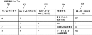
図2は、警告機能付きテーブルタップ111の記憶部119に保持される接続情報テーブルの一例を示す。接続情報テーブルは、図2に示すように、コンセント口番号201、コンセント利用状態202、電源スイッチON/OFF状態203、機器情報204、最大電力使用量205から構成されている。
コンセント利用状態202は、「0」のとき未使用(すなわち、コンセントに機器が接続されていない)、「1」のとき利用中(すなわち、コンセントに機器が接続されている)を示す。電源スイッチON/OFF状態203は、「0」のときOFF状態、「1」のときON状態を示す。
FIG. 2 shows an example of a connection information table held in the
The
機器情報204は、警告機能付きテーブルタップ111がコンセント口121に接続されている機器の機器情報を取得できる場合に接続情報テーブルに登録される。警告機能付きテーブルタップ111が機器情報を取得できない場合には、接続情報テーブルの機器情報204には「不明」が格納される。
例えば、コンセント口121に接続されている機器がPLCモデムを内蔵しており、それらの内部の記憶部に記憶している機器情報を警告機能付きテーブルタップ111に送信できる場合に、警告機能付きテーブルタップ111はその機器の機器情報をPLCモデム117で受信することにより、その機器の機器情報を取得することができる。
また、コンセント利用状態202が「0」(すなわち、未使用)のコンセント口の機器情報204には「NULL」が登録される。
最大電力使用量205には、コンセント口121に現在接続されている機器の過去における最大の使用電力量が登録される。
The
For example, when the device connected to the
Also, “NULL” is registered in the
In the
例えば、警告機能付きテーブルタップ111のコンセント口0番に電気ポットを接続したとする。この電気ポットは保温時200W、湯沸し時905Wの電力を消費し、過去に1度湯沸しを行っており、現在保温中の場合、記憶部119のテーブル情報は、コンセント口番号201として「0」、コンセント利用状態202として利用中を示す「1」、電源スイッチON/OFF状態203はON状態を示す「1」、機器情報204として「電気ポットの機器情報」、最大電力使用量205として「905」が登録されていることとなる。
For example, it is assumed that an electric pot is connected to the
警告機能付きテーブルタップ111のデータ処理部114は、接続情報テーブルについて、例えば、コンセント口121の一つに接続プラグが接続された時点および電源スイッチ122のON/OFF状態が変化した時点でそのコンセント口121に対応するコンセント口番号201のレコード情報を更新する。そして、コンセント口121の一つから接続プラグが抜かれた時点でそのコンセント口121に対応するコンセント口番号201のレコード情報をクリアする。
For the connection information table, the
また、使用電力量測定部120は、各コンセント口121について所定の間隔で(例えば、10分毎に)使用電力量を測定する。測定した結果、現在の使用電力量が最大電力使用量205に格納されている過去の最大電力使用量を超えている場合に、最大電力使用量205の情報を更新する。
記憶部119に接続情報テーブルを保持することにより、警告機能付きテーブルタップ111における最大電力使用量を知ることができ、より精度の高い警告を行うことができる。
The power consumption measuring unit 120 measures the power consumption for each
By holding the connection information table in the
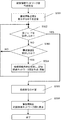
図3は、配線接続ネットワーク図作成処理の一例を示すフローチャートである。
利用者が、起動スイッチ108を押し、配線接続ネットワーク図の表示を指示した時、送受信部104は、配下の警告機能付きテーブルタップ111や補助プラグ123に対して構成情報を送信するように指示する送信命令をPLCモデム105を経由して配信する(S301)。なお、構成情報を送信するように指示する命令を送る際には、多重度情報として「1」を付加した状態で命令を送信する。
次に、送受信部104は配下の警告機能付きテーブルタップ111や補助プラグ123からの応答を待ち、受信した応答情報が終了コードであるか否かを判定する(S302)。送受信部104は、終了コードを受信していない場合(S302:NO)は、警告機能付きテーブルタップ111または補助プラグ123から構成情報を受信したか否か判定し(S303)、構成情報を受信した場合(S303:YES)は、警告機能付きテーブルタップ111からは各コンセント口121についてたこ足配線の多重度、コンセント口番号201、機器情報204、最大電力使用量205、使用中の電力量の情報が提供されているか否か判定する。また、補助プラグ123からはたこ足配線の多重度と使用中の電力量の情報が提供されているか否か判定する。警告機能付きテーブルタップ111または補助プラグ123からこれらの情報が提供されている場合、送受信部104はそれらの情報をデータ処理部103に渡し、データ処理部103は配線接続ネットワーク図を作成または更新する(S304)。
FIG. 3 is a flowchart illustrating an example of a wiring connection network diagram creation process.
When the user presses the
Next, the transmission /
一方、終了コードを受信した場合(S302:YES)は、データ処理部103が内部的に保持している一時領域であるメモリ内に保存している情報を利用し、多重接続が3重以上になっている箇所や最大電力使用量の合計値が警告機能付きテーブルタップ111の供給電力量を超える箇所、使用中の電力量が警告機能付きテーブルタップ111の供給電力量を超える箇所等の判定を行い、危険部位を特定する(S305)。
最後に特定した危険部位に対する警告情報を配線接続ネットワーク図上に表示する(S306)。
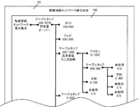
上述した処理の結果として、図4に示すような配線接続ネットワーク図が表示部102に表示される。
なお、終了コードを受信したか否かの判断(S302)において、一定時間が経過した場合はタイムアウトしたと判断し、終了コードを受信した場合(S302:YES)と同様の処理に進む。
On the other hand, when the end code is received (S302: YES), the information stored in the memory, which is a temporary area held internally by the
The warning information for the finally identified dangerous part is displayed on the wiring connection network diagram (S306).
As a result of the above-described processing, a wiring connection network diagram as shown in FIG.
In the determination of whether or not the end code has been received (S302), it is determined that a time-out has occurred if a predetermined time has elapsed, and the processing proceeds to the same processing as when the end code has been received (S302: YES).
図5は、警告機能付きテーブルタップ111の構成情報提供処理の一例を示すフローチャートである。
利用者が配線接続ネットワーク表示端末101の起動スイッチ108を押し、配線接続ネットワーク図の表示を指示した場合、警告機能付きテーブルタップ111の送受信部114は構成情報の送信命令を受信する(S401)。
FIG. 5 is a flowchart illustrating an example of the configuration information providing process of the
When the user presses the
送受信部115は、構成情報の送信命令を受信すると、警告機能付きテーブルタップ111に存在する全てのコンセント口121における構成情報を上位機器に送信したか否かの確認を行い(S402)、未送信のコンセント口121が残っている場合(S402:NO)は、対象となるコンセント口121の情報を記憶部119に保持されている接続情報テーブルから取得する(ステップ403)。
次に、送受信部115は、接続情報テーブルから取得した機器情報204がテーブルタップ又は不明な機器の情報であるか否かの判断を行い(S404)、テーブルタップ又は不明な機器となっていた場合(S404:YES)は、ステップ401で受信した構成情報の送信命令に付加されている多重度情報をインクリメントして構成情報の送信命令を配下の機器へ送信する(S407)。
その後、送受信部115は、配下の機器からの回答を受信した場合、終了コードを受信したか否かの判断を行う(S408)。終了コードを受信していない場合(S408:NO)は、配下の機器から送信された構成情報を中継し、上位の機器へ送信する(S409)。
When the transmission /
Next, the transmission /
Thereafter, when receiving a response from a subordinate device, the transmission /
一方、終了コードを受信した場合(S408:YES)は、送受信部115は、対象となっているコンセント口121の構成情報の送信処理へ戻り、使用電力量測定部120へ使用電力量の測定を指示して使用電力量測定部120に測定を行わせる(S405)。
次に、送受信部115は、たこ足配線の多重度、記憶部119に保持されている接続情報テーブルに登録されていたコンセント口番号201、機器情報204、最大電力使用量205、測定した使用電力量の情報を対象となっているコンセント口121の構成情報としてまとめて上位機器へ送信し(S406)、ステップS402の全てのコンセント口の構成情報を送信したか否かの判断に戻る。
なお、機器情報がテーブルタップ又は不明であるかの判断において(S404)、テーブルタップ及び不明機器ではないと判断された場合(S404:NO)、送受信部115は、使用電力量測定部120へ使用電力量の測定を指示して使用電力量測定部120に測定を行わせ(S405)、たこ足配線の多重度、記憶部119に保持されている接続情報テーブルに登録されていたコンセント口番号201、機器情報204、最大電力使用量205、ステップS405で測定した使用電力量の情報を構成情報としてまとめて上位機器へ送信し(S406)、ステップS402の全てのコンセント口の構成情報を送信したか否かの判断に戻る。
最後に、全てのコンセント口の構成情報を送信したか否かの判断(S402)にて全てのコンセント口の構成情報を送信したとの判断がされた場合(S402:YES)、終了コードを送信する(S410)。
なお、終了コードを受信したか否かの判定(S408)において、一定時間が経過した場合には送受信部115はタイムアウトしたと判断し、終了コードを受信した場合(S408:YES)と同様の処理に進む。
On the other hand, when the end code is received (S408: YES), the transmission /
Next, the transmission /
In the determination of whether the device information is a table tap or unknown (S404), if it is determined that the device information is not a table tap or an unknown device (S404: NO), the transmission /
Finally, when it is determined that the configuration information of all outlets has been transmitted (S402: YES), the end code is transmitted. (S410).
In the determination of whether or not the end code has been received (S408), if the predetermined time has elapsed, the transmission /
図6は、補助プラグ123の構成情報提供処理の一例を示すフローチャートである。
送受信部126は、上位の機器(配線接続ネットワーク表示端末101または警告機能付きテーブルタップ111)から構成情報を送信することを指示する命令を受信する(S501)と、コンセント口124の使用電力量を使用電力量測定部127で測定する(S502)。そして、送受信部126は、上位の機器に対して、補助プラグ123におけるたこ足配線の多重度(命令を受信した際に指定されていた多重度情報)および測定した使用電力量を構成情報としてまとめて上位の機器に送信し(S503)、終了コードを送信する(S504)。
FIG. 6 is a flowchart illustrating an example of the configuration information providing process of the
When the transmission /
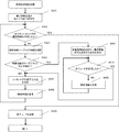
図7は、警告機能付きテーブルタップ111の警告表示処理の一例を示すフローチャートである。
配線接続ネットワーク表示端末101を利用していない場合でも、警告機能付きテーブルタップ111で簡易の警告を表示することができる。この場合、図7に示すように、利用者が起動スイッチ113を押して警告の表示を指示した時、送受信部115は、まず最初に、警告機能付きテーブルタップ111に存在する全てのコンセント口121に対する記憶部119に保持されている接続情報テーブルの内容確認が終了しているか否か判定を行う(S601)。内容確認が終わっていないコンセント口がある場合(S601:NO)は、記憶部119に保持されている接続情報テーブルの内容を確認する(S602)。
そして、機器情報204に保持されている情報がテーブルタップ又は不明であるか否かの判定を行い(S603)、テーブルタップ又は不明であると判断された場合(S603:YES)、多重度情報として例えば「2」を付加した構成情報の送信命令を配下の機器へ送信する(S604)。
FIG. 7 is a flowchart showing an example of warning display processing of the
Even when the wired connection
Then, it is determined whether or not the information held in the
次に、送受信部115は配下の機器からの回答を受信するまで待機状態となり、配下の機器から何らかの回答を受信した場合に終了コードを受信したか否かの判定を行う(S605)。判定の結果、終了コードでないと判断された場合(S605:NO)は、受信した情報に含まれるたこ足配線の多重度と一時情報としてデータ処理部114の内部メモリ内に保持している対象となるコンセント口121のたこ足配線の多重度を比較し、受信情報に含まれるたこ足配線の多重度が大きい場合は一時情報としてデータ処理部114の内部メモリ内に保持しているたこ足配線の多重度を受信情報に含まれるたこ足配線の多重度で上書きし(S606)、回答の受信待機状態に戻る。
Next, the transmission /
一方、何らかの回答を受信した場合に終了コードを受信したか否かの判定(S605)において、終了コードを受信したと判断された場合(S605:YES)や、機器情報204に保持されている情報がテーブルタップ及び不明であるか否かの判定(S603)において、テーブルタップ及び不明ではないと判断された場合(S603:NO)、全てのコンセント口121に対する記憶部119に保持されている接続情報テーブルの内容確認が終了しているか否かの判定(S601)に戻る。
なお、終了コードを受信したか否かの判定(S605)において、一定時間が経過した場合はタイムアウトしたと判断し、終了コードを受信した場合(S605:YES)と同様の処理に進む。
On the other hand, when it is determined that an end code has been received (S605: YES) in the determination as to whether or not an end code has been received when some answer is received (S605: YES), information held in the
In the determination of whether or not the end code has been received (S605), it is determined that a time-out has occurred when a predetermined time has elapsed, and the process proceeds to the same processing as when the end code has been received (S605: YES).
また、全てのコンセント口121に対する記憶部119に保持されている接続情報テーブルの内容確認が終了しているか否かの判定(S601)において、全てのコンセント口121の内容確認が完了したと判断された場合(S601:YES)、使用電力量測定部120を利用して、各コンセント口121の使用電力量を測定し(S607)、使用中の電力量がテーブルタップの供給電力量を超えるか、一時情報としてデータ処理部114の内部メモリ内に保持しているたこ足配線の多重度において多重接続が3重以上になっている箇所がないかの警告判定を行い(S608)、使用中の電力量、各コンセント口のたこ足配線の多重度等の警告判定により警告が必要と判断された情報を表示部116に表示する(S609)。
In addition, in the determination of whether or not the confirmation of the contents of the connection information table held in the
本発明によれば、テーブルタップについて使用電力量の警告やたこ足配線の警告をユーザに行うことができる。また、テーブルタップの配線接続ネットワーク表示を行う専用表示端末による視覚的な配線状況の表示により、許容量以上の電力利用や、多重度の高いたこ足配線による漏電・発火の危険を未然に防ぐことができる。 ADVANTAGE OF THE INVENTION According to this invention, the warning of the amount of electric power used and the warning of a octopus wiring can be performed to a user about a table tap. In addition, by using a dedicated display terminal that displays the wiring connection network of the table taps, it is possible to prevent the risk of electric leakage and fire due to the use of power exceeding the allowable amount and the multiplicity of the octopus foot wiring by visual display of the wiring status. Can do.
101…配線接続ネットワーク表示端末、102…配線接続ネットワーク端末の表示部、103…配線接続ネットワーク端末のデータ処理部、104…配線接続ネットワーク端末の送受信部、105…配線接続ネットワーク端末のPLCモデム、106…配線接続ネットワーク端末の表示処理部、107…配線接続ネットワーク端末の操作部、108…配線接続ネットワーク端末の起動スイッチ、109…配線接続ネットワーク端末のコンセント口、110…配線接続ネットワーク端末の接続プラグ、111…警告機能付きテーブルタップ、112…警告機能付きテーブルタップの接続プラグ、113…警告機能付きテーブルタップの起動スイッチ、114…警告機能付きテーブルタップのデータ処理部、115…警告機能付きテーブルタップの送受信部、116…警告機能付きテーブルタップの表示部、117…警告機能付きテーブルタップのPLCモデム、118…警告機能付きテーブルタップの表示処理部、119…警告機能付きテーブルタップの記憶部、120…警告機能付きテーブルタップの使用電力量測定部、121…警告機能付きテーブルタップのコンセント口、122…警告機能付きテーブルタップの電源スイッチ、123…補助プラグ、124…補助プラグのコンセント口、125…補助プラグのPLCモデム、126…補助プラグの送受信部、127…補助プラグの使用電力量測定部、128…既存のテーブルタップ、129…既存のテーブルタップのコンセント口、130…既存のテーブルタップの接続プラグ、131…機器A、132…機器Aの接続プラグ、133…機器B、134…機器Bの接続プラグ、201…コンセント口番号、202…コンセント利用状態、203…電源スイッチON/OFF状態、204…機器情報、205…最大電力使用量
DESCRIPTION OF
Claims (4)
前記警告機能付きテーブルタップが、
複数のコンセント口と、
電気配線を利用してデータ通信を行う第1のPLCモデムと、
前記コンセント口毎に、使用電力量を測定する第1の使用電力量測定手段と、
前記コンセント口毎に、前記第1の使用電力量測定手段によって過去に測定された最大の使用電力量である最大電力使用量を記憶する最大電力使用量記憶手段と、
前記コンセント口毎に、たこ足配線の多重度を求める第1の多重度取得手段と、
前記第1の使用電力量測定手段によって測定された現在の使用電力量と、前記最大電力使用量記憶手段に記憶されている最大電力使用量と、前記第1の多重度取得手段によって求められたたこ足配線の多重度とを含む第1の構成情報を前記第1のPLCモデムにより送信する第1の構成情報送信手段と、
を備え、
前記配線接続ネットワーク表示端末が、
電気配線を利用してデータ通信を行う第2のPLCモデムと、
前記警告機能付きテーブルタップから送信された前記第1の構成情報を前記第2のPLCモデムにより受信する第1の構成情報受信手段と、
前記第1の構成情報受信手段によって受信された第1の構成情報に含まれる現在の使用電力量と最大電力使用量とたこ足配線の多重度とに基づいて所定の警告情報を作成する警告情報作成手段と、
前記警告情報作成手段によって作成された警告情報を表示する表示手段と、
を備える、
ことを特徴とするテーブルタップ警告システム。 A table tap warning system having a table tap with a warning function and a wired connection network display terminal,
The table tap with warning function is
Multiple outlets,
A first PLC modem for performing data communication using electrical wiring;
First power consumption measuring means for measuring the power consumption for each outlet port;
Maximum power usage storage means for storing maximum power usage, which is the maximum power consumption measured in the past by the first power usage measurement means, for each outlet port;
First multiplicity acquisition means for determining the multiplicity of the octopus wiring for each outlet port;
The current power consumption measured by the first power consumption measuring unit, the maximum power usage stored in the maximum power usage storage unit, and the first multiplicity acquisition unit. First configuration information transmitting means for transmitting first configuration information including the multiplicity of the tactile wiring by the first PLC modem;
With
The wired connection network display terminal is
A second PLC modem for data communication using electrical wiring;
First configuration information receiving means for receiving the first configuration information transmitted from the table tap with warning function by the second PLC modem;
Warning information for creating predetermined warning information based on the current power consumption, the maximum power usage, and the multiplicity of the octopus wiring included in the first configuration information received by the first configuration information receiving means Creating means;
Display means for displaying the warning information created by the warning information creating means;
Comprising
Table tap warning system characterized by that.
前記補助プラグが、
補助コンセント口と、
電気配線を利用してデータ通信を行う第3のPLCモデムと、
前記補助コンセント口における使用電力量を測定する第2の使用電力量測定手段と、
当該補助プラグにおけるたこ足配線の多重度を求める第2の多重度取得手段と、
前記第2の使用電力量測定手段によって測定された現在の使用電力量と、前記第2の多重度取得手段によって求められたたこ足配線の多重度とを含む第2の構成情報を前記第3のPLCモデムにより送信する第2の構成情報送信手段と、
を有し、
前記警告機能付きテーブルタップは、
前記補助プラグの第2の構成情報送信手段によって送信される第2の構成情報を前記第1のPLCモデムにより受信する第2の構成情報受信手段を備え、
前記第1の構成情報送信手段が、前記第1の構成情報とともに前記第2の構成情報受信手段によって受信された第2の構成情報を送信し、
前記配線接続ネットワーク表示端末は、
前記第1の構成情報受信手段が、前記第1の構成情報とともに前記第2の構成情報を受信し、
前記警告情報作成手段が、前記第1の構成情報に含まれる現在の使用電力量と最大電力使用量とたこ足配線の多重度および前記第2の構成情報に含まれる現在の使用電力量とたこ足配線の多重度に基づいて所定の警告情報を作成する、
ことを特徴とする請求項1に記載のテーブルタップ警告システム。 An auxiliary plug connected to an outlet of a table tap that does not have the first power consumption measuring unit and the first multiplicity acquisition unit;
The auxiliary plug is
An auxiliary outlet,
A third PLC modem for data communication using electrical wiring;
Second power consumption measuring means for measuring the power consumption at the auxiliary outlet,
A second multiplicity acquisition means for determining the multiplicity of the octopus wiring in the auxiliary plug;
The second configuration information including the current power consumption measured by the second power consumption measuring unit and the multiplicity of the octopus wiring obtained by the second multiplicity acquisition unit is the third configuration information. Second configuration information transmitting means for transmitting by the PLC modem of
Have
The table tap with warning function is
Second configuration information receiving means for receiving, by the first PLC modem, second configuration information transmitted by the second configuration information transmitting means of the auxiliary plug;
The first configuration information transmitting means transmits the second configuration information received by the second configuration information receiving means together with the first configuration information;
The wire connection network display terminal is
The first configuration information receiving means receives the second configuration information together with the first configuration information;
The warning information creating means includes a current power consumption amount and a maximum power usage amount included in the first configuration information, a multiplicity of tachometer wiring, and a current power consumption amount and a tako included in the second configuration information. Create predetermined warning information based on multiplicity of foot wiring,
The table tap warning system according to claim 1.
複数のコンセント口と、
電気配線を利用してデータ通信を行う第1のPLCモデムと、
前記コンセント口毎に、使用電力量を測定する第1の使用電力量測定手段と、
前記コンセント口毎に、前記第1の使用電力量測定手段によって過去に測定された最大の使用電力量である最大電力使用量を記憶する最大電力使用量記憶手段と、
前記コンセント口毎に、たこ足配線の多重度を求める第1の多重度取得手段と、
前記第1の使用電力量測定手段によって測定された現在の使用電力量と、前記最大電力使用量記憶手段に記憶されている最大電力使用量と、前記第1の多重度取得手段によって求められたたこ足配線の多重度とを含む第1の構成情報を前記第1のPLCモデムにより送信する第1の構成情報送信手段と、
を備えることを特徴とする警告機能付きテーブルタップ。 A table tap with a warning function used in a table tap warning system having a table tap with a warning function and a wired connection network display terminal,
Multiple outlets,
A first PLC modem for performing data communication using electrical wiring;
First power consumption measuring means for measuring the power consumption for each outlet port;
Maximum power usage storage means for storing maximum power usage, which is the maximum power consumption measured in the past by the first power usage measurement means, for each outlet port;
First multiplicity acquisition means for determining the multiplicity of the octopus wiring for each outlet port;
The current power consumption measured by the first power consumption measuring unit, the maximum power usage stored in the maximum power usage storage unit, and the first multiplicity acquisition unit. First configuration information transmitting means for transmitting first configuration information including the multiplicity of the tactile wiring by the first PLC modem;
Table tap with warning function, characterized by comprising.
補助コンセント口と、
電気配線を利用してデータ通信を行う第3のPLCモデムと、
前記補助コンセント口における使用電力量を測定する第2の使用電力量測定手段と、
当該補助プラグにおけるたこ足配線の多重度を求める第2の多重度取得手段と、
前記第2の使用電力量測定手段によって測定された現在の使用電力量と、前記第2の多重度取得手段によって求められたたこ足配線の多重度とを含む第2の構成情報を前記第3のPLCモデムにより送信する第2の構成情報送信手段と、
を備えることを特徴とする補助プラグ。 An auxiliary plug used in a table tap warning system having a table tap with a warning function, a wiring connection network display terminal, and an auxiliary plug, and connected to the outlet of the table tap,
An auxiliary outlet,
A third PLC modem for data communication using electrical wiring;
Second power consumption measuring means for measuring the power consumption at the auxiliary outlet,
A second multiplicity acquisition means for determining the multiplicity of the octopus wiring in the auxiliary plug;
The second configuration information including the current power consumption measured by the second power consumption measuring unit and the multiplicity of the octopus wiring obtained by the second multiplicity acquisition unit is the third configuration information. Second configuration information transmitting means for transmitting by the PLC modem of
Auxiliary plug characterized by comprising.
Priority Applications (1)
| Application Number | Priority Date | Filing Date | Title |
|---|---|---|---|
| JP2011062126A JP2012199057A (en) | 2011-03-22 | 2011-03-22 | Table tap warning system, table tap with warning function, and auxiliary plug |
Applications Claiming Priority (1)
| Application Number | Priority Date | Filing Date | Title |
|---|---|---|---|
| JP2011062126A JP2012199057A (en) | 2011-03-22 | 2011-03-22 | Table tap warning system, table tap with warning function, and auxiliary plug |
Publications (1)
| Publication Number | Publication Date |
|---|---|
| JP2012199057A true JP2012199057A (en) | 2012-10-18 |
Family
ID=47181096
Family Applications (1)
| Application Number | Title | Priority Date | Filing Date |
|---|---|---|---|
| JP2011062126A Withdrawn JP2012199057A (en) | 2011-03-22 | 2011-03-22 | Table tap warning system, table tap with warning function, and auxiliary plug |
Country Status (1)
| Country | Link |
|---|---|
| JP (1) | JP2012199057A (en) |
-
2011
- 2011-03-22 JP JP2011062126A patent/JP2012199057A/en not_active Withdrawn
Similar Documents
| Publication | Publication Date | Title |
|---|---|---|
| EP2625985B1 (en) | Power distribution control of a furniture arrangment | |
| JP4446854B2 (en) | Power strip | |
| JP2014032677A (en) | Handheld devices, systems, and methods for measuring parameters | |
| JP2015005856A5 (en) | ||
| CN103794955B (en) | Intelligent power supply system and Intelligent socket thereof and intelligent power supply method | |
| KR101182780B1 (en) | Smart meter apparatus for efficient power management and power managing method using the same apparatus | |
| KR20160003517A (en) | Smart plug and socket, and smart power consumption control system for using the same | |
| JP5563974B2 (en) | Equipment management system | |
| KR100920992B1 (en) | Remote control power strip / outlet device | |
| KR20140062809A (en) | Intelligent plug system and communication system using the same | |
| KR20160100565A (en) | Smart Power Plug System Using Wireless Communication Network | |
| CN101594384B (en) | Method for controlling remote device by using real-time message and control device | |
| KR101479659B1 (en) | Method for individual and group controlling for multitap based on wireless communication and individual multitap and multitap group controlled based on wireless communication | |
| TW201429104A (en) | Power connection device | |
| JP2012199057A (en) | Table tap warning system, table tap with warning function, and auxiliary plug | |
| CN203103676U (en) | Intelligent socket and intelligent socket control system | |
| JP2011072099A (en) | Power supply system | |
| KR102758696B1 (en) | A remote controllable outlet system with a detachable/removable control plug | |
| JP2020058198A (en) | Management device | |
| KR101370996B1 (en) | System for controlling standby power of three-phase type load equipment | |
| CN109494875B (en) | Remote control device for substation equipment | |
| CN204835087U (en) | Take intelligent energy -conserving socket system of remote controller | |
| CN204462825U (en) | A kind of energy consumption monitoring device and comprise the household electrical appliance energy consumption monitoring system of this device | |
| KR101767259B1 (en) | Automatic power-saving control apparatus for using remote control signal | |
| JP2015216751A (en) | Portable terminal, management device, distribution panel, and distribution panel monitoring system |
Legal Events
| Date | Code | Title | Description |
|---|---|---|---|
| A300 | Withdrawal of application because of no request for examination |
Free format text: JAPANESE INTERMEDIATE CODE: A300 Effective date: 20140603 |