JP2012198700A - Light detection device and paper sheet processor including light detection device - Google Patents

Light detection device and paper sheet processor including light detection device Download PDF

Info

Publication number
JP2012198700A
JP2012198700A JP2011061696A JP2011061696A JP2012198700A JP 2012198700 A JP2012198700 A JP 2012198700A JP 2011061696 A JP2011061696 A JP 2011061696A JP 2011061696 A JP2011061696 A JP 2011061696A JP 2012198700 A JP2012198700 A JP 2012198700A
Authority
JP
Japan
Prior art keywords
unit
light
image
paper sheet
light source
Prior art date
Legal status (The legal status is an assumption and is not a legal conclusion. Google has not performed a legal analysis and makes no representation as to the accuracy of the status listed.)
Pending
Application number
JP2011061696A
Other languages
Japanese (ja)
Inventor
Toshiyuki Tanaka
利之 田中
Current Assignee (The listed assignees may be inaccurate. Google has not performed a legal analysis and makes no representation or warranty as to the accuracy of the list.)
Toshiba Corp
Original Assignee
Toshiba Corp
Priority date (The priority date is an assumption and is not a legal conclusion. Google has not performed a legal analysis and makes no representation as to the accuracy of the date listed.)
Filing date
Publication date
Application filed by Toshiba Corp filed Critical Toshiba Corp
Priority to JP2011061696A priority Critical patent/JP2012198700A/en
Publication of JP2012198700A publication Critical patent/JP2012198700A/en
Pending legal-status Critical Current

Links

Images

Landscapes

  • Sorting Of Articles (AREA)
  • Character Input (AREA)
  • Image Input (AREA)
  • Character Discrimination (AREA)
  • Facsimile Scanning Arrangements (AREA)

Abstract

PROBLEM TO BE SOLVED: To provide a light detection device capable of accurately detecting a position by a simple configuration, and a paper sheet processor including the light detection device.SOLUTION: The light detection device related to one embodiment comprises: an illumination part including a first illumination part and a second illumination part for irradiating conveyed paper sheets with light; a light receiving part for receiving the light from a scanning range on a conveyance surface where the paper sheets are conveyed; an image acquisition part for acquiring images on the basis of the light received by the light receiving part; and a control part for controlling the image acquisition part so as to acquire a first image by the image acquisition part when the first illumination part of the illumination part is lighted and to acquire a second image by the image acquisition part when the second illumination part of the illumination part is lighted. The first illumination part includes a first light source provided such that an optical axis forms a prescribed angle to the paper sheets and a second light source provided on a position facing the first light source relative to the optical axis of the light receiving part, and the second illumination part has one of the first light source and the second light source.

Description

本発明の実施形態は、光検出装置、及び光検出装置を備える紙葉類処理装置に関する。   Embodiments described herein relate generally to a light detection device and a paper sheet processing apparatus including the light detection device.

従来、例えば郵便物などの紙葉類を処理する郵便区分機などの紙葉類処理装置が実用化されている。このような紙葉類処理装置は、投入部に投入された紙葉類を1枚ずつ取り込み、紙葉類の認識装置に搬送する。認識装置は、紙葉類から画像を取得し、取得した画像に基づいて、例えば宛先情報、及び切手の位置などを認識する。紙葉類処理装置は、認識結果に基づいて、切手に押印し、紙葉類を所定の区分ポケットに区分する。   2. Description of the Related Art Conventionally, a paper sheet processing apparatus such as a mail sorting machine that processes paper sheets such as mail has been put into practical use. Such a paper sheet processing apparatus takes in the paper sheets input into the input unit one by one and conveys them to the paper sheet recognition apparatus. The recognition device acquires an image from a paper sheet, and recognizes, for example, destination information and a stamp position based on the acquired image. Based on the recognition result, the paper sheet processing apparatus stamps the stamp and sorts the paper sheet into predetermined sorting pockets.

紙葉類処理装置で処理する紙葉類には、窓枠が存在するものがある。このような紙葉類では、窓枠の内部に宛先情報が記載されている場合が多い。切手及び窓枠の内部は、紙葉類の表面とは高さが異なる場合が多い。そこで、認識装置は、紙葉類に対して斜めから光を照射する。これにより、紙葉類の凹凸箇所に陰影ができる。認識装置は、この反射光に基づいて画像を取得し、取得した画像に基づいて、切手及び窓枠の位置を認識する。認識装置は、窓枠の中の画像に基づいて文字認識処理を行い、宛先情報を認識する。さらに、紙葉類処理装置は、切手が貼付されている位置に押印する。   Some paper sheets processed by the paper sheet processing apparatus include a window frame. In such paper sheets, destination information is often described inside the window frame. The insides of stamps and window frames are often different in height from the surface of paper sheets. Therefore, the recognition device irradiates light on the paper sheet obliquely. Thereby, a shadow is made on the uneven portion of the paper sheet. The recognition device acquires an image based on the reflected light, and recognizes the positions of the stamp and the window frame based on the acquired image. The recognition device recognizes destination information by performing character recognition processing based on the image in the window frame. Further, the paper sheet handling apparatus stamps the position where the stamp is pasted.

特開平8−30785号公報JP-A-8-30785

しかし、紙葉類に対して斜めから照射された光の反射光から画像を取得した場合、紙葉類の折れ目などの凹凸により陰影ができる可能性がある。この為、文字認識処理が正確に行われない場合がある。そこで、斜めから照射された光から位置検出用画像を取得するセンサと、影が出来ないように照射された光から文字認識用画像を取得するセンサとの二つのセンサを備える認識装置がある。   However, when an image is acquired from reflected light of light irradiated obliquely onto a paper sheet, there is a possibility that a shadow may be formed due to unevenness such as a fold of the paper sheet. For this reason, the character recognition process may not be performed accurately. Therefore, there is a recognition device that includes two sensors, a sensor that acquires a position detection image from light irradiated obliquely and a sensor that acquires a character recognition image from light irradiated so as not to make a shadow.

しかし、このような認識装置は、位置検出用画像から切手及び窓枠の位置を検出し、検出された位置と、文字認識用画像とに基づいて文字認識を行う。この為、二つのセンサにより取得された画像中における切手及び窓枠の位置がずれている場合、正確に文字認識処理を行う事ができないという課題がある。また、受光系を二つ備える為、コストが高い、装置が大きくなるなどの課題がある。   However, such a recognition device detects the positions of the stamp and the window frame from the position detection image, and performs character recognition based on the detected position and the character recognition image. For this reason, when the positions of the stamp and the window frame in the images acquired by the two sensors are displaced, there is a problem that the character recognition process cannot be performed accurately. In addition, since two light receiving systems are provided, there are problems such as high cost and large apparatus.

そこで、簡易な構成でより正確に位置検出を行うことができる光検出装置、及び光検出装置を備える紙葉類処理装置を提供することを目的とする。   Accordingly, it is an object of the present invention to provide a light detection device capable of performing position detection more accurately with a simple configuration, and a paper sheet processing device including the light detection device.

一実施形態に係る光検出装置は、搬送される紙葉類に対して光を照射する第1の照明部と、第2の照明部と、を有する照明部と、前記紙葉類が搬送される搬送面上の走査範囲から光を受光する受光部と、前記受光部により受光された光に基づいて画像を取得する画像取得部と、前記照明部の前記第1の照明部が点灯している場合に前記画像取得部により第1の画像を取得し、前記照明部の前記第2の照明部が点灯している場合に前記画像取得部により第2の画像を取得するように前記画像取得部を制御する制御部と、を具備し、前記第1の照明部は、光軸が前記紙葉類に対して所定の角度を成すように設けられた第1の光源と、前記受光部の光軸に対して前記第1の光源と対向する位置に設けられた第2の光源とを有し、前記第2の照明部は、前記第1の光源と前記第2の光源とのうちのいずれか1つを有する。   An optical detection device according to an embodiment includes an illumination unit including a first illumination unit that irradiates light to a conveyed paper sheet and a second illumination unit, and the paper sheet is conveyed. A light receiving unit that receives light from a scanning range on the conveyance surface, an image acquisition unit that acquires an image based on the light received by the light receiving unit, and the first illumination unit of the illumination unit The image acquisition unit acquires the first image when the image acquisition unit is on, and the image acquisition unit acquires the second image by the image acquisition unit when the second illumination unit of the illumination unit is turned on. A control unit that controls the first illumination unit, wherein the first illumination unit includes a first light source provided so that an optical axis forms a predetermined angle with respect to the paper sheet, and the light receiving unit. A second light source provided at a position facing the first light source with respect to the optical axis, and the second illumination unit includes: Having any one of the first light source and the second light source.

図1は、一実施形態に係る紙葉類処理装置について説明するための図である。FIG. 1 is a diagram for explaining a paper sheet processing apparatus according to an embodiment. 図2は、一実施形態に係る紙葉類処理装置により処理される紙葉類の例について説明するための図である。FIG. 2 is a diagram for describing an example of paper sheets processed by the paper sheet processing apparatus according to the embodiment. 図3は、一実施形態に係る光検出装置について説明するための図である。FIG. 3 is a diagram for explaining a photodetection device according to an embodiment. 図4は、一実施形態に係る光検出装置について説明するための図である。FIG. 4 is a diagram for explaining a photodetection device according to an embodiment. 図5は、一実施形態に係る光検出装置について説明するための図である。FIG. 5 is a diagram for explaining a photodetection device according to an embodiment. 図6は、一実施形態に係る光検出装置について説明するための図である。FIG. 6 is a diagram for explaining a photodetection device according to an embodiment. 図7は、一実施形態に係る光検出装置について説明するための図である。FIG. 7 is a diagram for explaining a photodetection device according to an embodiment. 図8は、一実施形態に係る光検出装置について説明するための図である。FIG. 8 is a diagram for explaining a photodetection device according to an embodiment. 図9は、一実施形態に係る光検出装置について説明するための図である。FIG. 9 is a diagram for explaining a photodetection device according to an embodiment. 図10は、一実施形態に係る光検出装置について説明するための図である。FIG. 10 is a diagram for explaining a photodetection device according to an embodiment. 図11は、一実施形態に係る光検出装置について説明するための図である。FIG. 11 is a diagram for explaining a photodetection device according to an embodiment. 図12は、一実施形態に係る光検出装置について説明するための図である。FIG. 12 is a diagram for explaining a photodetection device according to an embodiment. 図13は、一実施形態に係る光検出装置について説明するための図である。FIG. 13 is a diagram for describing a photodetection device according to an embodiment.

(第1の実施形態)
以下、図面を参照しながら、一実施形態に係る紙葉類処理装置、及び光検出装置について詳細に説明する。
(First embodiment)
Hereinafter, a paper sheet processing apparatus and a light detection apparatus according to an embodiment will be described in detail with reference to the drawings.

図1は、一実施形態に係る紙葉類処理装置100の構成例を示す。
紙葉類処理装置100は、紙葉類から画像を読み取って、読み取った画像から宛先情報及び切手の貼付位置などを認識し、紙葉類に押印し、紙葉類を区分する。紙葉類処理装置100は、供給部20、分離ローラ25、搬送路30、光検出装置40、押印部46、印刷部47、主制御部50、区分処理部60、操作部70、表示部80、及び入出力部90を備える。
FIG. 1 shows a configuration example of a paper sheet processing apparatus 100 according to an embodiment.
The paper sheet processing apparatus 100 reads an image from the paper sheet, recognizes destination information and a stamping position from the read image, and stamps the paper sheet to classify the paper sheet. The paper sheet processing apparatus 100 includes a supply unit 20, a separation roller 25, a conveyance path 30, a light detection device 40, a stamping unit 46, a printing unit 47, a main control unit 50, a sorting processing unit 60, an operation unit 70, and a display unit 80. And an input / output unit 90.

主制御部50は、紙葉類処理装置100の各部の動作を統合的に制御する。主制御部50は、CPU、バッファメモリ、プログラムメモリ、及び不揮発性メモリなどを備える。CPUは、種々の演算処理を行う。バッファメモリは、CPUにより行われる演算の結果を一時的に記憶する。プログラムメモリ及び不揮発性メモリは、CPUが実行する種々のプログラム及び制御データなどを記憶する。主制御部50は、CPUによりプログラムメモリに記憶されているプログラムを実行することにより、種々の処理を行うことができる。   The main control unit 50 controls the operation of each unit of the paper sheet processing apparatus 100 in an integrated manner. The main control unit 50 includes a CPU, a buffer memory, a program memory, a nonvolatile memory, and the like. The CPU performs various arithmetic processes. The buffer memory temporarily stores the results of calculations performed by the CPU. The program memory and the nonvolatile memory store various programs executed by the CPU, control data, and the like. The main control unit 50 can perform various processes by executing a program stored in the program memory by the CPU.

供給部20は、紙葉類処理装置100に取り込む紙葉類1をストックする。供給部20は、重ねられた状態の紙葉類1をまとめて受け入れる。   The supply unit 20 stocks the paper sheets 1 to be taken into the paper sheet processing apparatus 100. The supply unit 20 collectively receives the stacked paper sheets 1.

分離ローラ25は、例えば供給部20の下端に設置される。分離ローラ25は、供給部20に紙葉類1が投入された場合、投入された紙葉類1の集積方向の下端に接する。分離ローラ25は、回転することにより、供給部20にセットされた紙葉類1を集積方向の下端から1枚ずつ紙葉類処理装置100の内部に取り込む。   The separation roller 25 is installed at the lower end of the supply unit 20, for example. When the paper sheet 1 is input to the supply unit 20, the separation roller 25 contacts the lower end of the input paper sheet 1 in the stacking direction. The separation roller 25 rotates to take the sheets 1 set in the supply unit 20 one by one from the lower end in the stacking direction into the sheet processing apparatus 100.

分離ローラ25は、たとえば、1回転するごとに1枚の紙葉類1を取り込む。これにより、分離ローラ25は、紙葉類1を一定のピッチで取り込むことができる。分離ローラ25により取り込まれた紙葉類1は、搬送路30に導入される。   For example, the separation roller 25 takes in one sheet 1 every rotation. Thereby, the separation roller 25 can take in the paper sheets 1 at a constant pitch. The paper sheet 1 taken in by the separation roller 25 is introduced into the conveyance path 30.

搬送路30は、紙葉類1を紙葉類処理装置100内の各部に搬送する搬送部である。搬送路30は、図示しない搬送ベルト及び図示しない駆動プーリなどを備える。搬送路30は、図示しない駆動モータにより駆動プーリを駆動する。搬送ベルトは、駆動プーリにより動作する。   The conveyance path 30 is a conveyance unit that conveys the paper sheet 1 to each part in the paper sheet processing apparatus 100. The conveyance path 30 includes a conveyance belt (not shown) and a drive pulley (not shown). The conveyance path 30 drives a drive pulley by a drive motor (not shown). The conveyor belt is operated by a driving pulley.

搬送路30は、分離ローラ25により取り込む紙葉類1を搬送ベルトにより一定速度で矢印a(搬送方向a)の方向に搬送する。なお、搬送路30において分離ローラ25に近い側を上流側、逆側を下流側として説明する。   The conveyance path 30 conveys the paper sheet 1 taken in by the separation roller 25 in the direction of arrow a (conveyance direction a) at a constant speed by the conveyance belt. In addition, the side close to the separation roller 25 in the conveyance path 30 will be described as an upstream side, and the opposite side will be described as a downstream side.

光検出装置40は、搬送路30により搬送される紙葉類1から画像を取得する。光検出装置40は、例えば、照明と光学センサとを備える。照明は、搬送路30により搬送される紙葉類1に対して光を照射する。光学センサは、紙葉類1で反射する反射光に基づいて画像を取得する。さらに、光検出装置40は、取得した画像に基づいて、切手の貼付位置(切手位置情報)、及び宛先情報を取得し、主制御部50に伝送する。なお、光検出装置40については後述する。   The light detection device 40 acquires an image from the paper sheet 1 conveyed by the conveyance path 30. The light detection device 40 includes, for example, illumination and an optical sensor. The illumination irradiates the paper sheet 1 conveyed by the conveyance path 30 with light. The optical sensor acquires an image based on the reflected light reflected by the paper sheet 1. Further, the light detection device 40 acquires a stamp pasting position (stamp position information) and destination information based on the acquired image, and transmits them to the main control unit 50. The light detection device 40 will be described later.

主制御部50は、光検出装置40から伝送された宛先情報に基づいて、紙葉類1の搬送先を判定する。さらに、主制御部50は、宛先情報に基づいて2次元コード、またはバーコードなどのイメージを生成し、生成したイメージを印刷部47に供給する。またさらに、主制御部50は、光検出装置40から伝送された切手の貼付位置(切手位置情報)に基づいて、押印部46の動作を制御する。   The main control unit 50 determines the transport destination of the paper sheet 1 based on the destination information transmitted from the light detection device 40. Further, the main control unit 50 generates an image such as a two-dimensional code or a barcode based on the destination information, and supplies the generated image to the printing unit 47. Furthermore, the main control unit 50 controls the operation of the stamp unit 46 based on the stamp pasting position (stamp position information) transmitted from the light detection device 40.

押印部46は、主制御部50の制御に基づいて、例えば日付印などのスタンプを紙葉類1に押印する。即ち、押印部46は、切手位置情報に基づいて、紙葉類1上の光検出装置40により検出された切手の貼付位置と重なる位置にスタンプを押印する。例えば、押印部46は、割り印となるようにスタンプを押印する。   The stamping unit 46 stamps a stamp such as a date stamp on the paper sheet 1 based on the control of the main control unit 50. That is, the stamping unit 46 stamps a stamp at a position overlapping the stamping position detected by the light detection device 40 on the paper sheet 1 based on the stamp position information. For example, the stamp unit 46 stamps a stamp so as to be a split.

印刷部47は、主制御部50の制御に基づいて、例えば二次元コードまたはバーコードなどのイメージを印刷する。即ち、印刷部47は、主制御部50から供給される二次元コードまたはバーコードなどのイメージを印刷する。例えば、印刷部47は、紫外線が照射された場合に励起光を発する蛍光体などを含むインクにより上記のイメージを印刷する。   The printing unit 47 prints an image such as a two-dimensional code or a bar code based on the control of the main control unit 50. That is, the printing unit 47 prints an image such as a two-dimensional code or a barcode supplied from the main control unit 50. For example, the printing unit 47 prints the above image with an ink containing a phosphor that emits excitation light when irradiated with ultraviolet rays.

区分処理部60は、主制御部50の制御に基づいて、紙葉類1を区分けして集積する。区分処理部60は、例えば、第1のゲート61、第1のスタッカ62、第2のゲート63、及び第2のスタッカ64などの複数のゲート及びスタッカを備える。   The sorting processing unit 60 sorts and stacks the paper sheets 1 based on the control of the main control unit 50. The sorting processing unit 60 includes, for example, a plurality of gates and stackers such as a first gate 61, a first stacker 62, a second gate 63, and a second stacker 64.

第1のゲート61及び第2のゲート63は、搬送路30の光検出装置40、押印部46、及び印刷部47より下流に設けられる。第1のゲート61及び第2のゲート63は、それぞれ主制御部50の制御に基づいて動作する。主制御部50は、上記した処理により認識された宛先情報に応じて、第1のゲート61及び第2のゲート63を制御する。   The first gate 61 and the second gate 63 are provided downstream of the light detection device 40, the stamping unit 46, and the printing unit 47 in the transport path 30. The first gate 61 and the second gate 63 operate based on the control of the main control unit 50. The main control unit 50 controls the first gate 61 and the second gate 63 according to the destination information recognized by the above processing.

第1のゲート61は、紙葉類1の搬送先を第1のスタッカ62と第2のゲート63とで切り替える。また、第2のゲート63は、紙葉類1の搬送先を第2のスタッカ64と他のスタッカとで切り替える。   The first gate 61 switches the transport destination of the paper sheet 1 between the first stacker 62 and the second gate 63. The second gate 63 switches the transport destination of the paper sheet 1 between the second stacker 64 and another stacker.

また、主制御部50は、光検出装置40により宛先情報が認識されなかった紙葉類1から取得した画像を保持するメモリを備える。また、区分処理部60は、光検出装置40により宛先情報が認識されなかった紙葉類1を集積するスタッカを備える
操作部70は、オペレータによる各種操作入力を操作部により受け付ける。操作部70は、オペレータにより入力される操作に基づいて操作信号を生成し、生成した操作信号を主制御部50に伝送する。
The main control unit 50 also includes a memory that holds an image acquired from the paper sheet 1 whose destination information has not been recognized by the light detection device 40. In addition, the sorting processing unit 60 includes a stacker that stacks the sheets 1 whose destination information has not been recognized by the light detection device 40. The operation unit 70 receives various operation inputs from the operator by the operation unit. The operation unit 70 generates an operation signal based on an operation input by the operator, and transmits the generated operation signal to the main control unit 50.

例えば、紙葉類処理装置100は、請求書に代表される同一フォーマットの書状において光検出装置40により宛先領域が検出できず、宛先情報が認識されなかった紙葉類1の画像を表示部80に表示し、オペレータに宛先領域を読み取らせて宛先領域を操作部70により入力させることにより、それ以降に供給される同一フォーマットの書状に対し正しい宛先領域を検出させ、宛先情報を取得させるようにすることができる。   For example, the paper sheet processing apparatus 100 displays an image of the paper sheet 1 in which the destination area cannot be detected by the light detection device 40 in the letter of the same format represented by an invoice and the destination information is not recognized. The destination area is read by the operator and the destination area is input by the operation unit 70, so that the correct destination area is detected for letters of the same format supplied thereafter and the destination information is acquired. can do.

表示部80は、主制御部50の制御に基づいて種々の画面を表示する。例えば、表示部80は、オペレータに対して各種の操作案内、及び処理結果などを表示する。また、上記したように、表示部80は、光検出装置40により宛先情報が認識されなかった紙葉類1の画像を表示する構成であってもよい。なお、操作部70と表示部80とは、タッチパネルとして一体に形成されていてもよい。   The display unit 80 displays various screens based on the control of the main control unit 50. For example, the display unit 80 displays various operation guidance and processing results for the operator. Further, as described above, the display unit 80 may be configured to display an image of the paper sheet 1 whose destination information has not been recognized by the light detection device 40. The operation unit 70 and the display unit 80 may be integrally formed as a touch panel.

入出力部90は、紙葉類処理装置100に接続される外部機器、または記憶媒体とデータの送受信を行う。例えば、入出力部90は、ディスクドライブ、USBコネクタ、LANコネクタ、またはデータの送受信が可能な他のインターフェースなどを備える。紙葉類処理装置100は、入出力部90に接続される外部機器、または記憶媒体からデータを取得することができる。また、紙葉類処理装置100は、入出力部90に接続される外部機器、または記憶媒体に処理結果を伝送することもできる。   The input / output unit 90 transmits / receives data to / from an external device connected to the paper sheet processing apparatus 100 or a storage medium. For example, the input / output unit 90 includes a disk drive, a USB connector, a LAN connector, or another interface capable of transmitting and receiving data. The paper sheet processing apparatus 100 can acquire data from an external device connected to the input / output unit 90 or a storage medium. Further, the paper sheet processing apparatus 100 can transmit the processing result to an external device connected to the input / output unit 90 or a storage medium.

図2は、紙葉類処理装置100により処理される紙葉類1の例を示す。
図2により示されるように、紙葉類1の表面には、切手11、窓枠12、赤枠13、及び線分14などの要素が存在する。
FIG. 2 shows an example of the paper sheet 1 processed by the paper sheet processing apparatus 100.
As shown in FIG. 2, elements such as a stamp 11, a window frame 12, a red frame 13, and a line segment 14 exist on the surface of the paper sheet 1.

切手11は、一般的な切手であり、通常、紙葉類1に糊付けされた状態で搬送される。窓枠12は、例えば、透過性を有するセロハンなどが貼付された領域である。例えば、紙葉類1が封書などである場合、宛先を示す文字列が窓枠12を通して視認可能な状態であることが多い。即ち、光検出装置40は、窓枠12内の画像を認識することにより、宛先情報を取得することができる。   The stamp 11 is a general stamp and is usually conveyed in a state of being glued to the paper sheet 1. The window frame 12 is an area to which, for example, transparent cellophane or the like is attached. For example, when the paper sheet 1 is a sealed letter or the like, the character string indicating the destination is often visible through the window frame 12. That is, the light detection device 40 can acquire the destination information by recognizing the image in the window frame 12.

赤枠13は、例えば郵便番号などの情報が記載される枠である。即ち、光検出装置40は、赤枠13内の画像を認識することにより、宛先の郵便番号を取得することができる。線分14は、例えば、紙葉類1の表面に印刷された模様などである。   The red frame 13 is a frame in which information such as a zip code is described. That is, the light detection device 40 can acquire the destination postal code by recognizing the image in the red frame 13. The line segment 14 is, for example, a pattern printed on the surface of the paper sheet 1.

なお、切手11は、紙葉類1の搬送方向aに対して垂直な方向に所定の厚さを有する。また、窓枠12と、上記の宛先を示す文字列が印刷されたシートとの間には、紙葉類1の搬送方向aに対して垂直な方向に高さの差が存在する。よって、光検出装置40は、紙葉類1に対して、斜めから光を照射することにより、切手11及び窓枠12に陰影をつけることができる。   The stamp 11 has a predetermined thickness in a direction perpendicular to the conveyance direction a of the paper sheet 1. Further, there is a height difference between the window frame 12 and the sheet on which the character string indicating the destination is printed in a direction perpendicular to the conveyance direction a of the paper sheet 1. Therefore, the light detection device 40 can shade the stamp 11 and the window frame 12 by irradiating the paper sheet 1 with light obliquely.

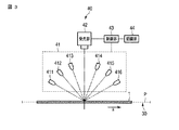
図3は、第1の実施形態に係る光検出装置40の例を示す。
光検出装置40は、紙葉類1の券面を撮像する。光検出装置40の光学センサは、例えば、Charge Coupled Device(CCD)などの受光素子と、光学系と、光源とを備える。光学センサは、搬送される紙葉類1に対して光源により光を投光し、反射光または透過光を光学系により受光する。光学センサは、光学系により受光した光をCCDに結像させ、電気信号(画像)を取得する。光検出装置40は、搬送路30により搬送される紙葉類1から連続して画像を取得することにより、紙葉類1の全体の画像を取得する。
FIG. 3 shows an example of the photodetecting device 40 according to the first embodiment.
The light detection device 40 images the bill surface of the paper sheet 1. The optical sensor of the light detection device 40 includes a light receiving element such as a charge coupled device (CCD), an optical system, and a light source. The optical sensor projects light onto the conveyed paper sheet 1 by a light source, and receives reflected light or transmitted light by an optical system. The optical sensor forms an image of light received by the optical system on the CCD, and acquires an electrical signal (image). The light detection device 40 acquires an entire image of the paper sheet 1 by continuously acquiring images from the paper sheet 1 conveyed by the conveyance path 30.

光検出装置40は、例えば紙葉類処理装置100の搬送路30の近傍に設置される。図3に示すように、光検出装置40は、照明部41、受光部42、制御部43、及び認識部44を備える。図3において認識装置は光検出装置と同じ場所に記載されているが、切り離されて設置される場合もある。搬送路30は、紙葉類1を矢印aの方向に所定の速度で搬送する。なお、紙葉類1が搬送される搬送路上の面を搬送面Pとする。   The light detection device 40 is installed in the vicinity of the conveyance path 30 of the paper sheet processing apparatus 100, for example. As shown in FIG. 3, the light detection device 40 includes an illumination unit 41, a light receiving unit 42, a control unit 43, and a recognition unit 44. In FIG. 3, the recognition device is described at the same place as the light detection device, but may be separated and installed. The conveyance path 30 conveys the paper sheet 1 in the direction of arrow a at a predetermined speed. A surface on the conveyance path on which the paper sheet 1 is conveyed is defined as a conveyance surface P.

制御部43は、光検出装置40の各部の動作を統合的に制御する。制御部43は、CPU、バッファメモリ、プログラムメモリ、及び不揮発性メモリなどを備える。CPUは、種々の演算処理を行う。バッファメモリは、CPUにより行われる演算の結果を一時的に記憶する。プログラムメモリ及び不揮発性メモリは、CPUが実行する種々のプログラム及び制御データなどを記憶する。制御部43は、CPUによりプログラムメモリに記憶されているプログラムを実行することにより、種々の処理を行うことができる。例えば、制御部43は、照明部41及び受光部42の動作のタイミングを制御する。   The control unit 43 controls the operation of each unit of the light detection device 40 in an integrated manner. The control unit 43 includes a CPU, a buffer memory, a program memory, a nonvolatile memory, and the like. The CPU performs various arithmetic processes. The buffer memory temporarily stores the results of calculations performed by the CPU. The program memory and the nonvolatile memory store various programs executed by the CPU, control data, and the like. The control unit 43 can perform various processes by executing a program stored in the program memory by the CPU. For example, the control unit 43 controls the operation timing of the illumination unit 41 and the light receiving unit 42.

なお、制御部43は、図1に示す主制御部50と通信を行うことができる。制御部43は、主制御部50から入力された制御信号に基づいて、照明部41及び受光部42を動作させる信号を生成する。   The control unit 43 can communicate with the main control unit 50 shown in FIG. The control unit 43 generates a signal for operating the illumination unit 41 and the light receiving unit 42 based on the control signal input from the main control unit 50.

照明部41は、搬送される紙葉類1に対して光を照射する。照明部41は、紙葉類1が搬送される搬送面Pに対してそれぞれ異なる角度で光を照射するように設置された複数の光源411乃至416を備える。   The illumination part 41 irradiates light with respect to the conveyed paper sheet 1. The illumination unit 41 includes a plurality of light sources 411 to 416 installed to irradiate light at different angles with respect to the transport surface P on which the paper sheet 1 is transported.

各光源411乃至416は、例えば、それぞれ、可視光を射出するLED、蛍光灯、または他の光源などを備える。各光源411乃至416は、それぞれ、受光部42の走査範囲に対して異なる角度で光を照射するように設置される。なお、光源411乃至416は、全ての光源411乃至416が点灯された場合、紙葉類1の表面の凹凸により陰影ができないように設置される。   Each of the light sources 411 to 416 includes, for example, an LED that emits visible light, a fluorescent lamp, or another light source. Each of the light sources 411 to 416 is installed so as to emit light at different angles with respect to the scanning range of the light receiving unit 42. Note that the light sources 411 to 416 are installed so as not to be shaded by the unevenness of the surface of the paper sheet 1 when all the light sources 411 to 416 are turned on.

受光部42は、所定の走査範囲(撮像範囲)を走査し、画像または光強度に応じた電気信号を取得する。すなわち、受光部42は、入射する光の光強度を検出値として検出する。受光部42は、例えば、CMOS、フォトダイオード、またはCCDなどの受光素子が線状に配列されたラインイメージセンサと、光を受光するレンズとを備える。また、受光部42は、例えば、照明部41から射出される光の波長に応じた特性を有するフィルタ(波長制限媒体)をさらに備えていてもよい。また、受光部42のラインイメージセンサは、所定の帯域の波長を感度領域とするセンサにより構成されていてもよい。   The light receiving unit 42 scans a predetermined scanning range (imaging range), and acquires an electrical signal corresponding to an image or light intensity. That is, the light receiving unit 42 detects the light intensity of incident light as a detection value. The light receiving unit 42 includes, for example, a line image sensor in which light receiving elements such as CMOS, photodiode, or CCD are arranged in a line, and a lens that receives light. The light receiving unit 42 may further include, for example, a filter (wavelength limiting medium) having characteristics corresponding to the wavelength of light emitted from the illumination unit 41. Further, the line image sensor of the light receiving unit 42 may be configured by a sensor having a wavelength in a predetermined band as a sensitivity region.

レンズは、上記の走査範囲から光を受光する。さらに、レンズは、走査範囲から受光した光をラインイメージセンサに結像させる。ラインイメージセンサは、受光した光を電気信号(画像)に変換する。   The lens receives light from the scanning range. Further, the lens causes the light received from the scanning range to form an image on the line image sensor. The line image sensor converts received light into an electrical signal (image).

図4は、照明部41の照明範囲、及び受光部42の走査範囲について示す。
紙葉類1は、図2に示したように、例えば矩形状の本体を有する。即ち、紙葉類1は、図4に示すように長手方向と短手方向(幅方向)とを有する。本実施形態では、紙葉類1は、長手方向に搬送される。
FIG. 4 shows the illumination range of the illumination unit 41 and the scanning range of the light receiving unit 42.
As shown in FIG. 2, the paper sheet 1 has, for example, a rectangular main body. That is, the paper sheet 1 has a longitudinal direction and a lateral direction (width direction) as shown in FIG. In the present embodiment, the paper sheet 1 is conveyed in the longitudinal direction.

図4に示されるように、受光部42の走査範囲は、紙葉類1の搬送方向と搬送面P上において直交する方向に延びるように形成される。なお、受光部42の走査範囲は、少なくとも紙葉類1の幅方向の長さより長く形成される。これにより、受光部42は、紙葉類1の全体から画像を取得することが出来る。   As shown in FIG. 4, the scanning range of the light receiving unit 42 is formed to extend in a direction orthogonal to the transport direction of the paper sheet 1 and the transport surface P. The scanning range of the light receiving unit 42 is formed to be at least longer than the length of the paper sheet 1 in the width direction. Thereby, the light receiving unit 42 can acquire an image from the entire paper sheet 1.

また、照明部41の照明範囲は、少なくとも受光部42の走査範囲を覆うように形成される。これにより、照明部41は、受光部42の走査範囲の全体に対して光を照射することができる。   The illumination range of the illumination unit 41 is formed so as to cover at least the scanning range of the light receiving unit 42. Thereby, the illuminating unit 41 can irradiate the entire scanning range of the light receiving unit 42 with light.

図3に示される制御部43は、受光部42により取得された紙葉類1の画像に対して信号処理を施し、宛先情報を認識する為の画像(宛先認識用画像)と、切手11及び窓枠12の位置を認識する為の画像(位置認識用画像)とを生成する。制御部43は、生成した宛先認識用画像と、位置認識用画像とを認識部44に出力する。   The control unit 43 shown in FIG. 3 performs signal processing on the image of the paper sheet 1 acquired by the light receiving unit 42, recognizes the destination information (destination recognition image), the stamp 11 and An image for recognizing the position of the window frame 12 (image for position recognition) is generated. The control unit 43 outputs the generated destination recognition image and position recognition image to the recognition unit 44.

認識部44は、種々の認識処理を行う。認識部44は、制御部43から供給された位置認識用画像に基づいて、切手11の位置及び窓枠12の位置を認識する。これにより、認識部44は、切手位置情報と、窓枠位置情報とを取得する。   The recognition unit 44 performs various recognition processes. The recognition unit 44 recognizes the position of the stamp 11 and the position of the window frame 12 based on the position recognition image supplied from the control unit 43. Thereby, the recognition unit 44 acquires stamp position information and window frame position information.

さらに、認識部44は、窓枠位置情報に基づいて、宛先認識用画像上に宛先情報を示す文字列が写り込んでいる範囲を特定する。認識部44は、特定した範囲の画像から文字を認識することにより、宛先情報を取得する。即ち、認識部44は、窓枠位置情報に基づいて、宛先認識用画像を切り出し、切り出した画像に対して文字認識処理を行うことにより、宛先情報を取得する。認識部44は、取得した切手位置情報及び宛先情報を主制御部50に供給する。   Further, the recognizing unit 44 specifies a range in which a character string indicating the destination information is reflected on the destination recognition image based on the window frame position information. The recognition unit 44 acquires destination information by recognizing characters from the image in the specified range. That is, the recognizing unit 44 cuts out the destination recognition image based on the window frame position information, and acquires the destination information by performing character recognition processing on the cut out image. The recognition unit 44 supplies the acquired stamp position information and destination information to the main control unit 50.

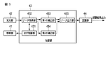
図5は、制御部43が有する機能について示す。
制御部43は、点灯制御部431、データ取得部432、第1の補正部433、第2の補正部434、及びデータ出力部435を備える。
FIG. 5 shows the functions of the control unit 43.
The control unit 43 includes a lighting control unit 431, a data acquisition unit 432, a first correction unit 433, a second correction unit 434, and a data output unit 435.

点灯制御部431は、照明部41の各光源411乃至416の点灯のタイミングを制御する。データ取得部432は、受光部42のラインイメージセンサにより画像を取得するタイミングを制御する。   The lighting control unit 431 controls lighting timing of the light sources 411 to 416 of the lighting unit 41. The data acquisition unit 432 controls the timing at which an image is acquired by the line image sensor of the light receiving unit 42.

例えば、点灯制御部431及びデータ取得部432は、図6に示されるタイミングチャートに基づいて、各光源411乃至416の点灯のタイミングと、受光部42のラインイメージセンサにより画像を取得するタイミングとを制御する。   For example, the lighting control unit 431 and the data acquisition unit 432 calculate the lighting timing of each of the light sources 411 to 416 and the timing of acquiring an image by the line image sensor of the light receiving unit 42 based on the timing chart shown in FIG. Control.

図6に示されるタイミングチャートに基づいて動作した場合、第1の光源411は、時間t1において点灯を開始し、時間t3において点灯を終了する。さらに、第1の光源411は、時間t9において点灯を開始し、時間t11において点灯を終了する。   When operating based on the timing chart shown in FIG. 6, the first light source 411 starts lighting at time t1 and ends lighting at time t3. Further, the first light source 411 starts lighting at time t9 and ends lighting at time t11.

また、第2の光源412、第3の光源413、第4の光源414、及び第5の光源415は、第1の光源411と同様に、時間t1において点灯を開始し、時間t3において点灯を終了し、時間t9において点灯を開始し、時間t11において点灯を終了する。光源411乃至415は、同様の点灯周期で以降の動作を行う。   Similarly to the first light source 411, the second light source 412, the third light source 413, the fourth light source 414, and the fifth light source 415 start lighting at time t1, and turn on at time t3. The lighting ends, lighting starts at time t9, and lighting ends at time t11. The light sources 411 to 415 perform the subsequent operations at the same lighting cycle.

また、図6に示されるタイミングチャートに基づいて動作した場合、第6の光源416は、時間t1において点灯を開始し、時間t3において点灯を終了する。さらに、第6の光源416は、時間t5において点灯を開始し、時間t7において点灯を終了する。またさらに、第6の光源416は、時間t9において点灯を開始し、時間t11において点灯を終了する。光源416は、同様の点灯周期で以降の動作を行う。   In addition, when operated based on the timing chart shown in FIG. 6, the sixth light source 416 starts lighting at time t1 and ends lighting at time t3. Further, the sixth light source 416 starts lighting at time t5 and ends lighting at time t7. Furthermore, the sixth light source 416 starts lighting at time t9 and ends lighting at time t11. The light source 416 performs the subsequent operations at the same lighting cycle.

また、図6に示されるタイミングチャートに基づいて動作した場合、受光部42は、時間t2において走査を開始し、時間t4において走査を終了する。これにより第1のラインの画像の取得が完了する。なお、時間t1から時間t3の間は、光源411乃至416が点灯している。即ち、受光部42は、光源411乃至416により照明された光の反射光に基づいて第1のラインの画像を取得する。   In addition, when operating based on the timing chart shown in FIG. 6, the light receiving unit 42 starts scanning at time t2 and ends scanning at time t4. Thereby, the acquisition of the image of the first line is completed. Note that the light sources 411 to 416 are turned on from the time t1 to the time t3. That is, the light receiving unit 42 acquires an image of the first line based on the reflected light of the light illuminated by the light sources 411 to 416.

光源411乃至416が点灯する場合、図7により示されるように、紙葉類1の表面の凹凸により陰影が生じない。受光部42は、光源411乃至416が点灯するタイミングで画像を取得することにより、宛先情報の認識に適した画像(宛先認識用画像)を取得することができる。   When the light sources 411 to 416 are turned on, as shown in FIG. 7, no shadow is generated due to the unevenness of the surface of the paper sheet 1. The light receiving unit 42 can acquire an image (destination recognition image) suitable for recognition of destination information by acquiring an image at the timing when the light sources 411 to 416 are turned on.

さらに、受光部42は、時間t6において走査を開始し、時間t8において走査を終了する。これにより第2のラインの画像の取得が完了する。なお、時間t5から時間t7の間は、光源411乃至415が消灯しており、光源416が点灯している。即ち、受光部42は、光源416により照明された光の反射光に基づいて第2のラインの画像を取得する。   Further, the light receiving unit 42 starts scanning at time t6 and ends scanning at time t8. Thereby, the acquisition of the image of the second line is completed. Note that during the period from time t5 to time t7, the light sources 411 to 415 are turned off and the light source 416 is turned on. That is, the light receiving unit 42 acquires an image of the second line based on the reflected light of the light illuminated by the light source 416.

光源416は、図8により示されるように、光源416から射出される光の光軸が紙葉類1と所定の角度を成すように設けられている。この為、光源416が単体で点灯する場合、図8により示されるように、紙葉類1の表面の凹凸により陰影が生じる。図8の例では、切手11により陰影が生じる例が示されている。受光部42は、光源416が単体で点灯するタイミングで画像を取得することにより、切手11及び窓枠12の位置を認識する為の画像(位置認識用画像)を取得することができる。 As shown in FIG. 8, the light source 416 is provided such that the optical axis of light emitted from the light source 416 forms a predetermined angle with the paper sheet 1. For this reason, when the light source 416 is lit alone, as shown in FIG. In the example of FIG. 8, an example in which a shadow is generated by the stamp 11 is shown. The light receiving unit 42 can acquire an image (position recognition image) for recognizing the positions of the stamp 11 and the window frame 12 by acquiring an image at the timing when the light source 416 is lit alone.

さらに、受光部42は、所定時間毎にスキャンを行うことにより、第3のライン、第4のライン、及び第Nのラインの画像を取得する。これにより、受光部42は、紙葉類1の全体から画像を取得する。   Furthermore, the light receiving unit 42 acquires images of the third line, the fourth line, and the Nth line by scanning at predetermined time intervals. As a result, the light receiving unit 42 acquires an image from the entire paper sheet 1.

図6に示されるタイミングチャートにしたがって動作する場合、受光部42は、奇数ラインの画像として、宛先認識用画像を取得する。また、受光部42は、偶数ラインの画像として、位置認識用画像を取得する。   When operating according to the timing chart shown in FIG. 6, the light receiving unit 42 acquires a destination recognition image as an image of odd lines. The light receiving unit 42 acquires a position recognition image as an even line image.

データ取得部432は、受光部42のラインイメージセンサにより取得した画像を第1の補正部433と第2の補正部434とに伝送する。例えば、データ取得部432は、宛先認識用画像を第1の補正部433に伝送し、位置認識用画像を第2の補正部434に伝送する。   The data acquisition unit 432 transmits the image acquired by the line image sensor of the light receiving unit 42 to the first correction unit 433 and the second correction unit 434. For example, the data acquisition unit 432 transmits the destination recognition image to the first correction unit 433 and transmits the position recognition image to the second correction unit 434.

第1の補正部433及び第2の補正部434は、それぞれ、データ取得部432から伝送された画像に対してシェイディング(shading)補正を行う。これにより、第1の補正部433及び第2の補正部434は、データ取得部432から伝送された画像の明るさを補正する。第1の補正部433及び第2の補正部434は、補正を施した画像をデータ出力部435に伝送する。データ出力部435は、第1の補正部433及び第2の補正部434から伝送された画像を認識部44に出力する。   The first correction unit 433 and the second correction unit 434 each perform shading correction on the image transmitted from the data acquisition unit 432. As a result, the first correction unit 433 and the second correction unit 434 correct the brightness of the image transmitted from the data acquisition unit 432. The first correction unit 433 and the second correction unit 434 transmit the corrected image to the data output unit 435. The data output unit 435 outputs the images transmitted from the first correction unit 433 and the second correction unit 434 to the recognition unit 44.

なお、第1の補正部433及び第2の補正部434は、それぞれ、異なる補正係数を用いてデータ取得部432から伝送された画像に対して補正を行う。例えば、第1の補正部433は、第1の補正係数を用いて補正を行い、第2の補正部434は、第2の補正係数を用いて補正を行う。   Note that the first correction unit 433 and the second correction unit 434 each correct the image transmitted from the data acquisition unit 432 using different correction coefficients. For example, the first correction unit 433 performs correction using the first correction coefficient, and the second correction unit 434 performs correction using the second correction coefficient.

第1の補正係数及び第2の補正係数は、第1の補正部433により補正が施された画像と、第2の補正部434により補正が施された画像とで明るさが同程度になる値に設定される。   The first correction coefficient and the second correction coefficient have the same brightness in the image corrected by the first correction unit 433 and the image corrected by the second correction unit 434. Set to a value.

なお、宛先認識用画像と位置認識用画像との明るさの差は、光源411乃至416が点灯した場合の照度と、光源416が単体で点灯した場合の照度と、に関係する。従って、第1の補正係数及び第2の補正係数は、光源411乃至416の照度に基づいて決定されてもよい。   Note that the difference in brightness between the destination recognition image and the position recognition image is related to the illuminance when the light sources 411 to 416 are lit and the illuminance when the light source 416 is lit alone. Therefore, the first correction coefficient and the second correction coefficient may be determined based on the illuminance of the light sources 411 to 416.

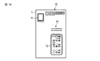
図9及び図10は、本実施形態の光検出装置40により取得された宛先認識用画像及び位置認識用画像の例を示す。図9は、宛先認識用画像の例を示す。図10は、位置認識用画像の例を示す。   9 and 10 show examples of destination recognition images and position recognition images acquired by the light detection device 40 of the present embodiment. FIG. 9 shows an example of a destination recognition image. FIG. 10 shows an example of the position recognition image.

図9に示されるように、宛先認識用画像は、陰影などが写りこまず、且つ、文字認識に適した明るさの画像である。また、図10に示されるように、位置認識用画像は、切手11及び窓枠12の位置の認識に適した画像である。位置認識用画像は、厚みを有する切手11の近傍、及び窓枠12内に生じた陰影を有する。   As shown in FIG. 9, the destination recognition image is an image that does not show shadows or the like and has a brightness suitable for character recognition. Also, as shown in FIG. 10, the position recognition image is an image suitable for recognizing the positions of the stamp 11 and the window frame 12. The position recognition image has shadows generated in the vicinity of the thick stamp 11 and in the window frame 12.

認識部44は、位置認識用画像の陰影に基づいて、切手11及び窓枠12の位置を認識する。即ち、認識部44は、位置認識用画像の陰影に基づいて、切手位置情報及び窓枠位置情報を取得する。   The recognition unit 44 recognizes the positions of the stamp 11 and the window frame 12 based on the shadow of the position recognition image. That is, the recognition unit 44 acquires stamp position information and window frame position information based on the shadow of the position recognition image.

さらに、認識部44は、窓枠位置情報に基づいて。宛先認識用画像上に宛先情報を示す文字列が写り込んでいる範囲を特定する。認識部44は、特定した範囲の画像から文字を認識することにより、宛先情報を取得する。   Furthermore, the recognition unit 44 is based on the window frame position information. A range in which a character string indicating the destination information is reflected on the destination recognition image is specified. The recognition unit 44 acquires destination information by recognizing characters from the image in the specified range.

例えば、認識部44は、予め設定されたテンプレートと位置認識用画像とでパターンマッチングを行うことにより、切手11及び窓枠12の位置を認識することができる。例えば、認識部44は、L字またはコの字の形状のテンプレートを予め記憶する。これにより、認識部44は、位置認識用画像上のL字またはコの字の形状のオブジェクトを検出することができる。例えば、認識部44は、検出したオブジェクトが矩形状となるように補完を行うことで、切手11及び窓枠12の位置を認識することができる。   For example, the recognition unit 44 can recognize the positions of the stamp 11 and the window frame 12 by performing pattern matching with a preset template and a position recognition image. For example, the recognition unit 44 stores an L-shaped or U-shaped template in advance. As a result, the recognition unit 44 can detect an L-shaped or U-shaped object on the position recognition image. For example, the recognition unit 44 can recognize the positions of the stamp 11 and the window frame 12 by performing complementation so that the detected object has a rectangular shape.

また、位置認識用画像には、図10により示される赤枠13、または線分14などが写り込む場合がある。赤枠13及び線分14などは、紙葉類1に印刷された模様などの印刷情報である。赤枠13及び線分14と上記のテンプレートの形状とが似ている場合、認識部44は、赤枠13及び線分14と、切手11及び窓枠12とを誤認識する可能性がある。そこで、認識部44は、宛先認識用画像と位置認識用画像との両方を用いて切手11及び窓枠12を認識する構成であってもよい。   Further, the position recognition image may include a red frame 13 or a line segment 14 shown in FIG. The red frame 13 and the line segment 14 are print information such as a pattern printed on the paper sheet 1. When the red frame 13 and the line segment 14 are similar to the shape of the template, the recognition unit 44 may erroneously recognize the red frame 13 and the line segment 14, the stamp 11, and the window frame 12. Therefore, the recognition unit 44 may be configured to recognize the stamp 11 and the window frame 12 using both the destination recognition image and the position recognition image.

この場合、認識部44は、宛先認識用画像と位置認識用画像との差異を検出し、検出された差異に基づいて切手11及び窓枠12の位置を認識する。この場合、赤枠13及び線分14は、宛先認識用画像と位置認識用画像との両方に写り込んでいる要素であり、差異から除外される。また、位置認識用画像の切手11及び窓枠12の近傍に生じた陰影は、宛先認識用画像には写りこんでいない要素であり、差異として検出される。認識部44は、検出された差異に基づいて切手11及び窓枠12の位置を認識することにより、より高い精度で切手11及び窓枠12の位置を認識することができる。   In this case, the recognition unit 44 detects a difference between the destination recognition image and the position recognition image, and recognizes the positions of the stamp 11 and the window frame 12 based on the detected difference. In this case, the red frame 13 and the line segment 14 are elements that are reflected in both the destination recognition image and the position recognition image, and are excluded from the difference. In addition, the shadow generated in the vicinity of the stamp 11 and the window frame 12 of the position recognition image is an element that is not reflected in the destination recognition image and is detected as a difference. The recognizing unit 44 can recognize the positions of the stamp 11 and the window frame 12 with higher accuracy by recognizing the positions of the stamp 11 and the window frame 12 based on the detected difference.

認識部44は、例えば、宛先認識用画像と位置認識用画像との論理積を算出し、算出した論理積を位置認識用画像から除算(または減算)することにより、宛先認識用画像と位置認識用画像との差異を検出する。   For example, the recognizing unit 44 calculates a logical product of the destination recognition image and the position recognition image, and divides (or subtracts) the calculated logical product from the position recognition image. The difference from the image is detected.

また、認識部44は、宛先認識用画像及び位置認識用画像からそれぞれ線分などの要素を検出し、検出された線分の幅の差に基づいて、宛先認識用画像と位置認識用画像との差異を検出する。   The recognizing unit 44 detects an element such as a line segment from each of the destination recognition image and the position recognition image, and based on the difference between the detected line segment widths, the destination recognition image and the position recognition image Detect differences in

上記したように、本実施形態に係る光検出装置40は、異なる角度で配置された複数の光源411及び416の点灯のタイミングと、受光部42の画像取得のタイミングとを制御する。これにより、光検出装置40は、紙葉類1の表面の凹凸に起因する陰影が写り込まない宛先認識用画像と、紙葉類1の表面の凹凸に起因する陰影が写り込んだ位置認識用画像と、を取得する。光検出装置40は、位置認識用画像に基づいて、切手位置情報と窓枠位置情報を取得する。さらに、光検出装置40は、窓枠位置情報と宛先認識用画像とに基づいて、宛先情報を取得する。   As described above, the light detection device 40 according to the present embodiment controls the lighting timing of the light sources 411 and 416 arranged at different angles and the image acquisition timing of the light receiving unit 42. As a result, the light detection device 40 uses the destination recognition image in which the shadow due to the unevenness on the surface of the paper sheet 1 does not appear and the position recognition image in which the shadow due to the unevenness on the surface of the paper sheet 1 appears. Get images and The light detection device 40 acquires stamp position information and window frame position information based on the position recognition image. Further, the light detection device 40 acquires destination information based on the window frame position information and the destination recognition image.

この構成によると、光検出装置40は、1つの受光部42(ラインイメージセンサ)を用いて宛先認識用画像と位置認識用画像とを取得することができる。この場合、宛先認識用画像と位置認識用画像とを1ラインずつ交互に取得している為、宛先認識用画像と位置認識用画像との間に位置のズレなどが生じることを防ぐことが出来る。この為、光検出装置40は、受光部42の設置を容易にすることができる。さらに、光検出装置40は、高い精度で切手位置情報及び宛先情報を取得することができる。   According to this configuration, the light detection device 40 can acquire a destination recognition image and a position recognition image using one light receiving unit 42 (line image sensor). In this case, since the destination recognition image and the position recognition image are alternately acquired line by line, it is possible to prevent a positional shift between the destination recognition image and the position recognition image. . Therefore, the light detection device 40 can easily install the light receiving unit 42. Furthermore, the photodetection device 40 can acquire stamp position information and destination information with high accuracy.

この結果、簡易な構成でより正確に位置検出を行うことができる光検出装置、及び光検出装置を備える紙葉類処理装置を提供することができる。   As a result, it is possible to provide a photodetection device capable of performing position detection more accurately with a simple configuration, and a paper sheet processing apparatus including the photodetection device.

なお、上記した実施形態では、光検出装置40は、宛先認識用画像と、位置認識用画像とを1ラインずつ交互に取得するとして説明したが、この構成に限定されない。光検出装置40は、宛先認識用画像と、位置認識用画像とを複数ラインずつ交互に取得する構成であってもよい。   In the above-described embodiment, the light detection device 40 has been described as alternately acquiring the destination recognition image and the position recognition image line by line, but is not limited to this configuration. The light detection device 40 may be configured to alternately acquire a destination recognition image and a position recognition image by a plurality of lines.

また、上記した実施形態では、光検出装置40は、奇数ラインで宛先認識用画像を取得し、偶数ラインで位置認識用画像を検出するとして説明したが、逆であってもよい。即ち、光検出装置40は、偶数ラインで宛先認識用画像を取得し、奇数ラインで位置認識用画像を検出する構成であってもよい。   In the above-described embodiment, the light detection device 40 has been described as acquiring a destination recognition image with an odd number of lines and detecting a position recognition image with an even number of lines. In other words, the light detection device 40 may be configured to acquire a destination recognition image using even lines and detect a position recognition image using odd lines.

またさらに、上記した実施形態では、光検出装置40は、第1の補正部433及び第2の補正部434により宛先認識用画像と位置認識用画像とが同じ明るさになるように補正すると説明したが、この構成に限定されない。光検出装置40は、点灯制御部431により光源411乃至416の発光強度を制御する構成であってもよい。   Furthermore, in the above-described embodiment, it is described that the light detection device 40 corrects the destination recognition image and the position recognition image to have the same brightness by the first correction unit 433 and the second correction unit 434. However, it is not limited to this configuration. The light detection device 40 may be configured to control the light emission intensity of the light sources 411 to 416 by the lighting control unit 431.

またさらに、上記した実施形態では、照明部41は、6個の光源を備える構成として説明したが、この構成に限定されない。光源の数は、紙葉類1の凹凸に起因する陰影が生じないように照明する事ができる数であれば、如何なる数であってもよい。   Furthermore, in the above-described embodiment, the illumination unit 41 has been described as a configuration including six light sources, but is not limited to this configuration. The number of light sources may be any number as long as it can be illuminated so as not to cause a shadow due to the unevenness of the paper sheet 1.

この場合、光検出装置40は、図6に示される時間t5からt7の間に、光源416を強い発光強度で発光させることにより、同程度の明るさの宛先認識用画像及び位置認識用画像を取得することが出来る。例えば、光検出装置40は、宛先認識用画像を取得するタイミングと、位置認識用画像を取得するタイミングとで、受光部42の走査範囲における照度が同程度になるように光源411乃至416の発光強度を制御する。   In this case, the light detection device 40 causes the light source 416 to emit light with strong light emission intensity between times t5 and t7 shown in FIG. Can be acquired. For example, the light detection device 40 emits light from the light sources 411 to 416 so that the illuminance in the scanning range of the light receiving unit 42 is approximately the same at the timing of acquiring the destination recognition image and the timing of acquiring the position recognition image. Control strength.

(第2の実施形態)
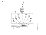
図11は、第2の実施形態に係る光検出装置40の例を示す。なお、第1の実施形態と同様の構成には同じ参照符号を付し、その詳細な説明を省略する。
光検出装置40は、例えば紙葉類処理装置100の搬送路30の近傍に設置される。図11に示すように、光検出装置40は、照明部45、受光部42、制御部43、及び認識部44を備える。搬送路30は、紙葉類1を矢印aの方向に所定の速度で搬送する。なお、紙葉類1が搬送される搬送路上の面を搬送面Pとする。
(Second Embodiment)
FIG. 11 shows an example of the photodetection device 40 according to the second embodiment. The same components as those in the first embodiment are denoted by the same reference numerals, and detailed description thereof is omitted.
The light detection device 40 is installed in the vicinity of the conveyance path 30 of the paper sheet processing apparatus 100, for example. As shown in FIG. 11, the light detection device 40 includes an illumination unit 45, a light receiving unit 42, a control unit 43, and a recognition unit 44. The conveyance path 30 conveys the paper sheet 1 in the direction of arrow a at a predetermined speed. A surface on the conveyance path on which the paper sheet 1 is conveyed is defined as a conveyance surface P.

照明部45は、搬送される紙葉類1に対して光を照射する。照明部45は、紙葉類1が搬送される搬送面Pに対してそれぞれ異なる角度で光を照射するように設置された複数の光源451乃至456を備える。   The illumination part 45 irradiates light with respect to the conveyed paper sheet 1. The illumination unit 45 includes a plurality of light sources 451 to 456 installed to irradiate light at different angles with respect to the transport surface P on which the paper sheet 1 is transported.

光源451、光源453、及び光源455は、例えば、それぞれ、白色などのブロードな帯域の光を射出するLED、蛍光灯、または他の光源などを備える。光源451、光源453、及び光源455は、それぞれ、受光部42の走査範囲に対して異なる角度で光を照射するように設置される。なお、光源451、光源453、及び光源455は、光源451、光源453、及び光源455が全て点灯された場合、紙葉類1の表面の凹凸により陰影ができないように設置される。   The light source 451, the light source 453, and the light source 455 each include, for example, an LED, a fluorescent lamp, or another light source that emits light in a broad band such as white. The light source 451, the light source 453, and the light source 455 are each installed so as to emit light at different angles with respect to the scanning range of the light receiving unit 42. Note that the light source 451, the light source 453, and the light source 455 are installed so as not to be shaded by unevenness on the surface of the paper sheet 1 when all of the light source 451, the light source 453, and the light source 455 are turned on.

光源452、光源454、及び光源456は、例えば、それぞれ、赤色の波長の光を射出するLED、蛍光灯、または他の光源などを備える。光源452、光源454、及び光源456は、それぞれ、受光部42の走査範囲に対して異なる角度で光を照射するように設置される。なお、光源452、光源454、及び光源456は、光源452、光源454、及び光源456が全て点灯された場合、紙葉類1の表面の凹凸により陰影ができないように設置される。   The light source 452, the light source 454, and the light source 456 include, for example, an LED, a fluorescent lamp, or another light source that emits light having a red wavelength. The light source 452, the light source 454, and the light source 456 are each installed so as to emit light at different angles with respect to the scanning range of the light receiving unit 42. Note that the light source 452, the light source 454, and the light source 456 are installed so as not to be shaded by the unevenness of the surface of the paper sheet 1 when the light source 452, the light source 454, and the light source 456 are all turned on.

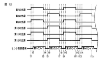
制御部43は、図12に示されるタイミングチャートに基づいて、各光源451乃至456の点灯のタイミングと、受光部42のラインイメージセンサにより画像を取得するタイミングとを制御する。   Based on the timing chart shown in FIG. 12, the control unit 43 controls the lighting timing of each of the light sources 451 to 456 and the timing at which an image is acquired by the line image sensor of the light receiving unit 42.

図12に示されるタイミングチャートに基づいて動作した場合、第7の光源451、第9の光源453、及び第11の光源455は、時間t1において点灯を開始し、時間t3において点灯を終了する。さらに、第7の光源451、第9の光源453、及び第11の光源455は、時間t9において点灯を開始し、時間t11において点灯を終了する。第7の光源451、第9の光源453、及び第11の光源455は、同様の点灯周期で以降の動作を行う。   When operating based on the timing chart shown in FIG. 12, the seventh light source 451, the ninth light source 453, and the eleventh light source 455 start lighting at time t1, and end lighting at time t3. Further, the seventh light source 451, the ninth light source 453, and the eleventh light source 455 start lighting at time t9 and end lighting at time t11. The seventh light source 451, the ninth light source 453, and the eleventh light source 455 perform the subsequent operations at the same lighting cycle.

また、第8の光源452、第10の光源454、及び第12の光源456は、時間t5において点灯を開始し、時間t7において点灯を終了し、時間t13において点灯を開始し、時間t15において点灯を終了する。第8の光源452、第10の光源454、及び第12の光源456は、同様の点灯周期で以降の動作を行う。   In addition, the eighth light source 452, the tenth light source 454, and the twelfth light source 456 start lighting at time t5, end lighting at time t7, start lighting at time t13, and light at time t15. Exit. The eighth light source 452, the tenth light source 454, and the twelfth light source 456 perform the following operations with the same lighting cycle.

第7の光源451、第9の光源453、及び第11の光源455が点灯する場合、紙葉類1の表面の凹凸により陰影が生じない。受光部42は、第7の光源451、第9の光源453、及び第11の光源455が点灯するタイミングで画像を取得することにより、宛先情報の認識に適した画像(宛先認識用画像)を取得することができる。即ち、光検出装置40は、図9に示される画像と同様の画像を取得することが出来る。   When the seventh light source 451, the ninth light source 453, and the eleventh light source 455 are turned on, no shading occurs due to the unevenness of the surface of the paper sheet 1. The light receiving unit 42 acquires an image (destination recognition image) suitable for recognition of destination information by acquiring an image when the seventh light source 451, the ninth light source 453, and the eleventh light source 455 are turned on. Can be acquired. That is, the light detection device 40 can acquire an image similar to the image shown in FIG.

また、第8の光源452、第10の光源454、及び第12の光源456が点灯する場合、紙葉類1の表面の凹凸により陰影が生じない。さらに、第8の光源452、第10の光源454、及び第12の光源456は、赤色の波長の光を照射する光源である。この為、受光部42は、第8の光源452、第10の光源454、及び第12の光源456が点灯するタイミングで画像を取得することにより、紙葉類1上の赤色で印刷された模様(赤色要素)が除去された画像(赤色除去画像)を取得することができる。   Further, when the eighth light source 452, the tenth light source 454, and the twelfth light source 456 are turned on, no shadow is generated due to the unevenness of the surface of the paper sheet 1. Further, the eighth light source 452, the tenth light source 454, and the twelfth light source 456 are light sources that emit light having a red wavelength. For this reason, the light receiving unit 42 obtains an image at the timing when the eighth light source 452, the tenth light source 454, and the twelfth light source 456 are turned on, so that the pattern printed in red on the paper sheet 1 is printed. An image (red-removed image) from which (red element) has been removed can be acquired.

さらに、受光部42は、所定時間毎にスキャンを行うことにより、第3のライン、第4のライン、及び第Nのラインの画像を取得する。これにより、受光部42は、紙葉類1の全体から画像を取得する。   Furthermore, the light receiving unit 42 acquires images of the third line, the fourth line, and the Nth line by scanning at predetermined time intervals. As a result, the light receiving unit 42 acquires an image from the entire paper sheet 1.

図12に示されるタイミングチャートにしたがって動作する場合、受光部42は、奇数ラインの画像として、宛先認識用画像を取得する。また、受光部42は、偶数ラインの画像として、赤色除去画像を取得する。   When operating according to the timing chart shown in FIG. 12, the light receiving unit 42 acquires a destination recognition image as an image of odd lines. In addition, the light receiving unit 42 acquires a red-removed image as an even line image.

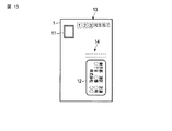
図13は、本実施形態の光検出装置40により取得された赤色除去画像の例を示す。
図13に示されるように、赤色除去画像は、紙葉類1上において赤色で印刷された模様が写りこまない。この為、例えば、赤枠13内に郵便番号などが記載されている場合、認識部44は、赤色除去画像に基づいて文字認識を行うことにより、容易に郵便番号を取得することができる。また、例えば、線分14が赤色で紙葉類1に印刷されている場合、光検出装置40は、図13に示されるように線分14が除去された画像を取得することができる。
FIG. 13 shows an example of a red-removed image acquired by the light detection device 40 of this embodiment.
As shown in FIG. 13, in the red-removed image, a pattern printed in red on the paper sheet 1 does not appear. For this reason, for example, when a zip code or the like is written in the red frame 13, the recognition unit 44 can easily acquire the zip code by performing character recognition based on the red-removed image. For example, when the line segment 14 is red and printed on the paper sheet 1, the light detection device 40 can acquire an image from which the line segment 14 is removed as illustrated in FIG. 13.

上記したように、本実施形態に係る光検出装置40は、白色などのブロードな帯域の光と、赤色光とを交互のタイミングで紙葉類1に照射する。光検出装置40は、各タイミングで画像を取得することにより、宛先認識用画像と赤色除去画像とを取得することができる。これにより、光検出装置40は、赤枠13内に記載されている郵便番号などを容易に認識することができる。   As described above, the light detection device 40 according to the present embodiment irradiates the paper sheet 1 with light in a broad band such as white and red light at alternate timings. The light detection device 40 can acquire the destination recognition image and the red color removal image by acquiring the image at each timing. Thereby, the photodetection device 40 can easily recognize the postal code or the like written in the red frame 13.

なお、上気した実施形態では、光検出装置40は、白色などのブロードな帯域の光と、赤色光とを交互のタイミングで紙葉類1に照射し、宛先認識用画像と赤色除去画像とを取得すると説明したが、この構成に限定されない。さらに第1の実施例の構成を組み合わせても良い。   In the above-described embodiment, the light detection device 40 irradiates the paper sheet 1 with light in a broad band such as white and red light at alternate timings, and the destination recognition image and the red-removed image are displayed. However, the present invention is not limited to this configuration. Furthermore, the configuration of the first embodiment may be combined.

即ち、光検出装置40は、白色などのブロードな帯域の光を照射するタイミングと、赤色光を照射するタイミングと、陰影ができるように光を照射するタイミングとを制御する。さらに、光検出装置40は、各タイミングにおいて画像を取得する。これにより、光検出装置40は、紙葉類1の表面の凹凸に起因する陰影が写り込まない宛先認識用画像と、紙葉類1の表面の凹凸に起因する陰影が写り込んだ位置認識用画像と、赤色要素が除去された赤色除去画像とを取得することができる。   That is, the light detection device 40 controls the timing of irradiating light in a broad band such as white, the timing of irradiating red light, and the timing of irradiating light so as to create a shadow. Furthermore, the photodetection device 40 acquires an image at each timing. As a result, the light detection device 40 uses the destination recognition image in which the shadow due to the unevenness on the surface of the paper sheet 1 does not appear and the position recognition image in which the shadow due to the unevenness on the surface of the paper sheet 1 appears. An image and a red-removed image from which red elements have been removed can be acquired.

これにより、光検出装置40は、位置認識用画像に基づいて、切手位置情報と窓枠位置情報を取得することができる。さらに、光検出装置40は、窓枠位置情報と宛先認識用画像とに基づいて、宛先情報を取得する。またさらに、光検出装置40は、赤色除去画像に基づいて、郵便番号などを容易に取得することができる。この結果、簡易な構成でより正確に位置検出を行うことができる光検出装置、及び光検出装置を備える紙葉類処理装置を提供することができる。   Thereby, the photodetection device 40 can acquire stamp position information and window frame position information based on the position recognition image. Further, the light detection device 40 acquires destination information based on the window frame position information and the destination recognition image. Still further, the light detection device 40 can easily obtain a zip code or the like based on the red color removal image. As a result, it is possible to provide a photodetection device capable of performing position detection more accurately with a simple configuration, and a paper sheet processing apparatus including the photodetection device.

なお、上述の各実施の形態で説明した機能は、ハードウエアを用いて構成するに留まらず、ソフトウエアを用いて各機能を記載したプログラムをコンピュータに読み込ませて実現することもできる。また、各機能は、適宜ソフトウエア、ハードウエアのいずれかを選択して構成するものであっても良い。   It should be noted that the functions described in the above embodiments are not limited to being configured using hardware, but can be realized by causing a computer to read a program describing each function using software. Each function may be configured by appropriately selecting either software or hardware.

なお、本発明は上記実施形態そのままに限定されるものではなく、実施段階ではその要旨を逸脱しない範囲で構成要素を変形して具体化できる。また、上記実施形態に開示されている複数の構成要素の適宜な組み合せにより種々の発明を形成できる。例えば、実施形態に示される全構成要素から幾つかの構成要素を削除してもよい。更に、異なる実施形態に亘る構成要素を適宜組み合せてもよい。   Note that the present invention is not limited to the above-described embodiment as it is, and can be embodied by modifying the constituent elements without departing from the scope of the invention in the implementation stage. Further, various inventions can be formed by appropriately combining a plurality of constituent elements disclosed in the embodiment. For example, some components may be deleted from all the components shown in the embodiment. Furthermore, you may combine suitably the component covering different embodiment.

1…紙葉類、11…切手、12…窓枠、13…赤枠、14…線分、20…供給部、25…分離ローラ、30…搬送路、40…光検出装置、41…照明部、42…受光部、43…制御部、44…認識部、45…照明部、46…押印部、47…印刷部、50…主制御部、60…区分処理部、70…操作部、80…表示部、90…入出力部、100…紙葉類処理装置、411乃至416…光源、431…点灯制御部、432…データ取得部、433…第1の補正部、434…第2の補正部、435…データ出力部、451乃至456…光源。   DESCRIPTION OF SYMBOLS 1 ... Paper sheet, 11 ... Stamp, 12 ... Window frame, 13 ... Red frame, 14 ... Line segment, 20 ... Supply part, 25 ... Separation roller, 30 ... Conveyance path, 40 ... Light detection apparatus, 41 ... Illumination part , 42 ... light receiving part, 43 ... control part, 44 ... recognition part, 45 ... illumination part, 46 ... stamping part, 47 ... printing part, 50 ... main control part, 60 ... classification processing part, 70 ... operation part, 80 ... Display unit 90 ... Input / output unit 100 ... Paper sheet processing apparatus 411 to 416 ... Light source 431 ... Lighting control unit 432 ... Data acquisition unit 433 ... First correction unit 434 ... Second correction unit 435, data output unit, 451 to 456, light source.

Claims (10)

搬送される紙葉類に対して光を照射する第1の照明部と、第2の照明部と、を有する照明部と、
前記紙葉類が搬送される搬送面上の走査範囲から光を受光する受光部と、
前記受光部により受光された光に基づいて画像を取得する画像取得部と、
前記照明部の前記第1の照明部が点灯している場合に前記画像取得部により第1の画像を取得し、前記照明部の前記第2の照明部が点灯している場合に前記画像取得部により第2の画像を取得するように前記画像取得部を制御する制御部と、
を具備し、
前記第1の照明部は、光軸が前記紙葉類に対して所定の角度を成すように設けられた第1の光源と、前記受光部の光軸に対して前記第1の光源と対向する位置に設けられた第2の光源とを有し、
前記第2の照明部は、前記第1の光源と前記第2の光源とのうちのいずれか1つを有する、
光検出装置。
An illumination unit having a first illumination unit that irradiates light to the conveyed paper sheet, and a second illumination unit;
A light receiving unit that receives light from a scanning range on a conveyance surface on which the paper sheet is conveyed;
An image acquisition unit for acquiring an image based on the light received by the light receiving unit;
The first image is acquired by the image acquisition unit when the first illumination unit of the illumination unit is turned on, and the image acquisition is performed when the second illumination unit of the illumination unit is turned on. A control unit that controls the image acquisition unit to acquire a second image by the unit;
Comprising
The first illumination unit is opposed to the first light source provided such that an optical axis forms a predetermined angle with respect to the paper sheet, and the first light source opposed to the optical axis of the light receiving unit. A second light source provided at a position to
The second illuminating unit includes any one of the first light source and the second light source.
Photodetector.
前記第2の光源は、前記受光部の光軸に対して前記第1の光源と対称な位置に設けられる、請求項1に記載の光検出装置。   The light detection device according to claim 1, wherein the second light source is provided at a position symmetrical to the first light source with respect to an optical axis of the light receiving unit. 前記制御部は、前記第1の照明部と、前記第2の照明部とが所定間隔で交互に点灯するように前記照明部を制御する請求項3に記載の光検出装置。   The said control part is a photon detection apparatus of Claim 3 which controls the said illumination part so that the said 1st illumination part and the said 2nd illumination part may light alternately by predetermined space | interval. 前記第2の画像に基づいて、窓枠の位置を認識する認識部をさらに具備する請求項3に記載の光検出装置。   The light detection device according to claim 3, further comprising a recognition unit that recognizes a position of a window frame based on the second image. 前記認識部は、認識された前記窓枠の位置と、前記第1の画像とに基づいて、前記紙葉類の宛先情報を認識する、請求項4に記載の光検出装置。   The light detection device according to claim 4, wherein the recognition unit recognizes destination information of the paper sheet based on the recognized position of the window frame and the first image. 前記第2の画像に基づいて、切手が貼付されている位置を認識する認識部をさらに具備する請求項5に記載の光検出装置。   The light detection device according to claim 5, further comprising a recognition unit that recognizes a position where a stamp is pasted based on the second image. 前記制御部は、前記第1の照明部から射出された光の照度と、前記第2の照明部から射出された光の照度とが、前記受光部の前記走査範囲内において同じになるように前記照明部を制御する請求項3に記載の光検出装置。   The control unit is configured such that the illuminance of light emitted from the first illumination unit and the illuminance of light emitted from the second illumination unit are the same within the scanning range of the light receiving unit. The light detection device according to claim 3, wherein the light control unit is controlled. 前記制御部は、
前記第1の画像に対して第1の補正係数を用いて補正を行う第1の補正部と、
前記第2の画像に対して第2の補正係数を用いて補正を行う第2の補正部と、
を具備する、請求項3に記載の光検出装置。
The controller is
A first correction unit that performs correction on the first image using a first correction coefficient;
A second correction unit that corrects the second image using a second correction coefficient;
The photodetection device according to claim 3, comprising:
前記画像取得部により取得された画像に基づいて郵便番号を認識する認識部をさらに具備し、
前記照明部は、搬送される紙葉類に対して赤色の波長の光を照射する第3の照明部を具備し、
前記制御部は、前記第3の照明部が点灯している場合に前記画像取得部により第3の画像を取得し、
前記認識部は、前記第3の画像に基づいて郵便番号を認識する、
請求項3に記載の光検出装置。
Further comprising a recognition unit for recognizing a zip code based on the image acquired by the image acquisition unit;
The illuminating unit includes a third illuminating unit that irradiates the transported paper sheet with light having a red wavelength,
The control unit acquires a third image by the image acquisition unit when the third illumination unit is lit,
The recognizing unit recognizes a zip code based on the third image;
The photodetection device according to claim 3.
紙葉類を搬送する搬送部と、
前記搬送部により搬送される前記紙葉類に対して光を照射する第1の照明部と、第2の照明部と、を有する照明部と、
前記紙葉類が搬送される搬送面上の走査範囲から光を受光する受光部と、
前記受光部により受光された光に基づいて画像を取得する画像取得部と、
前記照明部の前記第1の照明部が点灯している場合に前記画像取得部により第1の画像を取得し、前記照明部の前記第2の照明部が点灯している場合に前記画像取得部により第2の画像を取得するように前記画像取得部を制御する制御部と、
前記第2の画像に基づいて、窓枠の位置を認識し、認識された前記窓枠の位置と、前記第1の画像とに基づいて、前記紙葉類の宛先情報を認識する認識部と、
前記認識部により認識された前記宛先情報に基づいて、前記紙葉類を区分する区分処理部と、
を具備し、
前記第1の照明部は、光軸が前記紙葉類に対して所定の角度を成すように設けられた第1の光源と、前記受光部の光軸に対して前記第1の光源と対向する位置に設けられた第2の光源とを有し、
前記第2の照明部は、前記第1の光源と前記第2の光源とのうちのいずれか1つを有する、
紙葉類処理装置。
A transport unit for transporting paper sheets;
An illumination unit having a first illumination unit that irradiates light to the paper sheet conveyed by the conveyance unit; and a second illumination unit;
A light receiving unit that receives light from a scanning range on a conveyance surface on which the paper sheet is conveyed;
An image acquisition unit for acquiring an image based on the light received by the light receiving unit;
The first image is acquired by the image acquisition unit when the first illumination unit of the illumination unit is turned on, and the image acquisition is performed when the second illumination unit of the illumination unit is turned on. A control unit that controls the image acquisition unit to acquire a second image by the unit;
A recognition unit that recognizes a position of a window frame based on the second image, and recognizes destination information of the paper sheet based on the recognized position of the window frame and the first image; ,
A sorting processing unit for sorting the paper sheets based on the destination information recognized by the recognition unit;
Comprising
The first illumination unit is opposed to the first light source provided such that an optical axis forms a predetermined angle with respect to the paper sheet, and the first light source opposed to the optical axis of the light receiving unit. A second light source provided at a position to
The second illuminating unit includes any one of the first light source and the second light source.
Paper sheet processing equipment.
JP2011061696A 2011-03-18 2011-03-18 Light detection device and paper sheet processor including light detection device Pending JP2012198700A (en)

Priority Applications (1)

Application Number Priority Date Filing Date Title
JP2011061696A JP2012198700A (en) 2011-03-18 2011-03-18 Light detection device and paper sheet processor including light detection device

Applications Claiming Priority (1)

Application Number Priority Date Filing Date Title
JP2011061696A JP2012198700A (en) 2011-03-18 2011-03-18 Light detection device and paper sheet processor including light detection device

Publications (1)

Publication Number Publication Date
JP2012198700A true JP2012198700A (en) 2012-10-18

Family

ID=47180863

Family Applications (1)

Application Number Title Priority Date Filing Date
JP2011061696A Pending JP2012198700A (en) 2011-03-18 2011-03-18 Light detection device and paper sheet processor including light detection device

Country Status (1)

Country Link
JP (1) JP2012198700A (en)

Cited By (4)

* Cited by examiner, † Cited by third party
Publication number Priority date Publication date Assignee Title
WO2016021145A1 (en) * 2014-08-04 2016-02-11 パナソニックIpマネジメント株式会社 Electronic locker
JP2016112040A (en) * 2014-12-11 2016-06-23 富士通株式会社 Bed area extraction method, bed area extraction device and bed area extraction program
JP2016177754A (en) * 2015-03-23 2016-10-06 日本電気株式会社 Character extraction device, character extraction method, and character extraction program
CN106855948A (en) * 2016-12-13 2017-06-16 深圳市海云天科技股份有限公司 It is a kind of to detect that answering card scanning produces the method and device of secondary pollution

Citations (3)

* Cited by examiner, † Cited by third party
Publication number Priority date Publication date Assignee Title
JPS6241118A (en) * 1985-08-16 1987-02-23 Toshiba Corp Cargo sorting device
JPH11179288A (en) * 1997-09-16 1999-07-06 Toshiba Corp Level detector and treating device using the same
JP2010277252A (en) * 2009-05-27 2010-12-09 Toshiba Corp Paper sheet handling apparatus

Patent Citations (3)

* Cited by examiner, † Cited by third party
Publication number Priority date Publication date Assignee Title
JPS6241118A (en) * 1985-08-16 1987-02-23 Toshiba Corp Cargo sorting device
JPH11179288A (en) * 1997-09-16 1999-07-06 Toshiba Corp Level detector and treating device using the same
JP2010277252A (en) * 2009-05-27 2010-12-09 Toshiba Corp Paper sheet handling apparatus

Cited By (6)

* Cited by examiner, † Cited by third party
Publication number Priority date Publication date Assignee Title
WO2016021145A1 (en) * 2014-08-04 2016-02-11 パナソニックIpマネジメント株式会社 Electronic locker
JPWO2016021145A1 (en) * 2014-08-04 2017-05-18 パナソニックIpマネジメント株式会社 Electronic locker
US10242522B2 (en) 2014-08-04 2019-03-26 Panasonic Intellectual Property Management Co., Ltd. Electronic locker
JP2016112040A (en) * 2014-12-11 2016-06-23 富士通株式会社 Bed area extraction method, bed area extraction device and bed area extraction program
JP2016177754A (en) * 2015-03-23 2016-10-06 日本電気株式会社 Character extraction device, character extraction method, and character extraction program
CN106855948A (en) * 2016-12-13 2017-06-16 深圳市海云天科技股份有限公司 It is a kind of to detect that answering card scanning produces the method and device of secondary pollution

Similar Documents

Publication Publication Date Title
US8199379B2 (en) Optical detection apparatus, and sheet processing apparatus having the optical detection apparatus
US8558205B2 (en) Light detection device and sheet processing apparatus including the same
JP5989475B2 (en) Image reading apparatus and paper sheet processing apparatus
JP2012198700A (en) Light detection device and paper sheet processor including light detection device
US5847405A (en) Size or position sensing of intermixed sheets in a sheet stacking tray with sheet edge shadow detection
JP2013070163A (en) Image reading device, image forming device, and image reading program
US9936093B2 (en) Image reading apparatus and sheet processing apparatus
JP5968042B2 (en) Conveying apparatus and image forming apparatus
JP5180054B2 (en) Image reading apparatus, image reading system, and contour detection method
JP2020046972A (en) Paper sheet processing apparatus and paper sheet processing method
CN109074697B (en) Paper sheet identification device and paper sheet identification method
US20230015962A1 (en) Optical sensor and sheet recognition unit
CN107317950B (en) Photosensitive equipment with inclined background film and photosensitive method thereof
JP7110948B2 (en) Medium conveying device and image reading device
JP5935687B2 (en) Image reading device
JPH0830785A (en) Stamp detector
JP7308030B2 (en) Image processing device
JP2001232304A (en) Paper sheets processing device and paper sheets processing method
JP2013061765A (en) Paper sheet handling device and paper sheet handling method
JP2005295407A (en) Image reader, and image forming apparatus
JP2013197689A (en) Image reader and paper sheet processor
JP2011066712A (en) Image input device, sorting device, stamper and method of adjusting the image input device
JP2014063339A (en) Character reader
JP2011095795A (en) Device and method for reading voting sheet
JP2013198084A (en) Image reader, image forming apparatus and original end detecting method

Legal Events

Date Code Title Description
A621 Written request for application examination

Free format text: JAPANESE INTERMEDIATE CODE: A621

Effective date: 20130529

RD04 Notification of resignation of power of attorney

Free format text: JAPANESE INTERMEDIATE CODE: A7424

Effective date: 20131205

RD04 Notification of resignation of power of attorney

Free format text: JAPANESE INTERMEDIATE CODE: A7424

Effective date: 20131212

RD04 Notification of resignation of power of attorney

Free format text: JAPANESE INTERMEDIATE CODE: A7424

Effective date: 20131219

RD04 Notification of resignation of power of attorney

Free format text: JAPANESE INTERMEDIATE CODE: A7424

Effective date: 20131226

RD04 Notification of resignation of power of attorney

Free format text: JAPANESE INTERMEDIATE CODE: A7424

Effective date: 20140109

A977 Report on retrieval

Free format text: JAPANESE INTERMEDIATE CODE: A971007

Effective date: 20140123

A131 Notification of reasons for refusal

Free format text: JAPANESE INTERMEDIATE CODE: A131

Effective date: 20140212

A02 Decision of refusal

Free format text: JAPANESE INTERMEDIATE CODE: A02

Effective date: 20140701