JP2012197983A - Storage type water heater - Google Patents

Storage type water heater Download PDF

Info

Publication number
JP2012197983A
JP2012197983A JP2011062637A JP2011062637A JP2012197983A JP 2012197983 A JP2012197983 A JP 2012197983A JP 2011062637 A JP2011062637 A JP 2011062637A JP 2011062637 A JP2011062637 A JP 2011062637A JP 2012197983 A JP2012197983 A JP 2012197983A
Authority
JP
Japan
Prior art keywords
hot water
heat insulating
insulating material
pump
water storage
Prior art date
Legal status (The legal status is an assumption and is not a legal conclusion. Google has not performed a legal analysis and makes no representation as to the accuracy of the status listed.)
Withdrawn
Application number
JP2011062637A
Other languages
Japanese (ja)
Inventor
Junya Yamamoto
純也 山本
Masayuki Sudo
真行 須藤
Tadaaki Yanagi
忠明 柳
Current Assignee (The listed assignees may be inaccurate. Google has not performed a legal analysis and makes no representation or warranty as to the accuracy of the list.)
Mitsubishi Electric Corp
Original Assignee
Mitsubishi Electric Corp
Priority date (The priority date is an assumption and is not a legal conclusion. Google has not performed a legal analysis and makes no representation as to the accuracy of the date listed.)
Filing date
Publication date
Application filed by Mitsubishi Electric Corp filed Critical Mitsubishi Electric Corp
Priority to JP2011062637A priority Critical patent/JP2012197983A/en
Publication of JP2012197983A publication Critical patent/JP2012197983A/en
Withdrawn legal-status Critical Current

Links

Images

Landscapes

  • Details Of Fluid Heaters (AREA)
  • Heat-Pump Type And Storage Water Heaters (AREA)

Abstract

PROBLEM TO BE SOLVED: To provide a storage type water heater with a vibration control structure achieved with a simple structure.SOLUTION: The storage type water heater includes: a hot water storage tank 3 for storing hot water; and a bath circulation pump 8 for delivering hot water. The storage type water heater is equipped with: heat insulating materials 31, 32 formed in such a shape so as to cover the hot water storage tank 3; an insertion heat-insulating-material 34 which is insertion-fitted and fixed in a heat-insulating-material cutout part 35 formed in the heat insulating materials 31, 32; and a pump support structure 54 fixed to the insertion heat-insulating-material 34. The pump support structure 54: has a pump installation part 542 where the bath circulation pump 8 is installed; and is formed in such a way that the pump installation part 542 protrudes outside when the insertion heat-insulating-material 34 is insertion-fitted in the heat insulating materials 31, 32.

Description

この発明は、貯湯式給湯機に関する。   The present invention relates to a hot water storage type water heater.

従来、貯湯式給湯機においては、貯湯タンクの保温や断熱の為、貯湯タンクの外側に上下及び左右の4個に分割形成された発泡性成型断熱材を用いて、貯湯タンクの外側全体を覆う構成のものが知られている。   Conventionally, in a hot water storage type water heater, in order to keep the hot water tank warm and to insulate, the outer side of the hot water tank is covered with the foamed molded heat insulating material formed on the outer side of the hot water tank and divided into four parts, upper and lower and left and right. A configuration is known.

また、追い焚き機能付き給湯機には、給湯機内に水や湯を循環させる為の循環ポンプが使用されている。この循環ポンプを給湯機内に保持する方法としては、発泡性成型断熱材に取り付け板金をインサートして防振架台を締結する方法が知られている(例えば、特許文献1参照)。この方法によれば、循環ポンプが発泡性成型断熱材給湯機内によって保持されるので、ポンプ駆動時に発生する振動が減少される。   In addition, a circulating pump for circulating water and hot water in the hot water heater is used in the hot water heater with a reheating function. As a method for holding the circulation pump in the water heater, there is known a method in which an anti-vibration base is fastened by inserting a mounting sheet metal into a foamable molded heat insulating material (see, for example, Patent Document 1). According to this method, since the circulation pump is held in the foamable molded heat insulating water heater, vibration generated when the pump is driven is reduced.

特開2008−57794号公報JP 2008-57794 A

しかしながら、上述した従来の防振構造では、取り付け板金を発泡性成型断熱材の発泡工程で埋設して形成する必要がある。このため、発泡性成型断熱材の製造コストが高くなることや、複数の部品が必要で構造が複雑となるといった問題がある。   However, in the conventional vibration-proof structure described above, it is necessary to embed the attachment sheet metal in the foaming process of the foamable molded heat insulating material. For this reason, there are problems that the manufacturing cost of the foamed molded heat insulating material increases, and that a plurality of parts are required and the structure is complicated.

この発明は、上述のような課題を解決するためになされたもので、簡易な構造でポンプの防振構造を実現することができる貯湯式給湯機を提供することを目的とする。   The present invention has been made to solve the above-described problems, and an object of the present invention is to provide a hot water storage type hot water heater capable of realizing a vibration isolation structure for a pump with a simple structure.

この発明に係る貯湯式給湯機は、湯水を貯湯する貯湯タンクと、湯水を送水するポンプと、を備えた貯湯式給湯機であって、貯湯タンクを覆う形状に形成された断熱材と、断熱材に設けられた嵌合部に嵌挿されて固定された挿入用断熱材と、挿入用断熱材に固定されたポンプ支持部材と、を備え、ポンプ支持部材は、ポンプが設置されるためのポンプ設置部を有し、挿入用断熱材が嵌合部に嵌挿された場合に、ポンプ設置部が外部に突出する形状に形成されているものである。   A hot water storage type hot water supply apparatus according to the present invention is a hot water storage type hot water supply apparatus including a hot water storage tank for storing hot water and a pump for supplying hot water, a heat insulating material formed in a shape covering the hot water tank, and heat insulation A heat insulating material for insertion that is inserted and fixed in a fitting portion provided in the material, and a pump support member that is fixed to the heat insulating material for insertion, and the pump support member is provided for installing the pump. It has a pump installation part, and when the heat insulating material for insertion is inserted in the fitting part, the pump installation part is formed in the shape which protrudes outside.

この発明によれば、簡易な構造でポンプの防振構造を実現することができる貯湯式給湯機を提供することが可能となる。   According to the present invention, it is possible to provide a hot water storage type water heater capable of realizing a vibration isolation structure for a pump with a simple structure.

本発明の貯湯式給湯機の実施の形態1としての給湯装置の回路構成図であるIt is a circuit block diagram of the hot water supply apparatus as Embodiment 1 of the hot water storage type water heater of this invention. 貯湯タンクの断熱構造を示す図である。It is a figure which shows the heat insulation structure of a hot water storage tank. 挿入用断熱材の構造を示す図であり、図3(a)は挿入用断熱材の斜視図を、図3(b)は挿入用断熱材を図3(a)中の矢印Aの方向から見た正面図を、それぞれ示している。It is a figure which shows the structure of the heat insulating material for insertion, Fig.3 (a) is a perspective view of the heat insulating material for insertion, FIG.3 (b) shows the heat insulating material for insertion from the direction of arrow A in Fig.3 (a). Each front view is shown. 断熱材切欠き部と挿入用断熱材との嵌挿構造を説明するための図である。It is a figure for demonstrating the insertion structure of the heat insulating material notch part and the heat insulating material for insertion. 挿入用断熱材にふろ循環ポンプを固定するための構造およびその部品構成を説明するための分解斜視図である。It is a disassembled perspective view for demonstrating the structure for fixing the bath circulation pump to the heat insulating material for insertion, and its component structure. 挿入用断熱材にふろ循環ポンプを固定した状態を示す斜視図である。It is a perspective view which shows the state which fixed the bath circulation pump to the heat insulating material for insertion. 挿入用断熱材にふろ循環ポンプを固定した状態を示す上面図である。It is a top view which shows the state which fixed the bath circulation pump to the heat insulating material for insertion. ポンプ支持架台と挿入用断熱材との締結方法について説明するための図である。It is a figure for demonstrating the fastening method of a pump support stand and the heat insulating material for insertion.

以下、図面を参照して、本発明の実施の形態について説明する。尚、各図において共通する要素には、同一の符号を付して、重複する説明を省略する。   Embodiments of the present invention will be described below with reference to the drawings. In addition, the same code | symbol is attached | subjected to the element which is common in each figure, and the overlapping description is abbreviate | omitted.

実施の形態1.
図1は、本発明の貯湯式給湯機の実施の形態1としての給湯装置の回路構成図である。図1に示す給湯装置は、タンクユニット1とヒートポンプユニット2とから構成されており、2つのユニットは沸き上げ往き配管5および沸き上げ戻り配管6によって接続されている。ヒートポンプユニット2は冷凍サイクルによって大気の熱を冷媒に吸収し、タンクユニット1から供給される低温水を加熱するための熱源である。
Embodiment 1 FIG.
FIG. 1 is a circuit configuration diagram of a hot water supply apparatus as Embodiment 1 of a hot water storage type hot water supply apparatus of the present invention. The hot water supply apparatus shown in FIG. 1 is composed of a tank unit 1 and a heat pump unit 2, and the two units are connected by a boiling forward pipe 5 and a boiling return pipe 6. The heat pump unit 2 is a heat source for absorbing low-temperature water supplied from the tank unit 1 by absorbing atmospheric heat into the refrigerant by the refrigeration cycle.

タンクユニット1の内部には、ヒートポンプユニット2によって加熱された湯を貯めておくための円筒状の貯湯タンク3が設置されている。上述した沸き上げ往き配管5および沸き上げ戻り配管6のタンクユニット1側は、貯湯タンク3の上部および下部にそれぞれ接続されている。沸き上げ往き配管5の途中には、貯湯タンク3内の下部から取り出した水をヒートポンプユニット2へ送水するための沸き上げ循環ポンプ7が配設されている。また、貯湯タンク3の下部には、水源から本給湯機に水を供給するための給水配管4が配設されている。   A cylindrical hot water storage tank 3 for storing hot water heated by the heat pump unit 2 is installed inside the tank unit 1. The tank unit 1 side of the above-mentioned boiling forward piping 5 and the boiling return piping 6 is connected to the upper part and the lower part of the hot water storage tank 3, respectively. A heating circulation pump 7 for supplying water taken out from the lower part of the hot water storage tank 3 to the heat pump unit 2 is disposed in the middle of the heating forward piping 5. In addition, a water supply pipe 4 for supplying water from a water source to the hot water heater is disposed below the hot water storage tank 3.

貯湯タンク3の上部には、ふろ用熱交換往き配管10の一端が接続されている。ふろ用熱交換往き配管10の他端は、熱交換器20に内包されたふろ用熱交換配管11の入口側に接続されている。熱交換器20は、ふろ用熱交換配管11から後述する熱交換配管17へ熱量を与えることで、熱交換配管17内の湯水が加熱される構造となっている。ふろ用熱交換配管11の出口側には、ふろ用熱交換戻り配管12が接続されている。ふろ用熱交換戻り配管12の途中にはふろ循環熱源ポンプ9が配設され、その下流側は貯湯タンク3の下部に接続されている。   One end of a bath heat exchange outlet pipe 10 is connected to the upper part of the hot water storage tank 3. The other end of the heat exchange pipe 10 for the bath is connected to the inlet side of the heat exchange pipe 11 for the bath included in the heat exchanger 20. The heat exchanger 20 has a structure in which hot water in the heat exchange pipe 17 is heated by giving heat from the bath heat exchange pipe 11 to the heat exchange pipe 17 described later. A heat exchange return pipe 12 for the bath is connected to the outlet side of the heat exchange pipe 11 for the bath. A bath circulation heat source pump 9 is arranged in the middle of the bath heat exchange return pipe 12, and its downstream side is connected to the lower part of the hot water storage tank 3.

貯湯タンク3の上部には、ふろ循環往き配管13の一端が接続されている。ふろ循環往き配管13の途中にはふろ電磁弁19が配置され、その下流側は熱交換器往きバイパス管14とふろ往き配管15とに分岐している。尚、ふろ電磁弁19は、逆止弁となっており、貯湯タンク3に温水がふろ循環往き配管13内を逆流しない構成になっている。ふろ往き配管15の他端は、ふろ浴槽18に接続され、また、熱交換器往きバイパス管14の他端は、上述した熱交換器20に内包された熱交換配管17の入口側に接続されている。熱交換配管17の出口側は、ふろ用戻り配管16の一端に接続されている。ふろ戻り配管16の他端は、浴槽18に接続されている。また、ふろ戻り配管16の途中には、ふろ循環ポンプ8が配設されている。   An upper end of the hot water storage tank 3 is connected to one end of a bath circulation outgoing pipe 13. A bath solenoid valve 19 is arranged in the middle of the bath circulation outgoing pipe 13, and the downstream side branches off into a heat exchanger outgoing bypass pipe 14 and a bath outgoing pipe 15. The bath solenoid valve 19 is a check valve, and is configured such that hot water does not flow back into the hot water circulation tank 13 in the hot water storage tank 3. The other end of the bath outlet pipe 15 is connected to the bath tub 18, and the other end of the heat exchanger outlet bypass pipe 14 is connected to the inlet side of the heat exchange pipe 17 included in the heat exchanger 20 described above. ing. The outlet side of the heat exchange pipe 17 is connected to one end of the return pipe 16 for bath. The other end of the bath return pipe 16 is connected to the bathtub 18. Further, a bath circulation pump 8 is disposed in the middle of the bath return pipe 16.

このような貯湯式給湯機において、ふろ浴槽18内に貯湯タンク3内の湯を給湯する場合には、貯湯タンク3内の温水がふろ循環往き配管13、ふろ電磁弁19、およびふろ往き配管15を通過してふろ浴槽18へ給湯される。一方、通常追い焚きを行う場合には、ふろ循環ポンプ8およびふろ循環熱源ポンプ9が駆動される。これにより、ふろ戻り配管16を通過した浴槽内の湯水は熱交換器20にて加熱された後に、ふろ往き配管15を通過して再度浴槽に戻される。   In such a hot water storage type water heater, when hot water in the hot water storage tank 3 is supplied into the bath tub 18, the hot water in the hot water storage tank 3 flows through the hot water circulation pipe 13, the hot water solenoid valve 19, and the hot water pipe 15. The hot water is supplied to the bath tub 18 after passing through. On the other hand, when performing normal reheating, the bath circulation pump 8 and the bath circulation heat source pump 9 are driven. Thereby, the hot water in the bathtub that has passed through the bath return pipe 16 is heated by the heat exchanger 20, then passes through the bath return pipe 15 and is returned to the bath again.

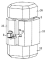
次に、図2を参照して、本実施の形態1の給湯装置の特徴的構成について説明する。図2は、貯湯タンク3の断熱構造を示す図である。図2に示すとおり、円筒状の貯湯タンク3は、その外郭の上部、中央右部、中央左部、および下部の4つに分割された断熱材30,31,32,33で覆われている。断熱材30,31,32,33は、貯湯タンク3を保温断熱するための断熱材であって、例えば発泡スチロール等の発泡性の成型断熱材によって形成されている。貯湯タンク3の中央部(円筒側面部)を覆う断熱材31,32には、それらが互いに当接する面を跨いで凹状の断熱材切欠き部35(嵌合部)が設けられている。本実施の形態1の給湯装置では、ふろ循環ポンプ8を後述する挿入用断熱材34に固定し、当該断熱材切欠き部35に嵌挿する構造に特徴を有している。以下、これらの構造について更に詳細に説明する。   Next, a characteristic configuration of the hot water supply apparatus according to the first embodiment will be described with reference to FIG. FIG. 2 is a view showing a heat insulating structure of the hot water storage tank 3. As shown in FIG. 2, the cylindrical hot water storage tank 3 is covered with heat insulating materials 30, 31, 32, and 33 divided into an upper part, a central right part, a central left part, and a lower part of the outer shell. . The heat insulating materials 30, 31, 32, and 33 are heat insulating materials for heat insulation of the hot water storage tank 3, and are formed of, for example, a foamed molded heat insulating material such as expanded polystyrene. The heat insulating materials 31 and 32 covering the central portion (cylindrical side surface portion) of the hot water storage tank 3 are provided with a concave heat insulating material notch portion 35 (fitting portion) across the surfaces where they abut each other. The hot water supply apparatus according to the first embodiment is characterized by a structure in which the bath circulation pump 8 is fixed to a heat insulating material 34 for insertion, which will be described later, and is inserted into the heat insulating material notch 35. Hereinafter, these structures will be described in more detail.

図3は、挿入用断熱材34の構造を示す図である。尚、図3(a)は挿入用断熱材34の斜視図を、図3(b)は挿入用断熱材34を図3(a)中の矢印Aの方向から見た正面図を、それぞれ示している。これらの図に示すとおり、挿入用断熱材34には、後述するポンプ支持架台54(ポンプ支持部材)を収めるための切削部50(スリット溝)、断熱材31,32の当接面の離反を抑制するためのカギ部51(突起部)、および後述するふろ循環ポンプ排水栓55を囲むための排水栓囲み部52が、それぞれ形成されている。   FIG. 3 is a view showing the structure of the heat insulating material 34 for insertion. 3A is a perspective view of the heat insulating material 34 for insertion, and FIG. 3B is a front view of the heat insulating material 34 for insertion viewed from the direction of arrow A in FIG. 3A. ing. As shown in these drawings, the heat insulating material 34 for insertion includes a cutting portion 50 (slit groove) for accommodating a pump support frame 54 (pump support member) described later, and separation of the contact surfaces of the heat insulating materials 31 and 32. A key part 51 (protrusion part) for suppressing and a drain plug surrounding part 52 for enclosing a bath circulation pump drain plug 55 described later are formed.

図4は、断熱材切欠き部35と挿入用断熱材34との嵌挿構造を説明するための図である。この図に示すとおり、カギ部51は、断熱材31,32に形成された断熱材切欠き部35への挿入方向に向かって延びる突起であって、その先端の外側の角が面取りされた形状になっている。一方、断熱材切欠き部35は、矩形形状の凹部として形成され、その外形が挿入用断熱材34の外形と嵌合する大きさに設定されている。また、凹部の底面351の長手方向の端部には、カギ部51が挿入されるための更なる凹部352がそれぞれ形成されている。このような構造によれば、断熱材切欠き部35に挿入用断熱材34を嵌挿することにより、挿入用断熱材34のカギ部51が断熱材31,32の各凹部352に架かるので、断熱材31,32の当接面が離反する事態を有効に抑止することができる。   FIG. 4 is a view for explaining a fitting structure between the heat insulating material notch 35 and the heat insulating material 34 for insertion. As shown in this figure, the key part 51 is a protrusion that extends in the direction of insertion into the heat insulating material notch 35 formed in the heat insulating materials 31 and 32, and the outer corner of the tip is chamfered. It has become. On the other hand, the heat insulating material notch 35 is formed as a rectangular recess, and its outer shape is set to a size that fits the outer shape of the heat insulating material 34 for insertion. Further, further concave portions 352 for inserting the key portions 51 are respectively formed at the longitudinal ends of the bottom surface 351 of the concave portions. According to such a structure, by inserting the heat insulating material 34 for insertion into the heat insulating material notch 35, the key portion 51 of the heat insulating material 34 for insertion hangs on the respective recesses 352 of the heat insulating materials 31, 32. The situation where the contact surfaces of the heat insulating materials 31 and 32 are separated can be effectively suppressed.

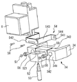
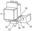
図5は、挿入用断熱材34にふろ循環ポンプ8を固定するための構造およびその部品構成を説明するための分解斜視図である。また、図6は、挿入用断熱材34にふろ循環ポンプ8を固定した状態を示す斜視図であり、図7は、挿入用断熱材34にふろ循環ポンプ8を固定した状態を示す上面図である。これらの図に示すとおり、ふろ循環ポンプ8は、ポンプ支持架台54を用いて挿入用断熱材34に固定される。ポンプ支持架台54は、挿入用断熱材34に固定される側の固定部541と、ふろ循環ポンプ8が設置される側のポンプ設置部542と、該固定部541とポンプ設置部542とを架け渡す架け渡し部543とを有している。   FIG. 5 is an exploded perspective view for explaining the structure for fixing the bath circulation pump 8 to the heat insulating material 34 for insertion and its component configuration. 6 is a perspective view showing a state where the bath circulation pump 8 is fixed to the heat insulating material 34 for insertion, and FIG. 7 is a top view showing a state where the bath circulation pump 8 is fixed to the heat insulating material 34 for insertion. is there. As shown in these drawings, the bath circulation pump 8 is fixed to the insertion heat insulating material 34 by using a pump support frame 54. The pump support base 54 includes a fixing portion 541 on the side fixed to the heat insulating material 34 for insertion, a pump installation portion 542 on the side where the bath circulation pump 8 is installed, and the fixing portion 541 and the pump installation portion 542. And a bridging portion 543 for passing.

図5乃至図7に示すとおり、ふろ循環ポンプ8は、ポンプ締結ネジ58によってポンプ支持架台54のポンプ設置部542に締結される。また、ポンプ支持架台54は、架け渡し部543が切削部50の隙間に挿入され、ポンプ設置部543が挿入用断熱材34の表面341側に突出し、且つ、固定部541が挿入用断熱材34の裏面343へ密着された配置で挿入用断熱材34に固定される。挿入用断熱材34およびポンプ支持架台54には、表面341側から固定部541まで貫通するように孔342,544がそれぞれ設けられている。ここでは、具体的には、これらの孔342および孔544に防振ゴム(ウェルナット)56及び防振ゴム締結ネジ57を挿入することで、ポンプ支持架台54と挿入用断熱材34とが締結される。   As shown in FIGS. 5 to 7, the bath circulation pump 8 is fastened to the pump installation part 542 of the pump support frame 54 by the pump fastening screw 58. Further, in the pump support frame 54, the bridging portion 543 is inserted into the gap of the cutting portion 50, the pump installation portion 543 protrudes toward the surface 341 side of the insertion heat insulating material 34, and the fixing portion 541 is inserted. It is fixed to the heat insulating material 34 for insertion in the arrangement | positioning closely_contact | adhered to the back surface 343. The insertion heat insulating material 34 and the pump support frame 54 are provided with holes 342 and 544 so as to penetrate from the surface 341 side to the fixing portion 541. Here, specifically, the pump support frame 54 and the heat insulating material 34 for insertion are fastened by inserting the vibration-proof rubber (well nut) 56 and the vibration-proof rubber fastening screw 57 into the holes 342 and 544. Is done.

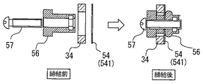
図8は、ポンプ支持架台54と挿入用断熱材34との締結方法について説明するための図である。この図に示すとおり、挿入用断熱材34とポンプ支持架台54の固定部541を重ねた状態で防振ゴム56を挿入し、防振ゴム締結ネジ57を捻じ込むと、該防振ゴム56の中間部が変形して両者が締結される。このような締結構造によれば、振動の発生源であるふろ循環ポンプ8に接続されているポンプ支持架台54に防振効果が薄い防振ゴム締結ネジ57が直接触れず、防振効果がある挿入用断熱材34と防振ゴム56のみが触れる構成となり、振動が有効に抑制される。尚、締結の際には、防振ゴム56と防振ゴム締結ネジ57の間にワッシャーを入れ、取り付け面の応力を緩和する構成としてもよい。   FIG. 8 is a view for explaining a fastening method between the pump support base 54 and the heat insulating material 34 for insertion. As shown in this figure, when the anti-vibration rubber 56 is inserted in a state where the insertion heat insulating material 34 and the fixing portion 541 of the pump support base 54 are overlapped, and the anti-vibration rubber fastening screw 57 is screwed in, the anti-vibration rubber 56 The intermediate portion is deformed and both are fastened. According to such a fastening structure, the anti-vibration rubber fastening screw 57, which has a low anti-vibration effect, does not directly touch the pump support base 54 connected to the bath circulation pump 8 that is the source of vibration, and thus has an anti-vibration effect. Only the heat insulating material 34 for insertion and the vibration isolating rubber 56 are in contact with each other, and vibration is effectively suppressed. In addition, it is good also as a structure which puts a washer between the anti-vibration rubber 56 and the anti-vibration rubber fastening screw 57 at the time of fastening, and relieve | moderates the stress of an attachment surface.

また、切削部50の隙間は、ふろ循環ポンプ8が駆動されて振動した場合でも、架け渡し部543が当該切削部50に接触しないスリット幅に設定されている。これにより、ふろ循環ポンプ8の振動が架け渡し部543を介して切削部50に直接伝わる事態を有効に抑止することができる。   In addition, the gap of the cutting part 50 is set to a slit width in which the bridging part 543 does not contact the cutting part 50 even when the bath circulation pump 8 is driven to vibrate. As a result, it is possible to effectively suppress the situation in which the vibration of the bath circulation pump 8 is directly transmitted to the cutting unit 50 via the bridging unit 543.

更に、図5乃至図7に示すとおり、挿入用断熱材34の表面341側の中央部には、ふろ循環ポンプ排水栓53が挿入される貫通孔521を有する排水栓囲み部52が形成されている。このような構成によれば、万一循環ポンプ排水栓53から湯水が漏れた場合であっても、これらの湯水が該給湯機内に飛散する事態を有効に抑止することができる。   Further, as shown in FIGS. 5 to 7, a drain plug surrounding portion 52 having a through hole 521 into which the bath circulation pump drain plug 53 is inserted is formed in the central portion on the surface 341 side of the heat insulating material 34 for insertion. Yes. According to such a configuration, even if hot water leaks from the circulation pump drain plug 53, it is possible to effectively suppress the situation where these hot water is scattered in the water heater.

以上説明したとおり、断熱材31,32の断熱材切欠き部35にふろ循環ポンプ8が固定された挿入用断熱材34を嵌挿する構造とすることで、部品数が少なく構成が単純な低コストのふろ循環ポンプ8の固定構造を得ることができる。また、挿入用断熱材34とポンプ支持架台54とを防振ゴム56及び防振ゴム締結ネジ57で締結することで、振動の発生源であるふろ循環ポンプ8から給湯機内部への振動影響が極力減少するので、振動音を有効に減少させることが可能となる。また挿入用断熱材34のカギ部51を断熱材切欠き部35の凹部352に挿入させることで、断熱材31、32の当接面の離反を有効に抑制することができる。更に挿入用断熱材34に排水栓囲み部52を設けることで、万一ふろ循環ポンプ8と循環ポンプ排水栓53との接続箇所から水漏れが起こったとしても、水滴が周辺の機能部品に掛かる被害を防止することができる。   As described above, by adopting a structure in which the heat insulating material 34 for insertion in which the bath circulation pump 8 is fixed is inserted into the heat insulating material notch portions 35 of the heat insulating materials 31 and 32, the number of parts is small and the structure is simple. A costly fixed structure of the circulation pump 8 can be obtained. In addition, by fastening the heat insulating material for insertion 34 and the pump support base 54 with the vibration isolating rubber 56 and the vibration isolating rubber fastening screw 57, the influence of vibration from the bath circulation pump 8 which is the source of vibration to the inside of the water heater is reduced. Since it decreases as much as possible, it is possible to effectively reduce the vibration noise. Further, by inserting the key 51 of the heat insulating material 34 for insertion into the recess 352 of the heat insulating material notch 35, separation of the contact surfaces of the heat insulating materials 31 and 32 can be effectively suppressed. Further, by providing the drain plug enclosure 52 in the heat insulating material 34 for insertion, even if water leaks from the connection point between the circulation pump 8 and the circulation pump drain plug 53, water droplets are applied to the surrounding functional parts. Damage can be prevented.

ところで、上述した実施の形態1の貯湯式給湯機においては、挿入用断熱材34にふろ循環ポンプ8を固定することとしているが、振動の発生源となる機器であれば、他のポンプ等を固定することとしてもよい。また、上述した実施の形態1の貯湯式給湯機においては、挿入用断熱材34とポンプ支持架台54とを防振ゴム56及び防振ゴム締結ネジ57で締結することとしているが、ポンプ支持架台54に直接金属部品が接触しないように締結することができるのであれば、例えば防振ゴム(ウェルナット)56に代えてゴム製のワッシャー等を用いることとしてもよい。   By the way, in the hot water storage type hot water heater of the first embodiment described above, the bath circulation pump 8 is fixed to the heat insulating material 34 for insertion. It may be fixed. Further, in the hot water storage type water heater of the first embodiment described above, the heat insulating material 34 for insertion and the pump support frame 54 are fastened by the vibration isolation rubber 56 and the vibration isolation rubber fastening screw 57. As long as it can be fastened so that the metal part does not directly contact 54, a rubber washer or the like may be used instead of the anti-vibration rubber (well nut) 56, for example.

また、上述した実施の形態1の貯湯式給湯機においては、挿入用断熱材34のカギ部51を断熱材切欠き部35の凹部352に挿入させることで、断熱材31、32の当接面の離反を抑制することとしているが、カギ部51および凹部352の形状は上述した実施の形態に限定されない。すなわち、カギ部51および凹部352は、当接面の離反方向の力に対して抗力を発生しうる嵌合形状であればよく、例えば、カギ部51が挿入用断熱材34の表面341に沿って外形から突出する方向に設けられていてもよいし、また、挿入用断熱材34側に凹部を設け、断熱材切欠き部35にカギ部を設けることとしてもよい。より好ましくは、離反を抑制するため、挿入用断熱材34を断熱材31、32よりも高強度の材料で構成してもよい。(例えば発泡率を下げて高強度化する等)   Further, in the hot water storage type water heater of the first embodiment described above, the contact surfaces of the heat insulating materials 31 and 32 are inserted by inserting the key portion 51 of the heat insulating material 34 for insertion into the concave portion 352 of the heat insulating material notch portion 35. However, the shapes of the key 51 and the recess 352 are not limited to the above-described embodiments. That is, the key 51 and the recess 352 may have any fitting shape that can generate a resistance against the force in the separation direction of the contact surface. For example, the key 51 along the surface 341 of the insertion heat insulating material 34. It may be provided in a direction protruding from the outer shape, or a recess may be provided on the insertion heat insulating material 34 side, and a key portion may be provided in the heat insulating material notch 35. More preferably, the insertion heat insulating material 34 may be made of a material having higher strength than the heat insulating materials 31 and 32 in order to suppress separation. (For example, lowering the foaming rate to increase strength)

また、上述した実施の形態1の貯湯式給湯機においては、挿入用断熱材34の表面341側の中央部に貫通孔521を有する排水栓囲み部52を形成することとしているが、ふろ循環ポンプ8と循環ポンプ排水栓53との接続箇所の周囲を覆うことが可能な形状であれば、その形状は特に限定されない。   Further, in the hot water storage type water heater of the first embodiment described above, the drain plug surrounding portion 52 having the through hole 521 is formed in the central portion on the surface 341 side of the heat insulating material 34 for insertion. The shape is not particularly limited as long as it is a shape that can cover the periphery of the connection portion between the circulator 8 and the circulation pump drain plug 53.

また、上述した実施の形態1の貯湯式給湯機においては、断熱材31,32の当接面を跨いで断熱材切欠き部35を形成することとしているが、断熱材同士が当接する当接面を跨ぐ位置に配置されるのであれば、その配置は特に限定しない。   Moreover, in the hot water storage type water heater of Embodiment 1 described above, the heat insulating material notch 35 is formed across the contact surfaces of the heat insulating materials 31 and 32, but the heat insulating materials contact each other. If it arrange | positions in the position which straddles a surface, the arrangement | positioning will not specifically limit.

3 貯湯タンク
8 ふろ循環ポンプ(ポンプ)
30、31、32、33 断熱材
34 挿入用断熱材
35 断熱材切欠き部(嵌合部)
50 切削部(スリット溝)
51 カギ部(突起部)
52 排水栓囲み部
53 排水栓(排水部)
54 ポンプ支持架台(ポンプ支持部材)
541 固定部
542 ポンプ設置部
56 防振ゴム(ウェルナット)
57 防振ゴム締結ネジ
3 Hot water storage tank 8 Bath circulation pump (pump)
30, 31, 32, 33 Insulating material 34 Insulating material 35 for insertion Insulating material notch (fitting part)
50 Cutting part (slit groove)
51 Key (protrusion)
52 Drainage plug enclosure 53 Drainage plug (drainage)
54 Pump support frame (pump support member)
541 Fixing part 542 Pump installation part 56 Anti-vibration rubber (well nut)
57 Anti-vibration rubber fastening screw

Claims (6)

湯水を貯湯する貯湯タンクと、湯水を送水するポンプと、を備えた貯湯式給湯機であって、
前記貯湯タンクを覆う形状に形成された断熱材と、
前記断熱材に設けられた嵌合部に嵌挿されて固定された挿入用断熱材と、
前記挿入用断熱材に固定されたポンプ支持部材と、を備え、
前記ポンプ支持部材は、前記ポンプが設置されるためのポンプ設置部を有し、前記挿入用断熱材が前記嵌合部に嵌挿された場合に、前記ポンプ設置部が外部に突出する形状に形成されていることを特徴とする貯湯式給湯機。
A hot water storage water heater comprising a hot water storage tank for storing hot water and a pump for supplying hot water,
A heat insulating material formed in a shape covering the hot water storage tank;
A heat insulating material for insertion, which is fixed by being inserted into a fitting portion provided in the heat insulating material;
A pump support member fixed to the heat insulating material for insertion,
The pump support member has a pump installation portion for installing the pump, and when the heat insulating material for insertion is inserted into the fitting portion, the pump installation portion protrudes to the outside. A hot water storage type water heater characterized by being formed.
前記ポンプ支持部材は、防振部材を介して前記挿入用断熱材に固定したことを特徴とする請求項1記載の貯湯式給湯機。   The hot water storage type hot water heater according to claim 1, wherein the pump support member is fixed to the heat insulating material for insertion through a vibration isolating member. 前記断熱材は、少なくとも2つの断熱材を当接させて構成され、前記嵌合部は、前記2つの断熱材の当接面を跨いで形成され、
前記挿入用断熱材および前記嵌合部は、前記当接面の離反に対する抗力を発する嵌合構造を有することを特徴とする請求項1または2に記載の貯湯式給湯機。
The heat insulating material is configured by contacting at least two heat insulating materials, and the fitting portion is formed across the contact surface of the two heat insulating materials,
The hot water storage type hot water supply apparatus according to claim 1 or 2, wherein the heat insulating material for insertion and the fitting portion have a fitting structure that generates a resistance against separation of the contact surface.
前記挿入用断熱材は、前記ポンプ支持部材が外部へと突出するための溝を更に備え、
前記溝は、前記ポンプを作動した場合に前記ポンプ支持部材と当該溝とが接触しない溝幅に設定されていることを特徴とする請求項1乃至3の何れか1項記載の貯湯式給湯機。
The heat insulating material for insertion further includes a groove for the pump support member to protrude to the outside,
The hot water storage type hot water heater according to any one of claims 1 to 3, wherein the groove is set to have a groove width that does not contact the pump support member and the groove when the pump is operated. .
前記挿入用断熱材は、前記固定部に設置された前記ポンプの排水部を囲う囲み部を更に備えることを特徴とする請求項1乃至6の何れか1項記載の貯湯式給湯機。   The hot water storage type hot water heater according to any one of claims 1 to 6, wherein the heat insulating material for insertion further includes a surrounding portion surrounding a drainage portion of the pump installed in the fixed portion. 前記挿入用断熱材は前記断熱材よりも機械的強度の高い材料で構成したことを特徴とする請求項1乃至5の何れか1項記載の貯湯式給湯機。   The hot water storage type hot water heater according to any one of claims 1 to 5, wherein the heat insulating material for insertion is made of a material having higher mechanical strength than the heat insulating material.
JP2011062637A 2011-03-22 2011-03-22 Storage type water heater Withdrawn JP2012197983A (en)

Priority Applications (1)

Application Number Priority Date Filing Date Title
JP2011062637A JP2012197983A (en) 2011-03-22 2011-03-22 Storage type water heater

Applications Claiming Priority (1)

Application Number Priority Date Filing Date Title
JP2011062637A JP2012197983A (en) 2011-03-22 2011-03-22 Storage type water heater

Publications (1)

Publication Number Publication Date
JP2012197983A true JP2012197983A (en) 2012-10-18

Family

ID=47180386

Family Applications (1)

Application Number Title Priority Date Filing Date
JP2011062637A Withdrawn JP2012197983A (en) 2011-03-22 2011-03-22 Storage type water heater

Country Status (1)

Country Link
JP (1) JP2012197983A (en)

Cited By (2)

* Cited by examiner, † Cited by third party
Publication number Priority date Publication date Assignee Title
JP2016217568A (en) * 2015-05-15 2016-12-22 東芝キヤリア株式会社 Hot water storage type water heater and screw
WO2020217270A1 (en) * 2019-04-22 2020-10-29 三菱電機株式会社 Polyurethane foam insulation material and storage water heater

Cited By (4)

* Cited by examiner, † Cited by third party
Publication number Priority date Publication date Assignee Title
JP2016217568A (en) * 2015-05-15 2016-12-22 東芝キヤリア株式会社 Hot water storage type water heater and screw
WO2020217270A1 (en) * 2019-04-22 2020-10-29 三菱電機株式会社 Polyurethane foam insulation material and storage water heater
JPWO2020217270A1 (en) * 2019-04-22 2021-10-28 三菱電機株式会社 Polyurethane foam insulation and hot water storage type water heater
JP7156510B2 (en) 2019-04-22 2022-10-19 三菱電機株式会社 Polyurethane foam insulation and storage water heater

Similar Documents

Publication Publication Date Title
JP4211786B2 (en) Hot water storage water heater
JP6014720B2 (en) TANK UNIT, ITS MANUFACTURING METHOD, AND HOT WATER SUPPLY SYSTEM
JP5958040B2 (en) Hot water storage water heater
JP2012197983A (en) Storage type water heater
US8893916B2 (en) Hot water storage tank unit
WO2015019632A1 (en) Tank unit, method for manufacturing same, and hot-water supply system
WO2013008481A1 (en) Panel heating device
JP6447191B2 (en) Hot water storage water heater
JP2012137213A (en) Heat pump type heat source machine
JP2009133586A (en) Water heater
JP2012220066A (en) Hot water storage type water heater
JP6090133B2 (en) Hot water storage water heater
JP6237455B2 (en) Hot water storage water heater
JP2014001904A (en) Hot-water storage type hot-water dispenser
JP2019184198A (en) Hot water storage type water heater
JP5592758B2 (en) Maintenance method of temperature detection means, tank and water heater provided with tank
JP2004286288A (en) Passage branching device
JP2012149779A (en) Floor heating unit
JP3798315B2 (en) Floor heating system
JP5664620B2 (en) Thermal insulation structure and hot water storage unit
AU2020289776B2 (en) Kettle
JP5968495B2 (en) Hot water storage tank unit
JP2013162923A (en) Mirror unit
JP6954258B2 (en) Hot water storage type water heater
JP6617484B2 (en) Human body local cleaning equipment

Legal Events

Date Code Title Description
A300 Withdrawal of application because of no request for examination

Free format text: JAPANESE INTERMEDIATE CODE: A300

Effective date: 20140603