JP2012197793A - Fuel tank - Google Patents
Fuel tank Download PDFInfo
- Publication number
- JP2012197793A JP2012197793A JP2012123144A JP2012123144A JP2012197793A JP 2012197793 A JP2012197793 A JP 2012197793A JP 2012123144 A JP2012123144 A JP 2012123144A JP 2012123144 A JP2012123144 A JP 2012123144A JP 2012197793 A JP2012197793 A JP 2012197793A
- Authority
- JP
- Japan
- Prior art keywords
- tank
- canister
- fuel
- liquid
- partially
- Prior art date
- Legal status (The legal status is an assumption and is not a legal conclusion. Google has not performed a legal analysis and makes no representation as to the accuracy of the status listed.)
- Pending
Links
Images

Classifications
-
- F—MECHANICAL ENGINEERING; LIGHTING; HEATING; WEAPONS; BLASTING
- F02—COMBUSTION ENGINES; HOT-GAS OR COMBUSTION-PRODUCT ENGINE PLANTS
- F02M—SUPPLYING COMBUSTION ENGINES IN GENERAL WITH COMBUSTIBLE MIXTURES OR CONSTITUENTS THEREOF
- F02M37/00—Apparatus or systems for feeding liquid fuel from storage containers to carburettors or fuel-injection apparatus; Arrangements for purifying liquid fuel specially adapted for, or arranged on, internal-combustion engines
- F02M37/0076—Details of the fuel feeding system related to the fuel tank
- F02M37/0082—Devices inside the fuel tank other than fuel pumps or filters
-
- B—PERFORMING OPERATIONS; TRANSPORTING
- B60—VEHICLES IN GENERAL
- B60K—ARRANGEMENT OR MOUNTING OF PROPULSION UNITS OR OF TRANSMISSIONS IN VEHICLES; ARRANGEMENT OR MOUNTING OF PLURAL DIVERSE PRIME-MOVERS IN VEHICLES; AUXILIARY DRIVES FOR VEHICLES; INSTRUMENTATION OR DASHBOARDS FOR VEHICLES; ARRANGEMENTS IN CONNECTION WITH COOLING, AIR INTAKE, GAS EXHAUST OR FUEL SUPPLY OF PROPULSION UNITS IN VEHICLES
- B60K15/00—Arrangement in connection with fuel supply of combustion engines or other fuel consuming energy converters, e.g. fuel cells; Mounting or construction of fuel tanks
- B60K15/03—Fuel tanks
- B60K15/035—Fuel tanks characterised by venting means
- B60K15/03504—Fuel tanks characterised by venting means adapted to avoid loss of fuel or fuel vapour, e.g. with vapour recovery systems
-
- F—MECHANICAL ENGINEERING; LIGHTING; HEATING; WEAPONS; BLASTING
- F02—COMBUSTION ENGINES; HOT-GAS OR COMBUSTION-PRODUCT ENGINE PLANTS
- F02M—SUPPLYING COMBUSTION ENGINES IN GENERAL WITH COMBUSTIBLE MIXTURES OR CONSTITUENTS THEREOF
- F02M25/00—Engine-pertinent apparatus for adding non-fuel substances or small quantities of secondary fuel to combustion-air, main fuel or fuel-air mixture
- F02M25/08—Engine-pertinent apparatus for adding non-fuel substances or small quantities of secondary fuel to combustion-air, main fuel or fuel-air mixture adding fuel vapours drawn from engine fuel reservoir
- F02M25/0854—Details of the absorption canister
-
- F—MECHANICAL ENGINEERING; LIGHTING; HEATING; WEAPONS; BLASTING
- F02—COMBUSTION ENGINES; HOT-GAS OR COMBUSTION-PRODUCT ENGINE PLANTS
- F02M—SUPPLYING COMBUSTION ENGINES IN GENERAL WITH COMBUSTIBLE MIXTURES OR CONSTITUENTS THEREOF
- F02M37/00—Apparatus or systems for feeding liquid fuel from storage containers to carburettors or fuel-injection apparatus; Arrangements for purifying liquid fuel specially adapted for, or arranged on, internal-combustion engines
- F02M37/04—Feeding by means of driven pumps
- F02M37/08—Feeding by means of driven pumps electrically driven
- F02M37/10—Feeding by means of driven pumps electrically driven submerged in fuel, e.g. in reservoir
-
- B—PERFORMING OPERATIONS; TRANSPORTING
- B60—VEHICLES IN GENERAL
- B60K—ARRANGEMENT OR MOUNTING OF PROPULSION UNITS OR OF TRANSMISSIONS IN VEHICLES; ARRANGEMENT OR MOUNTING OF PLURAL DIVERSE PRIME-MOVERS IN VEHICLES; AUXILIARY DRIVES FOR VEHICLES; INSTRUMENTATION OR DASHBOARDS FOR VEHICLES; ARRANGEMENTS IN CONNECTION WITH COOLING, AIR INTAKE, GAS EXHAUST OR FUEL SUPPLY OF PROPULSION UNITS IN VEHICLES
- B60K15/00—Arrangement in connection with fuel supply of combustion engines or other fuel consuming energy converters, e.g. fuel cells; Mounting or construction of fuel tanks
- B60K15/03—Fuel tanks
- B60K15/035—Fuel tanks characterised by venting means
- B60K2015/03542—Mounting of the venting means
- B60K2015/03557—Mounting of the venting means comprising elements of the venting device integrated in the fuel tank, e.g. vapor recovery means
-
- Y—GENERAL TAGGING OF NEW TECHNOLOGICAL DEVELOPMENTS; GENERAL TAGGING OF CROSS-SECTIONAL TECHNOLOGIES SPANNING OVER SEVERAL SECTIONS OF THE IPC; TECHNICAL SUBJECTS COVERED BY FORMER USPC CROSS-REFERENCE ART COLLECTIONS [XRACs] AND DIGESTS
- Y10—TECHNICAL SUBJECTS COVERED BY FORMER USPC
- Y10T—TECHNICAL SUBJECTS COVERED BY FORMER US CLASSIFICATION
- Y10T137/00—Fluid handling
- Y10T137/0753—Control by change of position or inertia of system
- Y10T137/0874—Vent opening or closing on tipping container
-
- Y—GENERAL TAGGING OF NEW TECHNOLOGICAL DEVELOPMENTS; GENERAL TAGGING OF CROSS-SECTIONAL TECHNOLOGIES SPANNING OVER SEVERAL SECTIONS OF THE IPC; TECHNICAL SUBJECTS COVERED BY FORMER USPC CROSS-REFERENCE ART COLLECTIONS [XRACs] AND DIGESTS
- Y10—TECHNICAL SUBJECTS COVERED BY FORMER USPC
- Y10T—TECHNICAL SUBJECTS COVERED BY FORMER US CLASSIFICATION
- Y10T137/00—Fluid handling
- Y10T137/2931—Diverse fluid containing pressure systems
- Y10T137/3003—Fluid separating traps or vents
- Y10T137/3084—Discriminating outlet for gas
- Y10T137/309—Fluid sensing valve
- Y10T137/3099—Float responsive
-
- Y—GENERAL TAGGING OF NEW TECHNOLOGICAL DEVELOPMENTS; GENERAL TAGGING OF CROSS-SECTIONAL TECHNOLOGIES SPANNING OVER SEVERAL SECTIONS OF THE IPC; TECHNICAL SUBJECTS COVERED BY FORMER USPC CROSS-REFERENCE ART COLLECTIONS [XRACs] AND DIGESTS
- Y10—TECHNICAL SUBJECTS COVERED BY FORMER USPC
- Y10T—TECHNICAL SUBJECTS COVERED BY FORMER US CLASSIFICATION
- Y10T137/00—Fluid handling
- Y10T137/8593—Systems
- Y10T137/86292—System with plural openings, one a gas vent or access opening
- Y10T137/86324—Tank with gas vent and inlet or outlet
Abstract
Description
本発明は、燃料タンクに関する。 The present invention relates to a fuel tank.
液体または気体燃料用の現在のタンクは、引火性が高くかつ時として毒性をも有する燃料を収容することから、多くの安全規格に適合する必要がある。欠陥のあるシーリングによる燃料漏洩および蒸発による燃料損失ついて、特に自動車用の場合には非常に厳格な規則が設けられている。実際のタンク自体に加え、例えば導管、種々の連結具、ポンプ、フィルタ、蒸気除去キャニスタ(缶)、弁および安全装置等のタンクに付随する非常に多くのアクセサリも燃料を収容する。これらのアクセサリも、しばしば、あらゆる種類の燃料漏洩に、重要な役割を演じている。これらのアクセサリは、時々、これらが関連するタンクと協働して、これらを収納する全システムからの殆どの燃料損失にも応答する。 Current tanks for liquid or gaseous fuels must meet many safety standards because they contain fuels that are highly flammable and sometimes toxic. There are very strict rules for fuel leakage due to defective sealing and fuel loss due to evaporation, especially for automobiles. In addition to the actual tank itself, numerous accessories associated with the tank, such as conduits, various couplings, pumps, filters, vapor removal canisters, valves and safety devices, also contain fuel. These accessories also often play an important role in all types of fuel leaks. These accessories sometimes also cooperate with the tanks with which they are associated to respond to most fuel losses from the entire system that houses them.
従って、タンク自体により引き起こされる漏洩の低減と並行して、これらの各アクセサリおよびこれらを相互連結する装置により直接引き起こされる漏洩をも最小にする研究がなされている。 Accordingly, in parallel with the reduction of leakage caused by the tank itself, research has been done to minimize leakage caused directly by each of these accessories and the devices that interconnect them.
特許文献1には、燃料蒸気を収容するキャニスタであって、タンクの内部に配置されかつタンクが反転した場合でもタンクから液体が流出することを防止する安全弁を備えているキャニスタが開示されている。この構成は、タンクとキャニスタとを連結する導管を省略すること、および給油蒸気回収装置と前記キャニスタとを連結する導管を短縮することを可能にする。
しかしながら、この従来技術によれば、キャニスタはOP装置には関連付けられておらず、このOP装置とキャニスタとの連結による蒸気損失の危険性は無視できるほど小さくはない。 However, according to this prior art, the canister is not associated with the OP device, and the risk of steam loss due to the connection between the OP device and the canister is not negligibly small.
また、タンク内に組み込まれるこのキャニスタの取付けの複雑性および独立したOP装置の複雑性は依然として高度である。タンクの存在を含む燃料システム(ORVR、OBD等)でしばしば遭遇する他の機能を満たす他の装置についても同じことがいえる。 Also, the complexity of installing this canister built into the tank and the complexity of an independent OP device are still high. The same is true for other devices that fulfill other functions often encountered in fuel systems (ORVR, OBD, etc.) including the presence of a tank.
また、上記特許文献1に開示されたキャニスタでは、キャニスタ内部の傾斜チューブの下端部に位置するオリフィスの位置により定められるレベルを超えないようにしかつ液体燃料をタンクに戻す必要性から、タンク内に許容される最高燃料レベルは比較的低くなっており、さもなくば、蒸気からの液体燃料の分離が妨げられてしまうであろう。最後に、この形式のキャニスタは、タンクが過大角度に傾斜された場合で、反転時にタンクを閉じる弁が、該弁の重い部分を下降位置に維持する重力の合力が依然として存在することによって開状態に維持されるときには、弁自体が燃料中に浸漬された状態になろうとする。この状況は、タンクからの液体燃料の漏洩、およびキャニスタを満たす組成物の燃料/気体保持活性(fuel−gas−retaining activity)の喪失を引き起こす。
Further, in the canister disclosed in
本発明の目的は、外部大気への液体および気体燃料の漏洩をなくすか極く僅かに制限すると同時に、最新の燃料システムにより一般に達成される安全機能を満たしかつタンク取付けの複雑性を極めて簡単化できるタンクを提供することにより、既知のタンクの欠点を解消することにある。 The object of the present invention is to eliminate or very limited the leakage of liquid and gaseous fuels to the outside atmosphere, while at the same time meeting the safety functions commonly achieved by modern fuel systems and greatly simplifying the complexity of tank installation It is to eliminate the disadvantages of the known tanks by providing a tank that can be used.
上記目的を達成するため、本発明は、燃料蒸気を保持できる組成物を収容するキャニスタを有し、該キャニスタが、タンクが過充填されることを防止する過充填防止(overfill prevention:OP)装置に関連しておりかつ少なくとも一部がタンク内に配置されるように構成された燃料タンクを提供する。 To achieve the above object, the present invention has a canister containing a composition capable of holding fuel vapor, and the canister prevents an overfill prevention (OP) device from preventing the tank from being overfilled. And a fuel tank configured to be at least partially disposed within the tank.
「タンク」とは、一般に外部からシールされた種々の形状をもつ閉鎖チャンバであって、チャンバの壁を通って延びる種々の内部アクセサリが設けられた閉鎖チャンバを意味するものと理解すべきである。 "Tank" should be understood to mean a closed chamber of various shapes, generally sealed from the outside, provided with various internal accessories extending through the walls of the chamber. .
本発明によるタンクは、燃料および一般的使用条件と相容性のある任意の組成物または材料で作ることができる。タンクは、例えば、少なくとも1つの金属またはプラスチックを組成物として含む材料で作ることができる。少なくとも1つのプラスチックで作られたタンクが好ましい。 The tank according to the present invention can be made of any composition or material that is compatible with the fuel and general use conditions. The tank can be made, for example, of a material comprising at least one metal or plastic as a composition. A tank made of at least one plastic is preferred.
「プラスチック」とは、周囲の大気条件下で固体状態にある任意の合成ポリマー材料を意味するものと理解すべきである。本発明に従ってプラスチックで作られるタンクは、単層タンクまたは多層タンクの形態に構成できる。単層または多層の高密度ポリエチレンからなるタンクが特に好ましい。 “Plastic” should be understood as meaning any synthetic polymeric material that is in a solid state under ambient atmospheric conditions. Tanks made of plastic according to the present invention can be configured in the form of a single layer tank or a multilayer tank. A tank made of single-layer or multilayer high-density polyethylene is particularly preferred.
「燃料」とは、酸化剤、一般的には空気中の酸素の存在下で燃焼できるあらゆる化学的組成物であって、燃焼エンジンに使用できる化学的組成物を意味するものと理解すべきである。燃料は、大気温度で、固体、液体または気体の3つの状態のうちのいずれか1つの状態にある。一般に、車両用には、通常温度および大気圧またはこれより高い温度または圧力で液体または気体である燃料が好ましい。石油およびディーゼル油等の液体燃料が特に好ましい。 “Fuel” is to be understood as meaning any chemical composition that can be combusted in the presence of an oxidant, typically oxygen in the air, that can be used in a combustion engine. is there. The fuel is in any one of three states: solid, liquid or gas at ambient temperature. In general, for vehicles, fuels that are liquid or gaseous at normal temperature and atmospheric pressure or higher are preferred. Liquid fuels such as petroleum and diesel oil are particularly preferred.
本発明によるタンク内に収容される燃料は、空気または酸素等の酸化剤を用いる任意の燃焼装置、例えば中央加熱ボイラまたは燃焼エンジンで燃焼されることを意図したものである。通常、燃料は車両の燃焼エンジンに供給される。「燃焼エンジン」とは、燃料中に含まれる化学的エネルギを機械的エネルギに変換するあらゆるエンジンを意味するものと理解すべきである。この種のエンジンには、液体燃料(例えば、石油、重油、アルコール等)または気体燃料(例えば石油ガス、天然ガス、希薄ガス、水素、メタン等)を使用するピストンまたはロータリ形の任意の形式の内燃機関がある。拡大解釈するならば、「燃焼エンジン」は、燃料が少なくとも1つの炭化水素および/またはアルコールを含有するときに、少なくとも1つの燃料電池で駆動される1つ以上の電気モータをもカバーすることを意図している。 The fuel contained in the tank according to the invention is intended to be combusted in any combustion device using an oxidant such as air or oxygen, for example a central heating boiler or combustion engine. Usually, fuel is supplied to the vehicle's combustion engine. “Combustion engine” should be understood as meaning any engine that converts chemical energy contained in fuel into mechanical energy. For this type of engine, any type of piston or rotary type that uses liquid fuel (eg, petroleum, heavy oil, alcohol, etc.) or gaseous fuel (eg, petroleum gas, natural gas, lean gas, hydrogen, methane, etc.) There is an internal combustion engine. By extension, “combustion engine” means that it also covers one or more electric motors driven by at least one fuel cell when the fuel contains at least one hydrocarbon and / or alcohol. Intended.
本発明によるタンク内に収容されるキャニスタは、気体流の燃料蒸気を保持できる、一般的には固体および粒状の組成物を収容する受容器である。このような組成物の一例として、粒状活性炭があることに留意されたい。キャニスタは、液体燃料および気体燃料との相容性を有し、燃料タンク内で遭遇し易い変化する温度条件および圧力条件下で長期接触することを意図した任意の材料または組成物で作られる。好ましくは、キャニスタは少なくとも一部がプラスチックで作られる。 A canister housed in a tank according to the present invention is a receptacle containing generally solid and granular compositions capable of holding a gaseous stream of fuel vapor. Note that an example of such a composition is granular activated carbon. The canister is made of any material or composition that is compatible with liquid and gaseous fuels and is intended for long-term contact under changing temperature and pressure conditions that are likely to be encountered in a fuel tank. Preferably, the canister is at least partially made of plastic.
ここでの用語「プラスチック」は上記と同じ意味を有している。熱可塑性プラスチックおよび熱硬化性プラスチックが特に適している。熱可塑性プラスチックにより、所与の優れた結果が得られた。本発明によれば、キャニスタはタンク内に収容される。すなわち、キャニスタは、完全にまたは部分的にタンク内に配置される。好ましくは、キャニスタは完全にタンク内に配置される。 The term “plastic” here has the same meaning as above. Thermoplastics and thermosetting plastics are particularly suitable. The thermoplastics gave given excellent results. According to the present invention, the canister is housed in the tank. That is, the canister is completely or partially disposed in the tank. Preferably, the canister is placed completely in the tank.
キャニスタが完全にタンク内に配置されるときには、キャニスタは任意の既知の固定手段によりタンクに固定される。可能な固定手段として次のもの、すなわち、タンクの一壁と共通の底壁、側壁または頂壁;タンクの壁に溶接される底壁、側壁または頂壁:タンクの壁に固定された壁または内部にボルト止めされたキャニスタの壁からの突出部;タンクの内壁にくりぬかれて溝として形成された1つ以上の案内面内へのキャニスタ壁のクリッピングがあるが、これらに限定されるものではない。 When the canister is completely placed in the tank, the canister is secured to the tank by any known securing means. Possible fixing means are: bottom wall, side wall or top wall in common with one wall of tank; bottom wall, side wall or top wall welded to tank wall: wall fixed to tank wall or Projection from the canister wall bolted inside; clipping of the canister wall into one or more guide surfaces formed into a groove cut into the inner wall of the tank, including but not limited to Absent.
キャニスタがタンク内に部分的に配置される場合には、キャニスタはタンクの壁、例えば頂壁を貫通する。この場合には、浄化すべき蒸気を収容するガス入口導管およびクリーンガス出口導管を支持するカバーにより、シールされた態様で閉じられるのが好ましい。また、カバーは、燃料に対して事実上不透過性を有する少なくとも1つの材料で作るのが好ましい。 If the canister is partially disposed within the tank, the canister penetrates the tank wall, eg, the top wall. In this case, it is preferably closed in a sealed manner by a cover supporting the gas inlet conduit containing the vapor to be purified and the clean gas outlet conduit. The cover is also preferably made of at least one material that is virtually impermeable to fuel.
本発明によれば、キャニスタは、タンクの過充填を防止する過充填防止装置に関連付けられる。 According to the present invention, the canister is associated with an overfill prevention device that prevents overfilling of the tank.
「OP装置」とは、タンクの有効体積を一定にしかつ充填作業中に液体がタンク中で所定レベルを超えることを防止する機能を有する任意の装置を意味するものと理解すべきである。OP装置は、この機能を満たすあらゆる既知の装置から選択できる。液体燃料を受け入れることを意図した容量をもつガス出口導管を重力により遮断する稠密ボールを備えた特別なOP装置により、所与の優れた結果が得られる。OP装置は、燃料蒸気が充填パイプのタンクの外部の端部から放出されるときに特に有効である。 An “OP device” should be understood as meaning any device having the function of keeping the effective volume of the tank constant and preventing liquid from exceeding a predetermined level in the tank during the filling operation. The OP device can be selected from any known device that fulfills this function. The given OP results with a dense ball that closes the gas outlet conduit with the capacity intended to receive liquid fuel by gravity, give a given excellent result. The OP device is particularly effective when fuel vapor is released from the outside end of the tank of the fill pipe.
本発明によるOP装置は、少なくとも一部をタンク内に配置することもできる。「少なくとも一部をタンク内」の表現は、キャニスタに関連して前述したように、タンク内に完全にまたは部分的に配置されることを意味するものである。 The OP device according to the present invention can be at least partially disposed in the tank. The expression “at least partly in the tank” is intended to mean that it is completely or partially arranged in the tank as described above in connection with the canister.
本発明によるタンクに適した他の特別なOP装置として、1対の稠密部分およびばねを有し、この位置が燃料のレベルに従って変化する構成のフロート形OP装置がある。 Another special OP device suitable for the tank according to the invention is a float type OP device with a pair of dense parts and springs, the position of which varies according to the fuel level.
OP装置はキャニスタに関連付けられる。すなわち、OP装置はキャニスタと協働して、周囲の環境に対するタンクの全体的安全性を確保する。OP装置は種々の態様でキャニスタに関連付けられる。OP装置は、キャニスタとは全く別の装置として構成し、両者は、例えば連結導管、導電体、機械的リンク部材等の1つ以上の連結手段により関連付けられるように構成するか、或いは、壁または内部体積等のキャニスタおよび/またはOP装置の本質的要素でキャニスタと共有させるように構成できる。 The OP device is associated with the canister. That is, the OP device cooperates with the canister to ensure the overall safety of the tank relative to the surrounding environment. The OP device is associated with the canister in various ways. The OP device is configured as a completely separate device from the canister, both configured to be associated by one or more connecting means such as connecting conduits, conductors, mechanical link members, etc. The canister and / or the essential elements of the OP device, such as the internal volume, can be configured to be shared with the canister.
OP装置は、少なくとも1つの1つの本質的要素でキャニスタと共有させるのが好ましい。特に好ましくは、OP装置は、少なくとも1つの共通壁でキャニスタと共有させる。 The OP device is preferably shared with the canister by at least one essential element. Particularly preferably, the OP device is shared with the canister by at least one common wall.
「共通壁」とは、キャニスタおよびOP装置により等しく使用される壁を意味するものと理解すべきである。この共通壁は、OP装置の使用前、またはキャニスタの壁とOP装置の壁とを例えば溶接または接着することによりタンク内に組み込んだ後に、組立体から得ることができる。或いは、共通壁は、例えばキャビティおよびOP装置の両方を包囲する複合装置を成形することにより、製造から直接得ることができる。 “Common wall” should be understood to mean a wall that is equally used by canisters and OP devices. This common wall can be obtained from the assembly prior to use of the OP device or after it has been incorporated into the tank, for example by welding or gluing the walls of the canister and the OP device. Alternatively, the common wall can be obtained directly from manufacturing, for example by molding a composite device that surrounds both the cavity and the OP device.
OP装置はまた、キャニスタに関連して前述したのと同じ態様でタンクに固定することもできる。或いは、OP装置は、任意の既知の方法で単にキャニスタに固定することもできる。或いは、OP装置は、タンクおよびキャニスタの両方に固定することもできる。 The OP device can also be secured to the tank in the same manner as described above in connection with the canister. Alternatively, the OP device can simply be secured to the canister in any known manner. Alternatively, the OP device can be fixed to both the tank and the canister.
本発明によるタンクの特定の第1実施形態では、キャニスタはまた、少なくとも一部がタンク内に配置される液体−蒸気分離装置と関連付けられている。 In a first particular embodiment of the tank according to the invention, the canister is also associated with a liquid-vapor separation device which is at least partially arranged in the tank.
「液体−蒸気分離装置」とは、同伴により燃料蒸気を帯同した気体の流れを伴うことがある、液体燃料を保持できる任意の装置を意味するものと理解すべきである。特別には、液体−蒸気分離装置は、タンクを出ることがある、燃料蒸気を含有する気体と一緒に運ばれる液体燃料の小滴を保持できるあらゆる装置をいうものとする。液体−蒸気分離装置は、燃料との相容性を有する任意の材料で作ることができる。熱可塑性プラスチックで作られた液体−蒸気分離装置により優れた結果が得られる。 “Liquid-vapor separation device” should be understood to mean any device capable of holding liquid fuel, which may be accompanied by a gas flow accompanied by fuel vapor by entrainment. In particular, a liquid-vapor separation device shall refer to any device capable of holding droplets of liquid fuel that may be exiting a tank and carried with a gas containing fuel vapor. The liquid-vapor separator can be made of any material that is compatible with the fuel. Excellent results are obtained with liquid-vapor separators made of thermoplastics.
本発明によるタンクのこの特定の実施形態によれば、キャニスタは液体−蒸気分離装置に関連付けられている。 According to this particular embodiment of the tank according to the invention, the canister is associated with a liquid-vapor separator.
ここで使用する用語「関連付ける(associated)」は、OP装置に関連して前述した意味と同じ意味を有する。 As used herein, the term “associated” has the same meaning as described above in connection with the OP device.
この実施形態では、液体−蒸気分離装置は、少なくとも一部がタンク内に配置される。表現「少なくとも一部がタンク内」は、OP装置に関連して前述した同じ表現と同じ意味を有している。 In this embodiment, the liquid-vapor separation device is at least partially disposed in the tank. The expression “at least partly in the tank” has the same meaning as the same expression described above in connection with the OP device.
本発明によるタンクの第2実施形態によれば、キャニスタは、少なくとも一部がタンク内に配置されておりかつタンクが反転した場合にタンクのブリーザを遮断する装置(ROVすなわち反転弁)と関連付けられている。 According to a second embodiment of the tank according to the invention, the canister is associated with a device (ROV or reversing valve) that shuts off the breather of the tank when it is at least partially disposed in the tank and the tank is inverted. ing.
この第2実施形態では、上記他の全ての実施形態におけるように、用語「関連付ける」および「少なくとも一部がタンク内」は、上記実施形態に関連して説明したこれらの用語の意味と同じである。 In this second embodiment, as in all other embodiments above, the terms “associate” and “at least partly in the tank” have the same meaning as those terms described in connection with the above embodiments. is there.
ROV装置は、タンクの設計対象としての通常の位置から遠ざかるタンクの位置の漸次運動又はこれとは対照的な非常に迅速な運動が生じても、タンクからの液体燃料の漏れを回避する機能を備えている。一つの例は、急勾配を登る運動中の車体に固定されたタンク又は変形例として突然の転倒を生じるシステムの一体部分を形成する搭載型タンクの例である。 The ROV device has the function of avoiding liquid fuel leakage from the tank, even if there is a gradual movement of the tank position away from the normal position where the tank is designed or a very rapid movement as opposed to this. I have. One example is an example of a tank that is fixed to a moving body climbing a steep slope or alternatively an onboard tank that forms an integral part of a system that causes a sudden fall.
本発明のタンクの特定の1つの場合は、タンクが液気分離装置及びROV装置を有する上述の2つの実施形態のうち一方又は他方の場合である。好ましくは、タンクは、同時に上述の2つの実施形態と連携しており、換言すると、キャニスタは、それぞれが少なくとも部分的にタンク内に配置された2つの装置の各々と連携している。 One particular case of the tank of the present invention is one or the other of the two embodiments described above where the tank has a liquid-gas separator and a ROV device. Preferably, the tank is simultaneously associated with the two embodiments described above, in other words, the canister is associated with each of the two devices, each at least partially disposed within the tank.
より好ましくは、液気分離装置は、ROV装置の上方に位置している。この構成により、タンクが通常の位置にあるときに開くROV装置の弁を介して、第1の装置内に保持された液体が重力の作用だけでタンクの内部に容易に戻ることができるという利点が得られる。 More preferably, the liquid / gas separation device is located above the ROV device. With this configuration, the liquid held in the first device can be easily returned to the inside of the tank only by the action of gravity through the valve of the ROV device that opens when the tank is in the normal position. Is obtained.
最も好ましくは、タンクのこの特定の場合における液気分離装置は、以下の形態、即ち、漏斗体、螺旋体、ラビリンスを形成する多数の壁から成る組織体のうち少なくとも1つを有している。 Most preferably, the liquid-gas separation device in this particular case of the tank has at least one of the following forms: a funnel body, a spiral body, a tissue body comprising a number of walls forming a labyrinth.
螺旋体及びラビリンスの形状は、ガス流の方向に急激な変化を与えて液体燃料の小滴が凝縮して凝集し、そして保持されるようになる。 The shape of the helix and labyrinth causes a sudden change in the direction of gas flow, causing the liquid fuel droplets to condense, aggregate and be retained.
漏斗体の場合、ガス流から分離された液体燃料は、重力の作用で、漏斗の最も下に位置する箇所に集められる。この場合、この液体燃料をタンクに容易に戻すことができるので有利である。 In the case of a funnel, the liquid fuel separated from the gas stream is collected at the lowest position of the funnel by the action of gravity. This is advantageous because the liquid fuel can be easily returned to the tank.
有利には、上述の形態のうち幾つかをその分離装置内で相互に連携させることができる。 Advantageously, some of the forms described above can be linked together in the separation device.
本発明のタンクの第3の実施形態によれば、キャニスタは、それ自体これ又少なくとも部分的にタンク内に設けられていて、タンクの充填中、燃料蒸気を回収する装置(ORVR又は搭載型燃料補給蒸気回収装置とも呼ばれている)と連携している。 According to a third embodiment of the tank of the present invention, the canister is itself or at least partially provided in the tank and is a device for collecting fuel vapor (ORVR or onboard fuel during filling of the tank). (It is also called a makeup steam recovery device).
かかるORVR装置は、タンクが定期的に充填されている間に放出される燃料蒸気を保持することにより環境を顧慮するという機能を備えている。これは、一般に充填中に放出される蒸気を捕捉するという問題を解決するのに採用された2つの手段のうち一方であり、他方の手段は、タンクとは独立していて、点検整備ステーションの燃料分配ポンプに蒸気抽出装置を装備することから成る。 Such an ORVR device has the function of taking the environment into account by holding the fuel vapor released while the tank is periodically filled. This is one of the two means employed to solve the problem of trapping vapors typically released during filling, the other means being independent of the tank, The fuel distribution pump is equipped with a steam extraction device.
タンク内の燃料及び条件との適合性があり、しかもキャニスタと連携させることができるORVR装置が適している。この装置は、種々の材料、例えば、少なくとも1つのプラスチックを含む材料で作られたものであるのがよい。すべての形式のプラスチック、熱可塑性プラスチック又は熱硬化性プラスチックが適している。熱可塑性プラスチックは、所定の良好な結果をもたらす。 An ORVR device that is compatible with the fuel and conditions in the tank and that can be coordinated with the canister is suitable. The device may be made of a variety of materials, for example, a material comprising at least one plastic. All types of plastics, thermoplastics or thermosetting plastics are suitable. Thermoplastics give certain good results.
好ましいORVR装置は、空のタンクに燃料をその最大レベルまで充填する操作の実施中に生じる蒸気を全て捕捉することができるものである。かかるシステムは例えば、この作業中に生じた蒸気をすべて捕捉するのに十分な燃料蒸気保持材料からなるキャニスタと連携したものであるのがよい。 A preferred ORVR device is one that can capture any vapor generated during the operation of filling the empty tank with fuel to its maximum level. Such a system may, for example, be associated with a canister made of fuel vapor retention material sufficient to capture all the vapor generated during this operation.
本発明のタンクの第4の実施形態によれば、キャニスタは、少なくとも部分的にタンク内に設けられた搭載型診断(OBD)装置の少なくとも1つの圧力センサと連携している。 According to a fourth embodiment of the tank of the present invention, the canister is associated with at least one pressure sensor of an on-board diagnostic (OBD) device provided at least partially within the tank.
搭載型診断装置は、タンクを有する燃料系中に設けられることがますます多くなっている。これらの目的は、これらシステムが取り付けられた場合及び使用中にこれらのシステムを検査してこれらの特性及びこれらが満足すべきであると考えられる種々の安全上及び環境上の基準との適合性をモニターできるようにすることを容易にすることにある。 Increasingly, on-board diagnostic devices are installed in fuel systems having tanks. These objectives are to examine these systems when they are installed and in use, their compliance with the various safety and environmental standards that they would be satisfied with and their characteristics. It is to make it easy to monitor.
これらシステムは、燃料系中の正確な位置に配置された一連のセンサによって提供されるデータの収集に基づいている。特に、これらは、1以上の圧力センサを有する場合が多い。 These systems are based on the collection of data provided by a series of sensors located at precise locations in the fuel system. In particular, they often have one or more pressure sensors.
本発明によれば、これら圧力センサのうち少なくとも1つは、キャニスタと連携していて、少なくとも一部がタンク内部に位置している。 According to the invention, at least one of these pressure sensors is associated with the canister and at least a portion is located inside the tank.
本発明のタンクの第5の実施形態によれば、キャニスタは、少なくとも部分的にタンク内に設けられた少なくとも1つの付属品と連携している。 According to a fifth embodiment of the tank of the present invention, the canister is associated with at least one accessory provided at least partially within the tank.
「付属品」という用語は、燃料が通過する任意の部材又は燃料と接触していて、燃料計に特有な特定の機能(これには、2つの他の部材相互間で燃料を搬送する機能を含む)を満足する任意の部材を一般に意味するものとする。 The term “accessory” refers to a specific function specific to a fuel gauge that is in contact with any member or fuel through which the fuel passes (this includes the ability to transport fuel between two other members). In general, any member satisfying (including) is meant.
好ましくは、本発明によれば、キャニスタは、以下の付属品、即ち、燃料計、燃料計に通じる電気結線、燃料ポンプ、液体燃料を集める排出可能な容積部、燃料ポンプモータに電力供給する電気結線、内燃機関に燃料供給する装置に通じる燃料ライン、圧力計のうち少なくとも1つであるが、これらには限定されない。 Preferably, according to the present invention, the canister has the following accessories: a fuel gauge, an electrical connection leading to the fuel gauge, a fuel pump, a dischargeable volume for collecting liquid fuel, and an electric power supply for the fuel pump motor. It is at least one of a connection, a fuel line leading to an apparatus for supplying fuel to the internal combustion engine, and a pressure gauge, but is not limited thereto.
少なくとも2つの付属品の任意の組み合わせを用いることができ、同一付属品が2以上の場合が考えられる。 Any combination of at least two accessories can be used, and two or more of the same accessories can be considered.
本発明のタンクの第6の実施形態によれば、キャニスタは、キャニスタの上に位置したカバーによって閉じられていて、その内部が燃料蒸気を保持することができる化学組成物と接触状態にあるオリフィスを介してタンクの壁を貫通している。 According to a sixth embodiment of the tank of the present invention, the canister is closed by a cover located on the canister, the orifice of which is in contact with a chemical composition capable of holding fuel vapor. Through the tank wall.
キャニスタのカバーは好ましくは、オリフィスが通常燃料タンク内に見受けられる圧力及び温度条件の元で液体及びガスに対して封止されるようにタンクの壁に設けられたオリフィスを閉鎖する。好ましくは、このカバーは、炭化水素に対して不浸透性の少なくとも1つのプラスチックから成る。所定の良好な結果をもたらすカバーは、不浸透性熱可塑性プラスチックで作られている。かかる炭化水素不浸透性プラスチックの例としては、ポリエチレンテレフタレート、ポリアミド、ポリケトン、ポリアセタール及び例えば高密度ポリエチレンの少なくとも1つの層及び場合によっては炭化水素に対してバリヤを形成するバリヤ層から成る多層構造体が挙げられるが、これらには限定されない。 The canister cover preferably closes the orifice provided in the tank wall so that the orifice is sealed against liquids and gases under the pressure and temperature conditions normally found in fuel tanks. Preferably, the cover comprises at least one plastic that is impermeable to hydrocarbons. The cover which gives a certain good result is made of an impervious thermoplastic. Examples of such hydrocarbon impervious plastics include multi-layer structures comprising at least one layer of polyethylene terephthalate, polyamide, polyketone, polyacetal and, for example, high density polyethylene and optionally a barrier layer that forms a barrier against hydrocarbons. However, it is not limited to these.
カバーによってタンクのオリフィスを閉鎖することは、任意可能な組立て手段によって達成できる。これは例えば、カバーとタンクとの間にシールを用いることによって行うことができる。プラスチックで作られたカバーの場合及びタンクそれ自体もプラスチックで作られている場合、有利にはキャニスタのカバーをタンクの壁に溶接することによって封止される。 Closing the tank orifice with the cover can be accomplished by optional assembly means. This can be done, for example, by using a seal between the cover and the tank. In the case of a cover made of plastic and if the tank itself is also made of plastic, it is advantageously sealed by welding the cover of the canister to the tank wall.
燃料蒸気を保持できる化学組成物は、キャニスタの内容積部を満たすことができる組成物であるものとして上述した一般に固形であって粒状の組成物と同一の内容を有している。 The chemical composition capable of holding the fuel vapor has the same contents as the generally solid and particulate composition described above as being a composition that can fill the internal volume of the canister.
第7の実施形態によれば、有利な1つの変形形態は、充填パイプの一部がキャニスタと連携するようにタンクに入るようにすることから成る。かくして、キャニスタ/充填パイプ組立体を任意公知の手段によってあらかじめ組み立てることができ、したがって、この組立体を単一作業でタンクの内部又は外部に取り付けることができるようになっている。 According to a seventh embodiment, one advantageous variant consists in allowing a part of the filling pipe to enter the tank in association with the canister. Thus, the canister / filling pipe assembly can be pre-assembled by any known means, so that the assembly can be attached to the inside or the outside of the tank in a single operation.
キャニスタがタンクの内部に完全に位置している形態では、タンクから出るようになった導管及び連結具を全てキャニスタと連携させることもまた有利である。 In the configuration in which the canister is completely located inside the tank, it is also advantageous to link all conduits and fittings that come out of the tank with the canister.
この第7の実施形態では、「連携(した)」という用語は、OP装置と関連して上述した意味と同一である。 In the seventh embodiment, the term “cooperation” has the same meaning as described above in connection with the OP device.
キャニスタを部分的にタンクの外部に設ける場合、別の有利な変形形態は、タンクに通じる導管及び連結部を全てタンクの外部に位置した部分内に集めることにある。かくして、タンクは、キャニスタ用として意図されたオリフィス以外のオリフィスを備えていない。 If the canister is provided partly outside the tank, another advantageous variant consists in collecting all the conduits and connections leading to the tank in a part located outside the tank. Thus, the tank has no orifices other than those intended for the canister.
本発明のタンクの第8の実施形態によれば、キャニスタを、キャニスタブリード回路の連動弁と連携させるのがよい。「連携した」という用語はこの場合もまた上述したのと同一の意味を持っている。 According to the eighth embodiment of the tank of the present invention, the canister may be linked with the interlock valve of the canister tub lead circuit. The term “linked” again has the same meaning as described above.
上述の特定の実施形態のうち2以上を組み合わせると有利である。 It is advantageous to combine two or more of the specific embodiments described above.
1つの好ましい組み合わせは、DVMPTOV弁がタンク内に配置されたキャニスタ内に組込まれた組み合わせ例である。DVMPTOV弁(排出可能な容積部の多目的タンク過剰充填弁:Drainable−Volume Multi−Purpose Tank Overfill Valve)は、ROV、タンクブリーザ、OP及び液気分離機能を組み合わせている。 One preferred combination is an example of a combination in which a DVMPTOV valve is incorporated in a canister located in a tank. The DVMPTOV valve (Drainable-Volume Multi-Purpose Tank Overfill Valve) combines ROV, tank breather, OP and liquid-gas separation functions.
本発明は又、上述したタンクのうちの1つのようなタンクであって、自動車両内に取り付けられるようになったタンクに関している。 The invention also relates to a tank, such as one of the tanks described above, adapted to be mounted in a motor vehicle.
「自動車両(モータビークル)」という用語は、内燃機関によって推進される車両、例えばローリー、自動車及びモータサイクルを意味するようになっている。 The term “motor vehicle” is intended to mean a vehicle driven by an internal combustion engine, such as a lorry, an automobile and a motorcycle.
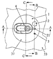
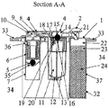
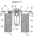
図1〜図4は、本発明の構成を示す図であるが、これによって本発明の範囲が限定されることはない。 1-4 is a figure which shows the structure of this invention, However, The range of this invention is not limited by this.
これらの図において、HDPE(高密度ポリエチレン)で作られたキャニスタ37のPA(ポリアミド)製円形カバー1が、ブリーザオリフィス2、ブリードピペット3及び排出可能な容積部11を備えた多目的弁4のヘッドを有し、このカバーは、HDPEで作られたタンクの壁33に溶接されている。この弁は、フロート6の下に位置した高密度スチールボール(鋼球)5を有し、ボール−フロート組立体は、スカートの形態をした管状部分7の内部に位置しており、この中でフロート6が自由に摺動する。高密度ボール5は、スカート7に固定されていて、スカートの上方にほぼ真ん中に位置した切頭円錐体を逆さまにした形態の有孔底部35上に載っている。スカート7、有孔底部35及びフロート6は、ポリアセタールで作られている。
In these figures, a PA (polyamide)
カバー1の近くに位置した箇所でスカート7の頂部内に設けられた通路36により、タンク34の内部とスカート7の内部が互いに連通している。スカート7は、クリップ留めによって弁4のヘッドに固定されている。弁4のヘッド内のフロート6の上には通路9が設けられ、この通路9は、エラストマーシール10によって構成され、この通路は、弁の内部を、タンクの壁33のレベルの上方で弁のヘッド内に位置したダクト8に連結している。フロート6の頂部は、これがシール10と接触した状態で、通路9を閉止することができる形状を有している。ダクト8は、キャビティ11内に開口し、キャビティはそれ自体これまた、カバー1に固定されている。
The interior of the
キャビティ11の底部のところには、シール13によって閉鎖された通路12が設けられ、このシールは、傘を逆さまにした形態をなしている。第2のキャビティ14が、キャビティ11の上に載っていて、高密度スチールボール16によって閉じられた通路によりこれに連結されており、それにより、タンクを、これが水平線に近い休止位置にあるときに、閉鎖できるようになっている。ボール16に密接して小さなサイズの第2の通路17が設けられており、この通路はそれ自体、サイズの小さな高密度ボール19を収容した小さなキャビティ18と連通している。
At the bottom of the
別の通路20が、小さなキャビティ18を主キャビティ11に連結している。カバー1内に組込まれたライン21が上方キャビティ14の延長をなしており、このラインは、ブリードピペット3の下に位置した別のキャビティ22内で終端している。このキャビティ22は、軟質のガス浸透性ポリウレタンフォーム23の層によって保護された活性炭グラニュール24の床の上に位置している。壁25が、グラニュール24の床を2つの領域に分離しており、その結果、2つの領域相互間を連通させることができるスペース26がそのベースとキャニスタ37の底部との間に形成されている。
Another
また、床24の頂部のところには、壁25の各側に位置した状態で軟質ポリウレタンフォームで作られた保護部材23,27が設けられている。保護部材23,27は、金属ばねを用いてグラニュールの床24の上方で定位置に保持されており、分かりやすくするためにかかる金属ばねの1つ28が図示されている。キャビティ22と対称のキャビティ29が、ブリーザオリフィス2の下で保護部材27の上方に位置している。このオリフィス2それ自体は、保護キャップ31の下に位置するピペット30で構成されている。グラニュール24、壁25、ポリウレタンフォーム保護部材23,27、及びキャビティ22,29は、カバー1で気密封止されたHDPE製の受け具32内に収納されている。受け具32の外部に位置し且つ主キャビティ11の外部に位置しているキャニスタ37の部品は、タンク34の内部と自由連通状態にある。
Further,
上述のキャニスタの作用は次の通りである。即ち、タンクが通常の休止位置にあるとき、タンク内に存在している液体燃料の頂部上に載っている気相は、通路36を介して、場合によっては、スカート7とフロート6との間の空間を介し、及び、通路9、ダクト8、キャビティ11、小さなキャビティ18、キャビティ14、ライン21、キャビティ22、活性炭24の床、キャビティ29及びピペット30を介して機外空気と連通状態にある。もし何等かの理由で、タンク内部のガス状雰囲気が、ほどほどの過剰圧力を受け、液体燃料のレベルが、通路36のレベルの下に位置する臨界レベルの下に位置したままであれば、燃料蒸気がいったん活性炭24内に保持されると、ガスのうち幾分かをこの通路36及び上述の経路を介して排出して機外空気中へ排出することによりタンクがガス抜きされる。この状態では、フロート6は、通路9を開いたままにするほど十分低い状態を保つ。もし、液体燃料がガス流により同伴されると、或いは、凝縮が起こると、この液体又はこの凝縮水は、容積部11内に保持されることになろう。容積部11内の保持された液体燃料のレベルが或る臨界重量を越えると、シール13は開いて、液体は、タンク34に戻る。
The operation of the above canister is as follows. That is, when the tank is in its normal rest position, the gas phase resting on the top of the liquid fuel present in the tank may pass through the
液体燃料のレベルが或る臨界レベルを越えた場合にタンク内部に過剰圧力が存在していれば、フロート6は上昇し、通路9を遮断し、通路36を燃料の下に浸漬させることができ、かくして、多量の燃料がダクト8に入るのが阻止され、キャビティ11の充填が阻止され、活性炭24の床が浸漬状態になるのが阻止され、しかも、燃料がタンクから漏れないようになる。
If there is excess pressure inside the tank when the liquid fuel level exceeds a certain critical level, the
タンクが偶発的に転倒すると、ボールはそのハウジングから出て、重力の作用でフロート6に押し当たり、かくして、タンクからの液体の漏れを止める。
If the tank accidentally falls, the ball exits its housing and strikes the
タンクが収納されている自動車両が水平の近くの位置で静止したままであり、タンク内の過剰圧力がほどほどの状態のままであるとき、キャビティ11内のガス状雰囲気は、狭い通路17を介してダクト14と連通し、ガス抜きが、上述したような通常のやり方で続く状態で、高密度ボール15は、その着座部上に載り、通路16を遮断する。
When the motor vehicle in which the tank is housed remains stationary at a position near horizontal and the excess pressure in the tank remains in a moderate state, the gaseous atmosphere in the
タンク内の過剰圧力が相当大きい場合、例えば、タンクが充填されている時に相当大きな過剰圧力が生じると、燃料蒸気に含まれた加圧ガスが、通路20に流入し、ボール19を押し、このボールは、キャビティ18内を上昇して通路17を閉鎖し、それによりタンクを閉鎖する。
When the excessive pressure in the tank is considerably large, for example, when a considerable excessive pressure is generated when the tank is filled, the pressurized gas contained in the fuel vapor flows into the
タンクが水平に近い位置で静止している場合にタンク内部が減圧状態になっていると、ボール19はキャビティ18内に落下して戻る。キャビティは、ボールがその最も下の箇所に到達しても、それにもかかわらず、通路20が依然として開いた状態のままであるような内部形状を有している。
If the tank is in a depressurized state when the tank is stationary at a position close to horizontal, the
車両が運動中である場合、高密度ボール15はその着座部から離れて通路16を開き、それにより、キャビティ14とライン21との直接的な連通が可能になる。
When the vehicle is in motion, the
1・・・カバー
2・・・ブリーザオリフィス
3・・・ブリードピペット
4・・・多目的弁
5・・・高密度スチールボール
6・・・フロート
7・・・スカート
8・・・ダクト
9・・・通路
10・・・エラストマーシール
11・・・キャビティ
12・・・通路
13・・・シール
14・・・第2のキャビティ
16・・・高密度スチールボール
17・・・第2の通路1
18・・・キャビティ
19・・・高密度ボール
20・・・通路
21・・・ライン
22・・・キャビティ
24・・・活性炭グラニュール床
25・・・壁
29・・・キャビティ
30・・・ピペット
31・・・保護キャップ
33・・・タンクの壁
34・・・タンク
35・・・有孔底部
36・・・通路
37・・・キャニスタ
DESCRIPTION OF
18 ...
Claims (9)
キャニスタは、前記タンクに燃料が充填された場合に少なくとも大部分が燃料表面より下に位置するように、少なくとも一部が前記タンク内に設けられているとともに前記タンクの過剰充填を阻止する過剰充填防止(OP)装置と連携し、
前記キャニスタは、少なくとも部分的に前記タンク内に設けられているとともに前記タンクが転倒した場合にタンクブリーザを閉止する装置(ROV)と連携していることを特徴とする燃料タンク。 A fuel tank having a canister containing a composition capable of holding fuel vapor,
The canister is at least partially provided in the tank and prevents overfilling of the tank so that at least most of the canister is located below the fuel surface when the tank is filled with fuel. Prevention (OP) device,
The fuel tank is characterized in that the canister is provided at least partially in the tank and is linked to a device (ROV) for closing a tank breather when the tank falls.
前記液気分離装置は、以下の形態、即ち、漏斗体、螺旋体、ラビリンスを形成する多数の壁から成る組織体のうち少なくとも1つを有していることを特徴とする請求項1〜3のいずれか一項に記載のタンク。 The liquid-gas separation device is located above the ROV device,
The liquid-gas separation device has at least one of the following forms: a funnel body, a spiral body, and a tissue body composed of multiple walls forming a labyrinth. The tank according to any one of the above.
前記タンクから前記キャニスタへの燃料蒸気の移動が前記アセンブリによって制御され、
前記アセンブリは少なくとも部分的に前記タンク内に配置されていることを特徴とする請求項1〜4のいずれか一項に記載のタンク。 The canister has a first passage (16) provided to close when the fuel tank is stationary, and is normally open, and the pressure in the tank exhibits a significant overpressure. In conjunction with an assembly comprising in parallel a second passageway (20) provided to close,
Movement of fuel vapor from the tank to the canister is controlled by the assembly;
5. A tank according to any one of the preceding claims, wherein the assembly is at least partially disposed within the tank.
Applications Claiming Priority (2)
| Application Number | Priority Date | Filing Date | Title |
|---|---|---|---|
| BE9900382 | 1999-06-01 | ||
| BE9900382A BE1012697A3 (en) | 1999-06-01 | 1999-06-01 | Fuel tank. |
Related Parent Applications (1)
| Application Number | Title | Priority Date | Filing Date |
|---|---|---|---|
| JP2010205797A Division JP5627966B2 (en) | 1999-06-01 | 2010-09-14 | Fuel tank |
Related Child Applications (1)
| Application Number | Title | Priority Date | Filing Date |
|---|---|---|---|
| JP2014239958A Division JP2015078696A (en) | 1999-06-01 | 2014-11-27 | Fuel tank |
Publications (1)
| Publication Number | Publication Date |
|---|---|
| JP2012197793A true JP2012197793A (en) | 2012-10-18 |
Family
ID=3891941
Family Applications (4)
| Application Number | Title | Priority Date | Filing Date |
|---|---|---|---|
| JP2001500110A Pending JP2003500606A (en) | 1999-06-01 | 2000-05-29 | Fuel tank |
| JP2010205797A Expired - Fee Related JP5627966B2 (en) | 1999-06-01 | 2010-09-14 | Fuel tank |
| JP2012123144A Pending JP2012197793A (en) | 1999-06-01 | 2012-05-30 | Fuel tank |
| JP2014239958A Pending JP2015078696A (en) | 1999-06-01 | 2014-11-27 | Fuel tank |
Family Applications Before (2)
| Application Number | Title | Priority Date | Filing Date |
|---|---|---|---|
| JP2001500110A Pending JP2003500606A (en) | 1999-06-01 | 2000-05-29 | Fuel tank |
| JP2010205797A Expired - Fee Related JP5627966B2 (en) | 1999-06-01 | 2010-09-14 | Fuel tank |
Family Applications After (1)
| Application Number | Title | Priority Date | Filing Date |
|---|---|---|---|
| JP2014239958A Pending JP2015078696A (en) | 1999-06-01 | 2014-11-27 | Fuel tank |
Country Status (9)
| Country | Link |
|---|---|
| US (1) | US6739350B1 (en) |
| EP (1) | EP1194689B1 (en) |
| JP (4) | JP2003500606A (en) |
| AT (1) | ATE291166T1 (en) |
| AU (1) | AU5676800A (en) |
| BE (1) | BE1012697A3 (en) |
| BR (1) | BR0011110A (en) |
| DE (1) | DE60018750T2 (en) |
| WO (1) | WO2000073644A1 (en) |
Families Citing this family (23)
| Publication number | Priority date | Publication date | Assignee | Title |
|---|---|---|---|---|
| ITTO20001147A1 (en) * | 2000-12-11 | 2002-06-11 | Ergom Materie Plastiche Spa | FUEL VAPOR RECOVERY SYSTEM FROM A VEHICLE TANK AND ITS EVAPORATOR GROUP. |
| US6557581B2 (en) * | 2001-03-01 | 2003-05-06 | Raviv Precision Injection Molding | Liquid fuel trap |
| DE10133400C2 (en) * | 2001-07-13 | 2003-08-07 | Siemens Ag | Fuel tank |
| FR2828442B1 (en) | 2001-08-13 | 2003-12-05 | Inergy Automotive Systems Man | MULTIFUNCTIONAL ASSEMBLY OF A FUEL SYSTEM, RESERVOIR COMPRISING SAID ASSEMBLY AND METHOD FOR MANUFACTURING THE SAME. |
| US7025222B2 (en) * | 2002-07-22 | 2006-04-11 | Toyoda Gosei Co., Ltd. | Cap device |
| US7493894B2 (en) * | 2004-02-13 | 2009-02-24 | Kelch Corporation | Tank assembly and components |
| US7086390B2 (en) * | 2004-11-05 | 2006-08-08 | Briggs & Stratton Corporation | Integrated fuel tank and vapor containment system |
| US7318424B2 (en) * | 2005-05-14 | 2008-01-15 | Miniature Precision Components, Inc. | Integrated vapor management and rollover valve for a fuel tank |
| FR2886366B1 (en) * | 2005-05-24 | 2007-07-06 | Inergy Automotive Systems Res | LIQUID TANK AIR SUPPLY SYSTEM |
| KR100949692B1 (en) * | 2005-09-15 | 2010-03-29 | 도요타 지도샤(주) | Internal combustion engine using hydrogen |
| US20070261752A1 (en) * | 2006-04-13 | 2007-11-15 | Stant Manufacturing Inc. | Multiple-layer fluid fuel apparatus |
| US8291929B2 (en) * | 2006-05-16 | 2012-10-23 | GM Global Technology Operations LLC | Dual float rollover valve |
| JP2008303729A (en) * | 2007-06-05 | 2008-12-18 | Aisan Ind Co Ltd | Evaporated fuel treatment device |
| US7574996B2 (en) * | 2007-10-23 | 2009-08-18 | Gm Global Technology Operations, Inc. | Fuel supply system with a gas adsorption device |
| KR100986063B1 (en) * | 2008-04-17 | 2010-10-07 | 현대자동차주식회사 | Canister for vehicle |
| EP2172531A1 (en) * | 2008-10-03 | 2010-04-07 | Siemens Aktiengesellschaft | Function test for a gas alarm system |
| CN104603442A (en) * | 2012-11-22 | 2015-05-06 | 丰田自动车株式会社 | Evaporated fuel processing device |
| CN103321790B (en) * | 2013-06-24 | 2016-02-03 | 南京德普瑞克催化器有限公司 | Miniature gasoline engine integral type overturning-preventing fuel tank cap charcoal tank |
| JP6153850B2 (en) * | 2013-11-01 | 2017-06-28 | 八千代工業株式会社 | Evaporative fuel processing equipment |
| JP6337300B2 (en) * | 2014-07-07 | 2018-06-06 | 三菱自動車工業株式会社 | Canister |
| EP3047997B1 (en) * | 2015-01-20 | 2018-01-10 | Magna Steyr Fuel Systems GesmbH | Venting valve |
| TWM514516U (en) * | 2015-08-28 | 2015-12-21 | Top 1 Green Dev Co Ltd | Fuel supply device and back oil utilization buffer bottle therein |
| CN114955288A (en) * | 2022-05-18 | 2022-08-30 | 浙江加宝新能源科技有限公司 | Intelligent plant fuel oil storage system |
Citations (9)
| Publication number | Priority date | Publication date | Assignee | Title |
|---|---|---|---|---|
| JPS62144725U (en) * | 1986-03-07 | 1987-09-12 | ||
| JPS62167728U (en) * | 1986-04-15 | 1987-10-24 | ||
| US4852761A (en) * | 1988-07-25 | 1989-08-01 | General Motors Corporation | In tank vapor storage canister |
| JPH0674118A (en) * | 1992-08-28 | 1994-03-15 | Toyota Motor Corp | Discharge deterrence device of evaporation fuel |
| JPH0777121A (en) * | 1993-08-23 | 1995-03-20 | Walbro Corp | Fuel tank with carbon canister and shut-off valve |
| JPH0842405A (en) * | 1994-07-28 | 1996-02-13 | Mitsubishi Motors Corp | Evaporated fuel treating equipment |
| JPH1030508A (en) * | 1995-12-30 | 1998-02-03 | Hyundai Motor Co Ltd | Evaporation gas control device for vehicle, and control method therefor |
| JPH1047188A (en) * | 1996-08-06 | 1998-02-17 | Aisan Ind Co Ltd | Fuel supplying device for internal combustion engine |
| JPH1113572A (en) * | 1997-06-20 | 1999-01-19 | Nok Corp | Liquid cutoff valve device |
Family Cites Families (15)
| Publication number | Priority date | Publication date | Assignee | Title |
|---|---|---|---|---|
| US3910302A (en) * | 1973-12-14 | 1975-10-07 | Chrysler Corp | Roll-over valve and vapor separator |
| JPS59165854A (en) * | 1983-03-09 | 1984-09-19 | Aisan Ind Co Ltd | Device for preventing fuel vaporization loss |
| JPS63104659U (en) * | 1986-12-26 | 1988-07-06 | ||
| DE3704641A1 (en) * | 1987-02-14 | 1988-03-24 | Daimler Benz Ag | Device for catching fuel vapours when filling a fuel tank |
| JPH0826825B2 (en) * | 1987-02-28 | 1996-03-21 | 日本電装株式会社 | Evaporative fuel processor |
| US5036823A (en) * | 1990-08-17 | 1991-08-06 | General Motors Corporation | Combination overfill and tilt shutoff valve system for vehicle fuel tank |
| US5146901A (en) * | 1992-02-03 | 1992-09-15 | General Motors Corporation | Vapor suppressing fuel handling system |
| JPH05254352A (en) * | 1992-03-12 | 1993-10-05 | Aisan Ind Co Ltd | Device for preventing fuel flow-out for fuel tank for vehicle |
| US5640989A (en) * | 1995-01-12 | 1997-06-24 | Nok Corporation | Fuel cut-off valve |
| US5579740A (en) * | 1995-01-20 | 1996-12-03 | Walbro Corporation | Fuel handling system |
| DE19510821C2 (en) * | 1995-03-24 | 1997-02-13 | Porsche Ag | Fuel tanks for vehicles, in particular motor vehicles |
| JPH09195861A (en) * | 1996-01-22 | 1997-07-29 | Mitsubishi Motors Corp | Fuel tank device |
| US5960817A (en) * | 1997-11-03 | 1999-10-05 | Walbro Corporation | Control valve and system for fuel vapor recovery |
| BE1012390A3 (en) * | 1999-01-18 | 2000-10-03 | Solvay | Marketing system to air tank liquid. |
| US6182693B1 (en) * | 1999-06-08 | 2001-02-06 | Delphi Technologies, Inc. | Vapor canister and fuel tank assembly |
-
1999
- 1999-06-01 BE BE9900382A patent/BE1012697A3/en not_active IP Right Cessation
-
2000
- 2000-05-29 WO PCT/EP2000/004924 patent/WO2000073644A1/en active IP Right Grant
- 2000-05-29 EP EP00942000A patent/EP1194689B1/en not_active Expired - Lifetime
- 2000-05-29 JP JP2001500110A patent/JP2003500606A/en active Pending
- 2000-05-29 BR BR0011110-4A patent/BR0011110A/en active Search and Examination
- 2000-05-29 AU AU56768/00A patent/AU5676800A/en not_active Abandoned
- 2000-05-29 US US09/980,013 patent/US6739350B1/en not_active Expired - Lifetime
- 2000-05-29 DE DE60018750T patent/DE60018750T2/en not_active Expired - Lifetime
- 2000-05-29 AT AT00942000T patent/ATE291166T1/en not_active IP Right Cessation
-
2010
- 2010-09-14 JP JP2010205797A patent/JP5627966B2/en not_active Expired - Fee Related
-
2012
- 2012-05-30 JP JP2012123144A patent/JP2012197793A/en active Pending
-
2014
- 2014-11-27 JP JP2014239958A patent/JP2015078696A/en active Pending
Patent Citations (9)
| Publication number | Priority date | Publication date | Assignee | Title |
|---|---|---|---|---|
| JPS62144725U (en) * | 1986-03-07 | 1987-09-12 | ||
| JPS62167728U (en) * | 1986-04-15 | 1987-10-24 | ||
| US4852761A (en) * | 1988-07-25 | 1989-08-01 | General Motors Corporation | In tank vapor storage canister |
| JPH0674118A (en) * | 1992-08-28 | 1994-03-15 | Toyota Motor Corp | Discharge deterrence device of evaporation fuel |
| JPH0777121A (en) * | 1993-08-23 | 1995-03-20 | Walbro Corp | Fuel tank with carbon canister and shut-off valve |
| JPH0842405A (en) * | 1994-07-28 | 1996-02-13 | Mitsubishi Motors Corp | Evaporated fuel treating equipment |
| JPH1030508A (en) * | 1995-12-30 | 1998-02-03 | Hyundai Motor Co Ltd | Evaporation gas control device for vehicle, and control method therefor |
| JPH1047188A (en) * | 1996-08-06 | 1998-02-17 | Aisan Ind Co Ltd | Fuel supplying device for internal combustion engine |
| JPH1113572A (en) * | 1997-06-20 | 1999-01-19 | Nok Corp | Liquid cutoff valve device |
Also Published As
| Publication number | Publication date |
|---|---|
| DE60018750T2 (en) | 2006-02-02 |
| US6739350B1 (en) | 2004-05-25 |
| JP2003500606A (en) | 2003-01-07 |
| EP1194689A1 (en) | 2002-04-10 |
| WO2000073644A1 (en) | 2000-12-07 |
| JP2010280384A (en) | 2010-12-16 |
| DE60018750D1 (en) | 2005-04-21 |
| ATE291166T1 (en) | 2005-04-15 |
| JP5627966B2 (en) | 2014-11-19 |
| AU5676800A (en) | 2000-12-18 |
| BR0011110A (en) | 2004-02-10 |
| BE1012697A3 (en) | 2001-02-06 |
| JP2015078696A (en) | 2015-04-23 |
| EP1194689B1 (en) | 2005-03-16 |
Similar Documents
| Publication | Publication Date | Title |
|---|---|---|
| JP5627966B2 (en) | Fuel tank | |
| US7168466B2 (en) | Safety system for liquid fuel tank | |
| JP5589011B2 (en) | Safety system for liquid fuel tank | |
| US6311675B2 (en) | Vent valve and fuel pump module | |
| KR100243522B1 (en) | Vapor recovery fuel tank system | |
| US6675779B2 (en) | Dual float valve for fuel tank vent with liquid carryover filter | |
| US7493894B2 (en) | Tank assembly and components | |
| US10076720B2 (en) | Cap with adsorption media | |
| JP4494572B2 (en) | Liquid tank ventilation system | |
| US7520293B2 (en) | Fuel storage system for a vehicle | |
| JP4917216B2 (en) | System for venting liquid tanks | |
| CN1837600B (en) | System and method for controlling fuel vapor emission in a small engine | |
| JPH11247729A (en) | Fuel vapor reducing-type fuel system | |
| JP4489209B2 (en) | Safety valve for liquid tank | |
| KR20110016965A (en) | Small engine fuel system | |
| US10473065B2 (en) | Fuel return device | |
| CN106907519B (en) | Valve device with weight control system | |
| WO2022174042A1 (en) | Rollover vent valve assembly |
Legal Events
| Date | Code | Title | Description |
|---|---|---|---|
| A977 | Report on retrieval |
Free format text: JAPANESE INTERMEDIATE CODE: A971007 Effective date: 20130816 |
|
| A131 | Notification of reasons for refusal |
Free format text: JAPANESE INTERMEDIATE CODE: A131 Effective date: 20130827 |
|
| A601 | Written request for extension of time |
Free format text: JAPANESE INTERMEDIATE CODE: A601 Effective date: 20131126 |
|
| A602 | Written permission of extension of time |
Free format text: JAPANESE INTERMEDIATE CODE: A602 Effective date: 20131205 |
|
| A521 | Request for written amendment filed |
Free format text: JAPANESE INTERMEDIATE CODE: A523 Effective date: 20140221 |
|
| A02 | Decision of refusal |
Free format text: JAPANESE INTERMEDIATE CODE: A02 Effective date: 20140729 |
|
| A521 | Request for written amendment filed |
Free format text: JAPANESE INTERMEDIATE CODE: A523 Effective date: 20141127 |
|
| A911 | Transfer to examiner for re-examination before appeal (zenchi) |
Free format text: JAPANESE INTERMEDIATE CODE: A911 Effective date: 20141204 |
|
| A912 | Re-examination (zenchi) completed and case transferred to appeal board |
Free format text: JAPANESE INTERMEDIATE CODE: A912 Effective date: 20150213 |
|
| A521 | Request for written amendment filed |
Free format text: JAPANESE INTERMEDIATE CODE: A523 Effective date: 20150205 |