JP2012197755A - Valve timing control device of internal combustion engine - Google Patents

Valve timing control device of internal combustion engine Download PDF

Info

Publication number
JP2012197755A
JP2012197755A JP2011063500A JP2011063500A JP2012197755A JP 2012197755 A JP2012197755 A JP 2012197755A JP 2011063500 A JP2011063500 A JP 2011063500A JP 2011063500 A JP2011063500 A JP 2011063500A JP 2012197755 A JP2012197755 A JP 2012197755A
Authority
JP
Japan
Prior art keywords
rotor
rotating body
rotator
electric motor
camshaft
Prior art date
Legal status (The legal status is an assumption and is not a legal conclusion. Google has not performed a legal analysis and makes no representation as to the accuracy of the status listed.)
Granted
Application number
JP2011063500A
Other languages
Japanese (ja)
Other versions
JP5693312B2 (en
Inventor
Akira Tadokoro
亮 田所
Naoki Kokubo
小久保  直樹
Junji Yamanaka
淳史 山中
Shinichi Kawada
真市 川田
Current Assignee (The listed assignees may be inaccurate. Google has not performed a legal analysis and makes no representation or warranty as to the accuracy of the list.)
Hitachi Astemo Ltd
Original Assignee
Hitachi Automotive Systems Ltd
Priority date (The priority date is an assumption and is not a legal conclusion. Google has not performed a legal analysis and makes no representation as to the accuracy of the date listed.)
Filing date
Publication date
Application filed by Hitachi Automotive Systems Ltd filed Critical Hitachi Automotive Systems Ltd
Priority to JP2011063500A priority Critical patent/JP5693312B2/en
Publication of JP2012197755A publication Critical patent/JP2012197755A/en
Application granted granted Critical
Publication of JP5693312B2 publication Critical patent/JP5693312B2/en
Expired - Fee Related legal-status Critical Current
Anticipated expiration legal-status Critical

Links

Images

Landscapes

  • Valve Device For Special Equipments (AREA)

Abstract

PROBLEM TO BE SOLVED: To provide a valve timing control device that can sufficiently suppress abnormal sound generated in a bearing for rotatably bearing a rotor of an electric motor.SOLUTION: A camshaft 2 is relatively rotated in relation to a timing sprocket 1 by rotational force of the electric motor 12 via a reduction gear mechanism. The electric motor 12 includes: a motor shaft 13 rotatably supported by a small diameter ball bearing 37, etc.; an iron core rotor 17 of a magnetic material provided on an outer periphery of the motor shaft 13 and provided with a plurality of slots in a peripheral direction; an electromagnetic coil 18 wound in the slots of the iron core rotor 17; and permanent magnets 14 and 15 fixed to an inner peripheral surface of a housing 5 and having inner peripheries opposed to the outer periphery of the iron core rotor 17. An axial direction center P of each of the permanent magnets 14 and 15 is offset by a prescribed distance α to the front in relation to an axial direction center P1 of the iron core rotor 17.

Description

本発明は、内燃機関の機関弁である吸気弁や排気弁の開閉タイミングを、電動モータを用いて可変制御する内燃機関のバルブタイミング制御装置に関する。   The present invention relates to a valve timing control device for an internal combustion engine that variably controls the opening / closing timing of intake valves and exhaust valves, which are engine valves of the internal combustion engine, using an electric motor.

近時、内燃機関のバルブタイミング制御装置にあっては、電動モータの回転力を、減速機構を介してカムシャフトに伝達することによってクランクシャフトとカムシャフトの相対回転位相の制御応答性や制御性を向上させるものが提供されている。   Recently, in a valve timing control device for an internal combustion engine, the responsiveness and controllability of the relative rotational phase of the crankshaft and the camshaft are transmitted by transmitting the rotational force of the electric motor to the camshaft via the speed reduction mechanism. Something to improve is provided.

例えば、以下の特許文献1に記載されたバルブタイミング制御装置に適用される前記電動モータとしては、直流モータが採用され、モータ軸の外周に設けられたロータにコイルが巻回されていると共に、モータハウジングの内周面に前記ロータの外周に対向配置されたステータとしての永久磁石が設けられている。前記モータ軸やロータは、ボールベアリングなどの軸受によって回転自在に軸受されている。   For example, as the electric motor applied to the valve timing control device described in Patent Document 1 below, a DC motor is employed, and a coil is wound around a rotor provided on the outer periphery of the motor shaft, A permanent magnet serving as a stator is provided on the inner peripheral surface of the motor housing so as to face the outer periphery of the rotor. The motor shaft and the rotor are rotatably supported by a bearing such as a ball bearing.

特開2010−255543号公報JP 2010-255543 A

しかしながら、前記公報記載のバルブタイミング制御装置は、機関駆動中において、機関弁を閉方向へ付勢するバルブスプリングのばね力などに起因してカムシャフトに交番トルクが発生することが知られている。このような交番トルクは、カムシャフトから前記ロータに伝達される。このため、たとえ前記永久磁石に対する前記ロータの軸方向の位置制御が精度良く行われているとしても、少なくとも前記軸受の軸方向のガタ分だけ振動して比較的大きな異音が発生してしまうといった技術的課題を招いている。   However, it is known that the valve timing control device described in the above publication generates an alternating torque on the camshaft due to the spring force of a valve spring that urges the engine valve in the closing direction during engine driving. . Such alternating torque is transmitted from the camshaft to the rotor. For this reason, even if the position control in the axial direction of the rotor with respect to the permanent magnet is performed with high accuracy, a relatively large noise is generated due to vibration at least by the axial backlash of the bearing. Inviting technical challenges.

本発明は、電動モータのロータを回転自在に軸受する軸受で発生する異音を十分に抑制し得る内燃機関のバルブタイミング制御装置を提供することを目的としている。   An object of the present invention is to provide a valve timing control device for an internal combustion engine that can sufficiently suppress abnormal noise generated in a bearing that rotatably supports a rotor of an electric motor.

本願請求項1に記載の発明は、バルブタイミング制御装置に用いられ電動モータが、ブラシ付きかブラシレスであるかに拘わらず、モータの出力軸に設けられて、周方向に複数のスロットが設けられた磁性材のロータと、電動モータのハウジングのモータ収容室の内周に設けられ、周方向に複数の磁極を有するスタータとしての例えば永久磁石と、を備え、この永久磁石の軸方向の中心が前記ロータの軸方向の中心に対してオフセット配置されていることを特徴としている。   The invention according to claim 1 of the present invention is provided on the output shaft of the motor, regardless of whether the electric motor used in the valve timing control device is brushed or brushless, and is provided with a plurality of slots in the circumferential direction. For example, a permanent magnet as a starter having a plurality of magnetic poles in the circumferential direction, and the center of the permanent magnet in the axial direction is provided at the inner periphery of the motor housing chamber of the housing of the electric motor. It is characterized by being offset from the axial center of the rotor.

この発明によれば、オフセット状態にある前記ロータが軸方向の一方側へ吸引されることによって、ロータを回転自在に軸受する軸受で発生する異音を十分に抑制することができる。   According to the present invention, the rotor in the offset state is attracted to one side in the axial direction, so that it is possible to sufficiently suppress abnormal noise generated in the bearing that rotatably supports the rotor.

本発明に係るバルブタイミング制御装置の一実施形態の要部拡大断面図である。It is a principal part expanded sectional view of one Embodiment of the valve timing control apparatus which concerns on this invention. 本発明に係るバルブタイミング制御装置の一実施形態を示す縦断面図である。It is a longitudinal section showing one embodiment of a valve timing control device concerning the present invention. 本実施形態における主要な構成部材を示す分解斜視図である。It is a disassembled perspective view which shows the main structural members in this embodiment. 図2のA−A線断面図である。It is the sectional view on the AA line of FIG. 図2のB−B線断面図である。FIG. 3 is a sectional view taken along line B-B in FIG. 2. 図2のC−C線断面図である。It is CC sectional view taken on the line of FIG. 図2のD矢視図である。FIG. 3 is a view taken in the direction of arrow D in FIG. 2. バルブタイミング制御装置の側面図である。It is a side view of a valve timing control device.

以下、本発明に係る内燃機関のバルブタイミング制御装置の実施形態を図面に基づいて説明する。なお、この実施形態では、内燃機関の吸気側の動弁装置に適用したものであるが、排気側の動弁装置に同様に適用することも可能である。   DESCRIPTION OF EMBODIMENTS Hereinafter, an embodiment of a valve timing control device for an internal combustion engine according to the present invention will be described with reference to the drawings. In this embodiment, the present invention is applied to the valve operating device on the intake side of the internal combustion engine, but it can also be similarly applied to the valve operating device on the exhaust side.

このバルブタイミング制御装置は、図2及び図3に示すように、内燃機関のクランクシャフトによって回転駆動する駆動回転体であるタイミングスプロケット1と、シリンダヘッド上に図外の軸受を介して回転自在に支持され、前記タイミングスプロケット1から伝達された回転力によって回転するカムシャフト2と、タイミングスプロケット1の前方位置に配置された図外のチェーンカバーに固定されたカバー部材3と、タイミングスプロケット1とカムシャフト2の間に配置されて、機関運転状態に応じて両者1,2の相対回転位相を変更する位相変更機構4と、を備えている。   As shown in FIGS. 2 and 3, this valve timing control device is rotatable on a timing sprocket 1 that is a drive rotating body that is rotationally driven by a crankshaft of an internal combustion engine, and on a cylinder head via a bearing not shown. A camshaft 2 that is supported and rotated by the rotational force transmitted from the timing sprocket 1, a cover member 3 fixed to a chain cover (not shown) disposed in front of the timing sprocket 1, the timing sprocket 1 and the cam And a phase change mechanism 4 that is disposed between the shafts 2 and changes the relative rotational phases of both 1 and 2 in accordance with the engine operating state.

前記タイミングスプロケット1は、全体が鉄系金属によって環状一体に形成され、内周面が段差径状のスプロケット本体1aと、該スプロケット本体1aの外周に一体に設けられて、巻回された図外のタイミングチェーンを介してクランクシャフトからの回転力を受けるギア部1bと、前記スプロケット本体1aの前端側に一体に設けられた環状部材19と、から構成されている。   The timing sprocket 1 is formed integrally with an iron-based metal in an annular shape, and the inner peripheral surface is integrally provided on the outer periphery of the sprocket body 1a with a stepped diameter, and is wound outside the drawing. The gear part 1b which receives the rotational force from a crankshaft via this timing chain, and the annular member 19 provided integrally on the front end side of the sprocket body 1a are configured.

また、このタイミングスプロケット1は、スプロケット本体1aと前記カムシャフト2の前端部に設けられた後述する従動部材9との間に、軸受である1つの大径ボールベアリング43が介装されており、この大径ボールベアリング43によって、タイミングスプロケット1と前記カムシャフト2が相対回転自在に支持されている。   The timing sprocket 1 includes a large-diameter ball bearing 43 as a bearing interposed between a sprocket body 1a and a driven member 9 described later provided at the front end of the camshaft 2. The large-diameter ball bearing 43 supports the timing sprocket 1 and the camshaft 2 so as to be relatively rotatable.

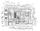
前記大径ボールベアリング43は、一般的な構造であって、図1〜図3に示すように、外輪43aと内輪43b及び該両輪43a、43bの間に介装されたボール43cとから構成されている。この大径ボールベアリング43は、前記外輪43aがスプロケット本体1aの内周側に固定されているのに対して内輪43bが後述する従動部材9の外周側に固定されている。   As shown in FIGS. 1 to 3, the large-diameter ball bearing 43 includes an outer ring 43a, an inner ring 43b, and a ball 43c interposed between the two wheels 43a and 43b. ing. In the large-diameter ball bearing 43, the outer ring 43a is fixed to the inner peripheral side of the sprocket body 1a, whereas the inner ring 43b is fixed to the outer peripheral side of the driven member 9 described later.

前記スプロケット本体1aは、内周側に、前記カムシャフト2側に開口した円環溝状の外輪固定部60が切欠形成されている。   In the sprocket body 1a, an annular groove-shaped outer ring fixing portion 60 opened to the camshaft 2 side is cut out on the inner peripheral side.

この外輪固定部60は、図1にも示すように、段差径状に形成されて、カムシャフト軸方向に延びた円環状の内周面60aと、該内周面60aの前記開口と反対側に一体に有し、径方向に沿って形成された第1固定段差面60bとから構成されている。前記内周面60aには、前記大径ボールベアリング43の外輪43aが軸方向から圧入されると共に、前記第1固定段差面60bには、圧入された前記外輪43aの軸方向の内端面43dが当接して、該外輪43aの軸方向一方側の位置決めをするようになっている。   As shown in FIG. 1, the outer ring fixing portion 60 is formed in a stepped diameter shape and has an annular inner peripheral surface 60 a extending in the camshaft axial direction, and the opposite side of the inner peripheral surface 60 a from the opening. And a first fixed step surface 60b formed along the radial direction. An outer ring 43a of the large-diameter ball bearing 43 is press-fitted from the axial direction into the inner peripheral surface 60a, and an axial inner end face 43d of the outer ring 43a is press-fitted into the first fixed step surface 60b. The outer ring 43a is positioned so as to contact one side in the axial direction.

前記環状部材19は、図1〜図3に示すように、前記スプロケット本体1aの前端部外周側に一体に設けられ、位相変更機構4の電動モータ12方向へ延出した円筒状に形成されていると共に、内周には、波形状の内歯19aが形成されている。この内歯19aは、円周方向に等間隔で連続的に複数形成されている。また、環状部材19の前端側には、電動モータ12の後述するハウジング5と一体の円環状の雌ねじ形成部6が配置されている。   As shown in FIGS. 1 to 3, the annular member 19 is integrally formed on the outer peripheral side of the front end portion of the sprocket body 1 a and is formed in a cylindrical shape extending in the direction of the electric motor 12 of the phase changing mechanism 4. In addition, wave-shaped internal teeth 19a are formed on the inner periphery. A plurality of the internal teeth 19a are continuously formed at equal intervals in the circumferential direction. An annular female screw forming portion 6 that is integral with a housing 5 (described later) of the electric motor 12 is disposed on the front end side of the annular member 19.

また、スプロケット本体1aの環状部材19と反対側の後端部には、円環状の保持プレート61が配置されている。この保持プレート61は、金属板材によって一体に形成され、図2に示すように、外径が前記スプロケット本体1aの外径とほぼ同一に設定されていると共に、内径が前記大径ボールベアリング43の径方向のほぼ中央付近の径に設定されている。したがって、保持プレート61の内周部61aは、前記外輪43aの軸方向の外端面43eに対して一定の隙間をもって覆うように対向配置されている。また、前記内周部61aの内周縁所定位置には、径方向内側、つまり中心軸方向に向かって突出したストッパ凸部61bが一体に設けられている。このストッパ凸部61bは、図5に示すように、ほぼ扇状に形成されて、先端縁61cが後述するストッパ溝2bの円弧状内周面に沿った円弧状に形成されている。さらに、前記保持プレート61の外周部には、前記各ボルト7が挿通する6つのボルト挿通孔61dが周方向の等間隔位置に貫通形成されている。   An annular holding plate 61 is disposed at the rear end of the sprocket body 1a opposite to the annular member 19. The holding plate 61 is integrally formed of a metal plate material. As shown in FIG. 2, the outer diameter is set to be substantially the same as the outer diameter of the sprocket body 1 a and the inner diameter is the same as that of the large-diameter ball bearing 43. It is set to a diameter near the center in the radial direction. Accordingly, the inner peripheral portion 61a of the holding plate 61 is disposed so as to cover the outer end surface 43e in the axial direction of the outer ring 43a with a certain gap. Further, a stopper convex portion 61b protruding inward in the radial direction, that is, in the central axis direction is integrally provided at a predetermined position on the inner peripheral edge of the inner peripheral portion 61a. As shown in FIG. 5, the stopper convex portion 61b is formed in a substantially fan shape, and the tip edge 61c is formed in an arc shape along an arcuate inner peripheral surface of a stopper groove 2b described later. Further, six bolt insertion holes 61d through which the respective bolts 7 are inserted are formed in the outer peripheral portion of the holding plate 61 at equal intervals in the circumferential direction.

さらに、前記保持プレート61の内面と該内面に対向する前記大径ボールベアリング43の外輪43aの外端面43eとの間には、円環状のスペーサ62が介装されている。このスペーサ62は、前記保持プレート61を前記各ボルト7によって共締め固定した際に、保持プレート61の内面から前記外輪43aの外端面43eへ僅かな押し付け力を付与するものであるが、この肉厚は外輪43aの外端面43eと保持プレート61との間に、外輪43aの軸方向移動許容範囲内の微小隙間が形成される程度の厚さに設定されている。   Further, an annular spacer 62 is interposed between the inner surface of the holding plate 61 and the outer end surface 43e of the outer ring 43a of the large-diameter ball bearing 43 facing the inner surface. The spacer 62 applies a slight pressing force from the inner surface of the holding plate 61 to the outer end surface 43e of the outer ring 43a when the holding plate 61 is fastened and fixed together by the bolts 7. The thickness is set to such a thickness that a minute gap within the allowable range of axial movement of the outer ring 43a is formed between the outer end surface 43e of the outer ring 43a and the holding plate 61.

前記スプロケット本体1a(環状部材19)及び保持プレート61のそれぞれの外周部には、ボルト挿通孔1c、61dが周方向のほぼ等間隔位置に6つ貫通形成されている。また、前記雌ねじ形成部6には、各ボルト挿通孔1c、61dと対応した位置に6つの雌ねじ孔6aが形成されており、これらに挿通した6本のボルト7によって前記三者61、1、6(ハウジング5)が共締め固定されている。   Six bolt insertion holes 1c and 61d are formed through the outer peripheral portions of the sprocket body 1a (annular member 19) and the holding plate 61 at substantially equal intervals in the circumferential direction. The female screw forming portion 6 has six female screw holes 6a formed at positions corresponding to the bolt insertion holes 1c and 61d. The six bolts 7 inserted through these female screws 6a and 6d have the three members 61, 1, 6 (housing 5) is fastened together.

なお、前記スプロケット本体1a及び環状部材19が、後述する減速機構8のケーシングとして構成されている。   The sprocket body 1a and the annular member 19 are configured as a casing of the speed reduction mechanism 8 described later.

また、前記スプロケット本体1aと前記環状部材19、保持プレート61及び雌ねじ形成部6は、それぞれの外径がほぼ同一に設定されている。   The sprocket body 1a, the annular member 19, the holding plate 61, and the female thread forming portion 6 are set to have substantially the same outer diameter.

前記カバー部材3は、アルミニウム合金材によってカップ状に一体に形成されて、前端部に形成された膨出部3aが前記ハウジング5の前端部を覆うように設けられていると共に、前記膨出部3aの外周部側には円筒壁3bが軸方向に沿って一体に形成されている。この円筒壁3bは、図2、図3にも示すように、内部に保持用孔3cが形成されて、この保持用孔3cの内周面が後述するブラシ保持体28のガイド面として構成されている。   The cover member 3 is integrally formed in a cup shape with an aluminum alloy material, and a bulging portion 3a formed at the front end portion is provided so as to cover the front end portion of the housing 5, and the bulging portion A cylindrical wall 3b is integrally formed along the axial direction on the outer peripheral side of 3a. As shown in FIGS. 2 and 3, the cylindrical wall 3 b has a holding hole 3 c formed therein, and the inner peripheral surface of the holding hole 3 c is configured as a guide surface of a brush holder 28 described later. ing.

また、カバー部材3は、図2に示すように、外周に形成されたフランジ部3dに6つのボルト挿通孔3eが貫通形成され、この各ボルト挿通孔3eに挿通された図外のボルトによって前記チェーンカバーに固定されている。   In addition, as shown in FIG. 2, the cover member 3 has six bolt insertion holes 3e formed through the flange portion 3d formed on the outer periphery, and the bolts outside the figure inserted through the bolt insertion holes 3e. It is fixed to the chain cover.

前記膨出部3aの外周側の段差部内周面と前記ハウジング5の外周面との間には、図2にも示すように、シール部材である大径なオイルシール50が介装されている。この大径オイルシール50は、横断面ほぼコ字形状に形成されて、合成ゴムの基材の内部に芯金が埋設されていると共に、外周側の円環状基部が前記カバー部材3の内周面に設けられた段差円環部3hに嵌着固定されている。   As shown in FIG. 2, a large-diameter oil seal 50 as a seal member is interposed between the inner peripheral surface of the stepped portion on the outer peripheral side of the bulging portion 3 a and the outer peripheral surface of the housing 5. . The large-diameter oil seal 50 is formed in a substantially U-shaped cross section, a core metal is embedded in the synthetic rubber base material, and an annular base on the outer peripheral side is the inner periphery of the cover member 3. It is fitted and fixed to a step ring portion 3h provided on the surface.

前記ハウジング5は、鉄系金属材をプレス成形によって有底筒状に形成された筒状部であるハウジング本体5aと、該ハウジング本体5aの前端開口を封止する封止プレート11と、を備えている。   The housing 5 includes a housing main body 5a that is a cylindrical portion formed by pressing a ferrous metal material into a bottomed cylindrical shape, and a sealing plate 11 that seals a front end opening of the housing main body 5a. ing.

前記ハウジング本体5aは、後端側に円板状の底部5bを有し、該底部5bのほぼ中央に後述の偏心軸部39を挿通する大径な軸部挿通孔5cが形成されていると共に、該軸部挿通孔5cの孔縁には、カムシャフト2軸方向へ突出した円筒状の延出部5dが一体に設けられている。また、前記底部5bの前端面外周側には、前記雌ねじ形成部6が一体に設けられている。   The housing body 5a has a disk-like bottom portion 5b on the rear end side, and a large-diameter shaft insertion hole 5c through which an eccentric shaft portion 39 (described later) is inserted is formed at substantially the center of the bottom portion 5b. A cylindrical extension 5d protruding in the axial direction of the camshaft 2 is integrally provided at the hole edge of the shaft insertion hole 5c. The female thread forming portion 6 is integrally provided on the outer peripheral side of the front end surface of the bottom portion 5b.

前記カムシャフト2は、外周に図外の吸気弁を開作動させる一気筒当たり2つの駆動カムを有していると共に、前端部に前記フランジ部2aが一体に設けられている。   The camshaft 2 has two drive cams per cylinder for opening an intake valve (not shown) on the outer periphery, and the flange portion 2a is integrally provided at the front end.

このフランジ部2aは、図1及び図2に示すように、外径が後述する従動部材9の固定端部9aの外径よりも僅かに大きく設定されて、各構成部品の組み付け後に、前端面2eの外周部が前記大径ボールベアリング43の内輪43bの軸方向外端面43gに当接配置されるようになっている。また、前端面2eが従動部材9に軸方向から当接した状態でカムボルト10によって軸方向から結合されている。   As shown in FIGS. 1 and 2, the flange portion 2a is set to have an outer diameter slightly larger than an outer diameter of a fixed end portion 9a of a driven member 9 to be described later. The outer peripheral portion of 2e is arranged in contact with the axially outer end surface 43g of the inner ring 43b of the large-diameter ball bearing 43. Further, the front end face 2e is coupled from the axial direction by the cam bolt 10 in a state where the front end face 2e is in contact with the driven member 9 from the axial direction.

また、前記フランジ部2aの外周には、図5に示すように、前記保持プレート61のストッパ凸部61bが係入するストッパ凹溝2bが円周方向に沿って形成されている。このストッパ凹溝2bは、円周方向へ所定長さの円弧状に形成されて、この長さ範囲で回動したストッパ凸部61bの両端縁が周方向の対向縁2c、2dにそれぞれ当接することによって、タイミングスプロケット1に対するカムシャフト2の最大進角側あるいは最大遅角側の相対回転位置を規制するようになっている。   Further, as shown in FIG. 5, a stopper concave groove 2b into which the stopper convex portion 61b of the holding plate 61 is engaged is formed on the outer periphery of the flange portion 2a along the circumferential direction. The stopper concave groove 2b is formed in a circular arc shape having a predetermined length in the circumferential direction, and both end edges of the stopper convex portion 61b rotated within this length range abut against the circumferential opposite edges 2c and 2d, respectively. Thus, the relative rotational position of the camshaft 2 on the maximum advance angle side or the maximum retard angle side with respect to the timing sprocket 1 is regulated.

なお、前記ストッパ凸部61bは、前記保持プレート61の大径ボールベアリング43の外輪43aに軸方向外側から対向して固定する部位よりもカムシャフト2側に離間して配置されて、前記従動部材9の固定端部9aとは非接触状態になっている。したがって、ストッパ凸部61bと固定端部9aとの干渉を十分抑制できる。   The stopper convex portion 61b is disposed at a position closer to the camshaft 2 than a portion of the holding plate 61 fixed to the outer ring 43a of the large-diameter ball bearing 43 facing the outer side in the axial direction. 9 is in a non-contact state with the fixed end 9a. Therefore, interference between the stopper convex portion 61b and the fixed end portion 9a can be sufficiently suppressed.

前記ストッパ凸部61bとストッパ凹溝2bによってストッパ機構が構成されている。   The stopper convex portion 61b and the stopper concave groove 2b constitute a stopper mechanism.

前記カムボルト10は、図2に示すように、頭部10aの軸部10b側の端面に円環状のワッシャ部10cが配置されていると共に、軸部10bの外周に前記カムシャフト2の端部から内部軸方向に形成された雌ねじ部に螺着する雄ねじ部10dが形成されている。   As shown in FIG. 2, the cam bolt 10 has an annular washer portion 10c disposed on the end surface of the head portion 10a on the shaft portion 10b side, and an outer periphery of the shaft portion 10b from the end portion of the camshaft 2. A male screw portion 10d that is screwed into a female screw portion formed in the inner axial direction is formed.

前記従動部材9は、鉄系金属材によって一体に形成され、図2に示すように、前端側に形成された円板状の固定端部9aと、該固定端部9aの内周前端面から軸方向へ突出した円筒部9bと、前記固定端部9aの外周部に一体に形成されて、複数のローラ48を保持する円筒状の保持器41とから構成されている。   The driven member 9 is integrally formed of a ferrous metal material, and as shown in FIG. 2, a disc-shaped fixed end portion 9a formed on the front end side, and an inner peripheral front end surface of the fixed end portion 9a. A cylindrical portion 9b protruding in the axial direction and a cylindrical retainer 41 that is formed integrally with the outer peripheral portion of the fixed end portion 9a and holds a plurality of rollers 48 are formed.

前記固定端部9aは、後端面が前記カムシャフト2のフランジ部2aの前端面に当接配置されて、前記カムボルト10の軸力によってフランジ部2aに軸方向から圧接固定されている。   The fixed end portion 9 a has a rear end surface disposed in contact with a front end surface of the flange portion 2 a of the camshaft 2, and is pressed and fixed to the flange portion 2 a from the axial direction by the axial force of the cam bolt 10.

前記円筒部9bは、図2に示すように、中央に前記カムボルト10の軸部10bが挿通される挿通孔9dが貫通形成されていると共に、外周側にニードルベアリング38が設けられている。   As shown in FIG. 2, the cylindrical portion 9b has a through hole 9d through which the shaft portion 10b of the cam bolt 10 is inserted, and a needle bearing 38 on the outer peripheral side.

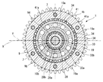
前記保持器41は、図1〜図4に示すように、前記固定端部9aの外周部前端から断面ほぼL字形状に折曲されて、前記円筒部9bと同方向へ突出した有底円筒状に形成されている。この保持器41の筒状先端部41aは、前記雌ねじ形成部6と前記延出部5dとの間に形成された円環状の凹部である空間部44を介してハウジング5の底部5b方向へ延出している。また、前記先端部41aの周方向のほぼ等間隔位置に、前記複数のローラ48をそれぞれ転動自在に保持するローラ保持部であるほぼ長方形状の複数のローラ保持孔41bが周方向の等間隔位置に形成されている。このローラ保持孔41b(ローラ48)は、その全体の数が前記環状部材19の内歯19aの全体の歯数よりも1つ少なくなっている。   1 to 4, the retainer 41 is bent into a substantially L-shaped cross section from the front end of the outer peripheral portion of the fixed end portion 9a, and protrudes in the same direction as the cylindrical portion 9b. It is formed in a shape. The cylindrical tip 41a of the retainer 41 extends in the direction of the bottom 5b of the housing 5 via a space 44 that is an annular recess formed between the female screw forming portion 6 and the extending portion 5d. I'm out. In addition, a plurality of substantially rectangular roller holding holes 41b, which are roller holding portions for holding the plurality of rollers 48 in a freely rolling manner, are arranged at substantially equal intervals in the circumferential direction of the tip end portion 41a. Formed in position. The total number of the roller holding holes 41b (rollers 48) is one less than the total number of teeth of the inner teeth 19a of the annular member 19.

そして、前記固定端部9aの外周部と保持器41の底部側結合部との間には、前記大径ボールベアリング43の内輪43bを固定する内輪固定部63が切欠形成されている。   An inner ring fixing portion 63 for fixing the inner ring 43b of the large-diameter ball bearing 43 is formed in a notch between the outer peripheral portion of the fixed end portion 9a and the bottom side coupling portion of the cage 41.

この内輪固定部63は、図1にも示すように、前記外輪固定部60と径方向から対向した段差状に切欠形成されて、カムシャフト軸方向に延びた円環状の外周面63aと、該外周面63aの前記開口と反対に一体に有し、径方向に沿って形成された第2固定段差面63bとから構成されている。前記外周面63aには、大径ボールベアリング43の内輪43bが軸方向から圧入されると共に、前記第2固定段差面63bには、圧入された前記内輪43bの内端面43fが当接して軸方向の位置決めされるようになっている。   As shown in FIG. 1, the inner ring fixing portion 63 is formed in a stepped shape facing the outer ring fixing portion 60 in the radial direction, and has an annular outer peripheral surface 63a extending in the camshaft axial direction. The outer peripheral surface 63a is integrally formed opposite to the opening, and includes a second fixed step surface 63b formed along the radial direction. An inner ring 43b of a large-diameter ball bearing 43 is press-fitted from the axial direction to the outer peripheral surface 63a, and an inner end face 43f of the press-fitted inner ring 43b abuts on the second fixed step surface 63b. It is designed to be positioned.

前記位相変更機構4は、前記カムシャフト2のほぼ同軸上前端側に配置されたアクチュエータである前記電動モータ12と、該電動モータ12の回転速度を減速してカムシャフト2に伝達する前記減速機構8と、から構成されている。   The phase changing mechanism 4 includes the electric motor 12 that is an actuator disposed on the substantially coaxial front end side of the camshaft 2, and the speed reducing mechanism that reduces the rotational speed of the electric motor 12 and transmits it to the camshaft 2. 8.

前記電動モータ12は、図2及び図3に示すように、ブラシ付きのDCモータであって、前記タイミングスプロケット1と一体に回転するヨークである前記ハウジング5と、該ハウジング5の内部に回転自在に設けられた中間回転体であるモータ軸13(出力軸)と、ハウジング5の内周面に固定されたステータである半円弧状の一対の永久磁石14,15と、前記封止プレート11に固定された固定子16と、を備えている。   As shown in FIGS. 2 and 3, the electric motor 12 is a brushed DC motor, which is a yoke that rotates integrally with the timing sprocket 1, and the housing 5 is rotatable inside the housing 5. A motor shaft 13 (output shaft) that is an intermediate rotating body provided on the inner surface of the housing 5, a pair of semicircular arc permanent magnets 14 and 15 that are stators fixed to the inner peripheral surface of the housing 5, and the sealing plate 11 A fixed stator 16.

前記モータ軸13は、図1にも示すように、段差円筒状に形成されてアーマチュアとして機能し、軸方向のほぼ中央位置に形成された段差部13cを介してカムシャフト2側の大径部13aと、ブラシ保持体28側の小径部13bとから構成されている。また、前記大径部13aの外周に鉄心ロータ17が固定されていると共に、該大径部13aの内部に偏心軸部39が軸方向から圧入固定されて、前記段差部13cの内面によって偏心軸部39の軸方向の位置決めがさせるようになっている。一方、前記小径部13bの外周には、コミュテータ20が軸方向から圧入固定されて前記段差部13cの外面によって軸方向の位置決めがされている。   As shown in FIG. 1, the motor shaft 13 is formed in a stepped cylindrical shape and functions as an armature, and has a large diameter portion on the camshaft 2 side through a stepped portion 13c formed at a substantially central position in the axial direction. 13a and a small diameter portion 13b on the brush holder 28 side. Further, the iron core rotor 17 is fixed to the outer periphery of the large diameter portion 13a, and an eccentric shaft portion 39 is press-fitted and fixed in the large diameter portion 13a from the axial direction, and an eccentric shaft is formed by the inner surface of the step portion 13c. The portion 39 is positioned in the axial direction. On the other hand, on the outer periphery of the small diameter portion 13b, the commutator 20 is press-fitted and fixed from the axial direction and is positioned in the axial direction by the outer surface of the step portion 13c.

このように、前記段差部13cの内外面によって前記偏心軸部39とコミュテータ20の両方の軸方向の位置決めができるので、組み付け作業が容易になると共に、位置決め精度が向上する。   As described above, since both the eccentric shaft portion 39 and the commutator 20 can be positioned in the axial direction by the inner and outer surfaces of the step portion 13c, the assembling work is facilitated and the positioning accuracy is improved.

前記鉄心ロータ17は、複数の磁極を持つ磁性材によって形成され、外周に形成されたスロットには電磁コイル18が巻回されている。この電磁コイル18は、カムシャフト2側のコイル部18aが前記ハウジング5の底部5b前端面の凹部5e内に収容された形で軸方向から近接配置されている。   The iron core rotor 17 is formed of a magnetic material having a plurality of magnetic poles, and an electromagnetic coil 18 is wound around a slot formed on the outer periphery. The electromagnetic coil 18 is disposed close to the axial direction in such a manner that the coil portion 18a on the camshaft 2 side is housed in the recess 5e on the front end surface of the bottom 5b of the housing 5.

一方、前記コミュテータ20には、前記鉄心ロータ17の極数と同数に分割された各セグメントに前記電磁コイル18が電気的に接続されている。   On the other hand, the commutator 20 is electrically connected to the electromagnetic coil 18 in each segment divided into the same number as the number of poles of the iron core rotor 17.

前記永久磁石14,15は、全体が円筒状に形成されて円周方向に複数の磁極を有していると共に、その軸方向の位置が前記鉄心ロータ17の固定位置よりも前方にオフセット配置されている。   The permanent magnets 14, 15 are formed in a cylindrical shape as a whole and have a plurality of magnetic poles in the circumferential direction, and their axial positions are offset from the fixed position of the iron core rotor 17. ing.

具体的に説明すれば、前記永久磁石14,15は、図1及び図2に示すように、その軸方向の中心Pが前記鉄心ロータ17の軸方向の中心P1に対して所定の距離α分だけ前方向、つまり、前記固定子16側にオフセット配置されている。   More specifically, as shown in FIGS. 1 and 2, the permanent magnets 14 and 15 have an axial center P that is a predetermined distance α away from the axial center P1 of the iron core rotor 17. Only in the forward direction, that is, offset to the stator 16 side.

また、これによって、前記永久磁石14,15の前端部14a、15aが、径方向で前記コミュテータ20や固定子16の後述する第1ブラシ25a、25bなどとオーバーラップするように配置されている。   Further, by this, the front end portions 14a and 15a of the permanent magnets 14 and 15 are arranged so as to overlap with the first brushes 25a and 25b described later of the commutator 20 and the stator 16 in the radial direction.

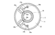
前記固定子16は、図6に示すように、前記封止プレート11の内周側に一体的に設けられた円板状の樹脂プレート22と、該樹脂プレート22の内側に設けられた一対の樹脂ホルダー23a、23bと、該各樹脂ホルダー23a、23bの内部に径方向に沿って摺動自在に収容配置されて、コイルスプリング24a、24bのばね力で各先端面が前記コミュテータ20の外周面に径方向から弾接する切換ブラシ(整流子)である第1ブラシ25a、25bと、前記樹脂ホルダー23a、23bの前端面に、各外端面を露出した状態で埋設固定された内外二重の円環状のスリップリング26a、26bと、前記各第1ブラシ25a、25bと各スリップリング26a、26bを電気的に接続するピグテールハーネス27a、27bと、から主として構成されている。なお、前記スリップリング26a、26bが給電機構の一部を構成し、また、前記第1ブラシ25a、25bやコミュテータ20、ピグテールハーネス27a、27bなどが通電切換手段として構成されている。   As shown in FIG. 6, the stator 16 includes a disk-shaped resin plate 22 integrally provided on the inner peripheral side of the sealing plate 11 and a pair of resin plates 22 provided on the inner side of the resin plate 22. Resin holders 23a and 23b and the resin holders 23a and 23b are slidably accommodated in the radial direction, and the distal end surfaces thereof are outer peripheral surfaces of the commutator 20 by the spring force of the coil springs 24a and 24b. First and second brushes 25a and 25b, which are switching brushes (commutators) that elastically contact with each other from the radial direction, and inner and outer double circles embedded and fixed to the front end surfaces of the resin holders 23a and 23b with the respective outer end surfaces exposed. Annular slip rings 26a, 26b, and pigtail harnesses 27a, 27b that electrically connect the first brushes 25a, 25b to the slip rings 26a, 26b, respectively. It is constructed by. The slip rings 26a and 26b constitute a part of the power feeding mechanism, and the first brushes 25a and 25b, the commutator 20, the pigtail harnesses 27a and 27b, and the like are configured as energization switching means.

前記封止プレート11は、前記ハウジング5の前端部内周に形成された凹状段差部にかしめによって位置決め固定されている。また、中央位置には、モータ軸13の一端部などが挿通される軸挿通孔11aが貫通形成されている。   The sealing plate 11 is positioned and fixed by caulking to a concave step formed on the inner periphery of the front end of the housing 5. Further, a shaft insertion hole 11a through which one end of the motor shaft 13 and the like are inserted is formed at the center position.

前記膨出部3aには、合成樹脂材によって一体的にモールドされた給電機構であるブラシ保持体28が固定されている。   A brush holder 28 that is a power feeding mechanism integrally molded with a synthetic resin material is fixed to the bulging portion 3a.

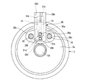
このブラシ保持体28は、図2、図3及び図8にも示すように、側面視ほぼL字形状に形成され、前記保持用孔3cに挿入されるほぼ円筒状のブラシ保持部28aと、該ブラシ保持部28aの上端部に有するコネクタ部28bと、前記ブラシ保持部28aの両側に一体に突設されて、前記膨出部3aに固定される一対のブラケット部28c、28cと、前記ブラシ保持体28の内部に大部分が埋設された一対の端子片31、31と、から主として構成されている。   As shown in FIGS. 2, 3 and 8, the brush holder 28 is formed in a substantially L shape in a side view, and has a substantially cylindrical brush holding portion 28a inserted into the holding hole 3c. A connector portion 28b at the upper end of the brush holding portion 28a; a pair of bracket portions 28c, 28c that are integrally projected on both sides of the brush holding portion 28a and fixed to the bulging portion 3a; and the brush The main body is mainly composed of a pair of terminal pieces 31 and 31 which are mostly embedded in the holding body 28.

前記一対の端子片31,31は、上下方向に沿って平行かつクランク状に形成されて、一方側(下端側)の各端子31a、31aが前記ブラシ保持部28aの底部側に露出状態で配置されている一方、他方側(上端側)の各端子31b、31bが前記コネクタ部28bの雌型嵌合溝28d内に突設されている。また、前記他方側端子31a、31bは、図外の雄端子を介してバッテリー電源に電気的に接続されている。   The pair of terminal pieces 31 and 31 are formed in a parallel and crank shape along the vertical direction, and the terminals 31a and 31a on one side (lower end side) are arranged in an exposed state on the bottom side of the brush holding portion 28a. On the other hand, the terminals (31b, 31b) on the other side (upper end side) protrude from the female fitting groove 28d of the connector portion 28b. The other terminals 31a and 31b are electrically connected to a battery power source via male terminals (not shown).

前記ブラシ保持部28aは、ほぼ水平方向(軸方向)に延設されて、内部の上下位置に形成された円柱状の貫通孔内にスリーブ状の摺動部29a、29bが固定されていると共に、該各摺動部29a、29bの内部に、各先端面が前記各スリップリング26a、26bに軸方向からそれぞれ当接する第2ブラシ30a、30bが軸方向へ摺動自在に保持されている。   The brush holding portion 28a extends substantially in the horizontal direction (axial direction), and sleeve-like sliding portions 29a and 29b are fixed in cylindrical through holes formed at the upper and lower positions inside the brush holding portion 28a. The second brushes 30a and 30b whose tip surfaces abut on the slip rings 26a and 26b from the axial direction are held in the sliding portions 29a and 29b so as to be slidable in the axial direction.

この各第2ブラシ30a、30bは、ほぼ長方体状に形成されて、各貫通孔の底部側に臨む前記一方側端子31a、31aとの間に弾装された付勢部材である第2コイルスプリング32a、32bのばね力によってそれぞれ前記各スリップリング26a、26b方向に付勢されている。   Each of the second brushes 30a and 30b is formed in a substantially rectangular shape and is a second biasing member that is elastically mounted between the one side terminals 31a and 31a facing the bottom side of each through hole. The coil springs 32a and 32b are urged toward the slip rings 26a and 26b by the spring force of the coil springs 32a and 32b, respectively.

また、前記第2ブラシ30a、30bの後端部と前記一方側端子31a、31aとの間には、可撓性を有する一対のピグテールハーネス33a、33bが溶接固定されて、前記両者を電気的に接続している。このピグテールハーネス33a、33bは、その長さが前記第2ブラシ30a、30bが前記各コイルスプリング32a、32bによって最大に進出した際に、前記各摺動部29a、29bから脱落しないように、その最大摺動位置を規制する長さに設定されている。   In addition, a pair of flexible pigtail harnesses 33a and 33b are fixed by welding between the rear end portions of the second brushes 30a and 30b and the one-side terminals 31a and 31a. Connected to. The pigtail harnesses 33a and 33b have a length so that the second brushes 30a and 30b do not fall off the sliding portions 29a and 29b when the second brushes 30a and 30b are advanced to the maximum by the coil springs 32a and 32b. The length is set to regulate the maximum sliding position.

また、前記ブラシ保持部28aの基部側外周に形成された円環状の嵌着溝内に、環状シール部材34が嵌着保持されており、前記ブラシ保持部28aが前記保持用孔3cに挿通された際に、前記シール部材34が前記円筒壁3bの先端面に弾接してブラシ保持部28a内をシールするようになっている。   An annular seal member 34 is fitted and held in an annular fitting groove formed on the base side outer periphery of the brush holding portion 28a, and the brush holding portion 28a is inserted into the holding hole 3c. In this case, the seal member 34 is in elastic contact with the tip surface of the cylindrical wall 3b to seal the inside of the brush holding portion 28a.

前記コネクタ部28bは、上端部に図外の雄型端子が挿入される前述した嵌合溝28dに臨む前記他方側端子31b、31bが前記雄型端子を介して図外のコントロールユニットに電気的に接続されている。   In the connector portion 28b, the other side terminals 31b and 31b facing the fitting groove 28d in which the male terminal (not shown) is inserted into the upper end portion are electrically connected to the control unit (not shown) via the male terminal. It is connected to the.

前記ブラケット部28c、28cは、ほぼ三角形状に形成されて、両側部にボルト挿通孔28e、28eが貫通形成されている。この各ボルト挿通孔28e、28eには、前記膨出部3aに形成された一対の雌ねじ孔3f、3fに螺着する各ボルト36、36が挿通されて各ブラケット部28c、28cを介して前記ブラシ保持体28が膨出部3aに固定されるようになっている。   The bracket portions 28c, 28c are formed in a substantially triangular shape, and bolt insertion holes 28e, 28e are formed through both sides. The bolt insertion holes 28e, 28e are respectively inserted with bolts 36, 36 which are screwed into a pair of female screw holes 3f, 3f formed in the bulging portion 3a, and are inserted into the bolt insertion holes 28e, 28e via the bracket portions 28c, 28c. The brush holder 28 is fixed to the bulging portion 3a.

前記モータ軸13と偏心軸部39は、前記カムボルト10の頭部10a側の軸部10bの外周面に設けられた小径ボールベアリング37と、前記従動部材9の円筒部9bの外周面に設けられて小径ボールベアリング37の軸方向側部に配置された前記ニードルベアリング38とによって回転自在に支持されている。この小径ボールベアリング37とニードルベアリング38によって軸受機構が構成されている。   The motor shaft 13 and the eccentric shaft portion 39 are provided on the outer peripheral surface of the small diameter ball bearing 37 provided on the outer peripheral surface of the shaft portion 10 b on the head 10 a side of the cam bolt 10 and the cylindrical portion 9 b of the driven member 9. And the needle bearing 38 disposed on the axial side of the small-diameter ball bearing 37 is rotatably supported. The small diameter ball bearing 37 and the needle bearing 38 constitute a bearing mechanism.

前記ニードルベアリング38は、偏心軸部39の内周面に圧入された円筒状のリテーナ38aと、該リテーナ38aの内部に回転自在に保持された複数の転動体であるニードルローラ38bとから構成されている。このニードルローラ38bは、前記従動部材9の円筒部9bの外周面を転動している。   The needle bearing 38 includes a cylindrical retainer 38a press-fitted into the inner peripheral surface of the eccentric shaft portion 39, and needle rollers 38b that are a plurality of rolling elements rotatably held in the retainer 38a. ing. The needle roller 38 b rolls on the outer peripheral surface of the cylindrical portion 9 b of the driven member 9.

前記小径ボールベアリング37は、内輪が前記従動部材9の円筒部9bの前端縁とカムボルト10のワッシャ10cとの間に挟持状態に固定されている一方、外輪がモータ軸13の内周に形成された段差部と抜け止めリングであるスナップリング45との間で軸方向から位置決め支持されている。   The small-diameter ball bearing 37 has an inner ring fixed between the front end edge of the cylindrical portion 9 b of the driven member 9 and a washer 10 c of the cam bolt 10, while an outer ring is formed on the inner periphery of the motor shaft 13. The positioning is supported from the axial direction between the stepped portion and the snap ring 45 which is a retaining ring.

また、前記モータ軸13(偏心軸部39)の外周面と前記ハウジング5の延出部5dの内周面との間には、減速機構8の内部から電動モータ12内への潤滑油のリークを阻止する小径なオイルシール46が設けられている。このオイルシール46は、内周部が前記モータ軸13の外周面に弾接していることによって、該モータ軸13の回転に対して摩擦抵抗を付与するようになっている。   Further, between the outer peripheral surface of the motor shaft 13 (eccentric shaft portion 39) and the inner peripheral surface of the extending portion 5d of the housing 5, leakage of lubricating oil from the inside of the speed reduction mechanism 8 into the electric motor 12 occurs. A small-diameter oil seal 46 is provided. The oil seal 46 is configured to give a frictional resistance against the rotation of the motor shaft 13 by the inner peripheral portion being in elastic contact with the outer peripheral surface of the motor shaft 13.

前記コントロールユニットは、図外のクランク角センサやエアーフローメータ、水温センサ、アクセル開度センサなど各種のセンサ類から情報信号に基づいて現在の機関運転状態を検出して、機関制御を行うと共に、前記電磁コイル18に通電してモータ軸13の回転制御を行い、減速機構8を介してカムシャフト2のタイミングスプロケット1に対する相対回転位相を制御するようになっている。   The control unit detects the current engine operating state based on information signals from various sensors such as a crank angle sensor, an air flow meter, a water temperature sensor, and an accelerator opening sensor (not shown), and performs engine control. The electromagnetic coil 18 is energized to control the rotation of the motor shaft 13 and the relative rotation phase of the camshaft 2 with respect to the timing sprocket 1 is controlled via the speed reduction mechanism 8.

前記減速機構8は、図2及び図3に示すように、偏心回転運動を行う前記偏心軸部39と、該偏心軸部39の外周に設けられた中径ボールベアリング47と、該中径ボールベアリング47の外周に設けられた前記ローラ48と、該ローラ48を転動方向に保持しつつ径方向の移動を許容する前記保持器41と、該保持器41と一体の前記従動部材9と、から主として構成されている。   As shown in FIGS. 2 and 3, the speed reduction mechanism 8 includes the eccentric shaft portion 39 that performs eccentric rotational movement, a medium-diameter ball bearing 47 provided on the outer periphery of the eccentric shaft portion 39, and the medium-diameter ball. The roller 48 provided on the outer periphery of the bearing 47; the retainer 41 that allows the roller 48 to move in the radial direction while retaining the roller 48 in the rolling direction; and the driven member 9 that is integral with the retainer 41; Is mainly composed of

前記偏心軸部39は、段差径の円筒状に形成されて、前端側の小径部39aが前述したモータ軸13の大径部13aの内周面に圧入固定されている共に、後端側の大径部39bの外周面に形成されたカム面の軸心Yがモータ軸13の軸心Xから径方向へ僅かに偏心している。なお、前記中径ボールベアリング47とローラ48などが遊星噛み合い部として構成されている。   The eccentric shaft portion 39 is formed in a cylindrical shape with a step diameter, and the small diameter portion 39a on the front end side is press-fitted and fixed to the inner peripheral surface of the large diameter portion 13a of the motor shaft 13 described above. The axis Y of the cam surface formed on the outer peripheral surface of the large-diameter portion 39b is slightly eccentric in the radial direction from the axis X of the motor shaft 13. The medium-diameter ball bearing 47 and the roller 48 are configured as planetary meshing portions.

前記中径ボールベアリング47は、前記ニードルベアリング38の径方向位置で全体がほぼオーバーラップする状態に配置され、内輪47aと外輪47b及び両輪47a、47bとの間に介装されたボール47cとから構成されている。前記内輪47aは、前記偏心軸部39の外周面に圧入固定されているのに対して、前記外輪47bは、軸方向で固定されることなくフリーな状態になっている。つまり、この外輪47bは、軸方向の電動モータ12側の一端面がどの部位にも接触せず、また軸方向の他端面47dがこれに対向する保持器41の内側面との間に微小な第1隙間Cが形成されてフリーな状態になっている。また、この外輪47bの外周面には、前記各ローラ48の外周面が転動自在に当接していると共に、この外輪47bの外周側には、円環状の第2隙間C1が形成されて、この第2隙間C1によって中径ボールベアリング47全体が前記偏心軸部39の偏心回転に伴って径方向へ移動可能、つまり偏心動可能になっている。   The medium-diameter ball bearing 47 is disposed so as to be substantially overlapped at the radial position of the needle bearing 38, and includes an inner ring 47a, an outer ring 47b, and a ball 47c interposed between the two wheels 47a and 47b. It is configured. The inner ring 47a is press-fitted and fixed to the outer peripheral surface of the eccentric shaft portion 39, whereas the outer ring 47b is in a free state without being fixed in the axial direction. That is, in the outer ring 47b, one end surface on the electric motor 12 side in the axial direction is not in contact with any part, and the other end surface 47d in the axial direction is minute between the inner side surface of the cage 41 facing the outer ring 47b. The first gap C is formed and is in a free state. Further, the outer peripheral surface of the outer ring 47b is in contact with the outer peripheral surface of each roller 48 so as to be freely rotatable, and an annular second gap C1 is formed on the outer peripheral side of the outer ring 47b. Due to the second gap C1, the entire medium-diameter ball bearing 47 can move in the radial direction along with the eccentric rotation of the eccentric shaft portion 39, that is, can move eccentrically.

前記各ローラ48は、前記中径ボールベアリング47の偏心動に伴って径方向へ移動しつつ前記環状部材19の内歯19aに嵌入すると共に、保持器41のローラ保持孔41bの両側縁によって周方向にガイドされつつ径方向に揺動運動させるようになっている。   The rollers 48 are fitted in the inner teeth 19a of the annular member 19 while moving in the radial direction along with the eccentric movement of the medium-diameter ball bearing 47, and are surrounded by both side edges of the roller holding holes 41b of the cage 41. It is designed to swing in the radial direction while being guided in the direction.

前記減速機構8の内部には、潤滑油供給手段によって潤滑油が供給されるようになっている。この潤滑油供給手段は、前記シリンダヘッドの軸受の内部に形成されて、図外のメインオイルギャラリーから潤滑油が供給される油供給通路と、図2に示すように、前記カムシャフト2の内部軸方向に形成されて、前記油供給通路にグルーブ溝を介して連通した油供給孔51と、前記従動部材9の内部軸方向に貫通形成されて、一端が該油供給孔51に開口し、他端が前記ニードルベアリング38と中径ボールベアリング47の付近に開口した前記小径なオイル孔52と、同じく従動部材9に貫通形成された前記大径な3つの図外のオイル排出孔と、から構成されている。   Lubricating oil is supplied into the speed reduction mechanism 8 by lubricating oil supply means. The lubricating oil supply means is formed inside the bearing of the cylinder head, and includes an oil supply passage through which lubricating oil is supplied from a main oil gallery (not shown), and the inside of the camshaft 2 as shown in FIG. An oil supply hole 51 that is formed in the axial direction and communicates with the oil supply passage through a groove groove, and is formed so as to penetrate in the inner axial direction of the driven member 9, and one end opens to the oil supply hole 51, The other end of the small-diameter oil hole 52 opened in the vicinity of the needle bearing 38 and the medium-diameter ball bearing 47, and the three large-diameter oil discharge holes outside the figure formed in the driven member 9 in the same manner. It is configured.

この潤滑油供給手段によって、前記空間部44に潤滑油が供給されて滞留し、ここから中径ボールベアリング47や各ローラ48などの可動部へ十分に潤滑油が供給されるようになっている。なお、この空間部44内に滞留した潤滑油は、前記小径オイルシール46によってハウジング5内へのリークが阻止されている。   By this lubricating oil supply means, the lubricating oil is supplied and stays in the space portion 44, and from here, the lubricating oil is sufficiently supplied to movable parts such as the medium-diameter ball bearing 47 and each roller 48. . The lubricating oil staying in the space 44 is prevented from leaking into the housing 5 by the small diameter oil seal 46.

なお、前記モータ軸13の前端内部には、図2に示すように、カムボルト10側の空間部を閉止する断面ほぼコ字形状の第1キャップ53が圧入固定されている。   As shown in FIG. 2, a first cap 53 having a substantially U-shaped cross section for closing the space on the cam bolt 10 side is press-fitted and fixed inside the front end of the motor shaft 13.

以下、本実施形態の作動について説明すると、まず、機関のクランクシャフトが回転駆動するとタイミングチェーン42を介してタイミングスプロケット1が回転して、その回転力が環状部材19と雌ねじ形成部6を介してハウジング5、つまり電動モータ12が同期回転する。一方、前記環状部材19の回転力が、各ローラ48から保持器41及び従動部材9を経由してカムシャフト2に伝達される。これによって、カムシャフト2のカムが吸気弁を開閉作動させる。   Hereinafter, the operation of the present embodiment will be described. First, when the crankshaft of the engine is rotationally driven, the timing sprocket 1 is rotated via the timing chain 42, and the rotational force is transmitted via the annular member 19 and the female screw forming portion 6. The housing 5, that is, the electric motor 12, rotates synchronously. On the other hand, the rotational force of the annular member 19 is transmitted from each roller 48 to the camshaft 2 via the cage 41 and the driven member 9. As a result, the cam of the camshaft 2 opens and closes the intake valve.

そして、機関始動後の所定の機関運転時には、前記コントロールユニットから各端子片31,31から各ピグテールハーネス32a、32b、第2ブラシ30a、30b、各スリップリング26a、26bなどを介して電動モータ12の電磁コイル17に通電される。これによって、モータ軸13が回転駆動され、この回転力が減速機構8を介してカムシャフト2に減速された回転力が伝達される。   When a predetermined engine is operated after the engine is started, the electric motor 12 is connected to the control unit from the terminal pieces 31 and 31 through the pigtail harnesses 32a and 32b, the second brushes 30a and 30b, the slip rings 26a and 26b, and the like. The electromagnetic coil 17 is energized. As a result, the motor shaft 13 is rotationally driven, and the rotational force that is reduced in speed to the camshaft 2 is transmitted via the speed reduction mechanism 8.

すなわち、前記モータ軸13の回転に伴い偏心軸部39が偏心回転すると、各ローラ48がモータ軸13の1回転毎に保持器41の各ローラ保持孔41bで径方向へガイドされながら前記環状部材19の一の内歯19aを乗り越えて隣接する他の内歯19aに転動しながら移動し、これを順次繰り返しながら円周方向へ転接する。この各ローラ48の転接によって前記モータ軸13の回転が減速されつつ前記従動部材9に回転力が伝達される。このときの減速比は、前記ローラ48の個数などによって任意に設定することが可能である。   That is, when the eccentric shaft portion 39 rotates eccentrically with the rotation of the motor shaft 13, the rollers 48 are guided in the radial direction by the roller holding holes 41 b of the retainer 41 for each rotation of the motor shaft 13. It moves while rolling over one inner tooth 19a of 19 and moving to another adjacent inner tooth 19a, and repeatedly contacts this in the circumferential direction. By the rolling contact of each roller 48, the rotation of the motor shaft 13 is decelerated, and the rotational force is transmitted to the driven member 9. The reduction ratio at this time can be arbitrarily set according to the number of rollers 48 or the like.

これにより、カムシャフト2がタイミングスプロケット1に対して正逆相対回転して相対回転位相が変換されて、吸気弁の開閉タイミングを進角側あるいは遅角側に変換制御するのである。   As a result, the camshaft 2 rotates relative to the timing sprocket 1 in the forward and reverse directions and the relative rotational phase is converted, so that the opening / closing timing of the intake valve is controlled to be advanced or retarded.

そして、前記タイミングスプロケット1に対するカムシャフト2の正逆相対回転の最大位置規制(角度位置規制)は、前記ストッパ凸部61bの各側面が前記ストッパ凹溝2bの各対向面2c、2dのいずれか一方に当接することによって行われる。   And, the maximum position restriction (angular position restriction) of forward and reverse relative rotation of the camshaft 2 with respect to the timing sprocket 1 is that each side surface of the stopper convex portion 61b is one of the opposing surfaces 2c and 2d of the stopper concave groove 2b. This is done by contacting one side.

すなわち、前記従動部材9が、前記偏心軸部39の偏心回動に伴ってタイミングスプロケット1の回転方向と同方向に回転することによって、ストッパ凸部61bの一側面がストッパ凹溝2bの一方側の対向面1cに当接してそれ以上の同方向の回転が規制される。これにより、カムシャフト2は、タイミングスプロケット1に対する相対回転位相が進角側へ最大に変更される。   That is, the driven member 9 rotates in the same direction as the rotation direction of the timing sprocket 1 with the eccentric rotation of the eccentric shaft portion 39, so that one side surface of the stopper convex portion 61b is one side of the stopper groove 2b. Further rotation in the same direction is restricted by abutting against the opposite surface 1c. As a result, the relative rotation phase of the camshaft 2 with respect to the timing sprocket 1 is changed to the maximum on the advance side.

一方、従動部材9が、タイミングスプロケット1の回転方向と逆方向に回転することによって、ストッパ凸部61bの他側面がストッパ凹溝2bの他方側の対向面2dに当接してそれ以上の同方向の回転が規制される。これにより、カムシャフト2は、タイミングスプロケット1に対する相対回転位相が遅角側へ最大に変更される。   On the other hand, when the driven member 9 rotates in the direction opposite to the rotation direction of the timing sprocket 1, the other side surface of the stopper convex portion 61b abuts against the opposite surface 2d on the other side of the stopper concave groove 2b and the same direction beyond that. Rotation is regulated. As a result, the relative rotation phase of the camshaft 2 with respect to the timing sprocket 1 is changed to the maximum on the retard side.

この結果、吸気弁の開閉タイミングが進角側あるいは遅角側へ最大に変換されて、機関の燃費や出力の向上が図れる。   As a result, the opening / closing timing of the intake valve is converted to the maximum on the advance side or the retard side, and the fuel efficiency and output of the engine can be improved.

そして、本実施形態では、前述のように、前記永久磁石14,15の軸方向の中心Pが鉄心ロータ17の軸方向の中心P1から前方にオフセット配置されていることから、前記永久磁石14,15と鉄心ロータ17との間に発生する磁力によって、鉄心ロータ17が、図1の矢印で示すように、前方(図中左方向)に吸引されて、該鉄心ロータ17とモータ軸13及び偏心軸部39が矢印方向へ常時引き付けられる。つまり、永久磁石14,15の磁力や鉄心ロータ17の磁力は、それぞれの軸方向中心P,P1で最も大きくなることから、永久磁石14,15の中心P方向への鉄心ロータ17に対する吸引力が大きくなって矢印方向へ強く引き付けられる。   In the present embodiment, as described above, since the axial center P of the permanent magnets 14 and 15 is offset forward from the axial center P1 of the iron core rotor 17, the permanent magnets 14 and 15 As shown by the arrow in FIG. 1, the iron core rotor 17 is attracted forward (leftward in the figure) by the magnetic force generated between the iron core rotor 17 and the iron core rotor 17. The shaft part 39 is always attracted in the direction of the arrow. That is, since the magnetic force of the permanent magnets 14 and 15 and the magnetic force of the iron core rotor 17 are the largest at the respective axial centers P and P1, the attractive force with respect to the iron core rotor 17 in the center P direction of the permanent magnets 14 and 15 is increased. Larger and strongly attracted in the direction of the arrow.

これに伴って、小径ボールベアリング37やニードルベアリング38の他に、前記中径ボールベアリング47も矢印方向に引き付けられる。   Accordingly, in addition to the small-diameter ball bearing 37 and the needle bearing 38, the medium-diameter ball bearing 47 is also attracted in the arrow direction.

このため、バルブスプリングのばね力などに起因して前記カムシャフト2に発生する交番トルクによる前記各ボールベアリング37,47やニードルベアリング38の軸方向の微振動に伴う異音の発生を抑制することが可能になる。   For this reason, generation | occurrence | production of the noise accompanying the slight vibration of the said ball bearings 37 and 47 and the needle bearing 38 by the alternating torque which generate | occur | produces in the said camshaft 2 due to the spring force of a valve spring, etc. is suppressed. Is possible.

すなわち、本願の発明者は、前記従来の電動式バルブタイミング制御装置において、駆動中における異音の発生原因や前記クランクシャフトとカムシャフトの相対回転位相変換の応答性特性変化に対して精査研究した。この結果、本実施形態の符番を用いて説明すると、前記カムシャフト2に発生する交番トルクによってモータ軸13を軸方向に振動させる入力が作用して、特に、前記中径ボールベアリング47が軸方向に振動して内、外輪47a、47bの他端面が従動部材9や保持器41の対向内面に接触して異音が発生することが解った。そして、機関の運転状態によって前記カムシャフト2の交番トルクが変化するため、前記異音の発生レベルや各部間のフリクションが随時変化して騒音や位相変換の応答性に大きな影響を与える要因になっていることが解った。   That is, the inventor of the present application scrutinized the cause of abnormal noise during driving and the response characteristic change of relative rotation phase conversion between the crankshaft and the camshaft in the conventional electric valve timing control device. . As a result, using the reference numerals of the present embodiment, an input that vibrates the motor shaft 13 in the axial direction by the alternating torque generated in the camshaft 2 acts, and in particular, the medium-diameter ball bearing 47 has a shaft. It was found that the other end surfaces of the inner rings 47a and 47b contacted with the driven member 9 and the opposing inner surface of the cage 41 to generate abnormal noise. Since the alternating torque of the camshaft 2 changes depending on the operating state of the engine, the generation level of the abnormal noise and the friction between the parts change at any time, which is a factor that greatly affects the responsiveness of noise and phase conversion. I understood that.

そこで、本実施形態では、前記永久磁石14,15を鉄心ロータ17に対して軸方向へオフセット配置させることにより、これら永久磁石14,15と鉄心ロータ17は、互いの中心P,P1を一致させようとする磁力(吸引力)が軸方向に作用して鉄心ロータ17を前方軸方向(図中左方向)に付勢する。これによって、前記モータ軸13及び偏心軸部37を介して大径ボールベアリング37やニードルベアリング38、さらに前記中径ボールベアリング47も同方向に常時付勢されることから、軸方向の振動が抑制されて前記外輪47bの他端面47dと保持器41の内端面との間の前記微小隙間Cが常時確保されることになる。   Therefore, in the present embodiment, the permanent magnets 14 and 15 are offset from the iron core rotor 17 in the axial direction so that the permanent magnets 14 and 15 and the iron core rotor 17 coincide with each other in the centers P and P1. The magnetic force (attraction force) to be applied acts in the axial direction and biases the iron core rotor 17 in the forward axial direction (left direction in the figure). As a result, the large-diameter ball bearing 37, the needle bearing 38, and the medium-diameter ball bearing 47 are always urged in the same direction via the motor shaft 13 and the eccentric shaft portion 37, so that axial vibration is suppressed. Thus, the minute gap C between the other end surface 47d of the outer ring 47b and the inner end surface of the retainer 41 is always secured.

この結果、前記交番トルクが入力されても異音の発生が抑制できると共に、各部のランダムなフリクションの変化が抑制されて前記クランクシャフトとカムシャフト2の相対回転位相変換の制御応答性の低下などを抑制できる。   As a result, the generation of abnormal noise can be suppressed even when the alternating torque is input, and the random frictional change of each part is suppressed, and the control responsiveness of the relative rotational phase conversion between the crankshaft and the camshaft 2 is reduced. Can be suppressed.

また、前記大径ボールベアリング43が、外輪固定部60と内輪固定部63及び保持プレート61、フランジ部2aによって軸方向から確実かつ強固に保持されていることから、該大径ボールベアリング43の軸方向の不用意な抜け出しを抑制することができる。   The large-diameter ball bearing 43 is securely and firmly held in the axial direction by the outer ring fixing portion 60, the inner ring fixing portion 63, the holding plate 61, and the flange portion 2a. Inadvertent exit of the direction can be suppressed.

つまり、前記述したカムシャフト2に発生する交番トルクによって、隣接する内歯19a間の山を乗り越えようとする力が前記ローラ4に作用して、大径ボールベアリング43に該ボールベアリング43支点として軸線を中心とした前後方向の回転モーメントが発生して、このモーメントが外輪43aと内輪43bに直接作用することが解った。このような回転モーメントが交互に作用することによって、大径ボールベアリング43がたとえ圧入されていても軸方向の保持力が十分に得られない。   That is, by the alternating torque generated in the camshaft 2 described above, a force to climb over the mountain between the adjacent inner teeth 19a acts on the roller 4, and the large-diameter ball bearing 43 serves as a fulcrum for the ball bearing 43. It has been found that a rotational moment in the front-rear direction around the axis is generated, and this moment acts directly on the outer ring 43a and the inner ring 43b. Due to such rotational moments acting alternately, a sufficient holding force in the axial direction cannot be obtained even if the large-diameter ball bearing 43 is press-fitted.

この結果、大径ボールベアリング43が経時的に軸方向から抜け出してしまい、タイミングスプロケット1とカムシャフト2の間にガタ付きが発生するおそれがある。   As a result, the large-diameter ball bearing 43 may slip out from the axial direction over time, and there is a possibility that rattling occurs between the timing sprocket 1 and the camshaft 2.

そこで、本実施形態では、大径ボールベアリング43の外輪43aを、外周固定部60の内周面60aに圧入すると共に、内端面43dを第1固定段差面60bに当接させて前記電動モータ12側への軸方向の位置決めと移動規制を行うと共に、前記保持プレート61とスペーサ62によってカムシャフト2側への軸方向の移動を規制する。つまり、前記外輪43を、第1固定段差面60bと保持プレート61との間に、スペーサ62を介して挟持状態、つまり軸方向の両側から挟み込むように保持した。   Therefore, in the present embodiment, the outer ring 43a of the large-diameter ball bearing 43 is press-fitted into the inner peripheral surface 60a of the outer peripheral fixed portion 60, and the inner end surface 43d is brought into contact with the first fixed step surface 60b to thereby make the electric motor 12 The axial positioning to the side and the movement restriction are performed, and the movement in the axial direction to the camshaft 2 side is restricted by the holding plate 61 and the spacer 62. In other words, the outer ring 43 is held between the first fixed step surface 60b and the holding plate 61 via the spacer 62 so as to be held from both sides in the axial direction.

一方、内輪43bを、内輪固定部63の外周面63aに圧入すると共に、内端面43fを第2固定段差面63bに当接させ、外端面43gをカムシャフト2のフランジ部2aの前端面2eに当接させる。これによって、内輪43bを、内輪固定部63の第2固定段差面63bとフランジ部2aの前端面2eによって軸方向の両側から挟み込むように保持した。   On the other hand, the inner ring 43b is press-fitted into the outer peripheral surface 63a of the inner ring fixing portion 63, the inner end surface 43f is brought into contact with the second fixed step surface 63b, and the outer end surface 43g is brought into contact with the front end surface 2e of the flange portion 2a of the camshaft 2. Make contact. As a result, the inner ring 43b was held so as to be sandwiched from both sides in the axial direction by the second fixed step surface 63b of the inner ring fixing portion 63 and the front end surface 2e of the flange portion 2a.

したがって、大径ボールベアリング43は、保持力が十分に強化され、特に第1、第2固定段差面60b、63bと保持プレート61及びフランジ部2aによって、前後軸方向の移動を確実に規制することが可能になった。   Therefore, the holding force of the large-diameter ball bearing 43 is sufficiently strengthened, and the movement in the front-rear axial direction is surely restricted by the first and second fixed step surfaces 60b and 63b, the holding plate 61 and the flange portion 2a. Became possible.

この結果、カムシャフト2から環状部材19などを介して伝達された前記交番トルクが大径ボールベアリング43に作用したとしても、軸方向への抜け出しがなくなり、タイミングスプロケット1とカムシャフト2間のガタの発生を抑制できる。   As a result, even if the alternating torque transmitted from the camshaft 2 via the annular member 19 or the like acts on the large-diameter ball bearing 43, it does not come out in the axial direction, and the backlash between the timing sprocket 1 and the camshaft 2 does not occur. Can be suppressed.

しかも、前記保持プレート61を、ストッパ凸部61bによってカムシャフト2の最大相対回転位置を規制するストッパ機構としても利用したため、別途にストッパ機構を設ける必要がなくなるので、製造作業や組み立て作業が容易になると共に、コストの低減化が図れる。   In addition, since the holding plate 61 is also used as a stopper mechanism for restricting the maximum relative rotational position of the camshaft 2 by the stopper convex portion 61b, it is not necessary to provide a separate stopper mechanism, so that manufacturing and assembling operations are easy. In addition, the cost can be reduced.

また、前記スペーサ62の肉厚は、外輪43aの外端面43eと保持プレート61との間に、外輪43aの軸方向移動許容範囲内の微小隙間が形成される程度の厚さに設定されていることから、保持プレート61をボルト7によって固定した際のボルト軸力が前記外輪43には入力されないようになっている。したがって、前記保持プレート61に対するボルト7の軸力低下を抑制できる。   Further, the thickness of the spacer 62 is set to such a thickness that a minute gap within the axial movement allowable range of the outer ring 43a is formed between the outer end surface 43e of the outer ring 43a and the holding plate 61. Therefore, the bolt axial force when the holding plate 61 is fixed by the bolt 7 is not input to the outer ring 43. Therefore, a decrease in the axial force of the bolt 7 with respect to the holding plate 61 can be suppressed.

なお、前記保持プレート61のストッパ凸部61bは、内輪43bとの間に隙間が形成されて接触することがないことから、この点でも保持プレート61に対するボルト軸力の低下がない。   The stopper projection 61b of the holding plate 61 does not come into contact with the inner ring 43b so that there is no reduction in the bolt axial force with respect to the holding plate 61.

前記タイミングスプロケット1(環状部材19)と保持プレート61及びハウジング5が共通のボルト7によって軸方向から一緒に共締め固定されることから、別々に固定される場合に比較して部品点数の削減が図れると共に、組み付け作業が容易になる。また、装置全体の軸方向の長さを短くすることが可能になる。   Since the timing sprocket 1 (annular member 19), the holding plate 61 and the housing 5 are fastened together by a common bolt 7 from the axial direction, the number of parts can be reduced compared to the case where they are fixed separately. As a result, assembly work becomes easy. Further, the axial length of the entire apparatus can be shortened.

また、前記永久磁石14,15の軸方向の位置をオフセットさせることにより、前端部14a、15aを、前記第1ブラシ25a、25bやコミュテータ20にオーバーラップさせることができるので、装置の軸方向の長さを可及的に小さくすることが可能になる。   Further, by offsetting the positions of the permanent magnets 14 and 15 in the axial direction, the front end portions 14a and 15a can be overlapped with the first brushes 25a and 25b and the commutator 20, so that the axial direction of the apparatus is increased. It becomes possible to make the length as small as possible.

さらに、電磁コイル18の一方のコイル部18aをハウジング底部5bの凹部5eに軸方向から収容状態に配置できるので、この点からしても装置の軸方向の長さを可及的に小さくすることが可能になる。   Furthermore, since one coil part 18a of the electromagnetic coil 18 can be disposed in the recessed state 5e of the housing bottom part 5b in the accommodated state from the axial direction, the axial length of the apparatus can be made as small as possible from this point. Is possible.

前記スプロケット本体1a(環状部材19)と雌ねじ形成部6のそれぞれの外径がほぼ同一に形成されていることから、これらの構成部材を各ボルト7によって組み付ける際の芯出しがきわめて容易になる。このため、かかる組み付け作業が容易になり、作業能率が向上する。   Since the outer diameters of the sprocket main body 1a (annular member 19) and the female thread forming portion 6 are formed to be substantially the same, it is very easy to center these components when they are assembled by the bolts 7. For this reason, the assembling work is facilitated, and the work efficiency is improved.

また、本実施形態では、前記各スリップリング26a、26bが、樹脂プレート22の前端面に設けられ、該各スリップリング26a、26bに対して第2ブラシ30a、30bを、ブラシ保持部28aを介して軸方向から当接させることができることから、その当接作業が容易になる。   In the present embodiment, the slip rings 26a and 26b are provided on the front end surface of the resin plate 22, and the second brushes 30a and 30b are connected to the slip rings 26a and 26b via the brush holding portion 28a. Therefore, the contact work can be facilitated.

すなわち、前記第2ブラシ30a、30bやコイルスプリング32a、32b等の各構成部材を、ブラシ保持体28のブラシ保持部28a内に予めセットしておく。その後、このブラシ保持部28aを、前記膨出部3aの保持用孔3c内にガイド面を介して軸方向から挿入し、前記第2ブラシ30a、30bの先端面30c、30dが各スリップリング26a、26bに当接した後は、各コイルスプリング32a、32bが圧縮変形すると共に、このばね力に抗してさらに押し込み挿入する。その後、図2に示すように、前記各ブラケット部28c、28cの各ボルト挿通孔28e、28eを雌ねじ孔3f、3fを合わせて位置決めを行い、各ボルト36,36をさらに挿入、螺着して締め付ければ、ブラシ保持部28aが膨出部3aに確実に固定される。   That is, the constituent members such as the second brushes 30 a and 30 b and the coil springs 32 a and 32 b are set in advance in the brush holding portion 28 a of the brush holder 28. Thereafter, the brush holding portion 28a is inserted into the holding hole 3c of the bulging portion 3a from the axial direction through the guide surface, and the tip surfaces 30c, 30d of the second brushes 30a, 30b are connected to the slip rings 26a. , 26b, the coil springs 32a, 32b are compressed and deformed, and are further pushed and inserted against the spring force. Then, as shown in FIG. 2, the bolt insertion holes 28e, 28e of the bracket portions 28c, 28c are positioned by matching the female screw holes 3f, 3f, and the bolts 36, 36 are further inserted and screwed. When tightened, the brush holding portion 28a is securely fixed to the bulging portion 3a.

同時に、前記シール部材34が、円筒壁3bの前端面で圧縮変形してブラシ保持部28aの外周面と円筒壁3bとの間が十分にシールされる。   At the same time, the seal member 34 is compressed and deformed at the front end surface of the cylindrical wall 3b, and the space between the outer peripheral surface of the brush holding portion 28a and the cylindrical wall 3b is sufficiently sealed.

このように、第2ブラシ30a、30bを、各スリップリング26a、26bに軸方向から自動的に弾接させることができるので、各ブラシ30a、30bの組み付け作業が容易になる。   Thus, since the second brushes 30a and 30b can be automatically elastically contacted with the slip rings 26a and 26b from the axial direction, the assembling work of the brushes 30a and 30b is facilitated.

さらに、各スリップリング26a、26bとの摺動によって各ブラシ30a、30bに発生した摩擦熱などは、ブラシ保持部28aを介してアルミニウム合金製の円筒壁3bに伝達されるため、カバー部材3から効果的に放熱させることができる。   Further, frictional heat generated in the brushes 30a and 30b due to sliding with the slip rings 26a and 26b is transmitted to the aluminum alloy cylindrical wall 3b via the brush holding portion 28a. Heat can be effectively dissipated.

前記ブラシ保持体28は、ブラシ保持部28aとコネクタ部28bとを一体化していることから、部品点数の増加が抑制されて、製造作業が容易になると共に、組付作業も容易になり、これらのコストの低減化が図れる。   Since the brush holding body 28 integrates the brush holding portion 28a and the connector portion 28b, an increase in the number of parts is suppressed, and the manufacturing work is facilitated and the assembling work is also facilitated. The cost can be reduced.

前記減速機構8のニードルベアリング38と中径ボールベアリング47を径方向のほぼ同一位置に配置し、特に、ニードルベアリング38と同じ径方向位置に前記環状部材19とローラ48を配置したことから、装置の軸方向の長さを十分に短くすることが可能になる。この結果、装置の小型化と軽量化が図れる。   Since the needle bearing 38 and the medium-diameter ball bearing 47 of the speed reduction mechanism 8 are arranged at substantially the same position in the radial direction, and in particular, the annular member 19 and the roller 48 are arranged at the same radial position as the needle bearing 38. It is possible to sufficiently shorten the axial length. As a result, the apparatus can be reduced in size and weight.

また、前記環状部材19の内歯19aの歯面とローラ48が噛み合う位置の径方向内周側に前記ニードルベアリング38が配置されていることから、環状部材19側から径方向内側へ作用する大きな荷重を前記ニードルベアリング38によって受けることができる。このため、前記荷重による曲げモーメントが前記モータ軸13に殆ど作用しない。したがって、モータ軸13の常時スムーズな回転が得られる。   Further, since the needle bearing 38 is disposed on the radially inner peripheral side at the position where the tooth surface of the inner tooth 19a of the annular member 19 and the roller 48 mesh with each other, the needle member 38 acts on the radially inner side from the annular member 19 side. A load can be received by the needle bearing 38. For this reason, a bending moment due to the load hardly acts on the motor shaft 13. Therefore, the motor shaft 13 can always rotate smoothly.

また、前記減速機構8内には、油供給孔51やオイル孔52から潤滑油が強制的に供給されることから、減速機構8の各部の潤滑性が向上すると共に、内歯19aとローラ48との間や、ニードルベアリング38、中径ボールベアリング47に潤滑油が供給されて、各ニードルローラ38bや各ボールとの間の潤滑性も向上して減速機構8による常時滑らかな位相変換が行われることは勿論のこと、この潤滑油が緩衝機能を発揮するため、各部の打音の発生をより効果的に抑制することが可能になる。   Further, since the lubricating oil is forcibly supplied into the speed reduction mechanism 8 from the oil supply hole 51 and the oil hole 52, the lubricity of each part of the speed reduction mechanism 8 is improved and the internal teeth 19a and the rollers 48 are improved. Lubricating oil is supplied to the needle bearing 38 and the medium-diameter ball bearing 47 to improve the lubricity between each needle roller 38b and each ball, and the speed reduction mechanism 8 always performs a smooth phase conversion. Needless to say, since this lubricating oil exhibits a buffering function, it is possible to more effectively suppress the occurrence of hitting sound at each part.

特に、機関の駆動中はオイルポンプから圧送された潤滑油が前記潤滑油供給手段を介して空間部44内に常時供給されて浸漬された状態になるため、前記ボールベアリングなどの各転動体や摺動部の油膜切れの発生が抑制できる。これにより、電動モータ12の初期駆動負荷を十分に低減でき、バルブタイミングの制御応答性の向上と消費エネルギーの減少化が図れる。   In particular, during the driving of the engine, the lubricating oil pumped from the oil pump is constantly supplied and immersed in the space 44 through the lubricating oil supply means, so that each rolling element such as the ball bearing, Occurrence of oil film breakage at the sliding portion can be suppressed. Thereby, the initial driving load of the electric motor 12 can be sufficiently reduced, and the control response of the valve timing can be improved and the energy consumption can be reduced.

さらに、前記モータ軸13と偏心軸部39とを、ニードルベアリング38と小径ボールベアリング37を介してカムボルト10に支持したため、別途支持軸を設ける必要がなくなり、部品点数の削減が図れると共に、カムシャフト2に軸方向から直接結合されているので、カムシャフト2に対して径方向の倒れが抑制されて高い同軸性が得られる。   Further, since the motor shaft 13 and the eccentric shaft portion 39 are supported by the cam bolt 10 via the needle bearing 38 and the small-diameter ball bearing 37, there is no need to provide a separate support shaft, and the number of parts can be reduced and the camshaft can be reduced. Since the cam shaft 2 is directly coupled to the cam shaft 2 in the axial direction, the cam shaft 2 is prevented from falling in the radial direction, and high coaxiality is obtained.

また、ハウジング5によって減速機構8と電動モータ12との一体化が図れると共に、スプロケット本体1aを介してタイミングスプロケット1との一体化も図れることから、これら各構成部品全体のユニット化が図れる。したがって、装置の軸方向の他に径方向の小型化が図れると共に、製品管理が容易になる。   In addition, the housing 5 can be integrated with the speed reduction mechanism 8 and the electric motor 12, and can also be integrated with the timing sprocket 1 via the sprocket body 1a. Therefore, it is possible to reduce the size in the radial direction in addition to the axial direction of the apparatus and to facilitate product management.

本発明は、前記実施形態の構成に限定されるものではなく、前記ステータとして永久磁石14,15を用いたが、これ以外のステータを用いることも可能である。   The present invention is not limited to the configuration of the above embodiment, and the permanent magnets 14 and 15 are used as the stator. However, other stators can be used.

また、直流モータとしては、半導体を用いたブラシレスであってもよい。

前記実施形態から把握される前記請求項以外の発明の技術的思想について以下に説明する。
〔請求項a〕請求項1に記載の内燃機関のバルブタイミング制御装置において、
前記コイルは、前記ロータが永久磁石に対してオフセットしている側が前記ロータの内周側から巻回されていることを特徴とする内燃機関のバルブタイミング制御装置。
〔請求項b〕請求項1に記載の内燃機関のバルブタイミング制御装置において、
前記永久磁石は、前記ロータの軸方向の中心に対して、軸方向先端側にオフセットしていることを特徴とする内燃機関のバルブタイミング制御装置。
〔請求項c〕請求項bに記載の内燃機関のバルブタイミング制御装置において、
前記永久磁石がオフセットしている側の内周には、前記通電切換機構の切換ブラシが設けられた切換ブラシユニットと、前記切換ブラシが通電接触するコミュテータが設けられたコミュテータユニットのいずれか一方の一部が入り込んでいることを特徴とする内燃機関のバルブタイミング制御装置。
The DC motor may be brushless using a semiconductor.

The technical ideas of the invention other than the claims ascertained from the embodiment will be described below.
[Claim a] In the valve timing control apparatus for an internal combustion engine according to claim 1,
The valve timing control device for an internal combustion engine, wherein the coil is wound from an inner peripheral side of the rotor on a side where the rotor is offset from a permanent magnet.
[B] A valve timing control apparatus for an internal combustion engine according to claim 1,
The valve timing control device for an internal combustion engine, wherein the permanent magnet is offset toward an axial front end side with respect to an axial center of the rotor.
[Claim c] In the valve timing control apparatus for an internal combustion engine according to claim b,
On the inner periphery on the side where the permanent magnet is offset, either one of a switching brush unit provided with a switching brush of the energization switching mechanism and a commutator unit provided with a commutator with which the switching brush is energized and contacted A valve timing control device for an internal combustion engine, wherein a part of the valve timing control device enters.

この発明によれば、前記永久磁石と前記切換ブラシ及びコミュテータとを軸方向でオーバーラップするように配置したことによって、装置の軸方向の長さを短くすることができ、全体のコンパクト化が図れる。   According to the present invention, by arranging the permanent magnet, the switching brush and the commutator so as to overlap in the axial direction, the length in the axial direction of the apparatus can be shortened, and the overall size can be reduced. .

1…タイミングスプロケット
1a…スプロケット本体(回転伝達部)
1b…ギア部
2…カムシャフト
2a…フランジ部
2b…ストッパ凹溝
2e…前端面
3…カバー部材
3a…膨出部
3b…円筒壁
3c…保持用孔
4…位相変更機構
5…ハウジング
7…ボルト
8…減速機構
9…従動部材
10…カムボルト
12…電動モータ
13…モータ軸(中間回転体)
14,15…永久磁石(ステータ)
17…鉄心ロータ
18…電磁コイル
18a…コイル部
19…環状部材
19a…内歯
25a、25b…第1ブラシ(切換ブラシ)
39…偏心軸部
43…大径ボールベアリング
43a…外輪
43b…内輪
43c…ボール
43d・43f…内端面
43e・43g…外端面
47…中径ボールベアリング
47a…内輪
47b…外輪
48…ローラ
60…外輪固定部
60a…内周面
60b…第1固定段差面
61…保持プレート
61a…内周部
61b…ストッパ凸部
62…スペーサ
63…内輪固定部
63a…外周面
63b…第2固定段差面
1 ... Timing sprocket 1a ... Sprocket body (rotation transmission part)
DESCRIPTION OF SYMBOLS 1b ... Gear part 2 ... Camshaft 2a ... Flange part 2b ... Stopper groove 2e ... Front end surface 3 ... Cover member 3a ... Expansion part 3b ... Cylindrical wall 3c ... Holding hole 4 ... Phase change mechanism 5 ... Housing 7 ... Bolt 8 ... Deceleration mechanism 9 ... Follower member 10 ... Cam bolt 12 ... Electric motor 13 ... Motor shaft (intermediate rotating body)
14, 15 ... Permanent magnet (stator)
17 ... Iron core rotor 18 ... Electromagnetic coil 18a ... Coil portion 19 ... Ring member 19a ... Internal teeth 25a, 25b ... First brush (switching brush)
39 ... Eccentric shaft 43 ... Large diameter ball bearing 43a ... Outer ring 43b ... Inner ring 43c ... Balls 43d, 43f ... Inner end face 43e, 43g ... Outer end face 47 ... Middle diameter ball bearing 47a ... Inner ring 47b ... Outer ring 48 ... Roller 60 ... Outer ring Fixed portion 60a ... inner peripheral surface 60b ... first fixed step surface 61 ... holding plate 61a ... inner peripheral portion 61b ... stopper convex portion 62 ... spacer 63 ... inner ring fixing portion 63a ... outer peripheral surface 63b ... second fixed step surface

Claims (3)

クランクシャフトから回転力が伝達される駆動回転体と、
該駆動回転体から回転力が伝達されると共に、カムシャフトに固定された従動回転体と、
少なくともボールベアリングを備えた軸受機構によって前記従動回転体に軸受されると共に、前記駆動回転体に対して相対回転可能に設けられた中間回転体と、
該中間回転体を駆動回転体に対して相対回転させることによって、前記中間回転体の回転を減速して前記従動回転体に伝達する減速機構と、
前記中間回転体を前記駆動回転体に対して相対回転させる電動モータと、
前記駆動回転体に一体に設けられ、内部のモータ収容室に前記電動モータが収容されたハウジングと、を備え、
前記電動モータは、
前記中間回転体に設けられ、周方向に複数のスロットが設けられた磁性材のロータと、
該ロータのスロット内に巻回されたコイルと、
前記ハウジングの前記モータ収容室の内周に固定され、周方向に複数の磁極を有し、軸方向の中心が前記ロータの軸方向の中心に対してオフセット配置された永久磁石と、
前記ハウジングの内部に設けられ、前記コイルへの通電を切り換える通電切換機構と、
前記ハウジングと外部機器との間に設けられ、前記通電切換機構に給電する給電機構と、
によって構成されたことを特徴とする内燃機関のバルブタイミング制御装置。
A driving rotating body to which rotational force is transmitted from the crankshaft;
A rotational force is transmitted from the drive rotator, and a driven rotator fixed to the camshaft;
An intermediate rotating body that is supported by the driven rotating body by a bearing mechanism including at least a ball bearing, and is relatively rotatable with respect to the driving rotating body;
A reduction mechanism that decelerates the rotation of the intermediate rotator and transmits the rotation to the driven rotator by rotating the intermediate rotator relative to the drive rotator;
An electric motor for rotating the intermediate rotor relative to the drive rotor;
A housing provided integrally with the drive rotor, and housing the electric motor in an internal motor housing chamber;
The electric motor is
A magnetic rotor provided in the intermediate rotor and provided with a plurality of slots in the circumferential direction;
A coil wound in a slot of the rotor;
A permanent magnet fixed to the inner periphery of the motor housing chamber of the housing, having a plurality of magnetic poles in the circumferential direction, and having an axial center offset from the axial center of the rotor;
An energization switching mechanism that is provided inside the housing and switches energization to the coil;
A power feeding mechanism that is provided between the housing and an external device and feeds power to the energization switching mechanism;
A valve timing control device for an internal combustion engine, characterized by comprising:
クランクシャフトから回転力が伝達される駆動回転体と、
該駆動回転体から回転力が伝達されると共に、カムシャフトに固定された従動回転体と、
少なくともボールベアリングを備えた軸受機構によって前記従動回転体に軸受されると共に、前記駆動回転体に対して相対回転可能に設けられた中間回転体と、
前記駆動回転体に対して前記中間回転体を相対回転させる電動モータと、を備え、
前記電動モータは、
前記中間回転体に設けられ、周方向に複数の磁極を交互に形成するロータと、
前記駆動回転体の前記ロータと対向する位置に配置されて、周方向に複数の磁極を形成するステータと、
前記ロータ又はステータの少なくとも一方の磁極を切り換える磁極切換手段と、
を備え、
前記ロータの磁極形成部の軸方向中心と、前記ステータの磁極形部の軸方向の中心を軸方向に異なるように配置したことを特徴とする内燃機関のバルブタイミング制御装置。
A driving rotating body to which rotational force is transmitted from the crankshaft;
A rotational force is transmitted from the drive rotator, and a driven rotator fixed to the camshaft;
An intermediate rotating body that is supported by the driven rotating body by a bearing mechanism including at least a ball bearing, and is relatively rotatable with respect to the driving rotating body;
An electric motor for rotating the intermediate rotator relative to the drive rotator,
The electric motor is
A rotor provided in the intermediate rotating body and alternately forming a plurality of magnetic poles in the circumferential direction;
A stator that is disposed at a position facing the rotor of the drive rotor and forms a plurality of magnetic poles in the circumferential direction;
Magnetic pole switching means for switching at least one magnetic pole of the rotor or stator;
With
A valve timing control device for an internal combustion engine, wherein an axial center of a magnetic pole forming portion of the rotor and an axial center of a magnetic pole shape portion of the stator are arranged differently in the axial direction.
クランクシャフトから回転力が伝達される駆動回転体と、
該駆動回転体から回転力が伝達されると共に、カムシャフトに固定された従動回転体と、
軸方向の移動が規制された軸受機構によって前記従動回転体に軸受されると共に、前記駆動回転体に対して相対回転可能に設けられた中間回転体と、
前記駆動回転体に対して前記中間回転体を相対回転させる電動モータと、を備え、
前記電動モータは、
前記中間回転体に設けられ、周方向に複数の磁極を交互に形成してなるロータと、
前記駆動回転体の前記ロータと対向する位置に配置されて、周方向に複数の磁極を形成してなるステータと、
前記ロータ又はステータの少なくとも一方の磁極を切り換える磁極切換手段と、
を備え、
前記ロータまたはステータに生じる磁束によって、前記ステータに対して軸方向の軸力を作用させながら前記ロータを回転させることを特徴とする内燃機関のバルブタイミング制御装置。
A driving rotating body to which rotational force is transmitted from the crankshaft;
A rotational force is transmitted from the drive rotator, and a driven rotator fixed to the camshaft;
An intermediate rotating body that is supported by the driven rotating body by a bearing mechanism in which movement in the axial direction is restricted, and is relatively rotatable with respect to the driving rotating body;
An electric motor for rotating the intermediate rotator relative to the drive rotator,
The electric motor is
A rotor provided on the intermediate rotating body and formed by alternately forming a plurality of magnetic poles in the circumferential direction;
A stator formed by forming a plurality of magnetic poles in the circumferential direction at a position facing the rotor of the drive rotor;
Magnetic pole switching means for switching at least one magnetic pole of the rotor or stator;
With
A valve timing control apparatus for an internal combustion engine, wherein the rotor is rotated while an axial force is applied to the stator by magnetic flux generated in the rotor or the stator.
JP2011063500A 2011-03-23 2011-03-23 Valve timing control device for internal combustion engine Expired - Fee Related JP5693312B2 (en)

Priority Applications (1)

Application Number Priority Date Filing Date Title
JP2011063500A JP5693312B2 (en) 2011-03-23 2011-03-23 Valve timing control device for internal combustion engine

Applications Claiming Priority (1)

Application Number Priority Date Filing Date Title
JP2011063500A JP5693312B2 (en) 2011-03-23 2011-03-23 Valve timing control device for internal combustion engine

Publications (2)

Publication Number Publication Date
JP2012197755A true JP2012197755A (en) 2012-10-18
JP5693312B2 JP5693312B2 (en) 2015-04-01

Family

ID=47180221

Family Applications (1)

Application Number Title Priority Date Filing Date
JP2011063500A Expired - Fee Related JP5693312B2 (en) 2011-03-23 2011-03-23 Valve timing control device for internal combustion engine

Country Status (1)

Country Link
JP (1) JP5693312B2 (en)

Cited By (4)

* Cited by examiner, † Cited by third party
Publication number Priority date Publication date Assignee Title
JP2014152673A (en) * 2013-02-07 2014-08-25 Hitachi Automotive Systems Ltd Valve timing control system of internal combustion engine
CN104929714A (en) * 2014-03-17 2015-09-23 株式会社电装 Air valve timing controller
JP2016211443A (en) * 2015-05-11 2016-12-15 日立オートモティブシステムズ株式会社 Valve timing control device for internal combustion engine and method of manufacturing valve timing control device
EP3943766A4 (en) * 2019-03-18 2022-12-14 NTN Corporation Electric actuator

Citations (3)

* Cited by examiner, † Cited by third party
Publication number Priority date Publication date Assignee Title
JP2003129872A (en) * 2001-10-22 2003-05-08 Hitachi Unisia Automotive Ltd Valve timing control device for internal combustion engine
JP2007127189A (en) * 2005-11-02 2007-05-24 Toyota Motor Corp Rotation-linear motion actuator, direct-acting shaft mechanism, variable valve train and variable valve system engine
JP2010242721A (en) * 2009-04-10 2010-10-28 Hitachi Automotive Systems Ltd Valve timing control device of internal combustion engine

Patent Citations (3)

* Cited by examiner, † Cited by third party
Publication number Priority date Publication date Assignee Title
JP2003129872A (en) * 2001-10-22 2003-05-08 Hitachi Unisia Automotive Ltd Valve timing control device for internal combustion engine
JP2007127189A (en) * 2005-11-02 2007-05-24 Toyota Motor Corp Rotation-linear motion actuator, direct-acting shaft mechanism, variable valve train and variable valve system engine
JP2010242721A (en) * 2009-04-10 2010-10-28 Hitachi Automotive Systems Ltd Valve timing control device of internal combustion engine

Cited By (5)

* Cited by examiner, † Cited by third party
Publication number Priority date Publication date Assignee Title
JP2014152673A (en) * 2013-02-07 2014-08-25 Hitachi Automotive Systems Ltd Valve timing control system of internal combustion engine
CN104929714A (en) * 2014-03-17 2015-09-23 株式会社电装 Air valve timing controller
JP2016211443A (en) * 2015-05-11 2016-12-15 日立オートモティブシステムズ株式会社 Valve timing control device for internal combustion engine and method of manufacturing valve timing control device
EP3943766A4 (en) * 2019-03-18 2022-12-14 NTN Corporation Electric actuator
US11852049B2 (en) 2019-03-18 2023-12-26 Ntn Corporation Electric actuator

Also Published As

Publication number Publication date
JP5693312B2 (en) 2015-04-01

Similar Documents

Publication Publication Date Title
JP5675440B2 (en) Valve timing control device for internal combustion engine
JP5654950B2 (en) Valve timing control device for internal combustion engine
JP5976505B2 (en) Valve timing control device for internal combustion engine
JP5940001B2 (en) Valve timing control system for internal combustion engine
JP2013167181A (en) Valve timing control apparatus for internal combustion engine
JP2017106468A (en) Valve timing control device for internal combustion engine
JP5952400B2 (en) Variable valve operating apparatus for internal combustion engine and manufacturing method thereof
JP5916499B2 (en) Valve timing control device for internal combustion engine
JP2012132367A (en) Valve timing control system of internal combustion engine
KR101624784B1 (en) System for controlling valve timing of internal combustion engine
JP5873424B2 (en) Valve timing control device for internal combustion engine
JP5978111B2 (en) Valve timing control device for internal combustion engine
JP5823769B2 (en) Valve timing control device for internal combustion engine
JP6174160B2 (en) Valve timing control device for internal combustion engine
JP5693312B2 (en) Valve timing control device for internal combustion engine
JP6001506B2 (en) Variable valve operating device for internal combustion engine
JP6345877B2 (en) Valve timing control device for internal combustion engine
JP5873523B2 (en) Valve timing control device for internal combustion engine
JP6096611B2 (en) Valve timing control device for internal combustion engine and power feeding mechanism used for the valve timing control device
JP2016169741A (en) Valve timing control system of internal combustion engine
JP5718764B2 (en) Valve timing control device for internal combustion engine
JP5976529B2 (en) Valve timing control device for internal combustion engine and cover member used for valve timing control device
JP2015010523A (en) Variable valve gear and roller reduction mechanism of internal combustion engine
JP2013044297A (en) Valve timing control device for internal combustion engine

Legal Events

Date Code Title Description
A521 Written amendment

Free format text: JAPANESE INTERMEDIATE CODE: A523

Effective date: 20130826

A621 Written request for application examination

Free format text: JAPANESE INTERMEDIATE CODE: A621

Effective date: 20130826

A977 Report on retrieval

Free format text: JAPANESE INTERMEDIATE CODE: A971007

Effective date: 20140423

A131 Notification of reasons for refusal

Free format text: JAPANESE INTERMEDIATE CODE: A131

Effective date: 20140507

A521 Written amendment

Free format text: JAPANESE INTERMEDIATE CODE: A523

Effective date: 20140703

TRDD Decision of grant or rejection written
A01 Written decision to grant a patent or to grant a registration (utility model)

Free format text: JAPANESE INTERMEDIATE CODE: A01

Effective date: 20150120

A61 First payment of annual fees (during grant procedure)

Free format text: JAPANESE INTERMEDIATE CODE: A61

Effective date: 20150203

R150 Certificate of patent or registration of utility model

Ref document number: 5693312

Country of ref document: JP

Free format text: JAPANESE INTERMEDIATE CODE: R150

R250 Receipt of annual fees

Free format text: JAPANESE INTERMEDIATE CODE: R250

R250 Receipt of annual fees

Free format text: JAPANESE INTERMEDIATE CODE: R250

R250 Receipt of annual fees

Free format text: JAPANESE INTERMEDIATE CODE: R250

LAPS Cancellation because of no payment of annual fees