JP2012196746A - Electric tool - Google Patents
Electric tool Download PDFInfo
- Publication number
- JP2012196746A JP2012196746A JP2011063659A JP2011063659A JP2012196746A JP 2012196746 A JP2012196746 A JP 2012196746A JP 2011063659 A JP2011063659 A JP 2011063659A JP 2011063659 A JP2011063659 A JP 2011063659A JP 2012196746 A JP2012196746 A JP 2012196746A
- Authority
- JP
- Japan
- Prior art keywords
- motor
- stop state
- switch
- forced stop
- output adjustment
- Prior art date
- Legal status (The legal status is an assumption and is not a legal conclusion. Google has not performed a legal analysis and makes no representation as to the accuracy of the status listed.)
- Granted
Links
Images

Classifications
-
- B—PERFORMING OPERATIONS; TRANSPORTING
- B25—HAND TOOLS; PORTABLE POWER-DRIVEN TOOLS; MANIPULATORS
- B25F—COMBINATION OR MULTI-PURPOSE TOOLS NOT OTHERWISE PROVIDED FOR; DETAILS OR COMPONENTS OF PORTABLE POWER-DRIVEN TOOLS NOT PARTICULARLY RELATED TO THE OPERATIONS PERFORMED AND NOT OTHERWISE PROVIDED FOR
- B25F5/00—Details or components of portable power-driven tools not particularly related to the operations performed and not otherwise provided for
-
- B—PERFORMING OPERATIONS; TRANSPORTING
- B05—SPRAYING OR ATOMISING IN GENERAL; APPLYING FLUENT MATERIALS TO SURFACES, IN GENERAL
- B05C—APPARATUS FOR APPLYING FLUENT MATERIALS TO SURFACES, IN GENERAL
- B05C17/00—Hand tools or apparatus using hand held tools, for applying liquids or other fluent materials to, for spreading applied liquids or other fluent materials on, or for partially removing applied liquids or other fluent materials from, surfaces
- B05C17/005—Hand tools or apparatus using hand held tools, for applying liquids or other fluent materials to, for spreading applied liquids or other fluent materials on, or for partially removing applied liquids or other fluent materials from, surfaces for discharging material from a reservoir or container located in or on the hand tool through an outlet orifice by pressure without using surface contacting members like pads or brushes
- B05C17/01—Hand tools or apparatus using hand held tools, for applying liquids or other fluent materials to, for spreading applied liquids or other fluent materials on, or for partially removing applied liquids or other fluent materials from, surfaces for discharging material from a reservoir or container located in or on the hand tool through an outlet orifice by pressure without using surface contacting members like pads or brushes with manually mechanically or electrically actuated piston or the like
- B05C17/0103—Hand tools or apparatus using hand held tools, for applying liquids or other fluent materials to, for spreading applied liquids or other fluent materials on, or for partially removing applied liquids or other fluent materials from, surfaces for discharging material from a reservoir or container located in or on the hand tool through an outlet orifice by pressure without using surface contacting members like pads or brushes with manually mechanically or electrically actuated piston or the like with electrically actuated piston or the like
-
- H—ELECTRICITY
- H02—GENERATION; CONVERSION OR DISTRIBUTION OF ELECTRIC POWER
- H02H—EMERGENCY PROTECTIVE CIRCUIT ARRANGEMENTS
- H02H7/00—Emergency protective circuit arrangements specially adapted for specific types of electric machines or apparatus or for sectionalised protection of cable or line systems, and effecting automatic switching in the event of an undesired change from normal working conditions
- H02H7/08—Emergency protective circuit arrangements specially adapted for specific types of electric machines or apparatus or for sectionalised protection of cable or line systems, and effecting automatic switching in the event of an undesired change from normal working conditions for dynamo-electric motors
- H02H7/085—Emergency protective circuit arrangements specially adapted for specific types of electric machines or apparatus or for sectionalised protection of cable or line systems, and effecting automatic switching in the event of an undesired change from normal working conditions for dynamo-electric motors against excessive load
-
- H—ELECTRICITY
- H02—GENERATION; CONVERSION OR DISTRIBUTION OF ELECTRIC POWER
- H02J—CIRCUIT ARRANGEMENTS OR SYSTEMS FOR SUPPLYING OR DISTRIBUTING ELECTRIC POWER; SYSTEMS FOR STORING ELECTRIC ENERGY
- H02J7/00—Circuit arrangements for charging or depolarising batteries or for supplying loads from batteries
- H02J7/0063—Circuit arrangements for charging or depolarising batteries or for supplying loads from batteries with circuits adapted for supplying loads from the battery
-
- H—ELECTRICITY
- H02—GENERATION; CONVERSION OR DISTRIBUTION OF ELECTRIC POWER
- H02J—CIRCUIT ARRANGEMENTS OR SYSTEMS FOR SUPPLYING OR DISTRIBUTING ELECTRIC POWER; SYSTEMS FOR STORING ELECTRIC ENERGY
- H02J7/00—Circuit arrangements for charging or depolarising batteries or for supplying loads from batteries
- H02J7/007—Regulation of charging or discharging current or voltage
- H02J7/00712—Regulation of charging or discharging current or voltage the cycle being controlled or terminated in response to electric parameters
- H02J7/00714—Regulation of charging or discharging current or voltage the cycle being controlled or terminated in response to electric parameters in response to battery charging or discharging current
-
- H—ELECTRICITY
- H01—ELECTRIC ELEMENTS
- H01M—PROCESSES OR MEANS, e.g. BATTERIES, FOR THE DIRECT CONVERSION OF CHEMICAL ENERGY INTO ELECTRICAL ENERGY
- H01M10/00—Secondary cells; Manufacture thereof
- H01M10/42—Methods or arrangements for servicing or maintenance of secondary cells or secondary half-cells
- H01M10/425—Structural combination with electronic components, e.g. electronic circuits integrated to the outside of the casing
- H01M10/4257—Smart batteries, e.g. electronic circuits inside the housing of the cells or batteries
-
- H—ELECTRICITY
- H02—GENERATION; CONVERSION OR DISTRIBUTION OF ELECTRIC POWER
- H02J—CIRCUIT ARRANGEMENTS OR SYSTEMS FOR SUPPLYING OR DISTRIBUTING ELECTRIC POWER; SYSTEMS FOR STORING ELECTRIC ENERGY
- H02J7/00—Circuit arrangements for charging or depolarising batteries or for supplying loads from batteries
- H02J7/0029—Circuit arrangements for charging or depolarising batteries or for supplying loads from batteries with safety or protection devices or circuits
- H02J7/00304—Overcurrent protection
-
- Y—GENERAL TAGGING OF NEW TECHNOLOGICAL DEVELOPMENTS; GENERAL TAGGING OF CROSS-SECTIONAL TECHNOLOGIES SPANNING OVER SEVERAL SECTIONS OF THE IPC; TECHNICAL SUBJECTS COVERED BY FORMER USPC CROSS-REFERENCE ART COLLECTIONS [XRACs] AND DIGESTS
- Y02—TECHNOLOGIES OR APPLICATIONS FOR MITIGATION OR ADAPTATION AGAINST CLIMATE CHANGE
- Y02E—REDUCTION OF GREENHOUSE GAS [GHG] EMISSIONS, RELATED TO ENERGY GENERATION, TRANSMISSION OR DISTRIBUTION
- Y02E60/00—Enabling technologies; Technologies with a potential or indirect contribution to GHG emissions mitigation
- Y02E60/10—Energy storage using batteries
Abstract
Description
本発明は、電流が閾値を越えたときにモータを強制停止させる電動工具に関する。 The present invention relates to an electric tool that forcibly stops a motor when an electric current exceeds a threshold value.
電動工具では、モータに過電流が流れることを防止するため、電流が閾値を超えたときにこれを検知してモータを強制停止させることが、従来行われている。さらに、特許文献1に記載の電動工具においては、モータが強制停止されたとき、使用者が操作スイッチを引き込んでいる間はこの強制停止を継続させ、操作スイッチの引き込みを解除した段階でこの強制停止を解除するように設けている。
In an electric tool, in order to prevent an overcurrent from flowing through a motor, it has been conventionally performed to detect this when the current exceeds a threshold value and forcibly stop the motor. Furthermore, in the electric power tool described in
前記した従来の電動工具では、モータの強制停止を解除するために、いったん操作スイッチから指を離してその引き込みを解除する必要がある。そのため、モータに過電流が生じやすい作業を行うような場合には、モータが強制停止される度にいったん操作スイッチから指を離し、再び操作スイッチを引き込むという作業が要求され、作業性の低下を招く原因となっていた。 In the conventional electric tool described above, in order to cancel the forced stop of the motor, it is necessary to release the operation switch once by releasing the finger from the operation switch. For this reason, when performing work that tends to cause overcurrent in the motor, it is required to remove the operation switch once and pull it back in each time the motor is forcibly stopped, which reduces workability. It was a cause.
本発明は前記問題点に鑑みて発明したものであって、電流が閾値を越えたときにはモータを強制停止させて安全性を確保し、且つ、このために作業性が低下することを抑えることのできる電動工具を提供することを、課題とする。 The present invention has been invented in view of the above problems, and when the current exceeds a threshold value, the motor is forcibly stopped to ensure safety, and for this reason, it is possible to suppress deterioration in workability. It is an object to provide a power tool that can be used.
前記課題を解決するために本発明の電動工具を、工具の駆動源であるモータと、引き込み操作により前記モータへの電力供給をオンにするメインスイッチと、前記モータに流れる電流値を検出する電流検出手段と、前記モータの回転出力を調整する出力調整スイッチと、前記電流検出手段での検出結果が所定の閾値を超えた場合に前記モータを強制停止させる制御手段とを具備し、前記制御手段は、前記強制停止状態にあるときに前記メインスイッチの引き込みが開放されるという第一の解除条件と、前記強制停止状態にあるときに前記出力調整スイッチが動作されるという第二の解除条件とを有し、前記第一又は第二の解除条件を満たしたときに前記強制停止状態を解除するものとする。 In order to solve the above problems, the electric tool of the present invention includes a motor that is a drive source of the tool, a main switch that turns on power supply to the motor by a pull-in operation, and a current that detects a current value flowing through the motor. And a control means for forcibly stopping the motor when a detection result of the current detection means exceeds a predetermined threshold. Is a first release condition that the main switch pull-in is released when in the forced stop state, and a second release condition that the output adjustment switch is operated when in the forced stop state, The forced stop state is released when the first or second release condition is satisfied.
前記第二の解除条件は、前記強制停止状態にあるときに前記出力調整スイッチが所定量を超えて動作されるというものであることが好ましい。 The second release condition is preferably such that the output adjustment switch is operated beyond a predetermined amount when in the forced stop state.
また、前記第二の解除条件は、前記モータが前記強制停止状態となってから所定時間以内に前記出力調整スイッチが動作されるというものであることが好ましい。 In addition, it is preferable that the second release condition is that the output adjustment switch is operated within a predetermined time after the motor is in the forced stop state.
前記制御手段は、前記第二の解除条件を満たして前記強制停止状態を解除した後は、前記閾値をこれよりも高い別の閾値に変更するものであることが好ましい。 The control means preferably changes the threshold value to another threshold value higher than the threshold value after the second release condition is satisfied and the forced stop state is released.
本発明は、電流が閾値を越えたときにはモータを強制停止させて安全性を確保し、且つ、このために作業性が低下することは抑えることができるという効果を奏する。 According to the present invention, when the current exceeds a threshold value, the motor is forcibly stopped to ensure safety, and for this reason, it is possible to suppress a decrease in workability.
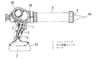
本発明を、添付図面に示す実施形態に基づいて説明する。図1は、本発明の一実施形態の電動工具の側面図であり、図2はこの電動工具の回路図である。 The present invention will be described based on embodiments shown in the accompanying drawings. FIG. 1 is a side view of a power tool according to an embodiment of the present invention, and FIG. 2 is a circuit diagram of the power tool.
本実施形態の電動工具は、メインスイッチ1と出力調整スイッチ2を備えた可搬式のシーリングガン50である。このシーリングガン50では、工具の駆動源であるモータ3を筒型の本体部10内に収容している。この本体部10から径方向外側にむけて延設されるハンドル部11に、トリガスイッチから成るメインスイッチ1と、速度調整ダイヤルから成る出力調整スイッチ2を備えている。
The electric power tool of the present embodiment is a
本体部10には、先端にノズル4を有する円筒状のシリンダ5を装着している。このシリンダ5内には棒状のロッド(図示せず)が収容されており、ロッドの先端には、シリンダ5の内周面に摺接する押圧部材(図示せず)を固定させている。ロッドは、本体部10内のモータ3の動力によって軸方向にスライド移動され、ロッド先端の押圧部材によって、シリンダ5内のシーリング剤をノズル4先端の吐出孔4aから押し出していく。
A
ハンドル部11の先端には、電池パック12が着脱自在に装着される。この電池パック12内には、シーリングガン50の電源部である二次電池7が収容されている。二次電池7は、シーリングガン50のモータ3や制御手段6に対して、電力を供給する。この制御手段6は、メインスイッチ1や出力調整スイッチ2からの入力に基づいてモータ3の回転を制御する。
A
図2の回路図に示すように、二次電池7からモータ3に電力を供給する回路中には、FETのスイッチング素子から成るスイッチ手段8と、電流検出抵抗から成る電流検出手段9とを、モータ3と直列に備えている。制御手段6は、スイッチ手段8を介してモータ3への電力供給を制御し、また、電流検出手段9の両端電圧に基づいてモータ3に流れる電流値を検出する。
As shown in the circuit diagram of FIG. 2, in the circuit for supplying power from the secondary battery 7 to the
上記構成を具備するシーリングガン50において、一定量を超えてメインスイッチ1を引き込み操作すると、モータ3への電力供給がオンになる。このメインスイッチ1の引き込みを開放すると、モータ3への電力供給はオフになる。制御手段6は、出力調整スイッチ2の回転位置に基づいて決定される電圧値に応じてオンデューティを変化させるPWM制御によって、スイッチ手段8を駆動させる。これにより、モータ3の回転数が制御される。
In the
また、制御手段6は、電流検出手段9を用いてモータ3の電流値を検出し、この検出結果が所定の閾値を越えた場合に、スイッチ手段8をオフにすることで、メインスイッチ1を引き込んだ状態であってもモータ3を強制停止させる。ここでの閾値は、出力調整スイッチ2のダイヤル回転位置(即ち、モータ出力の設定値)に応じて変化する。
Further, the control means 6 detects the current value of the
モータ3が強制停止状態に移行した後、この強制停止状態を解除して作業を再開するには、2通りの手段が用いられる。
After the
1つの手段は、メインスイッチ1の引き込みを開放する手段である。モータ3が強制停止状態にあるときにメインスイッチ1がオフになると、制御手段6は信号変化によってこれを検知し、モータ3の強制停止状態を速やかに解除する。ここでメインスイッチ1を引き込むと、その引き込み量が一定量を超えた時点からモータ3は再び回転を始める。
One means is a means for releasing the
もう1つの手段は、出力調整スイッチ2を動作させる手段である。モータ3が強制停止状態にあるときに出力調整スイッチ2が所定量を超えて回転動作されると、制御手段6は信号変化によってこれを検知し、モータ3の強制停止状態を解除する。このとき、メインスイッチ1は引き込み状態のままにあるので、モータ3の回転は速やかに再開される。
Another means is a means for operating the
なお、モータ3が強制停止されてから所定時間を経過した後は、この出力調整スイッチ2を用いた手段によっては強制停止状態から復帰されず、メインスイッチ1を用いた手段によってのみ復帰されるように設けている。
It should be noted that after a predetermined time has elapsed since the
言い換えれば、制御手段6は、モータ3の強制停止状態を解除するための解除条件として、第一の解除条件と第二の解除条件を有し、一方の解除条件を満たせばスイッチ手段8のオフを解除する。この第一の解除条件が、強制停止状態にあるときにメインスイッチ1の引き込みが開放される、という条件である。そして、第二の解除条件が、モータ3が強制停止状態となってから所定時間以内に出力調整スイッチ2が所定量を超えて動作される、という条件である。
In other words, the control means 6 has a first release condition and a second release condition as release conditions for releasing the forced stop state of the
更に、この制御手段6においては、出力調整スイッチ2を動作させて強制停止状態から復帰した後は、復帰後の一定期間の間、検出電流の閾値をこれよりも大きな新たな閾値に変更するように設けている。
Further, in this control means 6, after the
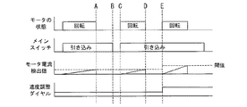
図3には、このシーリングガン50での各信号と動作の一例を示している。この例の場合、図中のA点にて、モータ3を流れる電流が過負荷保護用の閾値に達し、メインスイッチ1を引き込んだ状態のまま、制御手段6によってモータ3が強制停止されている。次いで、図中B点にて、メインスイッチ1の引き込みが開放され、これを検知した制御手段6によってモータ3の強制停止は解除され、図中C点にてメインスイッチ1が引き込まれたタイミングで、モータ3は再度回転を始めている。
FIG. 3 shows an example of each signal and operation in the
図中D点では、モータ3を流れる電流が再び閾値に達し、メインスイッチ1を引き込んだ状態のまま、制御手段6によってモータ3が強制停止されている。次いで、図中E点では、メインスイッチ1が引き込まれたまま、出力調整スイッチ(速度調整ダイヤル)2が動作され、これを検知した制御手段6によってモータ3の強制停止が解除され、速やかに回転を再開している。そして、ここでの強制停止の解除に伴い、電流の閾値は更に高い別の閾値に変更されている。
At point D in the figure, the current flowing through the
以上説明したように、本発明の一実施形態の電動工具(シーリングガン50)は、工具の駆動源であるモータ3と、引き込み操作によりモータ3への電力供給をオンにするメインスイッチ1と、モータ3に流れる電流値を検出する電流検出手段9と、モータ3の回転出力を調整する出力調整スイッチ2と、電流検出手段9での検出結果が所定の閾値を超えた場合にモータ3を強制停止させる制御手段6とを具備する。制御手段6は、強制停止状態にあるときにメインスイッチ1の引き込みが開放されるという第一の解除条件と、強制停止状態にあるときに出力調整スイッチ2が動作されるという第二の解除条件とを有し、第一又は第二の解除条件を満たしたときに強制停止状態を解除する。
As described above, the electric tool (sealing gun 50) according to the embodiment of the present invention includes the
これにより、使用者は、モータ3が強制停止されたときに、メインスイッチ1を開放することで強制停止状態から復帰させるか、或いは、メインスイッチ1を引き込んだまま出力調整スイッチ2を動作させることで強制停止状態から復帰させるかを、状況に応じて選択することができる。特に、シーリングガン50での作業のような、過電流保護のための強制停止が比較的頻繁に行われる作業の場合には、メインスイッチ1は引き込んだままで作業を継続できることにより、作業能率が大幅に向上する。
Thereby, when the
また、前記第二の解除条件は、強制停止状態にあるときに出力調整スイッチ2が所定量を超えて動作される、というものである。
Further, the second release condition is that the
これによると、強制停止状態を解除するためには、所定量を超えて出力調整スイッチ2を動作させる必要があるので、使用者が意図しないタイミングで強制停止状態から復帰するといった事態が抑えられる。
According to this, in order to cancel the forced stop state, it is necessary to operate the
また、前記第二の解除条件は、モータ3が強制停止状態となってから所定時間以内に出力調整スイッチ2が動作される、というものである。
Further, the second release condition is that the
これによると、連続作業を行わない場合には、復帰手段をメインスイッチ1のみにすることができる。したがって、不意に出力調整スイッチ2を動作させて強制停止状態から復帰するという事態が抑制される。
According to this, when continuous work is not performed, the return means can be the
また、制御手段6は、前記第二の解除条件を満たして強制停止状態を解除した後は、閾値をこれよりも高い別の閾値に変更するものである。 Moreover, after satisfy | filling said 2nd cancellation | release condition and canceling a forced stop state, the control means 6 changes a threshold value into another threshold value higher than this.
これによると、連続作業を行うような場合に、モータ3の強制停止が多発することを抑えることができ、作業効率が向上する。
According to this, when continuous work is performed, it is possible to suppress frequent forced stop of the
以上、本発明を添付図面に示す実施形態に基づいて説明したが、本発明は前記実施形態に限定されるものではなく、本発明の意図する範囲内であれば、適宜の設計変更を行うことが可能である。 Although the present invention has been described based on the embodiments shown in the accompanying drawings, the present invention is not limited to the above-described embodiments, and appropriate design changes may be made within the intended scope of the present invention. Is possible.
1 メインスイッチ
2 出力調整スイッチ
3 モータ
6 制御手段
9 電流検出手段
1
Claims (4)
The said control means changes the said threshold value into another threshold value higher than this, after satisfy | filling said 2nd cancellation | release conditions and canceling | releases the said forced stop state, The 1-3 characterized by the above-mentioned. The power tool according to any one of the above.
Priority Applications (4)
| Application Number | Priority Date | Filing Date | Title |
|---|---|---|---|
| JP2011063659A JP5799221B2 (en) | 2011-03-23 | 2011-03-23 | Electric tool |
| EP12760058.3A EP2689896B1 (en) | 2011-03-23 | 2012-02-17 | Electric tool |
| CN201280014528.3A CN103429394B (en) | 2011-03-23 | 2012-02-17 | Electric tool |
| PCT/JP2012/053789 WO2012127950A1 (en) | 2011-03-23 | 2012-02-17 | Electric tool |
Applications Claiming Priority (1)
| Application Number | Priority Date | Filing Date | Title |
|---|---|---|---|
| JP2011063659A JP5799221B2 (en) | 2011-03-23 | 2011-03-23 | Electric tool |
Publications (2)
| Publication Number | Publication Date |
|---|---|
| JP2012196746A true JP2012196746A (en) | 2012-10-18 |
| JP5799221B2 JP5799221B2 (en) | 2015-10-21 |
Family
ID=46879113
Family Applications (1)
| Application Number | Title | Priority Date | Filing Date |
|---|---|---|---|
| JP2011063659A Active JP5799221B2 (en) | 2011-03-23 | 2011-03-23 | Electric tool |
Country Status (4)
| Country | Link |
|---|---|
| EP (1) | EP2689896B1 (en) |
| JP (1) | JP5799221B2 (en) |
| CN (1) | CN103429394B (en) |
| WO (1) | WO2012127950A1 (en) |
Cited By (2)
| Publication number | Priority date | Publication date | Assignee | Title |
|---|---|---|---|---|
| JP2015013327A (en) * | 2013-07-03 | 2015-01-22 | 株式会社マキタ | Power tool |
| WO2022014299A1 (en) * | 2020-07-15 | 2022-01-20 | 工機ホールディングス株式会社 | Work machine and perforation method |
Families Citing this family (1)
| Publication number | Priority date | Publication date | Assignee | Title |
|---|---|---|---|---|
| CN108459519B (en) * | 2017-02-22 | 2021-04-06 | 苏州宝时得电动工具有限公司 | Electric wrench control method and device |
Citations (5)
| Publication number | Priority date | Publication date | Assignee | Title |
|---|---|---|---|---|
| JPS63103623A (en) * | 1986-10-18 | 1988-05-09 | 松下電工株式会社 | Motor-driven machine |
| JPH0799721A (en) * | 1993-09-28 | 1995-04-11 | Makita Corp | Overload preventive circuit for dc motor |
| JP2001252602A (en) * | 2000-03-09 | 2001-09-18 | Ire:Kk | Power tool |
| US20070069672A1 (en) * | 2000-12-06 | 2007-03-29 | Glasgow Kevin L | Power tool and motor controller |
| WO2007067352A1 (en) * | 2005-12-09 | 2007-06-14 | Temple University - Of The Commonwealth System Of Higher Education | Mixer |
Family Cites Families (3)
| Publication number | Priority date | Publication date | Assignee | Title |
|---|---|---|---|---|
| JP5122750B2 (en) * | 2006-02-23 | 2013-01-16 | パナソニック株式会社 | Electric tool |
| US8129955B2 (en) * | 2007-07-13 | 2012-03-06 | Black & Decker Inc. | Reset mechanism for a battery pack |
| CN101714647B (en) * | 2008-10-08 | 2012-11-28 | 株式会社牧田 | Battery pack for power tool, and power tool |
-
2011
- 2011-03-23 JP JP2011063659A patent/JP5799221B2/en active Active
-
2012
- 2012-02-17 CN CN201280014528.3A patent/CN103429394B/en not_active Expired - Fee Related
- 2012-02-17 EP EP12760058.3A patent/EP2689896B1/en active Active
- 2012-02-17 WO PCT/JP2012/053789 patent/WO2012127950A1/en unknown
Patent Citations (5)
| Publication number | Priority date | Publication date | Assignee | Title |
|---|---|---|---|---|
| JPS63103623A (en) * | 1986-10-18 | 1988-05-09 | 松下電工株式会社 | Motor-driven machine |
| JPH0799721A (en) * | 1993-09-28 | 1995-04-11 | Makita Corp | Overload preventive circuit for dc motor |
| JP2001252602A (en) * | 2000-03-09 | 2001-09-18 | Ire:Kk | Power tool |
| US20070069672A1 (en) * | 2000-12-06 | 2007-03-29 | Glasgow Kevin L | Power tool and motor controller |
| WO2007067352A1 (en) * | 2005-12-09 | 2007-06-14 | Temple University - Of The Commonwealth System Of Higher Education | Mixer |
Cited By (2)
| Publication number | Priority date | Publication date | Assignee | Title |
|---|---|---|---|---|
| JP2015013327A (en) * | 2013-07-03 | 2015-01-22 | 株式会社マキタ | Power tool |
| WO2022014299A1 (en) * | 2020-07-15 | 2022-01-20 | 工機ホールディングス株式会社 | Work machine and perforation method |
Also Published As
| Publication number | Publication date |
|---|---|
| EP2689896B1 (en) | 2021-03-31 |
| JP5799221B2 (en) | 2015-10-21 |
| EP2689896A4 (en) | 2015-10-14 |
| WO2012127950A1 (en) | 2012-09-27 |
| CN103429394B (en) | 2015-05-13 |
| CN103429394A (en) | 2013-12-04 |
| EP2689896A1 (en) | 2014-01-29 |
Similar Documents
| Publication | Publication Date | Title |
|---|---|---|
| EP2329922B1 (en) | Rotary tool having a feedback control function | |
| JP4359855B2 (en) | Solenoid valve drive circuit and solenoid valve | |
| WO2011024479A3 (en) | Electric operating machine | |
| JP5914841B2 (en) | Electric tool | |
| EP2853353A2 (en) | Electric power tool | |
| JP2017042839A (en) | Rotary impact tool | |
| WO2009016789A1 (en) | Independent power supply system | |
| EP1967305A4 (en) | Portable drilling machine | |
| JP5799221B2 (en) | Electric tool | |
| US7750587B2 (en) | Method of controlling a motor of a battery-operated power tool | |
| JP2009153960A5 (en) | ||
| US11533841B2 (en) | Electric working machine and method for controlling motor of electric working machine | |
| JP5834240B2 (en) | Electric tool | |
| EP2418762A3 (en) | Switching mode power supply and method of controlling the same | |
| WO2013136673A1 (en) | Electric tool | |
| JP2015188997A (en) | Electric tool | |
| RU2008144296A (en) | ELECTRIC HAND MACHINE WITH SHUT-OFF DELAY DEVICE | |
| WO2013024090A3 (en) | Operation of an illuminant at an autonomous energy store | |
| JP2005204365A (en) | Battery pack | |
| JP5520177B2 (en) | Battery powered power tool | |
| DE102012107275A8 (en) | Motor control device | |
| JP5695166B2 (en) | Power tools | |
| JP2011229279A5 (en) | ||
| JP2009233783A (en) | Motor drive controller for driving power tool | |
| JP2009268244A5 (en) |
Legal Events
| Date | Code | Title | Description |
|---|---|---|---|
| A711 | Notification of change in applicant |
Free format text: JAPANESE INTERMEDIATE CODE: A712 Effective date: 20130513 |
|
| A621 | Written request for application examination |
Free format text: JAPANESE INTERMEDIATE CODE: A621 Effective date: 20140110 |
|
| A711 | Notification of change in applicant |
Free format text: JAPANESE INTERMEDIATE CODE: A711 Effective date: 20141008 |
|
| A131 | Notification of reasons for refusal |
Free format text: JAPANESE INTERMEDIATE CODE: A131 Effective date: 20141111 |
|
| A521 | Request for written amendment filed |
Free format text: JAPANESE INTERMEDIATE CODE: A523 Effective date: 20150113 |
|
| TRDD | Decision of grant or rejection written | ||
| A01 | Written decision to grant a patent or to grant a registration (utility model) |
Free format text: JAPANESE INTERMEDIATE CODE: A01 Effective date: 20150303 |
|
| A61 | First payment of annual fees (during grant procedure) |
Free format text: JAPANESE INTERMEDIATE CODE: A61 Effective date: 20150327 |
|
| R151 | Written notification of patent or utility model registration |
Ref document number: 5799221 Country of ref document: JP Free format text: JAPANESE INTERMEDIATE CODE: R151 |