JP2012196327A - Axis alignment method and x-ray imaging system - Google Patents
Axis alignment method and x-ray imaging system Download PDFInfo
- Publication number
- JP2012196327A JP2012196327A JP2011062633A JP2011062633A JP2012196327A JP 2012196327 A JP2012196327 A JP 2012196327A JP 2011062633 A JP2011062633 A JP 2011062633A JP 2011062633 A JP2011062633 A JP 2011062633A JP 2012196327 A JP2012196327 A JP 2012196327A
- Authority
- JP
- Japan
- Prior art keywords
- ray
- electron beam
- axis
- center
- imaging apparatus
- Prior art date
- Legal status (The legal status is an assumption and is not a legal conclusion. Google has not performed a legal analysis and makes no representation as to the accuracy of the status listed.)
- Withdrawn
Links
- 238000003384 imaging method Methods 0.000 title claims abstract description 51
- 238000000034 method Methods 0.000 title claims abstract description 25
- 238000010894 electron beam technology Methods 0.000 claims description 74
- 238000001514 detection method Methods 0.000 claims description 63
- 239000003550 marker Substances 0.000 claims description 49
- 230000001678 irradiating effect Effects 0.000 claims description 4
- 238000006243 chemical reaction Methods 0.000 description 8
- 238000010586 diagram Methods 0.000 description 7
- 238000009826 distribution Methods 0.000 description 4
- 239000011347 resin Substances 0.000 description 2
- 229920005989 resin Polymers 0.000 description 2
- 238000012790 confirmation Methods 0.000 description 1
- 238000001816 cooling Methods 0.000 description 1
- 230000003247 decreasing effect Effects 0.000 description 1
- 230000001066 destructive effect Effects 0.000 description 1
- 230000005684 electric field Effects 0.000 description 1
- 238000002594 fluoroscopy Methods 0.000 description 1
- 238000007689 inspection Methods 0.000 description 1
- 238000009434 installation Methods 0.000 description 1
- 239000004973 liquid crystal related substance Substances 0.000 description 1
- 238000004519 manufacturing process Methods 0.000 description 1
- 238000003860 storage Methods 0.000 description 1
- WFKWXMTUELFFGS-UHFFFAOYSA-N tungsten Chemical compound [W] WFKWXMTUELFFGS-UHFFFAOYSA-N 0.000 description 1
- 229910052721 tungsten Inorganic materials 0.000 description 1
- 239000010937 tungsten Substances 0.000 description 1
Images


Abstract
Description
本発明は、X線検出器の検出面中心にX線軸を位置合わせする軸合わせ方法、およびX線撮影装置に関する。 The present invention relates to an axis alignment method for aligning an X-ray axis with the center of a detection surface of an X-ray detector, and an X-ray imaging apparatus.
X線撮影装置は、被検体にX線を照射するX線管と、このX線管の照射口に取り付けられて照射させたX線の照射野を調整するコリメータと、被検体を透過したX線を検出するX線検出器とを備えている。これらコリメータを含むX線管とX線検出器は、例えば、C字形の支持アーム(以下「C字形アーム」と称する)の両端に取り付けられて支持される。X線撮影装置は、X線検出器で検出されたX線の強度分布に応じたX線検出信号に基づいてX線画像を取得している。 An X-ray imaging apparatus includes an X-ray tube that irradiates a subject with X-rays, a collimator that is attached to an irradiation port of the X-ray tube and adjusts an irradiation field of the X-rays irradiated, and X that has passed through the subject And an X-ray detector for detecting a line. The X-ray tube and the X-ray detector including these collimators are attached and supported at both ends of, for example, a C-shaped support arm (hereinafter referred to as “C-shaped arm”). The X-ray imaging apparatus acquires an X-ray image based on an X-ray detection signal corresponding to an X-ray intensity distribution detected by an X-ray detector.
また、X線撮影装置に用いられるX線管としては、例えば、陽極が外囲器と一体となって回転する外囲器回転型のX線管がある。このX線管は、X線管本体(外囲器)内の軸中心に設けられた陰極の電子源から発生された電子ビームを、X線管本体の外に設けられた磁場発生器で集束、偏向させて、陽極のターゲットディスク上の所定位置に焦点を形成し、X線を発生させている(例えば、特許文献1参照)。 Moreover, as an X-ray tube used for an X-ray imaging apparatus, for example, there is an envelope rotation type X-ray tube in which an anode rotates integrally with an envelope. In this X-ray tube, an electron beam generated from a cathode electron source provided at the center of an axis in the X-ray tube main body (envelope) is focused by a magnetic field generator provided outside the X-ray tube main body. The focus is formed at a predetermined position on the target disk of the anode and X-rays are generated (see, for example, Patent Document 1).
従来のX線撮影装置は、その据付(組立)時にX線管、コリメータおよびX線検出器をC字形アームに取り付けることが多い。このとき、組立時の部材間での寸法の遊びによる位置ズレや製造加工精度などを補うために、X線管から照射されたX線の中心軸であるX線軸とX線検出器の検出面の中心とを位置合わせする軸合わせを行っている。作業者は、実際にX線を照射して、透視画像を見ながら、X線管やコリメータなどを手で支えるなどして移動させて軸合わせを行い、固定している。そのため、作業者は被ばくし、また、軸合わせのための工数がかかるなど、作業者の負担となっている。 Conventional X-ray imaging apparatuses often have an X-ray tube, a collimator, and an X-ray detector attached to a C-shaped arm during installation (assembly). At this time, in order to compensate for positional deviation due to dimensional play between members during assembly, manufacturing processing accuracy, etc., the X-ray axis that is the central axis of the X-rays emitted from the X-ray tube and the detection surface of the X-ray detector The axis is aligned with the center of the center. The operator actually irradiates X-rays and moves the X-ray tube, collimator, and the like while supporting the X-ray tube and collimator while moving the X-ray tube and collimator. For this reason, the operator is exposed, and the labor for the alignment is increased.
本発明は、このような事情に鑑みてなされたものであって、作業者の負担を軽減させることが可能な軸合わせ方法およびX線撮影装置を提供することを目的とする。 The present invention has been made in view of such circumstances, and an object thereof is to provide an axis alignment method and an X-ray imaging apparatus capable of reducing the burden on an operator.
本発明は、このような目的を達成するために、次のような構成をとる。
すなわち、本発明に係る軸合わせ方法は、電子ビームを発生させる陰極と前記陰極からの電子ビームを偏向させる電子ビーム偏向部と前記電子ビーム偏向部で偏向された電子ビームの衝突によりX線を発生させる陽極とを有するX線を照射するX線管と、前記X線管から照射されたX線を検出するX線検出器とを備えたX線撮影装置におけるX線検出器の検出面中心に照射されたX線の中心軸であるX線軸を位置合わせする軸合わせ方法であって、前記X線検出器の検出面中心に対するX線軸の位置ズレ情報に基づき、前記電子ビーム偏向部の電子ビームの偏向を調整し、前記X線検出器の検出面中央にX線軸を位置合わせするものである。
In order to achieve such an object, the present invention has the following configuration.
That is, the axial alignment method according to the present invention generates X-rays by collision of a cathode for generating an electron beam, an electron beam deflecting unit for deflecting the electron beam from the cathode, and an electron beam deflected by the electron beam deflecting unit. In the center of the detection surface of the X-ray detector in an X-ray imaging apparatus comprising an X-ray tube for irradiating X-rays having an anode to be irradiated and an X-ray detector for detecting X-rays irradiated from the X-ray tube An alignment method for aligning an X-ray axis that is a central axis of irradiated X-rays, wherein the electron beam of the electron beam deflecting unit is based on positional deviation information of the X-ray axis with respect to a detection surface center of the X-ray detector. The X-ray axis is aligned with the center of the detection surface of the X-ray detector.
本発明に係る軸合わせ方法によれば、X線管の電子ビーム偏向部は、陰極から照射された電子ビームを偏向させて陽極の所定の位置に当てて、X線を発生させている。その電子ビーム偏向部を操作することにより、電子ビームが衝突する陽極の焦点位置が移動する。このように、X線を発生する焦点位置が移動することを利用して、X線管等の取付時におけるX線検出器の検出面中心に照射されたX線の中心軸であるX線軸を位置合わせする軸合わせを行う。すなわち、X線検出器の検出面中心に対するX線軸の位置ズレ情報に基づき、電子ビーム偏向部の電子ビームの偏向を調整し、X線検出器の検出面中央にX線軸を位置合わせする。したがって、軸合わせを、例えばX線が遮蔽された装置から離れた場所から操作することができるので、X線の被ばくを軽減することができる。また、電子ビーム偏向部で電子ビームの偏向を調整することにより軸合わせを容易に行うことができるので、工数を抑えることができる。よって、作業者の負担を軽減させることができる。 According to the axis alignment method of the present invention, the electron beam deflecting unit of the X-ray tube deflects the electron beam irradiated from the cathode and applies it to a predetermined position of the anode to generate X-rays. By operating the electron beam deflection unit, the focal position of the anode where the electron beam collides moves. In this way, the X-ray axis that is the central axis of the X-ray irradiated to the center of the detection surface of the X-ray detector when the X-ray tube or the like is attached is utilized by using the movement of the focal position for generating the X-ray. Align the axis to be aligned. That is, based on positional deviation information of the X-ray axis with respect to the center of the detection surface of the X-ray detector, the deflection of the electron beam of the electron beam deflecting unit is adjusted, and the X-ray axis is aligned with the center of the detection surface of the X-ray detector. Therefore, since the axis alignment can be operated, for example, from a place away from the device where X-rays are shielded, X-ray exposure can be reduced. Further, since the axis alignment can be easily performed by adjusting the deflection of the electron beam by the electron beam deflecting unit, the number of man-hours can be reduced. Therefore, the burden on the operator can be reduced.
また、本発明に係るX線撮影装置は、電子ビームを発生させる陰極と、前記陰極からの電子ビームを偏向させる電子ビーム偏向部と、前記電子ビーム偏向部で偏向された電子ビームの衝突によりX線を発生させる陽極とを有するX線を照射するX線管と、前記X線管から照射されたX線を検出するX線検出器と、前記X線検出器の検出面中心に対する、照射されたX線の中心軸であるX線軸の位置ズレ情報に基づき、前記電子ビーム偏向部の電子ビームの偏向を調整し、前記X線検出器の検出面中央にX線軸を位置合わせする偏向調整制御部と、を備えていることを特徴とするものである。 The X-ray imaging apparatus according to the present invention includes a cathode that generates an electron beam, an electron beam deflecting unit that deflects the electron beam from the cathode, and an electron beam deflected by the electron beam deflecting unit. An X-ray tube for irradiating X-rays having an anode for generating a line, an X-ray detector for detecting X-rays emitted from the X-ray tube, and a center of a detection surface of the X-ray detector. Deflection adjustment control for adjusting the deflection of the electron beam of the electron beam deflection unit based on the positional deviation information of the X-ray axis, which is the central axis of the X-ray, and aligning the X-ray axis with the center of the detection surface of the X-ray detector And a section.
本発明に係るX線撮影装置によれば、X線管の電子ビーム偏向部は、陰極から照射された電子ビームを偏向させて陽極の所定の位置に当てて、X線を発生させている。偏向調整制御部により電子ビーム偏向部を操作することにより、電子ビームが衝突する陽極の焦点位置が移動する。このように、X線を発生する焦点位置が移動することを利用して、X線管等の取付時におけるX線検出器の検出面中心に照射されたX線の中心軸であるX線軸を位置合わせする軸合わせを行う。すなわち、偏向調整制御部は、X線検出器の検出面中心に対するX線軸の位置ズレ情報に基づき、電子ビーム偏向部の電子ビームの偏向を調整し、X線検出器の検出面中央にX線軸を位置合わせする。したがって、軸合わせを、例えばX線が遮蔽された装置から離れた場所から操作することができるので、X線の被ばくを軽減することができる。また、電子ビーム偏向部で電子ビームの偏向を調整することにより軸合わせを容易に行うことができるので、工数を抑えることができる。よって、作業者の負担を軽減させることができる。 According to the X-ray imaging apparatus of the present invention, the electron beam deflecting unit of the X-ray tube deflects the electron beam irradiated from the cathode and applies it to a predetermined position of the anode to generate X-rays. By operating the electron beam deflection unit by the deflection adjustment control unit, the focal position of the anode where the electron beam collides moves. In this way, the X-ray axis that is the central axis of the X-ray irradiated to the center of the detection surface of the X-ray detector when the X-ray tube or the like is attached is utilized by using the movement of the focal position for generating the X-ray. Align the axis to be aligned. In other words, the deflection adjustment control unit adjusts the deflection of the electron beam of the electron beam deflection unit based on the positional deviation information of the X-ray axis with respect to the center of the detection surface of the X-ray detector, and sets the X-ray axis at the center of the detection surface of the X-ray detector. Align. Therefore, since the axis alignment can be operated, for example, from a place away from the device where X-rays are shielded, X-ray exposure can be reduced. Further, since the axis alignment can be easily performed by adjusting the deflection of the electron beam by the electron beam deflecting unit, the number of man-hours can be reduced. Therefore, the burden on the operator can be reduced.
また、本発明に係るX線撮影装置は、前記X線検出器から取得した画像に基づいて前記X線検出器の検出面中心に対するX線軸の位置ズレ情報を算出する位置ズレ情報算出部を備え、前記偏向調整制御部は、算出された位置ズレ情報に基づいて前記X線検出器の検出面中心にX線軸を位置合わせすることが好ましい。X線検出器から取得した画像に基づいて位置ズレ情報算出部でX線検出器の検出面の中心に対する位置ズレ情報を算出する。この位置ズレ情報に基づいて、偏向調整制御部は、電子ビーム偏向部を操作することで焦点位置を移動させてX線検出器の検出面中心にX線軸を位置合わせする。すなわち、軸合わせを自動で行うことができるので、軸合わせを容易に行うことができ、さらに工数を抑えることができる。 The X-ray imaging apparatus according to the present invention further includes a position shift information calculation unit that calculates position shift information of the X-ray axis with respect to the center of the detection surface of the X-ray detector based on an image acquired from the X-ray detector. The deflection adjustment control unit preferably aligns the X-ray axis with the center of the detection surface of the X-ray detector based on the calculated positional deviation information. Based on the image acquired from the X-ray detector, the positional shift information calculation unit calculates positional shift information with respect to the center of the detection surface of the X-ray detector. Based on this positional deviation information, the deflection adjustment control unit moves the focal position by operating the electron beam deflection unit to align the X-ray axis with the center of the detection surface of the X-ray detector. That is, since the axis alignment can be automatically performed, the axis alignment can be easily performed, and the man-hour can be further reduced.
また、本発明に係るX線撮影装置は、前記X線管のX線照射側に取り付けられ、X線の照射野を調整するコリメータを備えていることが好ましい。従来のように、コリメータを手で支えるなどして移動させながら軸合わせを行い、固定していたが、コリメータを移動させずに、偏向調整制御部により、X線検出器の検出面中心に対するX線軸の位置ズレ情報に基づき、電子ビーム偏向部の電子ビームの偏向を調整し、軸合わせすることができる。 The X-ray imaging apparatus according to the present invention preferably includes a collimator that is attached to the X-ray irradiation side of the X-ray tube and adjusts the X-ray irradiation field. As in the past, the axis was aligned and fixed while moving the collimator by hand or the like, but the X axis with respect to the center of the detection surface of the X-ray detector was detected by the deflection adjustment control unit without moving the collimator. Based on the positional deviation information of the linear axis, the electron beam deflection of the electron beam deflecting unit can be adjusted and aligned.
また、本発明に係るX線撮影装置は、X線照射側に取り付けられ、X線を遮蔽するマーカーを備えていることが好ましい。X線管からX線が照射されるとマーカーがX線を遮蔽する。そのため、X線検出器で取得された画像のマーカーの位置に基づいて、X線検出器の検出面中心にX線軸を移動させることを容易に行うことができる。 The X-ray imaging apparatus according to the present invention preferably includes a marker that is attached to the X-ray irradiation side and shields X-rays. When the X-ray is irradiated from the X-ray tube, the marker shields the X-ray. Therefore, it is possible to easily move the X-ray axis to the center of the detection surface of the X-ray detector based on the marker position of the image acquired by the X-ray detector.
また、本発明に係るX線撮影装置は、前記コリメータの複数枚のリーフにより形成される開口部の中心でかつ、前記複数枚のリーフと同じ高さに取り付けられ、X線を遮蔽するマーカーを備えていることが好ましい。焦点から照射されてマーカーで遮蔽されたX線がX線検出器の検出面に入射される。すなわち、マーカーにより、焦点とマーカーとを結ぶ線およびその延長線で構成される線をX線軸として軸合わせが行われる。しかしながら、マーカーの位置により、コリメータで調整される実際のX線の中心軸とマーカーにより形成されるX線軸とでズレが生じる。このズレを抑えることができる。 In addition, the X-ray imaging apparatus according to the present invention includes a marker that is attached to the center of the opening formed by the plurality of leaves of the collimator and at the same height as the plurality of leaves and shields the X-rays. It is preferable to provide. X-rays irradiated from the focal point and shielded by the marker are incident on the detection surface of the X-ray detector. That is, the alignment is performed by the marker with the line formed by the line connecting the focal point and the marker and the extended line as the X-ray axis. However, there is a deviation between the center axis of the actual X-ray adjusted by the collimator and the X-ray axis formed by the marker depending on the position of the marker. This deviation can be suppressed.
本発明に係る軸合わせ方法およびX線撮影装置によれば、X線管の電子ビーム偏向部は、陰極から照射された電子ビームを偏向させて陽極の所定の位置に当てて、X線を発生させている。その電子ビーム偏向部を操作することにより、電子ビームが衝突する陽極の焦点位置が移動する。このように、X線を発生する焦点位置が移動することを利用して、X線管等の取付時におけるX線検出器の検出面中心に照射されたX線の中心軸であるX線軸を位置合わせする軸合わせを行う。すなわち、X線検出器の検出面中心に対するX線軸の位置ズレ量に基づき、電子ビーム偏向部の電子ビームの偏向を調整し、X線検出器の検出面中央にX線軸を位置合わせする。したがって、軸合わせを、例えばX線が遮蔽された装置から離れた場所から操作することができるので、X線の被ばくを軽減することができる。また、電子ビーム偏向部で電子ビームの偏向を調整することにより軸合わせを容易に行うことができるので、工数を抑えることができる。よって、作業者の負担を軽減させることができる。 According to the axial alignment method and the X-ray imaging apparatus of the present invention, the electron beam deflecting unit of the X-ray tube generates an X-ray by deflecting the electron beam irradiated from the cathode and applying it to a predetermined position of the anode. I am letting. By operating the electron beam deflection unit, the focal position of the anode where the electron beam collides moves. In this way, the X-ray axis that is the central axis of the X-ray irradiated to the center of the detection surface of the X-ray detector when the X-ray tube or the like is attached is utilized by using the movement of the focal position for generating the X-ray. Align the axis to be aligned. That is, the deflection of the electron beam of the electron beam deflecting unit is adjusted based on the amount of positional deviation of the X-ray axis with respect to the center of the detection surface of the X-ray detector, and the X-ray axis is aligned with the center of the detection surface of the X-ray detector. Therefore, since the axis alignment can be operated, for example, from a place away from the device where X-rays are shielded, X-ray exposure can be reduced. Further, since the axis alignment can be easily performed by adjusting the deflection of the electron beam by the electron beam deflecting unit, the number of man-hours can be reduced. Therefore, the burden on the operator can be reduced.
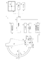
以下、図面を参照して本発明の実施例を説明する。図1は、実施例1に係るX線撮影装置の概略構成を示すブロック図であり、図2は、コリメータの説明に供する図である。図3(a)はX線管の概略側面図であり、図3(b)はX線管の磁場発生器の概略正面図である。 Embodiments of the present invention will be described below with reference to the drawings. FIG. 1 is a block diagram illustrating a schematic configuration of the X-ray imaging apparatus according to the first embodiment, and FIG. 2 is a diagram for explaining a collimator. 3A is a schematic side view of the X-ray tube, and FIG. 3B is a schematic front view of the magnetic field generator of the X-ray tube.
図1を参照する。X線撮影装置1は、X線を照射するX線管3と、X線管3と対向して配置され、X線管3から照射されたX線を検出するX線検出器5と、X線管3の照射側に取り付けられ、X線管3から照射されたX線の照射野を調整するコリメータ7とを備えている。X線管3およびX線検出器5は、C字形アーム9の両端に取り付けられて支持されている。
Please refer to FIG. The
X線管3は、X線管制御部11によりX線照射に必要な制御が実行される。X線管制御部11は、X線管3の管電圧や管電流を発生させる高電圧発生部13を有している。X線管制御部11は、後述する入力部21で設定された管電圧や管電流や照射時間等のX線条件に応じてX線管3からX線を照射させている。
The
X線検出器5は、X線管3から照射されたX線を検出し、X線強度分布に応じた信号であるX線検出信号を出力する。X線検出器5は、フラットパネル型X線検出器(FPD)やイメージインテンシファイア等で構成される。
The
コリメータ7は、図2に示すように、ある方向に鏡像対象に移動して開閉動作を行う一対のリーフ7aと、このリーフ7aと直交する方向に鏡像対象に移動して開閉動作を行う一対のリーフ7bとから構成される。また、各リーフ7a、7bによって、矩形の照射野を調整している。なお、図2では、リーフ7a,7bは、4枚で構成されるが、他の枚数であってもよい。
As shown in FIG. 2, the
図1に戻る。X線検出器5の後段には、画像処理部15が設けられている。画像処理部15は、X線検出器5から出力されたX線検出信号に基づく画像に対して種々の処理を行う。また、X線撮影装置1は、この装置1の各構成を統括的に制御する主制御部17と、画像処理部15で処理された画像を表示する表示部19と、作業者(操作者)が入力設定や各種操作を行う入力部21と、処理された画像を記憶するメモリ部23とを備えている。
Returning to FIG. An
主制御部17は、中央演算処理装置(CPU)などで構成されている。表示部19は、液晶モニタ等で構成される。入力部21は、キーボードやマウスやジョイスティック等で構成される。メモリ部23は、ROM(Read-only Memory)、RAM(Random-Access Memory)またはハードディスク等の記憶媒体で構成される。
The
X線管3の構成を具体的に説明する。X線管3は、外囲器回転型で構成される。X線管3は、図3(a)に示すように、電子ビームを発生させる陰極25と、その陰極25を溝の中に取り付けた円筒電極27と、陰極25から照射された電子ビームを集束・偏向させるために磁場を発生させる磁場発生器29と、その磁場発生器29によって集束・偏向した電子ビームの衝突によりX線を発生させる陽極31と、陰極25、円筒電極27および陽極31等を内部に収容し、陽極31と一体となって回転する外囲器33とを備えている。なお、磁場発生器29は、本発明における電子ビーム偏向部に相当する。
The configuration of the
陰極25は、例えばタングステンで形成されたフィラメントで構成されている。陰極25は、フィラメントなどに代表される熱電子放出型の他に、電界放出型であってもよく特に限定されない。磁場発生器29は、図3(b)に示すように、4つの磁極29aとそれらを支持する多角形(図3(b)では八角形)のヨーク29bとで構成される。ヨーク29bは、図3(a)に示すように、X線管本体である外囲器33の外周部を囲む環状に構成されている。磁極29aにはコイル29cが直接巻かれている。別の構成として、コイル29cはボビン(筒)に巻かれ、そのボビンを磁極29aに差し込むことで、磁極29aにコイル29cを巻いてもよい。なお、図3(b)で磁極29aは4つであるが、他の個数、例えば8つであってもよい。
The
陽極31は外囲器33内部に、外囲器33と一体となって配設されている。陽極31にはターゲット傾斜部31aを設けており、集束、偏向した電子ビームが、高電圧が作る電界により陽極31に向けて加速し、ターゲット傾斜部31aに衝突することでX線を発生させる。外囲器33は真空排気されている。外囲器33の陰極25側には陰極側回転軸35を配設しており、外囲器33の陽極31側には陽極側回転軸37を配設している。両回転軸35,37を回転させることで、陽極31と一体となって外囲器33が回転する。また、外囲器33の外部には、冷却用のオイルあるいは空気などで充填されて、X線窓を有するハウジング(いずれも図示しない)が設けられている。
The
磁場発生器29の各磁極29aに巻かれているコイル29cには、図1に示すように、電源部39からそれぞれに任意の電流が供給される。各磁極29aのコイル29cに供給された電流により、各磁極29aの磁力を強めたり弱めたりすることで、陰極25からの電子ビームの方向を偏向させる。電源部39は、入力部41により、各磁極29aのコイル29cに供給する電流の操作情報(以下適宜、「電流情報」)が入力される。なお、入力部21から各磁極29aのコイル29cに供給する電流情報を入力して電源部39に電流情報を与えるようにしてもよい。
As shown in FIG. 1, an arbitrary current is supplied to each
X線撮影装置1は、X線照射側(X線管3やコリメータ7)に取り付けられ、X線を遮蔽するマーカー43が取り付けられている。マーカー43は、鉛などのX線を遮蔽する物体で構成されている。マーカー43は、コリメータ7の複数枚のリーフ7a,7bにより形成される開口部(絞り)の中心でかつ、複数枚のリーフ7a,7bと同じ高さに取り付けられている。すなわち、X線を発生する焦点とマーカー43とを結ぶ線およびその延長線をX線軸と仮定している。また、例えば、板状の樹脂中に埋められたマーカー43を、リーフ7a,7bに隣接して配置するようにしたり、リーフ7a,7bの間に配置したりするようにしてもよい。マーカー43は、軸合わせの時のみ取り付けられる。
The
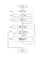
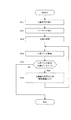
次に、図4を参照して、本実施例のX線撮影装置1の動作、特に軸合わせ方法をフローチャートに沿って説明する。
Next, with reference to FIG. 4, the operation of the
〔ステップS01〕X線管等の取付
X線撮影装置1を組み立てる。C字形アーム9は、そのC字形の曲がりに沿ってC字形アーム9をスライド回転(符号p)させたり、水平軸haを中心にC字形アーム9を回転(符号q)させたりする回転機構(図示しない)に支持されている。そのC字形アーム9にX線管3、X線検出器5およびコリメータ7を所定の順番で取り付ける。取付は、ボルトや、位置決めのための突起、穴および切り欠き部等により、予め設定された位置に取り付けられる。そのため、ある程度の精度を持ってX線管3、X線検出器5およびコリメータ7が取り付けられる。この状態において、X線管3から照射されたX線の中心軸であるX線軸とX線検出器5の検出面5a中心とを位置合わせする軸合わせを行う。
[Step S01] Attachment of X-ray tube or the like The
〔ステップS02〕マーカーの取付
マーカー43は、コリメータ7の複数枚のリーフ7a,7bにより形成される開口部の中心でかつ、前記複数枚のリーフと同じ高さに取り付けられる。
[Step S02] Attaching Marker The
〔ステップS03〕X線の照射
マーカー43の取り付け後、入力部21で予め入力された管電圧や管電流や照射時間等のX線透視条件に基づき、X線管制御部11の高電圧発生部13から高電圧が発生されてX線管3に供給される。X線管3は、高電圧発生部13からの高電圧に基づき、X線を照射する。
[Step S03] X-ray Irradiation After the
〔ステップS04〕位置ズレの確認
X線管3から照射されたX線は、X線検出器5で検出される。X線検出器5からX線の強度分布に応じてX線検出信号が出力される。このX線検出信号に基づき取得した画像は、画像処理部15により必要な種々の画像処理が行われる。そして、取得した画像は、表示部19に表示される。表示部19の表示画面には、マーカー43が映される(図1)。それにより、作業者は、そのマーカー43が画面の中央に対してどの程度で位置ズレしているかについて確認することができる。
[Step S04] Confirmation of Misalignment X-rays emitted from the
〔ステップS05〕位置ズレの判定
作業者は、マーカー43が表示された表示部19を観察して、マーカー43が表示画面の中央に対して位置ズレを確認する。位置ズレしている場合は、ステップS06に進み、位置ズレが無い場合は、終了する(ENDに進む)。
[Step S05] Judgment of Position Shift The operator observes the
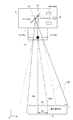
〔ステップS06〕X線軸の位置合わせ(電流情報入力)
図5に示すように、X線検出器5の検出面5a中心に対して、X線軸が位置ズレしているとする。位置ズレしているX線軸を符号XA1で示し、位置ズレ量を符号d1で示す。作業者は、ステップS04において、表示部19に表示されたマーカー43の位置ズレ情報(位置ズレ量、方向)、すなわち、X線検出器5の検出面5a中心に対するX線軸XA1の位置ズレ情報に基づき、磁場発生器29の電子ビームの偏向を調整し、X線検出器5の検出面5a中央にX線軸XA1を位置合わせする。
[Step S06] X-ray axis alignment (current information input)
As shown in FIG. 5, it is assumed that the X-ray axis is displaced with respect to the center of the
具体的には、作業者は、入力部41により、磁場発生器29の各磁極29aのコイル29c(図3)に供給する電流情報を入力する。各磁極29aにより、陰極25から照射された電子ビームが偏向されて、図5に示すように、陽極31に衝突させる焦点位置f1から焦点位置f2に移動する。すると、マーカー43を通るX線軸が、X線軸XA1からX線軸XA2に移動する。これにより、表示部19の表示画面の中央、すなわちX線検出器5の検出面5aにX線軸を位置合わせすることができる。
Specifically, the operator inputs current information to be supplied to the
なお、ステップS04〜ステップS06を繰り返し、ステップS05において、位置ズレが無い場合は、終了する(ENDに進む)。なお、図5では、横方向(X方向)の位置ズレを示すが、奥行き方向(Y方向)の位置ズレする場合も、同様に軸合わせ作業が行われる。 Note that step S04 to step S06 are repeated, and if there is no position shift in step S05, the process ends (proceeds to END). Although FIG. 5 shows a positional shift in the horizontal direction (X direction), the axis alignment operation is similarly performed when the positional shift is in the depth direction (Y direction).
本実施例に係るX線撮影装置1の軸合わせ方法によれば、X線管3の磁場発生器29は、陰極25から照射された電子ビームを偏向させて陽極31の所定の位置に当てて、X線を発生させている。その磁場発生器29を操作することにより、電子ビームが衝突する陽極31の焦点位置が移動する。このように、X線を発生する焦点位置が移動することを利用して、X線管3等の取付時におけるX線検出器5の検出面中心に照射されたX線の中心軸であるX線軸を位置合わせする軸合わせを行う。すなわち、X線検出器5の検出面5a中心に対するX線軸の位置ズレ情報に基づき、磁場発生器29の電子ビームの偏向を調整し、X線検出器5の検出面5a中央にX線軸を位置合わせする。したがって、軸合わせを、例えばX線が遮蔽された装置1から離れた場所から操作することができるので、X線の被ばくを軽減することができる。また、磁場発生器29で電子ビームの偏向を調整することにより軸合わせを容易に行うことができるので、工数を抑えることができる。よって、作業者の負担を軽減させることができる。
According to the axis alignment method of the
また、従来のように、X線管3やコリメータ7等を手で支えるなどして移動させながら軸合わせを行い、固定していたが、X線管3やコリメータ7を移動させずに、X線検出器5の検出面5a中心に対するX線軸の位置ズレ情報に基づき、磁場発生器29の電子ビームの偏向を調整し、軸合わせすることができる。
In addition, as in the prior art, the
また、X線管3からX線が照射されるとマーカー43がX線を遮蔽する。そのため、X線検出器5で取得された画像のマーカー43の位置に基づいて、X線検出器5の検出面5a中心にX線軸を移動させることを容易に行うことができる。
When the
また、マーカー43は、コリメータ7の複数枚のリーフ7a,7bにより形成される開口部の中心でかつ、複数枚のリーフ7a,7bと同じ高さに取り付けられている。すなわち、マーカー43により、焦点とマーカー43とを結ぶ線およびその延長線で構成される線をX線軸として軸合わせが行われる。しかしながら、マーカー43の位置により、コリメータ7で調整される実際のX線の中心軸とマーカー43により形成されるX線軸とでズレが生じる。このズレを抑えることができる。
The
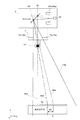
図6を参照して、マーカー43の位置について、具体的に説明する。マーカー43は、例えば、筒状の樹脂中に埋められているものとする。そして、このマーカー43は、図6のように、コリメータ7の照射側の端面に取り付けられている。焦点位置f1からマーカー43を介するX線軸XA1を軸合わせして、焦点位置f3からマーカー43を介するX線軸XA3にする。このとき、焦点位置f3からコリメータ7の各リーフ7a,7bを介して照射されるX線における、実際のX線軸は符号XA4となる。すなわち、マーカー43を介したX線軸XA3と、コリメータ7を介したX線における実際のX線軸XA4とでズレ(符号d2)が生じる。そのため、マーカー43は、リーフ7a,7bとほぼ同じ高さに取り付けられていることが好ましい。リーフ7a,7bにより形成される開口部の中心から外れる場合もズレが生じる。
With reference to FIG. 6, the position of the
次に、図面を参照して本発明の実施例2を説明する。図7は、実施例2に係るX線撮影装置の概略構成を示すブロック図である。なお、上述した実施例と重複する構成については、その説明を省略する。 Next, Embodiment 2 of the present invention will be described with reference to the drawings. FIG. 7 is a block diagram illustrating a schematic configuration of the X-ray imaging apparatus according to the second embodiment. Note that the description of the same configuration as that of the above-described embodiment is omitted.
上述した実施例1は、電源部39を備え、作業者は、表示部19に表示されたマーカー43の位置ズレ情報に基づき、磁場発生器29の各磁極29aのコイル29cに供給する電流情報を入力し、各磁極29aのコイル29cに電流を供給していた。すなわち、作業者が各磁極29aのコイル29cに供給する電流情報を入力して軸合わせを行っていた。実施例2のX線撮影装置50では、電源部39から供給する電流情報を、移動情報(位置ズレ情報)に基づいて電流情報に変換する電流情報変換部51を備えている。
The first embodiment described above includes the
図7を参照する。電流情報変換部51は、入力部21により入力される移動情報に基づいて、磁場発生器29の各磁極29aのコイル29cに供給する電流情報に変換する。この電流情報は、例えば、各磁極29aのコイル29cに供給する電流情報と、X線軸の検出面5a上の移動量との関係から求められる。また、理論上、焦点の移動量から求められ、焦点の移動量は、焦点とマーカー43との距離、マーカー43と検出面5aとの距離、検出面におけるX線軸の移動量(位置ズレ量)等、陽極31のターゲット傾斜部31aを考慮して求められる。電源部39は、電流情報変換部51で変換された電流情報に基づいて、磁場発生器29の各磁極29aのコイル29cに電流を供給する。偏向調整制御部53は、電源部39と電流情報変換部51等から構成される。
Please refer to FIG. The current
次に、図8を参照して、本実施例のX線撮影装置50の動作、特に軸合わせ方法を説明する。ステップS11〜ステップS15は、実施例1のステップS01〜ステップS05と同じであるので、その説明を省略する。
Next, with reference to FIG. 8, the operation of the
〔ステップS16〕X線軸の位置合わせ(移動情報入力)
図5に示すように、X線軸XA1が位置ズレしているとする。作業者は、ステップS14において、表示部19に表示されたマーカー43の位置ズレ量、すなわち、X線検出器5の検出面5a中心に対するX線軸XA1の位置ズレ量に基づき、磁場発生器29の電子ビームの偏向を調整し、X線検出器5の検出面5a中央にX線軸XA1を位置合わせする。
[Step S16] X-ray axis alignment (movement information input)
Assume that the X-ray axis XA1 is misaligned as shown in FIG. In step S <b> 14, the worker determines the position of the
具体的には、作業者は、入力部21から、X線軸を位置合わせする移動情報を入力する。例えば、作業者は、ジョイスティックで操作する。この操作により、予め設定された移動情報が入力される。そして、電流情報変換部51は、移動情報(移動量と方向)に応じた電流情報に変換する。電源部39は、電流情報に基づき、磁場発生器29の各磁極29aのコイル29cにそれぞれ電流を供給する。
Specifically, the operator inputs movement information for aligning the X-ray axis from the
なお、ステップS14〜ステップS16を繰り返し、ステップS15において、位置ズレが無い場合は、終了する(ENDに進む)。 Note that step S14 to step S16 are repeated, and if there is no position shift in step S15, the process ends (proceeds to END).
本実施例に係るX線撮影装置50によれば、X線管3の磁場発生器29は、陰極25から照射された電子ビームを偏向させて陽極31の所定の位置に当てて、X線を発生させている。偏向調整制御部53により磁場発生器29を操作することにより、電子ビームが衝突する陽極31の焦点位置が移動する。このように、X線を発生する焦点位置が移動することを利用して、X線管3等の取付時におけるX線検出器5の検出面5a中心に照射されたX線の中心軸であるX線軸を位置合わせする軸合わせを行う。すなわち、偏向調整制御部53は、X線検出器5の検出面5a中心に対するX線軸の位置ズレ情報に基づき、磁場発生器29の電子ビームの偏向を調整し、X線検出器5の検出面5a中央にX線軸を位置合わせする。したがって、軸合わせを、例えばX線が遮蔽された装置から離れた場所から操作することができるので、X線の被ばくを軽減することができる。また、磁場発生器29で電子ビームの偏向を調整することにより軸合わせを容易に行うことができるので、工数を抑えることができる。よって、作業者の負担を軽減させることができる。
According to the
次に、図面を参照して本発明の実施例3を説明する。図9は、実施例3に係るX線撮影装置の概略構成を示すブロック図である。なお、上述した実施例と重複する構成については、その説明を省略する。
Next,
上述した実施例2は、偏向調整制御部53(電源部39と電流情報変換部51等)を備え、作業者は、表示部19に表示されたマーカー43の位置ズレ情報に基づき、X線軸を位置合わせする移動情報(位置ズレ情報)を入力することで、移動情報に応じた電流情報に変換し、各磁極29aのコイル29cにそれぞれ電流を供給していた。すなわち、作業者が移動情報を入力することで軸合わせを行っていた。実施例3のX線撮影装置60では、移動情報(位置ズレ情報)を、X線検出器5から取得した画像に基づいて算出する位置ズレ情報算出部61を備えている。
The above-described second embodiment includes the deflection adjustment control unit 53 (the
図9を参照する。画像処理部15は、位置ズレ情報算出部61を有する。位置ズレ情報算出部61は、X線検出器5から取得した画像に基づいてX線検出器5の検出面5a中心に対するX線軸の位置ズレ情報を算出する。位置ズレ情報算出部61は、X線検出器5の検出面5a中心、すなわち画像の中心と、画像に含まれるマーカー43の位置との位置ズレ情報(位置ズレ量と方向)を算出する。この位置ズレ情報は偏向調整制御部53に送信される。なお、位置ズレ情報算出部61は、画像処理部15と独立して設けられていてもよい。
Please refer to FIG. The
次に、図10を参照して、本実施例のX線撮影装置60の動作、特に軸合わせ方法を説明する。ステップS21〜ステップS23は、実施例1のステップS01〜ステップS03と同じであるので、その説明を省略する。
Next, with reference to FIG. 10, the operation of the
〔ステップS24〕位置ズレ情報の算出
X線管3から照射されたX線は、X線検出器5で検出される。X線検出器5からX線の強度分布に応じてX線検出信号が出力される。このX線検出信号に基づき取得した画像は、画像処理部15により必要な種々の画像処理が行われる。そして、取得した画像は、表示部19に表示される。表示部19の表示画面には、マーカー43が映される。また、位置ズレ情報算出部61は、X線検出器5から取得した画像に基づいてX線検出器5の検出面5a中心に対するX線軸の位置ズレ情報を算出する。
[Step S24] Calculation of positional deviation information X-rays emitted from the
〔ステップS25〕位置ズレの判定
位置ズレ情報算出部61で算出された位置ズレ情報に基づき、位置ズレの有無を判定する。判定は、例えば、位置ズレ量が予め設定された値以下(未満)の場合に、位置ズレ無しと判定し、位置ズレ量が予め設定された値より大きい(以下)の場合に、位置ズレ有りと判定する。位置ズレしている場合は、ステップS26に進み、位置ズレが無い場合は、終了する(ENDに進む)。
[Step S25] Determination of Position Deviation Based on the position deviation information calculated by the position deviation information calculation unit 61, the presence / absence of position deviation is determined. For example, when the positional deviation amount is equal to or less than a preset value (less than), it is determined that there is no positional deviation, and when the positional deviation amount is greater than a preset value (less than), there is a positional deviation. Is determined. If there is a positional deviation, the process proceeds to step S26, and if there is no positional deviation, the process ends (proceeds to END).
〔ステップS26〕X線軸の位置合わせ(移動情報入力)
図5に示すように、X線軸XA1が位置ズレしているとする。作業者は、入力部21から軸合わせの作業をX線撮影装置60に実行させる。偏向調整制御部53は、算出された位置ズレ情報に基づいてX線検出器5の検出面5a中心にX線軸XA1を位置合わせする。
[Step S26] X-ray axis alignment (movement information input)
Assume that the X-ray axis XA1 is misaligned as shown in FIG. The operator causes the
具体的には、作業者の入力部21からの指示により、X線撮影装置60の位置ズレ情報算出部61は、X線検出器5から取得した画像に基づいてX線検出器5の検出面5a中心に対するX線軸の位置ズレ情報を算出する。電流情報変換部51は、位置ズレ情報(移動情報)に応じた電流情報に変換し、電源部39は、電流情報に基づき、磁場発生器29の各磁極29aのコイル29cにそれぞれ電流を供給する。それにより、表示部19の表示画面の中央、すなわちX線検出器5の検出面5aにX線軸を位置合わせすることができる。
Specifically, according to an instruction from the
なお、ステップS24〜ステップS26を繰り返し、ステップS25において、位置ズレが無い場合は、終了する(ENDに進む)。 Note that step S24 to step S26 are repeated, and if there is no position shift in step S25, the process ends (proceeds to END).
本実施例に係るX線撮影装置60によれば、X線検出器5から取得した画像に基づいて位置ズレ情報算出部61でX線検出器5の検出面5aの中心に対する位置ズレ情報を算出する、この位置ズレ情報に基づいて、偏向調整制御部53は、磁場発生器29を操作することで焦点位置を移動させて、X線検出器5の検出面5a中心にX線軸を位置合わせする。すなわち、軸合わせを自動で行うことができるので、軸合わせを容易に行うことができ、さらに工数を抑えることができる。
According to the
本発明は、上記実施形態に限られることはなく、下記のように変形実施することができる。 The present invention is not limited to the above embodiment, and can be modified as follows.
(1)非破壊検査機器などの工業用装置やX線診断装置などの医用装置にも適用することができる。 (1) The present invention can also be applied to industrial devices such as non-destructive inspection equipment and medical devices such as an X-ray diagnostic device.
(2)上述した各実施例では、外囲器33は、陽極31と一体となって回転するが、これに限定されない。例えば、外囲器33は固定され、陽極31のみ回転するようにしてもよい。
(2) In each of the embodiments described above, the
1,50,60 … X線撮影装置
3 … X線管
5 … X線検出器
7 … コリメータ
15 … 画像処理部
25 … 陰極
29 … 磁場発生器
29a… 磁極
31 … 陽極
39 … 電源部
43 … マーカー
51 … 電流情報変換部
53 … 偏向調整制御部
61 … 位置ズレ情報算出部
DESCRIPTION OF
Claims (6)
前記X線検出器の検出面中心に対するX線軸の位置ズレ情報に基づき、前記電子ビーム偏向部の電子ビームの偏向を調整し、前記X線検出器の検出面中央にX線軸を位置合わせする軸合わせ方法。 X for irradiating X-rays having a cathode for generating an electron beam, an electron beam deflecting unit for deflecting an electron beam from the cathode, and an anode for generating X-rays by collision of the electron beam deflected by the electron beam deflecting unit X, which is the central axis of X-rays irradiated to the center of the detection surface of the X-ray detector in an X-ray imaging apparatus comprising an X-ray detector and an X-ray detector for detecting X-rays irradiated from the X-ray tube An alignment method for aligning linear axes,
An axis that adjusts the deflection of the electron beam of the electron beam deflection unit based on positional deviation information of the X-ray axis with respect to the center of the detection surface of the X-ray detector, and aligns the X-ray axis with the center of the detection surface of the X-ray detector How to match.
前記X線管から照射されたX線を検出するX線検出器と、
前記X線検出器の検出面中心に対する、照射されたX線の中心軸であるX線軸の位置ズレ情報に基づき、前記電子ビーム偏向部の電子ビームの偏向を調整し、前記X線検出器の検出面中央にX線軸を位置合わせする偏向調整制御部と、
を備えていることを特徴とするX線撮影装置。 Irradiating X-rays having a cathode for generating an electron beam, an electron beam deflecting unit for deflecting an electron beam from the cathode, and an anode for generating X-rays by collision of the electron beam deflected by the electron beam deflecting unit An X-ray tube,
An X-ray detector for detecting X-rays emitted from the X-ray tube;
Based on the positional deviation information of the X-ray axis that is the central axis of the irradiated X-ray with respect to the center of the detection surface of the X-ray detector, the deflection of the electron beam of the electron beam deflecting unit is adjusted, and the X-ray detector A deflection adjustment control unit for aligning the X-ray axis with the center of the detection surface;
An X-ray imaging apparatus comprising:
前記X線検出器から取得した画像に基づいて前記X線検出器の検出面中心に対するX線軸の位置ズレ情報を算出する位置ズレ情報算出部を備え、
前記偏向調整制御部は、算出された位置ズレ情報に基づいて前記X線検出器の検出面中心にX線軸を位置合わせすることを特徴とするX線撮影装置。 The X-ray imaging apparatus according to claim 2,
A positional shift information calculation unit that calculates positional shift information of the X-ray axis with respect to the detection surface center of the X-ray detector based on an image acquired from the X-ray detector;
The X-ray imaging apparatus, wherein the deflection adjustment control unit aligns an X-ray axis with a center of a detection surface of the X-ray detector based on the calculated positional deviation information.
前記X線管のX線照射側に取り付けられ、X線の照射野を調整するコリメータを備えていることを特徴とするX線撮影装置。 The X-ray imaging apparatus according to claim 2 or 3,
An X-ray imaging apparatus comprising a collimator attached to the X-ray irradiation side of the X-ray tube and adjusting an X-ray irradiation field.
X線照射側に取り付けられ、X線を遮蔽するマーカーを備えていることを特徴とするX線撮影装置。 The X-ray imaging apparatus according to any one of claims 2 to 4,
An X-ray imaging apparatus comprising a marker that is attached to an X-ray irradiation side and shields X-rays.
前記コリメータの複数枚のリーフにより形成される開口部の中心でかつ、前記複数枚のリーフと同じ高さに取り付けられ、X線を遮蔽するマーカーを備えていることを特徴とするX線撮影装置。 The X-ray imaging apparatus according to claim 4,
An X-ray imaging apparatus comprising: a marker that is attached to the center of an opening formed by a plurality of leaves of the collimator and is at the same height as the plurality of leaves and shields X-rays .
Priority Applications (1)
| Application Number | Priority Date | Filing Date | Title |
|---|---|---|---|
| JP2011062633A JP2012196327A (en) | 2011-03-22 | 2011-03-22 | Axis alignment method and x-ray imaging system |
Applications Claiming Priority (1)
| Application Number | Priority Date | Filing Date | Title |
|---|---|---|---|
| JP2011062633A JP2012196327A (en) | 2011-03-22 | 2011-03-22 | Axis alignment method and x-ray imaging system |
Publications (1)
| Publication Number | Publication Date |
|---|---|
| JP2012196327A true JP2012196327A (en) | 2012-10-18 |
Family
ID=47179195
Family Applications (1)
| Application Number | Title | Priority Date | Filing Date |
|---|---|---|---|
| JP2011062633A Withdrawn JP2012196327A (en) | 2011-03-22 | 2011-03-22 | Axis alignment method and x-ray imaging system |
Country Status (1)
| Country | Link |
|---|---|
| JP (1) | JP2012196327A (en) |
Cited By (3)
| Publication number | Priority date | Publication date | Assignee | Title |
|---|---|---|---|---|
| JP2017199673A (en) * | 2016-04-28 | 2017-11-02 | ヴァレックス イメージング コーポレイション | Electronic focal spot alignment of x-ray tube |
| JP2018010857A (en) * | 2016-04-28 | 2018-01-18 | ヴァレックス イメージング コーポレイション | Electronic calibration of focal spot position in x-ray tube |
| JP2021053216A (en) * | 2019-09-30 | 2021-04-08 | 富士フイルム株式会社 | Radiographic apparatus |
-
2011
- 2011-03-22 JP JP2011062633A patent/JP2012196327A/en not_active Withdrawn
Cited By (8)
| Publication number | Priority date | Publication date | Assignee | Title |
|---|---|---|---|---|
| JP2017199673A (en) * | 2016-04-28 | 2017-11-02 | ヴァレックス イメージング コーポレイション | Electronic focal spot alignment of x-ray tube |
| CN107424890A (en) * | 2016-04-28 | 2017-12-01 | 万睿视影像有限公司 | The Focus alignment of X-ray tube |
| JP2018010857A (en) * | 2016-04-28 | 2018-01-18 | ヴァレックス イメージング コーポレイション | Electronic calibration of focal spot position in x-ray tube |
| US10383202B2 (en) | 2016-04-28 | 2019-08-13 | Varex Imaging Corporation | Electronic focal spot alignment of an x-ray tube |
| US10383203B2 (en) | 2016-04-28 | 2019-08-13 | Varex Imaging Corporation | Electronic calibration of focal spot position in an X-ray tube |
| CN107424890B (en) * | 2016-04-28 | 2021-08-24 | 万睿视影像有限公司 | Electronic focus alignment of X-ray tube |
| JP2021053216A (en) * | 2019-09-30 | 2021-04-08 | 富士フイルム株式会社 | Radiographic apparatus |
| JP7144387B2 (en) | 2019-09-30 | 2022-09-29 | 富士フイルム株式会社 | radiography equipment |
Similar Documents
| Publication | Publication Date | Title |
|---|---|---|
| JP6377572B2 (en) | X-ray generator and adjustment method thereof | |
| JP6264145B2 (en) | X-ray generator | |
| US9653248B2 (en) | X-ray tube | |
| JP2016213078A5 (en) | ||
| GB2293686A (en) | X-ray tube with annular vacuum housing | |
| JP5426089B2 (en) | X-ray tube and X-ray CT apparatus | |
| JP6620170B2 (en) | Charged particle beam apparatus and optical axis adjustment method thereof | |
| WO2008155695A1 (en) | Magnetic lens system for spot control in an x-ray tube | |
| JP5531515B2 (en) | Charged particle beam irradiation apparatus and method for adjusting axis alignment of the apparatus | |
| US20140064456A1 (en) | Motion correction system and method for an x-ray tube | |
| JP6377578B2 (en) | X-ray generator and adjustment method thereof | |
| US20120281815A1 (en) | X-ray tube and method to operate an x-ray tube | |
| JP2008159317A (en) | X-ray tube device and x-ray apparatus using it | |
| JP2012196327A (en) | Axis alignment method and x-ray imaging system | |
| US9711321B2 (en) | Low aberration, high intensity electron beam for X-ray tubes | |
| JP2020053217A5 (en) | ||
| JP2007141595A (en) | X-ray tube and x-ray device using it | |
| JP5458472B2 (en) | X-ray tube | |
| JP6987233B2 (en) | Charged particle beam device and its axis adjustment method | |
| JPWO2014125702A1 (en) | Envelope rotating X-ray tube device | |
| JP2009232886A (en) | X-ray equipment | |
| KR101707219B1 (en) | X-Ray Tube Having Anode Rod for Avoiding Interference and Apparatus for Detecting with the Same | |
| JP7337312B1 (en) | X-RAY GENERATOR, X-RAY IMAGING DEVICE, AND X-RAY GENERATOR ADJUSTMENT METHOD | |
| JPH06269439A (en) | X-ray ct apparatus and x-ray generator | |
| WO2023189735A1 (en) | X-ray generator, x-ray imager, and method for adjusting x-ray generator |
Legal Events
| Date | Code | Title | Description |
|---|---|---|---|
| A300 | Application deemed to be withdrawn because no request for examination was validly filed |
Free format text: JAPANESE INTERMEDIATE CODE: A300 Effective date: 20140603 |