JP2012194451A - Lock mechanism of optical module - Google Patents
Lock mechanism of optical module Download PDFInfo
- Publication number
- JP2012194451A JP2012194451A JP2011059499A JP2011059499A JP2012194451A JP 2012194451 A JP2012194451 A JP 2012194451A JP 2011059499 A JP2011059499 A JP 2011059499A JP 2011059499 A JP2011059499 A JP 2011059499A JP 2012194451 A JP2012194451 A JP 2012194451A
- Authority
- JP
- Japan
- Prior art keywords
- lock
- optical module
- locking mechanism
- locking
- claw
- Prior art date
- Legal status (The legal status is an assumption and is not a legal conclusion. Google has not performed a legal analysis and makes no representation as to the accuracy of the status listed.)
- Pending
Links
Images


Classifications
-
- G—PHYSICS
- G02—OPTICS
- G02B—OPTICAL ELEMENTS, SYSTEMS OR APPARATUS
- G02B6/00—Light guides; Structural details of arrangements comprising light guides and other optical elements, e.g. couplings
- G02B6/24—Coupling light guides
- G02B6/42—Coupling light guides with opto-electronic elements
- G02B6/4201—Packages, e.g. shape, construction, internal or external details
- G02B6/4274—Electrical aspects
- G02B6/4284—Electrical aspects of optical modules with disconnectable electrical connectors
Abstract
Description
本発明は、光モジュールのロック機構に関する。 The present invention relates to a locking mechanism for an optical module.
近年、光通信装置においては、小型化及び高密度化の要求されている。光通信装置には、発光素子や受光素子を含む光トランシーバからなる光モジュールが、脱着可能に設けられている場合がある。従って、脱着機構を含めた光モジュールを小型化することが、通信装置に対する小型化及び高密度化の要求を実現する1つの方法である。 In recent years, there has been a demand for miniaturization and high density in optical communication devices. In some cases, an optical module including an optical transceiver including a light emitting element and a light receiving element is detachably provided in the optical communication device. Therefore, downsizing the optical module including the attachment / detachment mechanism is one method for realizing the demand for downsizing and high density of the communication device.
このとき、通信中に光モジュールが外れたりすると、通信が途絶え、また装置の故障原因となる。そこで、誤接触等により光モジュールが不用意に外れたりするのを防止するロック機構が提案されている。 At this time, if the optical module is disconnected during the communication, the communication is interrupted and the apparatus may be damaged. Therefore, a lock mechanism that prevents the optical module from being inadvertently detached due to erroneous contact or the like has been proposed.
例えば、特開2004−170594号公報には、光モジュールが挿入される通信装置側の挿着口に係止孔を設け、また光モジュールにロック部材を設けると共に、係止孔に係止しているロック部を係止孔から外すようにロック部材を動かすレバーを設けた光モジュールのロック機構が開示されている。そして、レバーを引くと、ロック部が揺動して係止孔から外れることによりロックが解除される。また、ロックが解除された状態から更にレバーを引くと、光モジュールが取外される。従って、レバーを引く動作を行わなければロック状態が解除されないので、不用意に光モジュールが外れる事態が抑制できる。 For example, in Japanese Patent Application Laid-Open No. 2004-170594, a locking hole is provided in the insertion port on the communication device side into which the optical module is inserted, a locking member is provided in the optical module, and the locking hole is locked. An optical module locking mechanism provided with a lever for moving a lock member so as to remove a lock portion from a locking hole is disclosed. Then, when the lever is pulled, the lock is released by swinging the lock portion and coming out of the locking hole. If the lever is further pulled from the unlocked state, the optical module is removed. Therefore, since the locked state is not released unless the lever is pulled, it is possible to prevent the optical module from being inadvertently detached.
また、特開2008−225134号公報には、光トランシーバの挿脱方向にスライド
するレセプタクルに取付けられたグリップと、光トランシーバがレールに挿入されたときにレールに形成された係合孔に端部が係合するラッチ部材と、端部が係合孔と係合する方向にラッチ部材を付勢する弾性体と、グリップのスライド操作と連動してシーソ運動し、ラッチ部材を弾性体からの付勢力に抗して回動させて上記係合を解除するレバーとを備えた光トランシーバが開示されている。従って、グリップを操作する動作を行わなければロック状態が解除されないので、不用意に光モジュールが外れる事態が抑制できる。
Japanese Patent Laid-Open No. 2008-225134 discloses a grip attached to a receptacle that slides in an insertion / removal direction of an optical transceiver, and an end portion in an engagement hole formed in the rail when the optical transceiver is inserted into the rail. Engaging the latch member, an elastic body that urges the latch member in the direction in which the end engages with the engagement hole, and a seesaw motion in conjunction with the sliding operation of the grip. An optical transceiver including a lever that is rotated against a force to release the engagement is disclosed. Accordingly, since the locked state is not released unless the operation of operating the grip is performed, it is possible to suppress the situation where the optical module is inadvertently detached.
さらに、特開2010−101944号公報には、ケースを収容するケージの係止孔に係止可能な係止突起を持つ揺動可能なロック部材と、ケースの抜き取り方向と平行にスライドするレバーと、レバーを所定の位置に付勢する付勢部材とを備えた光モジュールのロック機構が開示されている。 Further, Japanese Patent Application Laid-Open No. 2010-101944 discloses a swingable locking member having a locking projection that can be locked in a locking hole of a cage that accommodates the case, a lever that slides in parallel with the direction of extraction of the case, An optical module locking mechanism including a biasing member that biases the lever to a predetermined position is disclosed.
これにより、レバーを引くことによりロックが解除され、その状態で更にレバーを引くと光モジュールを引き抜くことができ、不用意に光モジュールが外れる事態が抑制できる。 Accordingly, the lock is released by pulling the lever, and when the lever is further pulled in this state, the optical module can be pulled out, and the situation where the optical module is unintentionally detached can be suppressed.
しかしながら、特開2004−170594号公報及び特開2010−101944号公報にかかる構成では、ロック解除手段が剥きだし状態であるため、誤接触等によりレバーを引っかけて、引いてしまう場合があった。 However, in the configuration according to Japanese Patent Application Laid-Open Nos. 2004-170594 and 2010-101944, the unlocking means is in a peeled state, so that the lever may be caught and pulled due to erroneous contact or the like.
この点、特開2008−225134号公報にかかる構成では、誤接触等によりレバーを引っかけるといった不都合はおき難い反面、グリップは長尺体の光モジュールにおいて横方向に突設されているので、グリップ操作と引き抜き操作とは別々な操作となり、光モジュールの取り外し操作が面倒になる問題があった。特に、高密度に光モジュール等が搭載される場合には、グリップ操作に必要な空間を確保することが困難である。 In this regard, in the configuration according to Japanese Patent Application Laid-Open No. 2008-225134, it is difficult to cause the inconvenience of hooking the lever due to erroneous contact or the like, but the grip is protruded laterally in the long optical module. There is a problem that the operation of removing the optical module is troublesome because the operation is separate from the pulling operation. In particular, when optical modules and the like are mounted at a high density, it is difficult to secure a space necessary for grip operation.
そこで、本発明の主目的は、誤接触が起きてもロック解除され難く、かつ、簡単な操作で光モジュールの挿脱が行える光モジュールのロック機構を提供することである。 Therefore, a main object of the present invention is to provide an optical module locking mechanism that is not easily unlocked even if erroneous contact occurs, and that allows the optical module to be inserted and removed with a simple operation.
上記課題を解決するため、光モジュールのロック機構は、前方向端部に、通信装置に形成されたロック溝と係合するロック爪が設けられると共に、後方向端部に、案内部が設けられ、かつ、案内部とロック爪との間の位置に揺動ピンが装着されたロック部材と、前方向端部に、案内部と係合するロック解除爪が設けられると共に、後方向端部に、リング状の指係止部が設けられて、バネにより前方方向に付勢されたロックレバーと、光モジュールの本体をなすベース体に固定されると共に、リング状の取手部が設けられたハンドルと、を備え、取手部は、指係止部より適宜大きいリング寸法に形成されて、当該指係止部を保護することを特徴とする。 In order to solve the above problems, the locking mechanism of the optical module is provided with a locking claw that engages with a locking groove formed in the communication device at the front end and a guide at the rear end. In addition, a lock member having a swing pin mounted at a position between the guide portion and the lock claw, and a lock release claw that engages with the guide portion are provided at the front end portion, and at the rear end portion. A handle provided with a ring-shaped handle and a lock lever provided with a ring-shaped finger locking portion and urged forward by a spring and a base body forming the main body of the optical module The handle portion is formed in a ring size that is appropriately larger than that of the finger locking portion, and protects the finger locking portion.
本発明に依れば、取手部を指係止部より適宜大きい寸法に形成して、当該指係止部を保護するので、誤接触が起きてもロック解除され難く、かつ、簡単な操作で光モジュールの挿脱が行えるようになる。 According to the present invention, since the handle portion is formed to have a size that is appropriately larger than the finger locking portion and protects the finger locking portion, it is difficult to be unlocked even if erroneous contact occurs, and with a simple operation. The optical module can be inserted and removed.
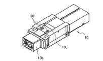
本発明の実施形態を説明する。図1は、光モジュール2の上面斜視図であり、図2はその下面斜視図である。光モジュール2は、光トランシーバが内蔵されたベース体10を備え、このベース体10にハンドル12、ロックレバー14、ロック部材16、カバー18等が装着されている。なお、図1及び図2においては、光ファイバー等のケーブルコネクタ21が装着されている。
An embodiment of the present invention will be described. FIG. 1 is a top perspective view of the
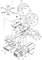
図3は、このような光モジュール2の組み立て手順を示す分解斜視図である。以下の説明において、前方向、後方向、上下方向、左右方向の用語を用いる。これらの用語は、図1〜図3により定義される。なお、前方向は、挿入方向又は先端方向と記載する場合があり、後方向は引抜方向と記載する場合がある。図1〜図3においては、光モジュールが挿抜される通信装置を図示していないが、この通信装置は光モジュールの前方向(挿入方向)に位置する。
FIG. 3 is an exploded perspective view showing the procedure for assembling such an
ベース体10は、概略直方体の外観を持ち、その前方向の端部には通信装置と光モジュールとの電気的接続を行うための端子板10aが設けられ(図1参照)、後方向の端部にはケーブルコネクタ21が装着されるコネクタ10bが設けられている(図3参照)。
The
また、ベース体10の上方向の面には、バネ20を収納するバネ収納部10cが形成され、左右方向からベース体10を貫通するベース体側のピン穴10dが形成されている。このピン穴10dには揺動ピン22が挿入される。
A
ハンドル12は、通信装置に対して光モジュール2を挿脱する際に摘まれるレバーであり、リング状の取手部12a、スライド部12b、抜止部12c、キー12dを備えている。なお、本明細書において、リング状と記載する場合には、例えば、C字形状のように一部が欠けた形状が含まれる。取手部12aの後方向の端縁領域には抜止部12cが形成され、前方向の端部領域にはスライド部12bが形成されている。取手部12aがリング状に形成されているのは、後述するようにユーザが指をリングの内側に挿入することにより、光モジュールのロック解除及び引抜きが行えるようにするためである。スライド部12bは、凹溝に形成されて、ロックレバー14が前後運動する際のガイド溝として機能する。また、スライド部12bの前方向には、概略直方体のキー12dが左右方向に突設されている。
The
ロックレバー14は、本体部14a、本体部14aの前方向端部に設けられた案内部14b、後方向に設けられた指係止部14c、バネ止部14dを備える。また、本体部14aは、スライダー14e、ロック保持部14gを含んでいる。
The
案内部14bは、本体部14aから左右方向に突設された概略三角柱体である。そして、鋭角をなす案内部14bの一方の面が本体部14aの面(ロックレバー14の移動面)に平行で、他方の面が下方に傾斜している。この傾斜した面を案内面14fと記載する。バネ止部14dは、本体部14aの下面に形成され、かつ、本体部14aの面と略直交している。
The
ロック保持部14gは案内部14bより所定量後方位置に形成されたテーパ面である。
The
ロック部材16は、本体部16a、側板16b、ロック爪16c、ロック解除爪16d、案内当接部16e、揺動ピン穴16fを備える。
The
ロック部材16の本体部16aの左右の側縁に側板16bが設けられている。揺動ピン穴16fは、ロック爪16cとロック解除爪16dとの中間位置の側板16bを貫通することにより形成されている。
ロック爪16cは、側板16bの前方向の端部領域に形成されて、迎面16g及びロック面16hを備える。迎面16gは下方向に向かって後方向側に傾斜した面である。一方、ロック面16hは本体部16aの面と略直交する面である。
The
ロック解除爪16dは、側板16bの後方向の端部領域に形成されて、本体部16aの面と鋭角をなすスライド面16jを持つ。即ち、スライド面16jは、ロックレバー14の案内面14fと対面する面である。
The unlocking
カバー18は、本体部18a、側板18b、ベース体10にカバー18を固定するためのビス板18c、キー嵌合穴18dを備えて、ビス23によりベース体10に固定する。
The
なお、上述したロックレバー14、ロック部材16等の各部材は樹脂成形又は板金により形成することが可能である。しかし、ロック部材16におけるロック爪16cに対して摩耗や損傷が危惧される場合には、板金により形成することが好ましい。板金は、各部材の小型化に適し、かつ、小型化等した際に発生する強度不足の抑制が行える観点から好ましい。
Each member such as the
次に、上述した光モジュール2の組み立て手順を説明する。図4〜図7は、この組み立て手順を示す図である。
Next, the assembly procedure of the
先ず、ベース体10のバネ収納部10cにバネ20を挿入する(図4参照)。その後、ハンドル12のスライド部12bにロックレバー14のスライダー14eを挿入しながら、これらをベース体10に取り付ける(図5参照)。このとき、ロックレバー14のバネ止部14dでバネ20を後方向に圧縮しながら取り付ける。
First, the
ハンドル12とロックレバー14とを取り付けると、ロックレバー14の外側にハンドル12が存在するようになる。そして、ロック解除を行う際にロックレバー14が移動する方向には、抜止部12cが位置する。従って、ユーザが不用意にロックレバー14に接触しようとしてもロックレバー14はハンドル12により保護されるので、不用意に光モジュール2が取り外される事態が防止できる。
When the
次に、ロック部材16を取り付ける(図6参照)。ロック部材16を取り付ける際には、ロック解除爪16dがロックレバー14の案内部14bを包み込むように差し込む。このとき、バネ20の一端がロックレバー14のバネ止部14dに当接して、ロックレバー14を前方向に付勢しているので、ロックレバー14はバネ収納部10cから前方向に飛び出すようになる。そこで、組み立て時には、ロックレバー14を押さえながら、ロック部材16を組み込む。ロック部材16を組み込んだ後、揺動ピン22を挿入して、ロック部材16をベース体10に揺動自在に支持する。
Next, the
ロック部材16を組み立てた後、カバー18でロックレバー14を抑えながらベース体10にビス23により固定する(図7参照)。なお、カバー18を取り付ける際には、キー嵌合穴18dにキー23を挿入する。これにより、ハンドル12はカバー18を介してベース体10に固定される。
After assembling the
このようにして組み立てられた光モジュール2を通信装置に装着し、また通信装置から引き抜く際の動作を説明する。図8(a)は光モジュールを挿入する際の光モジュール2の側面図、図8(b)は通信装置にロックされた光モジュール2の側面図、図8(c)は光モジュール2を通信装置から引き抜く際の側面図である。なお、図8(a)〜図8(c)においては、動作が容易に解るように、ベース体10等は適宜省略している。
The operation when the
光モジュール2を通信装置に装着する場合には、ユーザは光モジュール2を通信装置に設けられているスロットに差し込む。このとき、人差し指をリング状の指係止部14cに挿入して、人差し指と親指とでハンドル12の抜止部12cとロックレバー14の指係止部14cとを摘む。ハンドル12とロックレバー14とを挟むことにより、ロックレバー14はバネ20の力に抗して後方向に移動する。そして、抜止部12cに指係止部14cが当接して、移動が停止する。
When the
ロックレバー14の後方向に移動すると、ロックレバー14の案内部14bがロック部材16のロック解除爪16dに当接する。そして、更にロックレバー14を後方移動させると、案内部14bはロック解除爪16dのスライド面16jに沿って案内される。スライド面16jは後退するロックレバー14の案内面14fに対してテーパをなすので、ロック部材16は揺動ピン22を揺動軸として、図8(a)において反時計回りの方向に傾く。従って、前方向に設けられているロック爪16cは上方向に移動して、ロックされる通信装置のロック溝24から離れる(図8(a)参照)。
When the
この状態で、ユーザが指を離すと、バネ20の復元力でロックレバー14が前方向に移動し、ロック爪16cがロック溝24に係合して光モジュール2はロックされる(図8(b)参照)。
When the user releases the finger in this state, the
また、バネ20によりロックレバー14が前方方向に移動すると、ロック保持部14gがロック部材16の本体部16aに当接する。図8(b)の拡大図において点線Kは、本体部16aの下面を示し、この下面の端縁にロック保持部14gが当接している。従って、ロック部材16は揺動することができなくなり、ロック状態が維持される。また、ロック保持部14gはテーパ面をなすので、ロック保持部14gは滑らか、かつ、確実に本体部16aの下面端縁に当接するようになり、ロック状態の保持に対する信頼性が向上する。
Further, when the
このロック状態を解除して光モジュール2を引き抜くときは、光モジュール2を装着するときと同様に、人差し指と親指とで、抜止部12cと指係止部14cとを摘んで、ロック爪16cを上方向に移動させる(図8(c)参照)。
When the
以上説明したように、ロックレバー14はハンドル12により保護されるので、不用意に光モジュール2が取り外される事態が防止できき、かつ、ロックレバー14を後方に移動させるだけでロック解除ができるので、光モジュールの挿脱が容易に行えるようになる。
As described above, since the
2 光モジュール
10 ベース体
10a 端子板
10b コネクタ
10c バネ収納部
10d ピン穴
12 ハンドル
12a 取手部
12b スライド部
12c 抜止部
12d キー
14 ロックレバー
14a 本体部
14b 案内部
14c 指係止部
14d バネ止部
14e スライダー
14f 案内面
14g ロック保持部
16 ロック部材
16a 本体部
16b 側板
16c ロック爪
16d ロック解除爪
16e 案内当接部
16f 揺動ピン穴
16g 迎面
16h ロック面
16j スライド面
18 カバー
18a 本体部
18b 側板
18c ビス板
18d キー嵌合穴
20 バネ
22 揺動ピン
2
Claims (5)
前方向端部に、前記通信装置に形成されたロック溝と係合するロック爪が設けられると共に、後方向端部に、案内部が設けられ、かつ、前記案内部と前記ロック爪との間の位置に揺動ピンが装着されたロック部材と、
前方向端部に、前記案内部と係合するロック解除爪が設けられると共に、後方向端部に、リング状の指係止部が設けられて、バネにより前方方向に付勢されたロックレバーと、
前記光モジュールの本体をなすベース体に固定されると共に、リング状の取手部が設けられたハンドルと、を備え、
前記取手部は、前記指係止部より適宜大きいリング寸法に形成されて、当該指係止部を保護することを特徴とする光モジュールのロック機構。 An optical module locking mechanism for locking an optical module mounted on a communication device,
A lock claw that engages with a lock groove formed in the communication device is provided at the front end portion, and a guide portion is provided at the rear end portion, and between the guide portion and the lock claw. A locking member having a swing pin mounted at a position of
A lock release claw that engages with the guide portion is provided at the front end portion, and a ring-shaped finger locking portion is provided at the rear end portion, and the lock lever is urged forward by a spring. When,
A handle that is fixed to the base body forming the main body of the optical module and provided with a ring-shaped handle,
The locking mechanism of the optical module, wherein the handle is formed in a ring size that is appropriately larger than the finger locking portion to protect the finger locking portion.
前記案内部が、前記ロックレバーの先端領域から左右方向に突設する概略三角柱体であり、かつ、鋭角をなす前記柱体の一方の面が前記ロックレバーの移動面に平行で、他方の面が下方に傾斜した案内面を備え、
前記ロック解除爪が、前記案内面と対面するとスライド面を備えて、
前記ロックレバーの後方向の移動に伴い、前記スライド面が前記案内面に案内されて、前記ロック部材が前記揺動ピンを揺動軸として揺動して、前記ロック爪を前記ロック溝から待避させることを特徴とする光モジュールのロック機構。 The optical module locking mechanism according to claim 1,
The guide portion is a substantially triangular prism projecting in the left-right direction from the tip end region of the lock lever, and one surface of the pillar body forming an acute angle is parallel to the moving surface of the lock lever and the other surface Has a guide surface inclined downward,
When the unlocking claw faces the guide surface, a slide surface is provided,
As the lock lever moves backward, the slide surface is guided by the guide surface, the lock member swings about the swing pin as a swing shaft, and the lock claw is retracted from the lock groove. A locking mechanism for an optical module, wherein:
前記ロックレバーが、前記案内部より所定量後方位置にロック保持部を備えて、前記ロックレバーが前記バネの力により前方向に移動した際に、前記ロック保持部が前記ロック部材の後端縁に当接して、当該ロック部材の揺動を規制することを特徴とする光モジュールのロック機構。 The optical module locking mechanism according to claim 1 or 2,
The lock lever includes a lock holding portion at a position behind the guide portion by a predetermined amount, and when the lock lever moves forward by the force of the spring, the lock holding portion is a rear edge of the lock member. A locking mechanism for an optical module, wherein the locking mechanism restricts swinging of the locking member.
前記ロック保持部が、テーパ面であることを特徴とする光モジュールのロック機構。 An optical module locking mechanism according to claim 3,
The optical module locking mechanism, wherein the lock holding portion is a tapered surface.
前記ロック部材は、板金加工により形成されていることを特徴とする光モジュールのロック機構。 An optical module locking mechanism according to any one of claims 1 to 4,
The locking mechanism of the optical module, wherein the locking member is formed by sheet metal processing.
Priority Applications (3)
| Application Number | Priority Date | Filing Date | Title |
|---|---|---|---|
| JP2011059499A JP2012194451A (en) | 2011-03-17 | 2011-03-17 | Lock mechanism of optical module |
| US13/368,547 US20120237177A1 (en) | 2011-03-17 | 2012-02-08 | Locking mechanism of optical module |
| CN2012100757101A CN102681108A (en) | 2011-03-17 | 2012-03-19 | Locking mechanism of optical module |
Applications Claiming Priority (1)
| Application Number | Priority Date | Filing Date | Title |
|---|---|---|---|
| JP2011059499A JP2012194451A (en) | 2011-03-17 | 2011-03-17 | Lock mechanism of optical module |
Publications (1)
| Publication Number | Publication Date |
|---|---|
| JP2012194451A true JP2012194451A (en) | 2012-10-11 |
Family
ID=46813296
Family Applications (1)
| Application Number | Title | Priority Date | Filing Date |
|---|---|---|---|
| JP2011059499A Pending JP2012194451A (en) | 2011-03-17 | 2011-03-17 | Lock mechanism of optical module |
Country Status (3)
| Country | Link |
|---|---|
| US (1) | US20120237177A1 (en) |
| JP (1) | JP2012194451A (en) |
| CN (1) | CN102681108A (en) |
Cited By (2)
| Publication number | Priority date | Publication date | Assignee | Title |
|---|---|---|---|---|
| JP2014203055A (en) * | 2013-04-10 | 2014-10-27 | 日本電気株式会社 | Optical transceiver |
| JP2015121587A (en) * | 2013-12-20 | 2015-07-02 | 住友電気工業株式会社 | Optical transceiver |
Families Citing this family (32)
| Publication number | Priority date | Publication date | Assignee | Title |
|---|---|---|---|---|
| US10806385B2 (en) * | 2015-01-21 | 2020-10-20 | National Institutes For Quantum And Radiological Science And Technology | Device for measuring concentration of substance in blood, and method for measuring concentration of substance in blood |
| WO2017123247A1 (en) * | 2016-01-15 | 2017-07-20 | Senko Advanced Components, Inc. | Narrow width adapters and connectors with spring loaded remote release |
| US9595786B1 (en) | 2016-01-15 | 2017-03-14 | Senko Advanced Components, Inc. | Narrow width adapters and connectors with spring loaded remote release |
| US10158194B2 (en) | 2016-01-15 | 2018-12-18 | Senko Advanced Components, Inc. | Narrow width adapters and connectors with spring loaded remote release |
| US9726830B1 (en) | 2016-06-28 | 2017-08-08 | Senko Advanced Components, Inc. | Connector and adapter system for two-fiber mechanical transfer type ferrule |
| US10228521B2 (en) | 2016-12-05 | 2019-03-12 | Senko Advanced Components, Inc. | Narrow width adapters and connectors with modular latching arm |
| US10078188B1 (en) | 2016-12-05 | 2018-09-18 | Senko Advanced Components, Inc. | Springless push/pull fiber optic connector |
| US10185100B2 (en) | 2017-01-30 | 2019-01-22 | Senko Advanced Components, Inc | Modular connector and adapter assembly using a removable anchor device |
| US11333836B2 (en) | 2017-01-30 | 2022-05-17 | Senko Advanced Components, Inc. | Adapter for optical connectors |
| US10444444B2 (en) | 2017-01-30 | 2019-10-15 | Senko Advanced Components, Inc. | Remote release tab connector assembly |
| WO2018140981A1 (en) | 2017-01-30 | 2018-08-02 | Senko Advanced Components, Inc. | Optical connectors with reversible polarity |
| US10718910B2 (en) | 2017-05-03 | 2020-07-21 | Senko Advanced Components, Inc | Field terminated ruggedized fiber optic connector system |
| US10718911B2 (en) | 2017-08-24 | 2020-07-21 | Senko Advanced Components, Inc. | Ultra-small form factor optical connectors using a push-pull boot receptacle release |
| US11822133B2 (en) | 2017-07-14 | 2023-11-21 | Senko Advanced Components, Inc. | Ultra-small form factor optical connector and adapter |
| US10281669B2 (en) | 2017-07-14 | 2019-05-07 | Senko Advance Components, Inc. | Ultra-small form factor optical connectors |
| US10641972B2 (en) | 2017-08-17 | 2020-05-05 | Senko Advanced Components, Inc | Anti-jam alignment sleeve holder or connector housing for a ferrule assembly |
| US11002923B2 (en) | 2017-11-21 | 2021-05-11 | Senko Advanced Components, Inc. | Fiber optic connector with cable boot release having a two-piece clip assembly |
| JP7052943B2 (en) * | 2018-02-16 | 2022-04-12 | 住友電工デバイス・イノベーション株式会社 | Optical transceiver |
| US11112566B2 (en) | 2018-03-19 | 2021-09-07 | Senko Advanced Components, Inc. | Removal tool for removing a plural of micro optical connectors from an adapter interface |
| WO2019191522A1 (en) | 2018-03-28 | 2019-10-03 | Senko Advanced Components Inc | Small form factor fiber optic connector with multi-purpose boot |
| CN112088327A (en) | 2018-07-15 | 2020-12-15 | 扇港元器件股份有限公司 | Ultra-small optical connector and adapter |
| WO2020036992A1 (en) | 2018-08-13 | 2020-02-20 | Senko Advanced Components, Inc | A cable boot assembly for releasing fiber optic connector from a receptacle |
| US10921530B2 (en) | 2018-09-12 | 2021-02-16 | Senko Advanced Components, Inc. | LC type connector with push/pull assembly for releasing connector from a receptacle using a cable boot |
| WO2020055440A1 (en) | 2018-09-12 | 2020-03-19 | Senko Advanced Componetns, Inc. | Lc type connector with clip-on push/pull tab for releasing connector from a receptacle using a cable boot |
| US10921531B2 (en) | 2018-09-12 | 2021-02-16 | Senko Advanced Components, Inc. | LC type connector with push/pull assembly for releasing connector from a receptacle using a cable boot |
| US11806831B2 (en) | 2018-11-21 | 2023-11-07 | Senko Advanced Components, Inc. | Fixture and method for polishing fiber optic connector ferrules |
| US11175464B2 (en) | 2018-11-25 | 2021-11-16 | Senko Advanced Components, Inc. | Open ended spring body for use in an optical fiber connector |
| CN109856735B (en) * | 2019-02-18 | 2020-07-31 | 深圳市迅特通信技术有限公司 | Optical transceiver module |
| WO2020198755A1 (en) | 2019-03-28 | 2020-10-01 | Senko Advanced Components, Inc | Fiber optic adapter assembly |
| US11340406B2 (en) | 2019-04-19 | 2022-05-24 | Senko Advanced Components, Inc. | Small form factor fiber optic connector with resilient latching mechanism for securing within a hook-less receptacle |
| CN114026480B (en) | 2019-06-13 | 2023-05-26 | 扇港元器件有限公司 | Lever actuated latch arm for releasing fiber optic connectors from receptacle ports and method of use |
| WO2021016431A1 (en) | 2019-07-23 | 2021-01-28 | Senko Advanced Components, Inc | Ultra-small form factor receptacle for receiving a fiber optic connector opposing a ferrule assembly |
Citations (2)
| Publication number | Priority date | Publication date | Assignee | Title |
|---|---|---|---|---|
| JP2004170594A (en) * | 2002-11-19 | 2004-06-17 | Nec Corp | Locking mechanism of optical module |
| JP2007279509A (en) * | 2006-04-10 | 2007-10-25 | Murata Mfg Co Ltd | Lock structure of optical module |
Family Cites Families (7)
| Publication number | Priority date | Publication date | Assignee | Title |
|---|---|---|---|---|
| US6666484B1 (en) * | 2000-06-09 | 2003-12-23 | Jds Uniphase Corporation | Pivoting type latch for removable electronic devices |
| JP2004271950A (en) * | 2003-03-10 | 2004-09-30 | Hitachi Cable Ltd | Package with locking mechanism |
| JP4117476B2 (en) * | 2003-05-30 | 2008-07-16 | 日本電気株式会社 | Optical module, optical module / cage assembly, optical module / cage locking method and unlocking method |
| JP2005084521A (en) * | 2003-09-10 | 2005-03-31 | Toshiba Components Co Ltd | Optical communication module |
| US7317862B2 (en) * | 2004-04-13 | 2008-01-08 | Nec Corporation | Mechanism for releasing lock between optical transceiver and cage, optical transceiver, communication apparatus and method of releasing lock between optical transceiver and cage |
| JP2010101944A (en) * | 2008-10-21 | 2010-05-06 | Nec Corp | Lock mechanism for optical module |
| US8113723B2 (en) * | 2009-10-05 | 2012-02-14 | Finisar Corporation | Communications module integrated boot and release slide |
-
2011
- 2011-03-17 JP JP2011059499A patent/JP2012194451A/en active Pending
-
2012
- 2012-02-08 US US13/368,547 patent/US20120237177A1/en not_active Abandoned
- 2012-03-19 CN CN2012100757101A patent/CN102681108A/en active Pending
Patent Citations (2)
| Publication number | Priority date | Publication date | Assignee | Title |
|---|---|---|---|---|
| JP2004170594A (en) * | 2002-11-19 | 2004-06-17 | Nec Corp | Locking mechanism of optical module |
| JP2007279509A (en) * | 2006-04-10 | 2007-10-25 | Murata Mfg Co Ltd | Lock structure of optical module |
Cited By (2)
| Publication number | Priority date | Publication date | Assignee | Title |
|---|---|---|---|---|
| JP2014203055A (en) * | 2013-04-10 | 2014-10-27 | 日本電気株式会社 | Optical transceiver |
| JP2015121587A (en) * | 2013-12-20 | 2015-07-02 | 住友電気工業株式会社 | Optical transceiver |
Also Published As
| Publication number | Publication date |
|---|---|
| US20120237177A1 (en) | 2012-09-20 |
| CN102681108A (en) | 2012-09-19 |
Similar Documents
| Publication | Publication Date | Title |
|---|---|---|
| JP2012194451A (en) | Lock mechanism of optical module | |
| JP4241810B2 (en) | Electric tool | |
| US7281863B2 (en) | Module connect/disconnect structure and method for disconnecting a module using the structure | |
| US20080089649A1 (en) | Fiber optic connector release mechanism | |
| JP5718300B2 (en) | Detachable mechanism, mounting device, electronic equipment | |
| CN110161635B (en) | Optical transceiver | |
| JP2008103144A (en) | Locking mechanism of battery pack | |
| EP2693245B1 (en) | Connector | |
| JP4998566B2 (en) | Attachment / detachment structure of electromagnetic contactor and accessory unit, and assembly method of movable hook provided in accessory unit | |
| JP4752277B2 (en) | Battery lock structure in electronic equipment | |
| JP2002044207A (en) | Battery lock mechanism | |
| US9084935B2 (en) | Attachment device for an electronic apparatus | |
| JP2010101944A (en) | Lock mechanism for optical module | |
| JP2006154594A (en) | Optical module | |
| JP2004258094A (en) | Package with release mechanism | |
| JP6264740B2 (en) | Optical transceiver | |
| JP2009259635A (en) | Card adapter | |
| JP3632688B2 (en) | Battery pack, adapter and camera accessories | |
| JP6663113B2 (en) | Electronic equipment | |
| JP4023513B2 (en) | Camcorder battery pack and adapter | |
| JP5892449B1 (en) | Connector removal mechanism and optical module | |
| US20170214207A1 (en) | Extracting tool for module component | |
| JP2009169807A (en) | Electronic equipment | |
| JP2005338247A (en) | Mechanism for releasing lock of optical module, optical module and method for releasing lock state between optical module and cage | |
| JP2009289546A (en) | Power supply device |
Legal Events
| Date | Code | Title | Description |
|---|---|---|---|
| A621 | Written request for application examination |
Free format text: JAPANESE INTERMEDIATE CODE: A621 Effective date: 20140217 |
|
| A02 | Decision of refusal |
Free format text: JAPANESE INTERMEDIATE CODE: A02 Effective date: 20150303 |