JP2012194175A - Attitude determination method, position calculation method and attitude determination device - Google Patents
Attitude determination method, position calculation method and attitude determination device Download PDFInfo
- Publication number
- JP2012194175A JP2012194175A JP2011275235A JP2011275235A JP2012194175A JP 2012194175 A JP2012194175 A JP 2012194175A JP 2011275235 A JP2011275235 A JP 2011275235A JP 2011275235 A JP2011275235 A JP 2011275235A JP 2012194175 A JP2012194175 A JP 2012194175A
- Authority
- JP
- Japan
- Prior art keywords
- moving body
- sensor
- coordinate
- posture
- vector
- Prior art date
- Legal status (The legal status is an assumption and is not a legal conclusion. Google has not performed a legal analysis and makes no representation as to the accuracy of the status listed.)
- Granted
Links
Images


Classifications
-
- G—PHYSICS
- G01—MEASURING; TESTING
- G01C—MEASURING DISTANCES, LEVELS OR BEARINGS; SURVEYING; NAVIGATION; GYROSCOPIC INSTRUMENTS; PHOTOGRAMMETRY OR VIDEOGRAMMETRY
- G01C21/00—Navigation; Navigational instruments not provided for in groups G01C1/00 - G01C19/00
- G01C21/10—Navigation; Navigational instruments not provided for in groups G01C1/00 - G01C19/00 by using measurements of speed or acceleration
- G01C21/12—Navigation; Navigational instruments not provided for in groups G01C1/00 - G01C19/00 by using measurements of speed or acceleration executed aboard the object being navigated; Dead reckoning
- G01C21/16—Navigation; Navigational instruments not provided for in groups G01C1/00 - G01C19/00 by using measurements of speed or acceleration executed aboard the object being navigated; Dead reckoning by integrating acceleration or speed, i.e. inertial navigation
- G01C21/183—Compensation of inertial measurements, e.g. for temperature effects
- G01C21/188—Compensation of inertial measurements, e.g. for temperature effects for accumulated errors, e.g. by coupling inertial systems with absolute positioning systems
-
- B—PERFORMING OPERATIONS; TRANSPORTING
- B60—VEHICLES IN GENERAL
- B60G—VEHICLE SUSPENSION ARRANGEMENTS
- B60G17/00—Resilient suspensions having means for adjusting the spring or vibration-damper characteristics, for regulating the distance between a supporting surface and a sprung part of vehicle or for locking suspension during use to meet varying vehicular or surface conditions, e.g. due to speed or load
- B60G17/015—Resilient suspensions having means for adjusting the spring or vibration-damper characteristics, for regulating the distance between a supporting surface and a sprung part of vehicle or for locking suspension during use to meet varying vehicular or surface conditions, e.g. due to speed or load the regulating means comprising electric or electronic elements
- B60G17/018—Resilient suspensions having means for adjusting the spring or vibration-damper characteristics, for regulating the distance between a supporting surface and a sprung part of vehicle or for locking suspension during use to meet varying vehicular or surface conditions, e.g. due to speed or load the regulating means comprising electric or electronic elements characterised by the use of a specific signal treatment or control method
-
- B—PERFORMING OPERATIONS; TRANSPORTING
- B60—VEHICLES IN GENERAL
- B60G—VEHICLE SUSPENSION ARRANGEMENTS
- B60G17/00—Resilient suspensions having means for adjusting the spring or vibration-damper characteristics, for regulating the distance between a supporting surface and a sprung part of vehicle or for locking suspension during use to meet varying vehicular or surface conditions, e.g. due to speed or load
- B60G17/015—Resilient suspensions having means for adjusting the spring or vibration-damper characteristics, for regulating the distance between a supporting surface and a sprung part of vehicle or for locking suspension during use to meet varying vehicular or surface conditions, e.g. due to speed or load the regulating means comprising electric or electronic elements
- B60G17/019—Resilient suspensions having means for adjusting the spring or vibration-damper characteristics, for regulating the distance between a supporting surface and a sprung part of vehicle or for locking suspension during use to meet varying vehicular or surface conditions, e.g. due to speed or load the regulating means comprising electric or electronic elements characterised by the type of sensor or the arrangement thereof
-
- B—PERFORMING OPERATIONS; TRANSPORTING
- B60—VEHICLES IN GENERAL
- B60G—VEHICLE SUSPENSION ARRANGEMENTS
- B60G17/00—Resilient suspensions having means for adjusting the spring or vibration-damper characteristics, for regulating the distance between a supporting surface and a sprung part of vehicle or for locking suspension during use to meet varying vehicular or surface conditions, e.g. due to speed or load
- B60G17/015—Resilient suspensions having means for adjusting the spring or vibration-damper characteristics, for regulating the distance between a supporting surface and a sprung part of vehicle or for locking suspension during use to meet varying vehicular or surface conditions, e.g. due to speed or load the regulating means comprising electric or electronic elements
- B60G17/0195—Resilient suspensions having means for adjusting the spring or vibration-damper characteristics, for regulating the distance between a supporting surface and a sprung part of vehicle or for locking suspension during use to meet varying vehicular or surface conditions, e.g. due to speed or load the regulating means comprising electric or electronic elements characterised by the regulation being combined with other vehicle control systems
-
- G—PHYSICS
- G01—MEASURING; TESTING
- G01C—MEASURING DISTANCES, LEVELS OR BEARINGS; SURVEYING; NAVIGATION; GYROSCOPIC INSTRUMENTS; PHOTOGRAMMETRY OR VIDEOGRAMMETRY
- G01C21/00—Navigation; Navigational instruments not provided for in groups G01C1/00 - G01C19/00
- G01C21/10—Navigation; Navigational instruments not provided for in groups G01C1/00 - G01C19/00 by using measurements of speed or acceleration
- G01C21/12—Navigation; Navigational instruments not provided for in groups G01C1/00 - G01C19/00 by using measurements of speed or acceleration executed aboard the object being navigated; Dead reckoning
-
- G—PHYSICS
- G01—MEASURING; TESTING
- G01C—MEASURING DISTANCES, LEVELS OR BEARINGS; SURVEYING; NAVIGATION; GYROSCOPIC INSTRUMENTS; PHOTOGRAMMETRY OR VIDEOGRAMMETRY
- G01C21/00—Navigation; Navigational instruments not provided for in groups G01C1/00 - G01C19/00
- G01C21/26—Navigation; Navigational instruments not provided for in groups G01C1/00 - G01C19/00 specially adapted for navigation in a road network
- G01C21/28—Navigation; Navigational instruments not provided for in groups G01C1/00 - G01C19/00 specially adapted for navigation in a road network with correlation of data from several navigational instruments
-
- G—PHYSICS
- G01—MEASURING; TESTING
- G01C—MEASURING DISTANCES, LEVELS OR BEARINGS; SURVEYING; NAVIGATION; GYROSCOPIC INSTRUMENTS; PHOTOGRAMMETRY OR VIDEOGRAMMETRY
- G01C25/00—Manufacturing, calibrating, cleaning, or repairing instruments or devices referred to in the other groups of this subclass
- G01C25/005—Manufacturing, calibrating, cleaning, or repairing instruments or devices referred to in the other groups of this subclass initial alignment, calibration or starting-up of inertial devices
-
- G—PHYSICS
- G01—MEASURING; TESTING
- G01C—MEASURING DISTANCES, LEVELS OR BEARINGS; SURVEYING; NAVIGATION; GYROSCOPIC INSTRUMENTS; PHOTOGRAMMETRY OR VIDEOGRAMMETRY
- G01C9/00—Measuring inclination, e.g. by clinometers, by levels
- G01C9/02—Details
- G01C9/08—Means for compensating acceleration forces due to movement of instrument
-
- G—PHYSICS
- G01—MEASURING; TESTING
- G01G—WEIGHING
- G01G19/00—Weighing apparatus or methods adapted for special purposes not provided for in the preceding groups
- G01G19/08—Weighing apparatus or methods adapted for special purposes not provided for in the preceding groups for incorporation in vehicles
- G01G19/086—Weighing apparatus or methods adapted for special purposes not provided for in the preceding groups for incorporation in vehicles wherein the vehicle mass is dynamically estimated
-
- G—PHYSICS
- G01—MEASURING; TESTING
- G01S—RADIO DIRECTION-FINDING; RADIO NAVIGATION; DETERMINING DISTANCE OR VELOCITY BY USE OF RADIO WAVES; LOCATING OR PRESENCE-DETECTING BY USE OF THE REFLECTION OR RERADIATION OF RADIO WAVES; ANALOGOUS ARRANGEMENTS USING OTHER WAVES
- G01S19/00—Satellite radio beacon positioning systems; Determining position, velocity or attitude using signals transmitted by such systems
- G01S19/38—Determining a navigation solution using signals transmitted by a satellite radio beacon positioning system
- G01S19/39—Determining a navigation solution using signals transmitted by a satellite radio beacon positioning system the satellite radio beacon positioning system transmitting time-stamped messages, e.g. GPS [Global Positioning System], GLONASS [Global Orbiting Navigation Satellite System] or GALILEO
- G01S19/42—Determining position
-
- H—ELECTRICITY
- H04—ELECTRIC COMMUNICATION TECHNIQUE
- H04W—WIRELESS COMMUNICATION NETWORKS
- H04W52/00—Power management, e.g. TPC [Transmission Power Control], power saving or power classes
- H04W52/02—Power saving arrangements
- H04W52/0209—Power saving arrangements in terminal devices
- H04W52/0251—Power saving arrangements in terminal devices using monitoring of local events, e.g. events related to user activity
- H04W52/0254—Power saving arrangements in terminal devices using monitoring of local events, e.g. events related to user activity detecting a user operation or a tactile contact or a motion of the device
-
- B—PERFORMING OPERATIONS; TRANSPORTING
- B60—VEHICLES IN GENERAL
- B60G—VEHICLE SUSPENSION ARRANGEMENTS
- B60G2400/00—Indexing codes relating to detected, measured or calculated conditions or factors
- B60G2400/05—Attitude
-
- B—PERFORMING OPERATIONS; TRANSPORTING
- B60—VEHICLES IN GENERAL
- B60G—VEHICLE SUSPENSION ARRANGEMENTS
- B60G2400/00—Indexing codes relating to detected, measured or calculated conditions or factors
- B60G2400/05—Attitude
- B60G2400/051—Angle
- B60G2400/0512—Pitch angle
-
- B—PERFORMING OPERATIONS; TRANSPORTING
- B60—VEHICLES IN GENERAL
- B60G—VEHICLE SUSPENSION ARRANGEMENTS
- B60G2400/00—Indexing codes relating to detected, measured or calculated conditions or factors
- B60G2400/05—Attitude
- B60G2400/051—Angle
- B60G2400/0513—Yaw angle
-
- Y—GENERAL TAGGING OF NEW TECHNOLOGICAL DEVELOPMENTS; GENERAL TAGGING OF CROSS-SECTIONAL TECHNOLOGIES SPANNING OVER SEVERAL SECTIONS OF THE IPC; TECHNICAL SUBJECTS COVERED BY FORMER USPC CROSS-REFERENCE ART COLLECTIONS [XRACs] AND DIGESTS
- Y02—TECHNOLOGIES OR APPLICATIONS FOR MITIGATION OR ADAPTATION AGAINST CLIMATE CHANGE
- Y02D—CLIMATE CHANGE MITIGATION TECHNOLOGIES IN INFORMATION AND COMMUNICATION TECHNOLOGIES [ICT], I.E. INFORMATION AND COMMUNICATION TECHNOLOGIES AIMING AT THE REDUCTION OF THEIR OWN ENERGY USE
- Y02D30/00—Reducing energy consumption in communication networks
- Y02D30/70—Reducing energy consumption in communication networks in wireless communication networks
Abstract
Description
本発明は、移動体に対するセンサーの姿勢を判定する方法等に関する。 The present invention relates to a method for determining the attitude of a sensor with respect to a moving object.
いわゆるシームレス測位やモーションセンシング、姿勢制御など様々な分野において、センサーの活用が注目されている。センサーとしては、加速度センサーやジャイロセンサー、圧力センサー、地磁気センサーなどが広く知られている。センサーの計測結果を利用して慣性航法演算を行って移動体(例えば自転車や自動車、電車、船、飛行機など)の位置算出を行う技術も考案されている。 In various fields such as so-called seamless positioning, motion sensing, and attitude control, the use of sensors is drawing attention. As sensors, acceleration sensors, gyro sensors, pressure sensors, geomagnetic sensors, and the like are widely known. A technique for calculating the position of a moving body (for example, a bicycle, a car, a train, a ship, an airplane, etc.) by performing inertial navigation calculation using the measurement result of the sensor has been devised.
慣性航法演算においては、センサーの計測結果に含まれ得る種々の誤差成分に起因して位置算出の正確性が低下するという問題があり、位置算出の正確性を向上させるための様々な技術が考案されている。例えば、特許文献1には、移動体の移動方向に関する制約条件を利用して、カルマンフィルターを適用して慣性航法演算結果を補正する技術が開示されている。
In inertial navigation calculation, there is a problem that the accuracy of position calculation is reduced due to various error components that can be included in the measurement result of the sensor, and various techniques for improving the accuracy of position calculation have been devised. Has been. For example,
特許文献1の技術は、センサーの計測結果には誤差が含まれることを前提とし、移動体の移動方向に関する制約条件を利用して、慣性航法演算結果である移動体の位置や速度といった諸量に含まれる誤差を推定するものである。但し、この技術は、センサーの座標系と移動体の座標系との正確な対応関係を把握していることが前提である。
The technique of
センサーの計測結果はセンサーの座標系(ローカル座標系)での値である。移動体の座標系での値ではない。従って、移動体の移動方向に関する制約条件を利用する場合には、センサーの座標系と移動体の座標系との間で座標変換を行うか、或いは、センサーの座標系と移動体の座標系とがぴったり一致するようにセンサーを移動体に固定する必要がある。しかし、キャリブレーションを行うとしても、センサーの座標系から移動体の座標系に正確に変換することは困難であるし、センサーの座標系と移動体の座標系とがぴったり一致するようにセンサーを移動体に固定するのも困難である。僅かではあるが誤差が発生し得るし、時間が経過すると誤差が大きくなり得る。 The measurement result of the sensor is a value in the sensor coordinate system (local coordinate system). It is not a value in the coordinate system of the moving object. Therefore, when using the constraint condition regarding the moving direction of the moving body, coordinate conversion between the coordinate system of the sensor and the coordinate system of the moving body, or the coordinate system of the sensor and the coordinate system of the moving body It is necessary to fix the sensor to the moving body so that they match exactly. However, even if calibration is performed, it is difficult to accurately convert from the sensor coordinate system to the moving object coordinate system, and the sensor coordinate system and the moving object coordinate system must be matched exactly. It is also difficult to fix to a moving body. A slight error can occur, and the error can increase over time.
また、慣性航法用のセンサーを備えた携帯型電話機やナビゲーション装置、PDA(Personal Digital Assistant)、パソコンといった持ち運び可能な電子機器を移動体に持ち込んで配置し、その電子機器で慣性航法演算を行う場合には、センサーの座標系と移動体の座標系との対応関係を正確に把握することは至難である。 Also, when portable electronic devices such as mobile phones equipped with inertial navigation sensors, navigation devices, PDAs (Personal Digital Assistants), and personal computers are brought into the mobile unit and placed, and the mobile device performs inertial navigation calculations. Therefore, it is very difficult to accurately grasp the correspondence between the coordinate system of the sensor and the coordinate system of the moving body.
センサーの座標系と移動体の座標系との間で正確な座標変換ができない場合は、センサーの座標系と移動体の座標系との間で辻褄が合わなくなるため、慣性航法演算結果に誤差が生じる。また、慣性航法演算を継続するにつれて、実際の位置と演算した位置との乖離が徐々に大きくなっていく傾向があった。 If accurate coordinate conversion between the coordinate system of the sensor and the coordinate system of the moving body is not possible, there will be an inconsistency between the sensor coordinate system and the coordinate system of the mobile object. Arise. Further, as the inertial navigation calculation is continued, the deviation between the actual position and the calculated position tends to gradually increase.
センサーの座標系と移動体の座標系との正確な対応関係を把握するためには、移動体に対するセンサーの正確な姿勢を判定する必要がある。 In order to grasp an accurate correspondence between the coordinate system of the sensor and the coordinate system of the moving body, it is necessary to determine an accurate posture of the sensor with respect to the moving body.
本発明は上述した課題に鑑みて為されたものであり、その目的とするところは、移動体に対するセンサーの姿勢を判定するための新たな手法を提案することにある。 The present invention has been made in view of the above-described problems, and an object thereof is to propose a new method for determining the attitude of a sensor with respect to a moving body.
以上の課題を解決するための第1の形態は、移動体に設置された移動ベクトルを計測するセンサーが前記移動ベクトルを計測することと、前記移動体が移動を開始した際に前記センサーが計測した前記移動ベクトルを用いて、前記移動体に対する前記センサーの姿勢を判定することと、を含む姿勢判定方法である。 A first form for solving the above problems is that a sensor that measures a movement vector installed on a moving body measures the movement vector, and that the sensor measures when the moving body starts moving. And determining the attitude of the sensor with respect to the moving body using the movement vector.
また、他の形態として、移動体に設置された移動ベクトルを計測するセンサーが前記移動体が移動を開始した際に計測した前記移動ベクトルを用いて、前記移動体に対する前記センサーの姿勢を判定する姿勢判定装置を構成してもよい。 As another form, a sensor for measuring a movement vector installed on the moving body determines the attitude of the sensor relative to the moving body using the movement vector measured when the moving body starts moving. An attitude determination device may be configured.
この第1の形態等によれば、移動体が移動を開始した際にセンサーが計測した移動ベクトルを用いて、移動体に対するセンサーの姿勢を判定する。移動ベクトルは、移動体の加速度ベクトルや速度ベクトルといった、移動体の移動に関するベクトルのことを意味する。また、移動体に対するセンサーの姿勢とは、移動体に対するセンサーの相対的な姿勢のことを意味する。実施形態で詳細に後述するが、移動体が移動を開始した際にセンサーにより計測された移動ベクトルを用いることで、移動体に対するセンサーの姿勢を判定することができる。 According to the first embodiment, the posture of the sensor with respect to the moving body is determined using the movement vector measured by the sensor when the moving body starts moving. The movement vector means a vector related to movement of the moving body, such as an acceleration vector or a velocity vector of the moving body. The sensor posture with respect to the moving body means a relative posture of the sensor with respect to the moving body. As will be described later in detail in the embodiment, the posture of the sensor with respect to the moving body can be determined by using the movement vector measured by the sensor when the moving body starts moving.
また、第2の形態として、第1の形態の姿勢判定方法であって、前記移動体が停止している場合に、前記移動体の速度に関する第1の制約条件を用いて、前記センサーの計測結果を補償すること、を更に含む姿勢判定方法を構成してもよい。 Further, as a second mode, in the posture determination method according to the first mode, when the moving body is stopped, measurement of the sensor is performed using the first constraint on the speed of the moving body. You may comprise the attitude | position determination method which further includes compensating a result.
この第2の形態によれば、移動体が停止している場合に、移動体の速度に関する第1の制約条件を用いて、センサーの計測結果を補償する。これにより、第1の形態と相まって、移動体が停止している場合に補償された移動ベクトルを用いてセンサーの姿勢を判定することができるようになり、姿勢判定をより精確に行うことが可能となる。 According to this 2nd form, when the moving body has stopped, the measurement result of a sensor is compensated using the 1st constraint regarding the speed of a moving body. Thereby, coupled with the first embodiment, the posture of the sensor can be determined using the compensated movement vector when the moving body is stopped, and the posture determination can be performed more accurately. It becomes.
また、第3の形態として、第1又は第2の形態の姿勢判定方法であって、前記姿勢を判定することは、前記移動体に対する前記姿勢のロール成分を判定せず、ピッチ成分及びヨー成分のうちの少なくも一方を判定することである、姿勢判定方法を構成してもよい。 Further, as a third mode, in the posture determination method according to the first or second mode, the determination of the posture does not determine a roll component of the posture with respect to the moving body, and a pitch component and a yaw component An attitude determination method that determines at least one of them may be configured.
この第3の形態によれば、移動体に対する姿勢のロール成分を判定せず、ピッチ成分及びヨー成分のうちの少なくも一方を判定することで、センサーの姿勢判定を簡易に行うことができる。 According to the third aspect, the posture determination of the sensor can be easily performed by determining at least one of the pitch component and the yaw component without determining the roll component of the posture with respect to the moving body.
また、第4の形態として、第1〜第3の何れかの形態の姿勢判定方法であって、前記移動ベクトルを計測することは、前記移動体の移動空間を定める座標系である絶対座標系での移動ベクトルを計測することであり、前記姿勢を判定することは、前記移動ベクトルと、前記絶対座標系で表した前記センサーの向きとを用いて、前記センサーの前記姿勢を判定することである、姿勢判定方法を構成してもよい。 Further, as a fourth mode, the posture determination method according to any one of the first to third modes, wherein the measurement of the movement vector is an absolute coordinate system that is a coordinate system that defines a movement space of the moving body The determination of the posture is performed by determining the posture of the sensor using the movement vector and the orientation of the sensor expressed in the absolute coordinate system. A certain attitude determination method may be configured.
この第4の形態によれば、移動体の移動空間を定める絶対座標系での移動ベクトルと、絶対座標系で表したセンサーの向きとを用いて、移動体に対するセンサーの姿勢を判定する。絶対座標系で表したセンサーの向きが分かれば、絶対座標系での移動ベクトルを、センサーの座標系に座標変換することができる。そして、変換後の移動ベクトルを用いることで、センサーの姿勢を適切に判定することができる。 According to the fourth embodiment, the attitude of the sensor with respect to the moving body is determined using the movement vector in the absolute coordinate system that defines the moving space of the moving body and the orientation of the sensor expressed in the absolute coordinate system. If the orientation of the sensor expressed in the absolute coordinate system is known, the movement vector in the absolute coordinate system can be coordinate-converted into the sensor coordinate system. And the attitude | position of a sensor can be determined appropriately by using the movement vector after conversion.
また、第5の形態として、第1〜第3の何れかの形態の姿勢判定方法であって、前記姿勢を判定することは、前記移動体の停止時に前記センサーにより計測された移動ベクトルと、移動を開始した際に計測された移動ベクトルとを用いて、前記センサーの計測座標系であるローカル座標系における速度ベクトルを算出することと、前記速度ベクトルを用いて前記センサーの姿勢を判定することと、を含む姿勢判定方法を構成してもよい。 Further, as a fifth mode, in the posture determination method according to any one of the first to third modes, the determination of the posture includes a movement vector measured by the sensor when the moving body is stopped, Calculating a velocity vector in a local coordinate system, which is a measurement coordinate system of the sensor, using the movement vector measured when the movement is started, and determining the attitude of the sensor using the velocity vector A posture determination method including the above may be configured.
この第5の形態によれば、前記移動体の停止時に前記センサーにより計測された移動ベクトルと、移動を開始した際に計測された移動ベクトルとを用いて、前記センサーの計測座標系であるローカル座標系における速度ベクトルを算出することで、前記センサーのバイアス誤差等を取り除いた速度ベクトルを算出することが可能となる。 According to the fifth aspect, the local coordinate system of the sensor is used by using the movement vector measured by the sensor when the moving body is stopped and the movement vector measured when the movement is started. By calculating the velocity vector in the coordinate system, it is possible to calculate the velocity vector from which the bias error of the sensor is removed.
また、第6の形態として、第1〜第5の何れかの形態の姿勢判定方法であって、前記姿勢を判定することは、前記移動体の停止が解除されて前記移動体の速度又は加速度が所定の閾値に達した時の前記移動ベクトルを用いて前記姿勢を判定することである、姿勢判定方法を構成してもよい。 Further, as a sixth aspect, the posture determination method according to any one of the first to fifth aspects, wherein the determination of the posture is performed by releasing the stop of the moving body and speed or acceleration of the moving body. A posture determination method may be configured in which the posture is determined using the movement vector when the value reaches a predetermined threshold.
この第6の形態によれば、移動体の停止が解除されて移動体の速度又は加速度が所定の閾値に達した時の移動ベクトルを用いて姿勢を判定する。移動体の停止が解除されてもすぐには姿勢判定を行わず、移動体の速度又は加速度がある程度の大きさとなった時点で姿勢判定を行うようにすることで、姿勢判定の正確性を向上させることができる。 According to the sixth aspect, the posture is determined using the movement vector when the stop of the moving body is released and the speed or acceleration of the moving body reaches a predetermined threshold. Posture determination is not performed immediately after the stop of the moving body, but posture determination is performed when the speed or acceleration of the moving body reaches a certain level, thereby improving posture determination accuracy. Can be made.
また、第7の形態として、第1〜第6の何れかの形態の姿勢判定方法を用いて前記姿勢を判定することと、前記姿勢と前記移動ベクトルとを用いて前記移動体の位置を算出することと、を含む位置算出方法を構成してもよい。 Further, as a seventh mode, the posture is determined using the posture determination method of any one of the first to sixth modes, and the position of the moving body is calculated using the posture and the movement vector. And a position calculation method including:
この第7の形態によれば、上記の形態の姿勢判定方法を用いて判定した姿勢と移動ベクトルとを用いることで、移動体の位置を適切に算出することができる。 According to the seventh aspect, the position of the moving body can be appropriately calculated by using the posture and the movement vector determined using the posture determination method of the above-described form.
また、第8の形態として、第7の形態の位置算出方法であって、前記位置を算出することは、前記移動ベクトルを用いて前記絶対座標系での前記移動体の絶対座標位置を算出することと、前記姿勢と前記絶対座標系で表した前記センサーの向きとを用いて、前記絶対座標位置を前記移動体を基準とする移動体座標位置に座標変換することと、前記移動体座標位置と、前記移動体の移動方向に関する第2の制約条件とを用いて、前記絶対座標位置を補正することと、を含む、位置算出方法を構成してもよい。 Further, as an eighth aspect, in the position calculation method according to the seventh aspect, calculating the position calculates an absolute coordinate position of the moving body in the absolute coordinate system using the movement vector. And using the orientation and the orientation of the sensor expressed in the absolute coordinate system, the absolute coordinate position is converted to a moving body coordinate position based on the moving body, and the moving body coordinate position And correcting the absolute coordinate position using a second constraint condition relating to the moving direction of the moving body may be configured.
この第8の形態によれば、移動ベクトルを用いて絶対座標系での移動体の絶対座標位置を算出する。例えば、絶対座標系での移動ベクトルを積分することで、移動体の位置を算出する。絶対座標系と移動体を基準とする座標系とを結び付けるためには、移動体に対するセンサーの相対的な姿勢と、絶対座標系で表したセンサーの向きとが必要となる。そこで、上記の形態の姿勢判定方法を用いて判定したセンサーの姿勢と、絶対座標系で表したセンサーの向きとを用いて、絶対座標位置を移動体座標位置に座標変換する。これにより、移動体を基準とする座標系での演算が可能となる。その上で、移動体座標位置と移動体の移動方向に関する第2の制約条件とを用いることで、移動体の絶対座標位置を適切に補正することができる。 According to the eighth embodiment, the absolute coordinate position of the moving body in the absolute coordinate system is calculated using the movement vector. For example, the position of the moving body is calculated by integrating the movement vector in the absolute coordinate system. In order to connect the absolute coordinate system and the coordinate system based on the moving body, the relative posture of the sensor with respect to the moving body and the orientation of the sensor expressed in the absolute coordinate system are required. Therefore, the absolute coordinate position is coordinate-converted to the moving body coordinate position by using the sensor posture determined using the posture determination method of the above-described form and the sensor orientation expressed in the absolute coordinate system. Thereby, the calculation in the coordinate system with the moving body as a reference becomes possible. In addition, the absolute coordinate position of the moving object can be appropriately corrected by using the moving object coordinate position and the second constraint condition relating to the moving direction of the moving object.
以下、図面を参照して、本発明の好適な実施形態の一例について説明する。但し、本発明を適用可能な実施形態が以下説明する実施形態に限定されるわけでないことは勿論である。 Hereinafter, an example of a preferred embodiment of the present invention will be described with reference to the drawings. However, it goes without saying that embodiments to which the present invention can be applied are not limited to the embodiments described below.
1.原理
1−1.全体システム
図1は、本実施形態における姿勢判定方法及び位置算出方法に係る全体システムのシステム構成の一例を示す図である。全体システムは、センサー3が搭載された移動体を有するシステムとして構成される。移動体は、自転車や自動車(四輪自動車及びバイクを含む)、電車、飛行機、船等の何れでもよいが、本実施形態では四輪自動車として説明する。
1. Principle 1-1. Overall System FIG. 1 is a diagram illustrating an example of a system configuration of an overall system according to a posture determination method and a position calculation method in the present embodiment. The entire system is configured as a system having a moving body on which the
本実施形態では、3種類の座標系を定義する。第1の座標系は、センサー3に対応付けられたセンサー座標系であるローカル座標系である。本明細書では、ローカル座標系のことをL(Local)フレームとも言う。ローカル座標系は、センサー3に対応付けられた三次元直交座標系であり、本実施形態では、ローカル座標系の3軸をx軸、y軸及びz軸と表記する。
In this embodiment, three types of coordinate systems are defined. The first coordinate system is a local coordinate system that is a sensor coordinate system associated with the
第2の座標系は、移動体に対応付けられた移動体座標系である。本明細書では、移動体座標系のことをV(Vehicle)フレームとも言う。Vフレームは、例えば、移動体の前方を正とする前後方向をロール軸(R軸)、右方を正とする左右方向をピッチ軸(P軸)、鉛直下方を正とする上下方向をヨー軸(Q軸)とする三次元直交座標系として定義される。本実施形態では、移動体座標系の3軸をR軸、P軸及びQ軸と表記する。 The second coordinate system is a moving body coordinate system associated with the moving body. In this specification, the moving body coordinate system is also referred to as a V (Vehicle) frame. The V frame has, for example, a roll axis (R axis) in which the front side of the moving body is positive, a pitch axis (P axis) in which the right side is positive, and a vertical direction in which the vertical direction is positive. It is defined as a three-dimensional orthogonal coordinate system with an axis (Q axis). In the present embodiment, the three axes of the moving body coordinate system are expressed as an R axis, a P axis, and a Q axis.
第3の座標系は、移動体の移動空間を定める座標系である絶対座標系である。本明細書では、絶対座標系のことをA(Absolute)フレームとも言う。Aフレームは、例えば、北東下座標系として知られるNED(North East Down)座標系や、地球中心地球固定座標系として知られるECEF(Earth Centered Earth Fixed)座標系として定義される。本実施形態では、絶対座標系の3軸をX軸、Y軸及びZ軸と表記する。 The third coordinate system is an absolute coordinate system that is a coordinate system that defines a movement space of the moving object. In this specification, the absolute coordinate system is also referred to as an A (Absolute) frame. The A frame is defined, for example, as an NED (North East Down) coordinate system known as a northeast lower coordinate system or an ECEF (Earth Centered Earth Fixed) coordinate system known as an earth-centered earth fixed coordinate system. In the present embodiment, the three axes of the absolute coordinate system are expressed as an X axis, a Y axis, and a Z axis.
センサー3は、移動体に搭載される各種のセンサーである。例えば、センサー3の計測結果を利用して自立的に位置算出や速度算出を行う慣性航法システムに適用する場合は、センサー3として、加速度センサー3Aや姿勢センサー3Bといった慣性航法用のセンサー(慣性センサー)が用いられる。
The
加速度センサー3Aは、移動体の加速度をローカル座標系で検出するセンサーであり、例えばMEMS(Micro Electro Mechanical Systems)の技術を利用したMEMSセンサーが用いられる。加速度センサー3Aは移動体に固定される。加速度センサー3Aが計測した値は、ローカル座標系で計測した移動体の加速度となる。
The
姿勢センサー3Bは、絶対座標系におけるセンサー3の向きである絶対姿勢を検出するためのセンサーであり、例えばジャイロセンサー3Cや磁気センサーといったセンサーが用いられる。姿勢センサー3Bは、ジャイロセンサー3Cや磁気センサー単体として構成してもよいし、これらを組み合わせて構成してもよい。また、加速度センサーを含んで姿勢センサー3Bを構成してもよい。姿勢センサー3Bは移動体に固定される。姿勢センサー3Bが計測した値は、絶対座標系で表したセンサー3の向きとなる。
The
移動体の加速度や速度は、方向及び大きさを持っている。そのため、本明細書では、スカラーとベクトルとを適宜区別して説明する。原則として、加速度や速度と言ったときは加速度や速度の大きさ(スカラー量)を表すものとし、加速度ベクトルや速度ベクトルと言ったときは方向及び大きさを考慮した加速度及び速度を表すものとする。また、本実施形態では、移動体の加速度ベクトル及び速度ベクトルを総称して、移動体の「移動ベクトル」と呼ぶ。なお、各座標系において定義される諸量を明確にするため、各諸量を表す文言の先頭に座標系の種類を付して説明する。例えば、ローカル座標系で表した加速度ベクトルのことを「ローカル座標加速度ベクトル」と称し、絶対座標系で表した加速度ベクトルのことを「絶対座標加速度ベクトル」と称する。他の諸量についても同様である。 The acceleration and speed of the moving body have a direction and a size. For this reason, in this specification, a scalar and a vector are appropriately distinguished and described. As a general rule, acceleration and velocity refer to the magnitude of acceleration and velocity (scalar amount), and acceleration vector and velocity vector represent acceleration and velocity considering direction and size. To do. In the present embodiment, the acceleration vector and the velocity vector of the moving object are collectively referred to as a “movement vector” of the moving object. In addition, in order to clarify various quantities defined in each coordinate system, a description will be given with the type of coordinate system added to the head of the word representing each quantity. For example, an acceleration vector expressed in the local coordinate system is referred to as “local coordinate acceleration vector”, and an acceleration vector expressed in the absolute coordinate system is referred to as “absolute coordinate acceleration vector”. The same applies to other quantities.
また、センサー3の姿勢は、ロール角、ピッチ角及びヨー角といったオイラー角で表される。絶対座標系で表したセンサー3の向きを「絶対姿勢」と表現し、その姿勢角のことを「絶対姿勢角」と称する。また、移動体に対するセンサー3の相対的な姿勢(相対姿勢)のことを「取付姿勢」と表現し、その姿勢角(相対姿勢角)のことを「取付姿勢角」と称する。
Further, the posture of the
また、以下の説明で参照する図面については、各種のセンサー3のブロックを二重線で示し、センサー3の計測結果を利用して演算処理を行う処理ブロックを一重線で示す。一重線で示される処理ブロックは、センサー3に搭載されるプロセッサーや、電子機器に搭載されるプロセッサー(ホストプロセッサー)が処理主体となる処理ブロックである。なお、各処理ブロックの処理の主体は、本発明を適用するシステムに応じて適宜設定可能であるものとする。
In the drawings to be referred to in the following description, blocks of
1−2.取付姿勢判定方法
本実施形態における取付姿勢判定方法について説明する。センサー3が移動体に取り付けられた場合に、移動体に対するセンサー3の相対的な姿勢である取付姿勢を判定することが1つの目的である。本実施形態では、移動体が移動を開始した際にセンサー3が計測した移動ベクトルを用いて、センサー3の取付姿勢を判定する。前述したように、移動ベクトルには、速度ベクトルや加速度ベクトルが含まれる。そのため、本実施形態では、移動体が移動を開始した際に計測された速度ベクトルや加速度ベクトルを用いて、センサー3の取付姿勢を判定することになる。
1-2. Mounting posture determination method The mounting posture determination method in this embodiment is demonstrated. When the
(1)第1の取付姿勢判定方法
図2は、第1の取付姿勢判定方法に係る第1の取付姿勢判定システム1A(第1の姿勢判定装置)のシステム構成図である。第1の取付姿勢判定システム1Aは、例えば、加速度センサー3Aと、ローカル座標速度ベクトル算出部5と、取付姿勢判定部10とを有する。
(1) First Mounting Posture Determination Method FIG. 2 is a system configuration diagram of a first mounting
ローカル座標速度ベクトル算出部5は、加速度センサー3Aから入力したローカル座標加速度ベクトルを積分及び継ぎ足し処理して、ローカル座標速度ベクトルを算出する。本実施形態において、「積分」とは、所定時間分の値を累積的に加算することを意味する。また、「継ぎ足す」とは、積分により得られた結果を最後に更新した結果に足し合わせることを意味する。
The local coordinate velocity
具体的には、ローカル座標速度ベクトル算出部5は、所定時間分のローカル座標加速度ベクトルを積分することで、その所定時間の間におけるローカル座標系で表した速度ベクトルの変化分を算出する。そして、算出した速度ベクトルの変化分を最後に更新したローカル座標速度ベクトルに継ぎ足すことで、ローカル座標速度ベクトルを新たに算出・更新する。
Specifically, the local coordinate velocity
取付姿勢判定部10は、ローカル座標速度ベクトル算出部5から入力したローカル座標速度ベクトルを用いて取付姿勢を判定する。取付姿勢判定部10は、移動体が停止している状態から移動を開始した際に計測される速度ベクトルを用いて、移動体に対するセンサー3の姿勢(取付姿勢)を判定する。
The mounting
本実施形態では、移動体が停止している場合に、移動体の速度に関する制約条件(第1の制約条件)を用いて、センサー3の計測結果を補償する。移動体が停止しているのであれば、理想的には、移動体の速度ベクトルはゼロベクトルとなる。よって、移動体が停止している場合には、移動体の速度ベクトルの各成分がゼロであるとする運動モデルを適用することができる。但し、ここで言う移動体の速度ベクトルとは、移動体座標系(Vフレーム)での速度ベクトルである。
In the present embodiment, when the moving body is stopped, the measurement result of the
上記の運動モデルに基づいて、移動体の速度ベクトルを補正する手法が適用可能である。具体的には、停止中は移動体の速度ベクトルの各成分がゼロであるとする停止時速度制約条件を与えて、例えばカルマンフィルター(KF(Kalman Filter))を利用して、センサー3の計測結果を補正する手法が挙げられる。
A method of correcting the velocity vector of the moving body based on the above motion model can be applied. Specifically, while stopping, a speed restriction condition at the time of stopping that each component of the velocity vector of the moving body is zero is given, and measurement of the
カルマンフィルターは、時々刻々と変化する外部観測量を利用して、確率理論に基づいて系の状態を推定する推定手法の1つである。例えば、推定対象とする「状態」をセンサー3の計測結果に含まれる誤差とし、上記の速度制約条件を「観測情報」として利用して、センサー3の計測結果を補正する手法が考えられる。また、カルマンフィルター以外にも、上記の停止時速度制約条件に基づいて、センサー3の計測結果にリセットをかけるなどの手法も考えられる。つまり、停止時速度制約条件を用いて、センサー3をキャリブレーションするのである。
The Kalman filter is one of estimation methods for estimating the state of a system based on probability theory using an external observation amount that changes every moment. For example, a method of correcting the measurement result of the
上記のように、移動体が停止している場合に、移動体の速度に関する制約条件(第1の制約条件)を用いてセンサー3の計測結果を補償することで、センサー3の計測結果に含まれる誤差を低減させる(小さくする)ことができる。誤差が低減された状態で移動体が移動を開始すると、暫くの間は、センサー3の計測結果は誤差が低減された状態となる。そこで、本実施形態では、移動体が移動を開始した際にセンサー3が計測した移動ベクトルを用いて、移動体に対するセンサー3の姿勢(取付姿勢)を判定する。
As described above, when the moving body is stopped, it is included in the measurement result of the
ローカル座標系で表した速度ベクトル(ローカル座標速度ベクトル)と、移動体座標系で表した速度ベクトル(移動体座標速度ベクトル)との間には、次式(1)のような関係がある。

本明細書における数式では、速度ベクトルの成分を小文字の“v”で表す。また、速度ベクトルの表記において、座標系の種類を上付きの大文字の添え字で示す。“L”はローカル座標系、“V”は移動体座標系、“A”は絶対座標系をそれぞれ意味する。また、対応する座標系の各軸の成分を下付きの小文字の添え字で示す。例えば、ローカル座標系の3軸であれば“x”、“y”及び“z”の表記を用いる。 In the mathematical expression in this specification, the component of the velocity vector is represented by a lowercase letter “v”. In the notation of the velocity vector, the type of the coordinate system is indicated by a superscript uppercase suffix. “L” means a local coordinate system, “V” means a moving object coordinate system, and “A” means an absolute coordinate system. In addition, each axis component of the corresponding coordinate system is indicated by a subscript in lower case. For example, in the case of three axes in the local coordinate system, the notations “x”, “y”, and “z” are used.
また、本明細書では、座標変換行列を大文字の“C”で表す。各座標変換行列において、下付きの添え字は座標変換前の座標系を示し、上付きの添え字は座標変換後の座標系を示す。例えば、“CL V”は、ローカル座標系(Lフレーム)から移動体座標系(Vフレーム)への座標変換行列を示し、“CA L”は、絶対座標系(Aフレーム)からローカル座標系(Lフレーム)への座標変換行列を示す。 In the present specification, the coordinate transformation matrix is represented by uppercase “C”. In each coordinate transformation matrix, a subscript indicates a coordinate system before coordinate conversion, and a superscript indicates a coordinate system after coordinate conversion. For example, “C L V ” indicates a coordinate transformation matrix from the local coordinate system (L frame) to the moving object coordinate system (V frame), and “C A L ” indicates the local coordinate from the absolute coordinate system (A frame). The coordinate transformation matrix to a system (L frame) is shown.
ここで、移動体の移動方向に関する制約条件(第2の制約条件)を適用する。例えば、移動体が四輪自動車であれば、通常走行において四輪自動車はジャンプやドリフトすることはないと仮定することができる。つまり、移動体の縦横方向の速度成分はゼロであると仮定し、移動体座標系(Vフレーム)のQ軸方向及びP軸方向の速度成分はゼロであるとする制約条件を設定する。つまり、移動体の速度に関して{vP V=vQ V=0}とする制約条件を設定する。 Here, a constraint condition (second constraint condition) regarding the moving direction of the moving body is applied. For example, if the mobile body is a four-wheeled vehicle, it can be assumed that the four-wheeled vehicle does not jump or drift during normal travel. In other words, it is assumed that the velocity component in the vertical and horizontal directions of the moving body is zero, and the constraint condition that the velocity components in the Q axis direction and the P axis direction of the moving body coordinate system (V frame) are zero is set. That is, a constraint condition that sets {v P V = v Q V = 0} for the speed of the moving object is set.
この場合、式(1)から、取付姿勢のピッチ成分であるピッチ角“θ”及びヨー成分であるヨー角“Ψ”を、次式(2)及び(3)のように算出することができる。
![]()
![]()
ピッチ角“θ”及びヨー角“Ψ”は、それぞれ移動体座標系のP軸及びQ軸回りのセンサー3の回転角を示す。つまり、ピッチ角“θ”及びヨー角“Ψ”は、移動体に対するセンサー3の相対的な姿勢角を表していると言える。
The pitch angle “θ” and the yaw angle “Ψ” indicate the rotation angles of the
なお、自動車が移動を開始した直後は、自動車の速度はゼロに近い値となる。この状態で式(2)及び(3)に従って取付姿勢角を算出すると、浮動小数点数同士の演算により、十分な演算精度が保証されない可能性がある。そこで、自動車が移動を開始してもすぐには取付姿勢角を算出せず、速度又は加速度がある程度大きくなった時点で、取付姿勢を判定すると効果的である。例えば、自動車のブレーキ制御が解除された直後から所定時間(1秒以下の時間として定められる。)経過時に取付姿勢を判定することとしたり、ブレーキ制御が解除された後に「1km/h以上20km/h以下」の所定速度に到達した際に取付姿勢を判定するなどすると効果的である。 Note that immediately after the automobile starts moving, the speed of the automobile becomes a value close to zero. If the mounting posture angle is calculated in accordance with the equations (2) and (3) in this state, there is a possibility that sufficient calculation accuracy may not be guaranteed due to the calculation of floating point numbers. Therefore, it is effective to determine the mounting posture when the speed or acceleration is increased to some extent without calculating the mounting posture angle immediately after the automobile starts moving. For example, when a predetermined time (determined as a time of 1 second or less) elapses immediately after the brake control of the automobile is released, the mounting posture is determined, or after the brake control is released, “1 km / h to 20 km / h”. It is effective to determine the mounting posture when a predetermined speed of “h or less” is reached.
(2)第2の取付姿勢判定方法
図3は、第2の取付姿勢判定方法に係る第2の取付姿勢判定システム1B(第2の姿勢判定装置)のシステム構成図である。第2の取付姿勢判定システム1Bは、例えば、加速度センサー3Aと、姿勢センサー3Bと、LA座標変換行列算出部20と、絶対座標加速度ベクトル算出部30と、絶対座標速度ベクトル算出部40と、取付姿勢判定部10とを有する。本実施形態において、加速度センサー3A及び姿勢センサー3Bは、共通のローカル座標系での値を計測するように、例えば一体的に構成される。
(2) Second Mounting Posture Determination Method FIG. 3 is a system configuration diagram of a second mounting
LA座標変換行列算出部20は、姿勢センサー3Bから入力したセンサー3の絶対姿勢角(絶対座標系で表したセンサー3の向き)を用いて、ローカル座標系から絶対座標系への座標変換行列(以下、「LA座標変換行列」と称する。)を算出する。なお、LA座標変換行列それ自体は公知であるため、数式等を用いた説明は省略する。
The LA coordinate conversion
絶対座標加速度ベクトル算出部30は、LA座標変換行列算出部20から入力したLA座標変換行列を用いて、加速度センサー3Aから入力したローカル座標加速度ベクトルを絶対座標加速度ベクトルに座標変換する。
The absolute coordinate acceleration
絶対座標速度ベクトル算出部40は、絶対座標加速度ベクトル算出部30から入力した絶対座標加速度ベクトルを積分及び継ぎ足し処理することで、絶対座標速度ベクトルを算出する。つまり、所定時間分の絶対座標加速度ベクトルを積分することで、その所定時間の間の移動体の速度ベクトルの変化分を算出する。そして、算出した速度ベクトルの変化分を最後に更新した絶対座標速度ベクトルに継ぎ足すことで、絶対座標速度ベクトルを新たに算出・更新する。
The absolute coordinate velocity
取付姿勢判定部10は、絶対座標速度ベクトル算出部40から入力した絶対座標速度ベクトルと、姿勢センサー3Bから入力した絶対姿勢角とを用いて、加速度センサー3Aの取付姿勢を判定する。取付姿勢判定部10は、絶対座標系からローカル座標系への座標変換行列(以下、「AL座標変換行列」と称す。)を算出するAL座標変換行列算出部11を機能部として有する。
The attachment
絶対座標系で表した速度ベクトル(絶対座標速度ベクトル)と、移動体座標系で表した速度ベクトル(移動体座標速度ベクトル)との間には、次式(4)のような関係がある。
但し、“CA L”はAL座標変換行列を示す。また、“CL V”はローカル座標系(Lフレーム)から移動体座標系(Vフレーム)への座標変換行列(以下、「LV座標変換行列」と称す。)を示す。 However, “C A L ” indicates an AL coordinate transformation matrix. “C L V ” indicates a coordinate transformation matrix (hereinafter referred to as “LV coordinate transformation matrix”) from the local coordinate system (L frame) to the moving body coordinate system (V frame).
式(4)から、絶対座標系と移動体座標系とを結び付けるためには、2段階の座標変換が必要であることがわかる。つまり、第1段階として、AL座標変換行列“CA L”を用いて、絶対座標速度ベクトルをローカル座標速度ベクトルに座標変換する。その後、第2段階として、LV座標変換行列“CL V”を用いて、ローカル座標速度ベクトルを移動体座標速度ベクトルに座標変換する。 From equation (4), it can be seen that two-step coordinate transformation is required to connect the absolute coordinate system and the moving object coordinate system. That is, as a first step, the AL coordinate transformation matrix “C A L ” is used to perform coordinate transformation of the absolute coordinate velocity vector to the local coordinate velocity vector. Thereafter, as a second stage, the local coordinate speed vector is coordinate-converted into the moving body coordinate speed vector using the LV coordinate conversion matrix “C L V ”.
AL座標変換行列“CA L”は、絶対座標系で表したセンサー3の向き(絶対姿勢)により定まる行列であり、LA座標変換行列算出部20により算出されるLA座標変換行列の逆行列である。この場合、AL座標変換行列を用いて絶対座標速度ベクトルをローカル座標速度ベクトルに座標変換すると、式(4)は式(1)と一致する。つまり、次式(5)が成立するため、式(4)及び式(5)から、式(1)が導出される。
このように式(1)を導出することができるため、第1の取付姿勢判定方法と同様に、取付姿勢を判定することができる。つまり、移動体座標系(Vフレーム)において、Q軸方向及びP軸方向(縦横方向)の速度成分はゼロであるとする制約条件{vP V=vQ V=0}に基づき、式(2)及び(3)に従って取付姿勢角を算出する。 Since the expression (1) can be derived in this way, the mounting posture can be determined as in the first mounting posture determination method. That is, based on the constraint {v P V = v Q V = 0} that the velocity components in the Q axis direction and the P axis direction (vertical and horizontal directions) are zero in the moving body coordinate system (V frame), The mounting posture angle is calculated according to 2) and (3).
上記を実現するため、取付姿勢判定部10のAL座標変換行列算出部11は、姿勢センサー3Bから入力した絶対姿勢角を用いて、AL座標変換行列を算出する。そして、取付姿勢判定部10は、絶対座標速度ベクトル算出部40から入力した絶対座標速度ベクトルを、AL座標変換行列算出部11により算出されたAL座標変換行列を用いてローカル座標速度ベクトルに座標変換する。そして、最終的に、ローカル座標速度ベクトルを用いて、式(2)及び式(3)に従って取付姿勢角を算出する。
In order to realize the above, the AL coordinate conversion
1−3.位置算出方法
次に、上記の取付姿勢判定方法を用いて判定したセンサー3の取付姿勢と、移動ベクトルとを用いて、移動体の位置を算出する位置算出方法について説明する。
1-3. Position Calculation Method Next, a position calculation method for calculating the position of the moving body using the mounting posture of the
(1)第1の位置算出方法
図4は、第1の位置算出方法に係る第1の位置算出システム2A(第1の位置算出装置)のシステム構成図である。第1の位置算出システム2Aは、例えば、第1の慣性航法システム(第1のINS(Inertial Navigation System))4Aと、取付姿勢判定部10と、移動状況判定部60と、速度制約条件設定部70と、LV座標変換行列算出部80と、補正部90とを有する。
(1) First Position Calculation Method FIG. 4 is a system configuration diagram of a first
第1の慣性航法システム4Aは、INSとして知られる慣性航法システムであり、そのシステム構成の一例を図5に示す。第1の慣性航法システム4Aは、例えば、加速度センサー3Aと、ジャイロセンサー3Cと、ローカル座標速度ベクトル算出部5と、絶対姿勢判定部15と、LA座標変換行列算出部20と、絶対座標加速度ベクトル算出部30と、絶対座標速度ベクトル算出部40と、絶対座標位置算出部50とを有する。
The first
ローカル座標速度ベクトル算出部5は、加速度センサー3Aから入力したローカル座標加速度ベクトルを積分及び継ぎ足し処理することで、ローカル座標速度ベクトルを算出する。
The local coordinate velocity
絶対姿勢判定部15は、ジャイロセンサー3Cから入力したローカル座標角速度を積分及び継ぎ足し処理することで、絶対姿勢角を判定する。具体的には、絶対座標系で表したセンサー3の所与の基準姿勢からの姿勢角変化分を、ジャイロセンサー3Cから入力したローカル座標角速度を積分することで算出する。そして、基準姿勢に姿勢角変化分を継ぎ足すことで、絶対姿勢角を新たに算出・更新する。
The absolute
LA座標変換行列算出部20、絶対座標加速度ベクトル算出部30及び絶対座標速度ベクトル算出部40は、図3と同様に、それぞれLA座標変換行列、絶対座標加速度ベクトル及び絶対座標速度ベクトルを算出する。
The LA coordinate conversion
絶対座標位置算出部50は、絶対座標速度ベクトル算出部40から入力した絶対座標速度ベクトルを積分及び継ぎ足し処理することで、移動体の絶対座標位置を算出する。つまり、所定時間分の絶対座標速度ベクトルを積分することで、その所定時間の間における位置変化分を算出する。そして、算出した位置変化分を最後に更新した絶対座標位置に継ぎ足すことで、絶対座標位置を新たに算出・更新する。
The absolute coordinate
第1の慣性航法システム4Aからは、ローカル座標速度ベクトル算出部5により算出されたローカル速度ベクトルと、絶対姿勢判定部15により算出された絶対姿勢角と、絶対座標速度ベクトル算出部40により算出された絶対座標速度ベクトルと、絶対座標位置算出部50により算出された絶対座標位置とが出力される。
From the first
図4の説明に戻り、取付姿勢判定部10は、第1の慣性航法システム4Aから入力したローカル座標速度ベクトルを用いて、移動体に対する第1の慣性航法システム4Aの取付姿勢を判定する。
Returning to the description of FIG. 4, the mounting
移動状況判定部60は、移動体の移動状況を判定する。移動体の移動状況判定は、種々の手法により実現可能である。例えば、慣性航法システムが具備する加速度センサー3Aやジャイロセンサー3Cの計測結果を利用して判定を行う方法が挙げられる。また、移動体が自動車である場合には、自動車に搭載される車速検出システム(例えば車速パルス)により計測された車速を利用して、移動体の移動状況を判定してもよい。
The movement
速度制約条件設定部70は、移動状況判定部60から入力した移動状況に基づいて、補正部90に適用する速度制約条件を設定する。本実施形態では、移動体の停止時における速度制約条件である「停止時速度制約条件」と、移動体の移動時における速度制約条件である「移動時速度制約条件」との2種類の速度制約条件を切り替えて設定する。
The speed constraint
停止時速度制約条件は、移動体の速度に関する第1の制約条件であり、移動体の停止時に適用する制約条件である。詳細には、移動体の停止時には、移動体の速度ベクトルはゼロベクトルになるという仮定に基づき設定される制約条件である。この停止時速度制約条件を適用する座標系は任意であるが、例えば絶対座標系で適用することが考えられる。この場合は、例えば{vX A=vY A=vZ A=0}を制約条件として与える。 The stop speed restriction condition is a first restriction condition related to the speed of the moving body, and is a restriction condition applied when the moving body stops. Specifically, the constraint condition is set based on the assumption that the velocity vector of the moving object becomes a zero vector when the moving object is stopped. The coordinate system to which the speed restriction condition at the time of stop is applied is arbitrary, but for example, it is conceivable to apply it in an absolute coordinate system. In this case, for example, {v X A = v Y A = v Z A = 0} is given as a constraint condition.
移動時速度制約条件は、移動体の移動方向に関する第2の制約条件であり、移動体の移動時に適用する制約条件である。前述したように、移動体が四輪自動車であれば、通常走行時において移動体はジャンプやドリフトすることはないとする仮定に基づき設定される制約条件である。この場合は、例えば{vP V=vQ V=0}を制約条件として与える。この制約条件は、移動体座標系において有効な条件である。 The moving speed constraint condition is a second constraint condition related to the moving direction of the moving body, and is a constraint condition applied when the moving body moves. As described above, if the moving body is a four-wheeled vehicle, the restriction condition is set based on the assumption that the moving body does not jump or drift during normal driving. In this case, for example, {v P V = v Q V = 0} is given as a constraint condition. This constraint condition is an effective condition in the moving object coordinate system.
LV座標変換行列算出部80は、取付姿勢判定部10から入力した取付姿勢角を用いて、ローカル座標系から移動体座標系への座標変換行列(以下、「LV座標変換行列」と称する。)を算出する。なお、LV座標変換行列それ自体は公知であるため、数式等を用いた説明は省略する。
The LV coordinate transformation
補正部90は、第1の慣性航法システム4Aから入力した慣性航法演算結果を補正する。補正部90は、慣性航法演算結果のうち、少なくとも絶対座標位置を補正するように構成されていればよい。つまり、少なくとも絶対座標位置に対して誤差推定演算を行い、推定した位置誤差を用いて絶対座標位置を推定するように構成されていればよい。
The
本実施形態では、補正部90が、絶対座標位置だけではなく、絶対座標速度ベクトル及び絶対姿勢角も併せて補正する場合を例示する。補正部90は、誤差推定部91と、AL座標変換行列算出部93とを有する。
In the present embodiment, a case where the
誤差推定部91は、第1の慣性航法システム4Aから入力した慣性航法演算結果に含まれる誤差(以下、「慣性航法演算誤差」と称す。)を、所定の誤差推定演算を行うことで推定する。慣性航法演算誤差の推定方法としては種々の手法を適用可能であるが、典型的な手法としては、カルマンフィルターを適用することができる。
The
具体的には、状態ベクトル“X”を、例えば次式(6)のように設定する。
移動体の停止時には、停止時速度制約条件に従って、例えば次式(7)のような停止時観測ベクトル“Zstop”を設定する。また、移動体の移動時には、移動時速度制約条件に従って、例えば次式(8)のような移動時観測ベクトル“Zmove”を設定する。
但し、式(8)において、|V|は速度の大きさを示す。速度の大きさは、慣性航法演算で得られた絶対座標速度ベクトルの大きさ(スカラー)として計算してもよいし、車速検出システム等の外部システムから取得した速度の大きさとして計算してもよい。 However, in Formula (8), | V | indicates the magnitude of the speed. The magnitude of the speed may be calculated as the magnitude (scalar) of the absolute coordinate speed vector obtained by the inertial navigation calculation, or may be calculated as the magnitude of the speed acquired from an external system such as a vehicle speed detection system. Good.
上記のように状態ベクトル“X”及び観測ベクトル“Z”を設定し、カルマンフィルターの理論に基づく予測演算(時刻更新)及び補正演算(観測更新)を行って、状態ベクトル“X”の推定値(状態推定値)を求める。 As described above, the state vector “X” and the observation vector “Z” are set, the prediction calculation (time update) and the correction calculation (observation update) based on the Kalman filter theory are performed, and the estimated value of the state vector “X” (State estimate) is obtained.
上記の定義式において、状態ベクトル“X”は、絶対座標系で表した慣性航法演算誤差として定義されている。停止時観測ベクトル“Zstop”は絶対座標系で定義されているため、同じ座標系での演算が可能である。しかし、移動時観測ベクトル“Zmove”は移動体座標系で定義されているため、同じ座標系での演算が困難である。 In the above definition, the state vector “X” is defined as an inertial navigation calculation error expressed in an absolute coordinate system. Since the stop observation vector “Z stop ” is defined in the absolute coordinate system, the calculation in the same coordinate system is possible. However, since the moving observation vector “Z move ” is defined in the moving object coordinate system, it is difficult to calculate in the same coordinate system.
そこで、AL座標変換行列算出部93は、第1の慣性航法システム4Aから入力した絶対姿勢角を用いて、AL座標変換行列を算出する。そして、算出したAL座標変換行列と、LV座標変換行列算出部80から入力したLV座標変換行列とを用いて、絶対座標系で表した状態ベクトル“X”を、移動体座標系で表した状態ベクトル“X”に座標変換する。つまり、2種類の座標変換行列を用いて、状態ベクトル“X”に2段階の座標変換を施すことになる。
Therefore, the AL coordinate conversion
同様に、AL座標変換行列及びLV座標変換行列を用いて、慣性航法演算結果である絶対座標位置、絶対座標速度ベクトル及び絶対姿勢角を、それぞれ移動体座標系で表した移動体座標位置、移動体座標速度ベクトル及び移動体姿勢角に座標変換する。つまり、2種類の座標変換行列を用いて、慣性航法演算結果に2段階の座標変換を施すことになる。 Similarly, using the AL coordinate transformation matrix and the LV coordinate transformation matrix, the absolute coordinate position, the absolute coordinate velocity vector, and the absolute attitude angle, which are the results of the inertial navigation calculation, are respectively expressed in the moving body coordinate position and movement. Coordinates are converted into a body coordinate velocity vector and a moving body posture angle. That is, two-step coordinate transformation is applied to the inertial navigation calculation result using two types of coordinate transformation matrices.
移動体座標系に座標変換した状態ベクトル“X”に対して、移動体座標系で定義した移動時観測ベクトル“Zmove”を適用して、カルマンフィルターを利用した誤差推定演算を行って慣性航法演算誤差を推定する。そして、移動体座標系で推定された慣性航法演算誤差を用いて、上記の移動体座標位置、移動体座標速度ベクトル及び移動体姿勢角をそれぞれ補正する。そして、移動体座標系から絶対座標系に再変換することで、最終的な補正結果を得る。 Applying the observation vector “Z move ” defined in the moving body coordinate system to the state vector “X” transformed into the moving body coordinate system, and performing an error estimation calculation using a Kalman filter, inertial navigation Estimate the calculation error. Then, using the inertial navigation calculation error estimated in the moving body coordinate system, the moving body coordinate position, the moving body coordinate velocity vector, and the moving body posture angle are corrected. Then, the final correction result is obtained by re-transforming from the moving body coordinate system to the absolute coordinate system.
補正部90から出力される補正位置、補正速度ベクトル及び補正姿勢角は、第1の慣性航法システム4Aにフィードバックされる。第1の慣性航法システム4Aでは、補正部90から入力した補正位置、補正速度ベクトル及び補正姿勢角を用いて、それぞれ絶対座標位置算出部50、絶対座標速度ベクトル算出部40及び絶対姿勢判定部15により算出された絶対座標位置、絶対座標速度ベクトル及び絶対姿勢角が補正される。
The corrected position, corrected velocity vector, and corrected attitude angle output from the correcting
(2)第2の位置算出方法
図6は、第2の位置算出方法に係る第2の位置算出システム2B(第2の位置算出装置)のシステム構成図である。第2の位置算出システム2Bは、例えば、第2の慣性航法システム(第2のINS)4Bと、取付姿勢判定部10と、移動状況判定部60と、速度制約条件設定部70と、LV座標変換行列算出部80と、補正部90とを有する。
(2) Second Position Calculation Method FIG. 6 is a system configuration diagram of a second
図7は、第2の慣性航法システム4Bのシステム構成の一例を示す図である。第2の慣性航法システム4Bは、加速度センサー3Aと、ジャイロセンサー3Cと、絶対姿勢判定部15と、LA座標変換行列算出部20と、絶対座標加速度ベクトル算出部30と、絶対座標速度ベクトル算出部40と、絶対座標位置算出部50とを有する。図5の第1の慣性航法システム4Aにおいて、ローカル座標速度ベクトル算出部5を除いた構成である。
FIG. 7 is a diagram illustrating an example of a system configuration of the second
第2の慣性航法システム4Bからは、絶対姿勢判定部15により算出された絶対姿勢角と、絶対座標速度ベクトル算出部40により算出された絶対座標速度ベクトルと、絶対座標位置算出部50により算出された絶対座標位置とが出力される。
From the second
図6の説明に戻り、取付姿勢判定部10は、第2の慣性航法システム4Bから入力した絶対座標速度ベクトルを用いて、移動体に対する第2の慣性航法システム4Bの取付姿勢を判定する。取付姿勢判定部10は、AL座標変換行列算出部11を機能部として有し、図3の第2の取付姿勢判定システム1Bと同様に、取付姿勢を判定する。
Returning to the description of FIG. 6, the mounting
補正部90は、取付姿勢判定部10から入力した取付姿勢角及びAL座標変換行列と、速度制約条件設定部70から入力した速度制約条件と、LV座標変換行列算出部80から入力したLV座標変換行列とを用いて、第2の慣性航法システム4Bから入力した慣性航法演算結果を補正する。補正部90は、誤差推定部91を機能部として有する。
The
補正部90からは、慣性航法演算結果に対する補正結果である補正位置、補正速度ベクトル及び補正姿勢角が出力される。また、これらの補正結果は、第2の慣性航法システム4Bにフィードバックされる。第2の慣性航法システム4Bは、補正部90から入力した補正結果を利用して、慣性航法演算結果を補正する。
The
1−4.シミュレーション結果
上記の位置算出方法の有効性を示すために、移動体の位置算出を行うシミュレーション実験を行った結果について説明する。設置ずれが生ずるようにセンサー3を移動体に取り付け、上記の位置算出方法を用いて移動体の位置を算出するシミュレーション実験を行った。
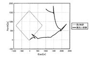
1-4. Simulation Result In order to show the effectiveness of the above position calculation method, the result of a simulation experiment for calculating the position of the moving object will be described. A simulation experiment was performed in which the
図8は、従来の手法を用いたシミュレーション結果を示す。それに対し、図9は、本実施形態の手法を用いたシミュレーション結果を示す。各図において、横軸は東西方向、縦軸は南北方向を示し、単位はメートル[m]である。東西方向“0m”、南北方向“0m”の位置をスタート地点とし、大きく反時計回り方向に1周周回するようなダイヤ型の経路を辿った。ゴール地点はスタート地点と同じである。移動体の真の軌跡を破線で示し、算出した位置の軌跡を実線で示す。 FIG. 8 shows a simulation result using a conventional method. On the other hand, FIG. 9 shows a simulation result using the method of the present embodiment. In each figure, the horizontal axis indicates the east-west direction, the vertical axis indicates the north-south direction, and the unit is meters [m]. The starting point was the east-west direction “0m” and the north-south direction “0m”, and it followed a diamond-shaped route that made one round in a counterclockwise direction. The goal point is the same as the starting point. The true locus of the moving object is indicated by a broken line, and the locus of the calculated position is indicated by a solid line.
図8を見ると、従来の手法を用いた場合は、重大な位置誤差が生じていることがわかる。つまり、ダイヤ型の軌跡に沿って位置が算出されるどころか、スタート直後から東方向に向かって位置が逸れていき、最終的には、ゴール地点から程遠い位置をゴール地点と判定していることがわかる。これは、センサー3の取付姿勢を判定せずに位置算出を行った結果である。つまり、ローカル座標系と移動体座標系とが一致していないにも関わらず、移動体座標系で定義される移動時速度制約条件(第2の制約条件)を適用して位置算出を行ったために、当初から誤った方向に位置が算出され、時間経過に伴って誤差が累積的に増加した結果である。
FIG. 8 shows that a significant positional error occurs when the conventional method is used. In other words, instead of calculating the position along the diamond-shaped trajectory, the position deviates toward the east immediately after the start, and finally the position far from the goal point is determined as the goal point Recognize. This is a result of performing position calculation without determining the mounting posture of the
それに対し、図9を見ると、本実施形態の手法を用いた場合は、ダイヤ型の真の軌跡に沿ったほぼ正確な軌跡が得られていることがわかる。これは、センサー3の取付姿勢を可能な限り正確に判定して、位置算出を行うことができた結果である。つまり、センサー3の取付姿勢を判定した上で、ローカル座標系と移動体座標系とのズレ分を考慮して移動体座標系への座標変換を行い、移動体座標系で定義される移動時速度制約条件を適用して位置算出を行ったため、このような良好な結果が得られたのである。
On the other hand, when FIG. 9 is seen, when the method of this embodiment is used, it turns out that the substantially exact locus | trajectory along the true locus | trajectory of a diamond type is obtained. This is a result of calculating the position by determining the mounting posture of the
2.実施例
次に、上記の姿勢判定方法及び位置算出方法を適用したナビゲーションシステムの実施例について説明する。但し、本発明を適用可能な実施例が以下説明する実施例に限定されるわけではないことは勿論である。
2. Example Next, an example of a navigation system to which the posture determination method and the position calculation method are applied will be described. However, it goes without saying that the embodiments to which the present invention can be applied are not limited to the embodiments described below.
本実施例におけるナビゲーションシステムは、移動体の一種である四輪自動車(以下、単に「自動車」と称す。)に、原理で説明した取付姿勢判定システム(姿勢判定装置)及び位置算出システム(位置算出装置)を適用したカーナビゲーション装置1000が設置されたシステムとして構成される。
The navigation system in this embodiment is a four-wheeled vehicle (hereinafter, simply referred to as “automobile”) that is a kind of mobile body, and includes a mounting posture determination system (posture determination device) and a position calculation system (position calculation) described in principle. Device) to which the
カーナビゲーション装置1000は、自動車に搭載される電子機器であり、加速度センサー3A及びジャイロセンサー3Cを有するセンサーユニットとしてIMU(Inertial Measurement Unit)400を具備している。IMU400は、慣性計測ユニットとして知られるセンサーユニットであり、ローカル座標系で表した加速度ベクトル及び角速度を計測して出力可能に構成されている。
The
カーナビゲーション装置1000は、IMU400の計測結果を利用して慣性航法演算処理を行うことで、絶対座標系での自動車の位置を算出する。本実施例では、絶対座標系としてNED座標系を適用する場合について説明する。つまり、カーナビゲーション装置1000は、NED座標系での自動車の位置を算出する。そして、カーナビゲーション装置1000は、算出位置をプロットしたナビゲーション画面を生成し、当該ナビゲーション画面を表示部300であるディスプレイに表示させる。
The
2−1.機能構成
図10は、カーナビゲーション装置1000の機能構成の一例を示すブロック図である。カーナビゲーション装置1000は、主要な機能構成として、処理部100と、操作部200と、表示部300と、IMU400と、記憶部500とを備えて構成される。
2-1. Functional Configuration FIG. 10 is a block diagram illustrating an example of a functional configuration of the
処理部100は、記憶部500に記憶されているシステムプログラム等の各種プログラムに従ってカーナビゲーション装置1000の各部を統括的に制御する制御装置であり、CPU(Central Processing Unit)等のプロセッサーを有して構成される。処理部100は、IMU400の計測結果を利用した慣性航法演算処理を行って自動車の位置等を算出する。処理部100は、自動車に対するIMU400の姿勢を判定する姿勢判定装置として機能するとともに、自動車の位置を算出する位置算出装置として機能する。
The
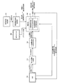
図11は、処理部100に係る機能ブロックを中心に示したブロック図である。処理部100は、慣性航法演算部105と、取付姿勢判定部110と、移動状況判定部160と、速度制約条件設定部170と、LV座標変換行列算出部180と、補正部190とを機能部として有する。
FIG. 11 is a block diagram mainly showing functional blocks related to the
慣性航法演算部105は、IMU400から入力したローカル座標加速度ベクトル及びローカル座標角速度を用いて、慣性航法演算処理を行って自動車のNED座標位置、NED座標速度ベクトル及び絶対姿勢角を算出する。
The inertial
補正部190は、取付姿勢判定部110から入力したIMU400の取付姿勢角と、速度制約条件設定部170から入力した速度制約条件とを用いて、慣性航法演算部105から入力したNED座標位置、NED座標速度ベクトル及び絶対姿勢角を補正する。補正部190は、KF誤差推定部191と、NL座標変換行列193とを機能部として有する。
The
KF誤差推定部191は、カルマンフィルターを利用してNED座標系での慣性航法演算結果に含まれる慣性航法演算誤差を推定する。
The
NL座標変換行列算出部193は、慣性航法演算部105から入力した絶対姿勢角を用いて、NED座標系からローカル座標系への座標変換行列(以下、「NL座標変換行列」と称す。)を算出する。
The NL coordinate transformation
図10の説明に戻り、操作部200は、例えばタッチパネルやボタンスイッチ等により構成される入力装置であり、押下されたキーやボタンの信号を処理部100に出力する。この操作部200の操作により、目的地の入力等の各種指示入力がなされる。
Returning to the description of FIG. 10, the
表示部300は、LCD(Liquid Crystal Display)等により構成され、処理部100から入力される表示信号に基づいた各種表示を行う表示装置である。表示部300には、ナビゲーション画面等が表示される。
The
IMU400は、慣性計測ユニットとして知られるセンサーユニットであり、例えば加速度センサー3A及びジャイロセンサー3Cを有して構成される。
The
記憶部500は、ROM(Read Only Memory)やフラッシュROM、RAM(Random Access Memory)等の記憶装置によって構成され、カーナビゲーション装置1000のシステムプログラムや、ナビゲーション機能等の各種機能を実現するための各種プログラム、データ等を記憶している。また、各種処理の処理中データ、処理結果などを一時的に記憶するワークエリアを有する。
The
2−2.データ構成
図10に示すように、記憶部500には、プログラムとして、処理部100により読み出され、ナビゲーション処理(図12参照)として実行されるナビゲーションプログラム510が記憶されている。ナビゲーションプログラム510は、補正処理(図13参照)として実行される補正プログラム511をサブルーチンとして含む。これらの処理については、フローチャートを用いて詳細に後述する。
2-2. Data Configuration As shown in FIG. 10, the
また、記憶部500には、データとして、速度制約条件520と、IMU計測データ530と、慣性航法演算データ540と、取付姿勢データ550と、座標変換行列データ560と、推定誤差データ570と、補正慣性航法演算データ580とが記憶される。
Further, the
速度制約条件520は、自動車の移動状況に応じた速度の制約条件であり、停止時速度制約条件521と、移動時速度制約条件523とがこれに含まれる。
The
IMU計測データ530は、IMU400の計測結果のデータである。加速度センサー3Aにより計測されたローカル座標加速度ベクトルと、ジャイロセンサー3Cにより計測されたローカル座標角速度とが時系列に記憶される。
The
慣性航法演算データ540は、処理部100がIMU400の計測結果を利用して慣性航法演算処理を行うことで算出したNED座標位置、NED座標速度ベクトル及び絶対姿勢角のデータである。
The inertial
取付姿勢データ550は、処理部100により算出されたIMU400の取付姿勢角が記憶されたデータである。座標変換行列データ560は、処理部100が算出した各種の座標変換行列が記憶されたデータである。
The mounting
推定誤差データ570は、処理部100がKF誤差推定演算を行って推定した慣性航法演算誤差が記憶されたデータである。また、補正慣性航法演算データ580は、処理部100が、慣性航法演算誤差を用いて慣性航法演算結果を補正したデータである。
The estimated
2−3.処理の流れ
図12は、記憶部500に記憶されているナビゲーションプログラム510が処理部100により読み出されて実行されることで、カーナビゲーション装置1000において実行されるナビゲーション処理の流れを示すフローチャートである。以下のナビゲーション処理では、IMU400により計測されたローカル座標加速度ベクトル及びローカル座標角速度が、記憶部500のIMU計測データ530に随時記憶されるものとする。
2-3. Processing Flow FIG. 12 is a flowchart showing the flow of navigation processing executed in the
最初に、処理部100は、初期設定を行う(ステップA1)。例えば、カルマンフィルターで利用する各種パラメーター値の初期設定を行う。また、自動車が停止している状態であるとして停止時速度制約条件521を「ON」に設定し、移動時速度制約条件523を「OFF」に設定する。
First, the
次いで、慣性航法演算部105が、慣性航法演算処理を開始する(ステップA3)。つまり、慣性航法演算部105は、IMU計測データ530に記憶されているIMU400の計測データを利用して慣性航法演算処理を行う。そして、その結果を慣性航法演算データ540として記憶部500に記憶させる。
Next, the inertial
その後、補正部190は、記憶部500に記憶されている補正プログラム511に従って補正処理を開始する(ステップA5)。
Thereafter, the
図13は、補正処理の流れを示すフローチャートである。
先ず、KF誤差推定部191は、移動時速度制約条件523が「ON」に設定されているか否かを判定する(ステップB1)。そして、移動時速度制約条件523が「ON」に設定されていると判定した場合は(ステップB1;Yes)、NL座標変換行列算出部193が、最新の絶対姿勢角を用いてNL座標変換行列を算出し、記憶部500の座標変換行列データ560に記憶させる(ステップB3)。
FIG. 13 is a flowchart showing the flow of the correction process.
First, the KF
次いで、KF誤差推定部191は、ステップB3で算出したNL座標変換行列を用いて、NED座標速度ベクトルを移動体座標速度ベクトルに変換する(ステップB5)。そして、KF誤差推定部191は、移動時制約速度ベクトルと、移動体座標速度ベクトルとの差を算出して、移動時観測ベクトルとする(ステップB7)。
Next, the
その後、KF誤差推定部191は、KF誤差推定処理を行う(ステップB9)。すなわち、ステップB7で設定した移動時観測ベクトルを観測情報として、予測演算及び補正演算を行って慣性航法演算誤差を推定する。そして、KF誤差推定部191は、推定した慣性航法演算誤差を用いて慣性航法演算結果を補正し、その結果を記憶部500の補正慣性航法演算データ580に記憶させた後(ステップB11)、ステップB1に戻る。
Thereafter, the KF
また、ステップB1において移動時速度制約条件523が「ON」に設定されていないと判定した場合は(ステップB1;No)、KF誤差推定部191は、停止時速度制約条件521が「ON」に設定されているか否かを判定する(ステップB13)。そして、「ON」に設定されていると判定したならば(ステップB13;Yes)、KF誤差推定部191は、停止時制約速度ベクトルと、NED座標速度ベクトルとの差を算出して、停止時観測ベクトルとする(ステップB15)。
If it is determined in step B1 that the moving
その後、KF誤差推定部191は、KF誤差推定処理を行う(ステップB17)。すなわち、ステップB15で設定した停止時観測ベクトルを観測情報として、予測演算及び補正演算を行って慣性航法演算誤差を推定する。そして、KF誤差推定部191は、推定した慣性航法演算誤差を用いて慣性航法演算結果を補正し、その結果を記憶部500の補正慣性航法演算データ580に記憶させた後(ステップB19)、ステップB1に戻る。
Thereafter, the KF
また、ステップB13において停止時速度制約条件521が「ON」に設定されていないと判定した場合は(ステップB13;No)、補正部190は、ステップB1に戻る。
If it is determined in step B13 that the stop
図12の説明に戻り、ステップA5において補正処理を開始したならば、移動状況判定部160は、自動車の移動状況を判定する(ステップA7)。そして、処理部100は、自動車が停止状態から移動を開始したか否かを判定する(ステップA9)。例えば、自動車のブレーキ制御の解除信号を外部入力したり、車速情報を外部入力する等して判定する。
Returning to the description of FIG. 12, if the correction process is started in step A5, the movement
自動車が移動を開始したと判定した場合は(ステップA9;Yes)、速度制約条件設定部170は、停止時速度制約条件521を「OFF」に設定する(ステップA11)。そして、処理部100は、所定の取付姿勢判定発動条件が成立したか否かを判定する(ステップA13)。取付姿勢判定発動条件は、原理でも説明したように、取付姿勢の判定精度を保証するために定める条件である。例えば、移動体の停止が解除された後、移動体の速度又は加速度が所定の閾値に達することを発動条件として定めておくと好適である。
When it is determined that the vehicle has started moving (step A9; Yes), the speed constraint
ステップA13において、未だ取付姿勢判定発動条件が成立していないと判定した場合は(ステップA13;No)、処理部100は、ステップA27へと処理を移行する。取付姿勢判定発動条件が成立したと判定した場合は(ステップA13;Yes)、取付姿勢判定部110は、取付姿勢判定処理を行う(ステップA15)。つまり、最新のローカル座標速度ベクトルを用いて、式(2)及び式(3)に従って取付姿勢角を算出し、記憶部500の取付姿勢データ550を更新する。
If it is determined in step A13 that the mounting posture determination trigger condition has not yet been satisfied (step A13; No), the
次いで、処理部100は、ステップA15で算出した取付姿勢角を用いてLV座標変換行列を算出し、記憶部500の座標変換行列データ560を更新する(ステップA17)。そして、処理部100は、移動時速度制約条件523を「ON」に設定する(ステップA19)。
Next, the
一方、ステップA9において自動車が移動を開始したことを検知しなかった場合は(ステップA9;No)、処理部100は、自動車が移動状態から停止状態に変化したか否かを判定する(ステップA21)。停止状態に変化しなかったと判定した場合は(ステップA21;No)、処理部100は、ステップA27に移行する。
On the other hand, when it is not detected in step A9 that the automobile has started moving (step A9; No), the
また、自動車が移動状態から停止状態に変化したと判定した場合は(ステップA21;Yes)、処理部100は、移動時速度制約条件523を「OFF」に設定するとともに(ステップA23)、停止時速度制約条件521を「ON」に設定する(ステップA25)。そして、処理部100は、ステップA27に移行する。
When it is determined that the vehicle has changed from the moving state to the stopped state (step A21; Yes), the
処理部100は、位置の出力タイミングであるか否かを判定し(ステップA27)、出力タイミングではないと判定した場合は(ステップA27;No)、ステップA31へと処理を移行する。また、出力タイミングであると判定した場合は(ステップA27;Yes)、処理部100は、最新の補正位置を出力する(ステップA29)。つまり、最新の補正位置に対してマップマッチング処理等を行い、表示部300のナビゲーション画面を更新する。
The
次いで、処理部100は、ナビゲーション処理を終了するか否かを判定する(ステップA31)。例えば、操作部200を介してユーザーによりナビゲーションの終了指示操作がなされた場合に、ナビゲーション処理を終了すると判定する。そして、まだ処理を終了しないと判定した場合は(ステップA31;No)、処理部100は、ステップA7に戻る。また、処理を終了すると判定した場合は(ステップA31;Yes)、処理部100は、ナビゲーション処理を終了する。
Next, the
2−4.実験結果
上記のカーナビゲーション装置1000を自動車に搭載し、実際に自動車を走行させて位置を算出する実験を行った。具体的には、上記のナビゲーション処理に従って自動車の位置を算出し、その位置をプロットする実験を行った。
2-4. Experimental Results An experiment was carried out in which the
図14は、従来のカーナビゲーション装置1000による実験結果を示す。それに対し、図15は、本実施例のカーナビゲーション装置1000による実験結果を示す。但し、何れの場合もマップマッチング機能はオフとしている。図の見方は、図8及び図9のシミュレーション結果と同じであるが、実際に走行実験を行った結果であるため、経路が異なっている。東西方向“0m”、南北方向“0m”の位置をスタート地点とし、東方向“12000m”、南方向“10000m”の近傍位置をゴール地点として、スタート地点からゴール地点まで自動車を実際に走行させた。
FIG. 14 shows a result of an experiment performed by the conventional
この結果を見ると、図14の従来のカーナビゲーション装置1000による実験結果では、図8のシミュレーション結果と同様に、スタート直後から誤った方向に位置が算出され、最終的には、ゴール地点から程遠い位置をゴール地点と判定している。それに対し、図15の本実施例のカーナビゲーション装置1000による実験結果では、図9のシミュレーション結果と同様に、ほぼ真の軌跡に沿った正確な軌跡が得られていることがわかる。これにより、実環境においても、本実施形態の位置算出方法は有効であることが示された。
Looking at this result, in the experimental result by the conventional
3.作用効果
本実施形態によれば、移動体に設置されたセンサー3により移動ベクトルが計測される。そして、移動体が移動を開始した際にセンサー3が計測した移動ベクトルを用いて、移動体に対するセンサー3の姿勢が判定される。
3. Effects According to the present embodiment, the movement vector is measured by the
第1の取付姿勢判定システム1Aでは、ローカル座標速度ベクトル算出部5が、加速度センサー3Aが計測したローカル座標加速度ベクトルを用いてローカル座標速度ベクトルを算出する。そして、取付姿勢判定部10が、移動体が移動を開始した際のローカル座標速度ベクトルを用いて、加速度センサー3Aの取付姿勢のうちのピッチ成分及びヨー成分を判定する。
In the first mounting
また、第2の取付姿勢判定システム1Bでは、LA座標変換行列算出部20が、姿勢センサー3Bが計測した絶対座標系で表したセンサー3の向き(絶対姿勢)を用いて、ローカル座標系から絶対座標系への座標変換行列(LA座標変換行列)を算出する。そして、絶対座標加速度ベクトル算出部30が、加速度センサー3Aが計測したローカル座標加速度ベクトルを、LA座標変換行列を用いて絶対座標加速度ベクトルに座標変換する。さらに、絶対座標速度ベクトル算出部40は、絶対座標加速度ベクトルを用いて絶対座標速度ベクトルを算出する。取付姿勢判定部10は、姿勢センサー3Bが計測した絶対座標系で表したセンサー3の向きを用いて絶対座標系からローカル座標系への座標変換行列(AL座標変換行列)を算出し、当該AL座標変換行列と、絶対座標速度ベクトルとを用いて、加速度センサー3Aの取付姿勢のうちのピッチ成分及びヨー成分を判定する。
Further, in the second mounting
また、移動体が停止している際には、センサー3の計測結果を補償するための補償演算を行う。例えば、移動体が停止している場合は、移動体の速度ベクトルの各成分はゼロであるとする制約条件(第1の制約条件)を用いて、センサー3の計測結果を補償する。これにより、移動体の停止中は、センサー3の計測結果に含まれる誤差を低減させることができる。誤差が低減された状態で移動体が移動を開始しても、それほど時間が経過していなければ、移動体の速度ベクトルの誤差は抑制されているはずである。そのため、移動体が移動を開始した際の速度ベクトルを利用することで、移動体に対するセンサー3の相対的な姿勢を正しく判定することができる。
Further, when the moving body is stopped, a compensation calculation for compensating the measurement result of the
また、第1の位置算出システム2Aでは、第1の慣性航法システム4Aの慣性航法演算結果(絶対座標位置、絶対座標速度ベクトル及び絶対姿勢角)が、補正部90によって補正される。補正部90は、取付姿勢判定部10により判定された第1の慣性航法システム4Aの取付姿勢と、速度制約条件設定部70により設定された停止時速度制約条件(第1の制約条件)又は移動時速度制約条件(第2の制約条件)と、LV座標変換行列算出部80により算出されたLV座標変換行列とを用いて、所定の誤差推定演算を行って慣性航法演算誤差を推定する。そして、推定した慣性航法演算誤差を用いて慣性航法演算結果を補正する。また、第2の位置算出システム2Bにおいても同様に、第2の慣性航法システム4Bの慣性航法演算結果(絶対座標位置、絶対座標速度ベクトル及び絶対姿勢角)が、補正部90によって補正される。
In the first
このように、第1又は第2の取付姿勢判定方法を用いて判定したセンサー3の取付姿勢と、センサー3が計測した移動ベクトル(加速度ベクトルや速度ベクトル)とを用いることで、ローカル座標系と移動体座標系とのズレ分を考慮し、この2種類の座標系の座標変換を適切に行って、移動体の位置をより正確に算出することができる。
In this way, by using the mounting posture of the
4.変形例
本発明を適用可能な実施例は、上記の実施例に限定されることなく、本発明の趣旨を逸脱しない範囲で適宜変更可能であることは勿論である。以下、変形例について説明するが、上記の実施例と同一の構成要素については同一の符号を付して説明を省略し、上記の実施例とは異なる部分を中心に説明する。
4). Modifications Embodiments to which the present invention can be applied are not limited to the above-described embodiments, and can be changed as appropriate without departing from the spirit of the present invention. Hereinafter, although a modification is demonstrated, the same code | symbol is attached | subjected about the component same as said Example, description is abbreviate | omitted, and it demonstrates centering on a different part from said Example.
4−1.進行方向切替対応ロジック
上記の実施形態では、移動体が移動を開始した際に求めたLV座標変換行列を用いて位置算出を行うものとして説明した。しかし、移動体は必ずしも進行方向前方にのみ移動するとは限らない。例えば、移動体が四輪自動車であるならば、四輪自動車は前方に進行するに限らず、後方に進行する(バックする)場合もあり得る。
4-1. Travel Direction Switching Correspondence Logic In the above embodiment, the position calculation is described using the LV coordinate transformation matrix obtained when the moving body starts moving. However, the moving body does not always move only forward in the traveling direction. For example, if the moving body is a four-wheeled vehicle, the four-wheeled vehicle may not only travel forward but also travel backward (back).
従って、移動体の進行方向が前進と後進とで切り替わる場合、進行方向の変化の前後で同じLV座標変換行列を用いて計算を行ったのでは、移動体の速度や位置が適切に求まらないことが想定される。なぜならば、本実施形態の手法では、移動体が移動を開始した際の移動体の移動方向に対する移動ベクトルを用いてセンサー3の取付姿勢を判定するため、移動体の移動方向が逆転してしまうと、取付姿勢と移動方向との間で辻褄が合わなくなるためである。
Therefore, when the moving direction of the moving object is switched between forward and reverse, if the calculation is performed using the same LV coordinate transformation matrix before and after the change of the moving direction, the speed and position of the moving object can be obtained appropriately. Not expected. This is because, in the method of this embodiment, since the mounting posture of the
上記の問題に鑑み、次のような進行方向切替対応ロジックを適用すると好適である。具体的には、例えば移動体座標系での移動体の速度ベクトルに基づいて、移動体の移動方向が逆転したか否かを判定する。そして、移動体の移動方向が逆転した場合に、移動開始時に求めて記憶しておいたLV座標変換行列を180°回転させて更新し、更新後のLV座標変換行列を用いて計算を行う。 In view of the above problems, it is preferable to apply the following traveling direction switching correspondence logic. Specifically, for example, it is determined whether or not the moving direction of the moving body is reversed based on the velocity vector of the moving body in the moving body coordinate system. Then, when the moving direction of the moving body is reversed, the LV coordinate transformation matrix obtained and stored at the start of the movement is updated by rotating 180 °, and calculation is performed using the updated LV coordinate transformation matrix.
図16は、この場合に、実施例のカーナビゲーション装置1000が図12のナビゲーション処理に代えて実行する第2のナビゲーション処理の流れを示すフローチャートである。
FIG. 16 is a flowchart showing a flow of a second navigation process executed in this case by the
第2のナビゲーション処理では、処理部100は、ステップA19又はステップA25の後、移動体座標系のロール軸(R軸)の速度成分の正負の符号が逆転したか否かを判定する(ステップC25)。符号が逆転していない場合は(ステップC25;No)、自動車の移動方向は変化していないものと判断し、ステップA27に移行する。
In the second navigation process, the
それに対し、正負の符号が逆転している場合は(ステップC25;Yes)、処理部100は、自動車の移動方向が変化したものと判断し、座標変換行列データ560に記憶されている最新のLV座標変換行列を180°回転させて、座標変換行列データ560を更新する(ステップC26)。そして、処理部100は、ステップA27に移行する。
On the other hand, when the sign of the sign is reversed (step C25; Yes), the
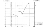
図17及び図18は、上記の進行方向切替対応ロジックの有効性を示す実験結果である。図17は、進行方向切替対応ロジックを適用しない場合の実験結果である。それに対し、図18は、進行方向切替対応ロジックを適用した場合の実験結果である。車の進行方向前方(前進方向)とセンサー3のx軸正方向とが一致するようにセンサー3を設置した。つまり、この場合のセンサー3の取付姿勢角は「0°」である。
FIG. 17 and FIG. 18 are experimental results showing the effectiveness of the traveling direction switching correspondence logic. FIG. 17 shows experimental results when the traveling direction switching logic is not applied. On the other hand, FIG. 18 shows an experimental result when the traveling direction switching correspondence logic is applied. The
自動車を時刻「t0」〜「t1」までの期間停止させた。そして、時刻「t1」においてバックで移動開始し、時刻「t2」において自動車を一旦停止させて、今度は自動車を前方に移動させた。各図において、横軸は時間軸を示し、縦軸は自動車のロール軸速度(単位は[m/s])及びセンサー3の取付姿勢角(単位は[°])を示す。また、判定されたセンサー3の取付姿勢角を太実線で示し、算出された自動車のロール軸速度を細実線で示す。
The automobile was stopped for a period from time “t0” to “t1”. Then, at time “t1”, the vehicle started to move back, and at time “t2”, the automobile was temporarily stopped, and this time, the automobile was moved forward. In each figure, the horizontal axis indicates the time axis, and the vertical axis indicates the roll axis speed (unit: [m / s]) of the automobile and the mounting posture angle (unit: [°]) of the
これらの図を見ると、時刻「t0」〜「t1」までの間は、ロール軸速度はゼロとなっている。そして、時刻「t1」において自動車がバックを開始するとロール軸速度は負の値となり、時刻「t2」までは徐々に減少していく。 As can be seen from these figures, the roll shaft speed is zero between the times “t0” to “t1”. When the vehicle starts to back at time “t1”, the roll axis speed becomes a negative value and gradually decreases until time “t2”.
その後、時刻「t2」においてロール軸速度の絶対値が所定の閾値を超えると、取付姿勢判定発動条件が成立する(図16のステップA13;Yes)。これにより、センサー3の取付姿勢が判定される(図16のステップA15)。この場合、取付姿勢判定部10は、自動車が後進(バック)した方向を自動車の移動方向と認識して取付姿勢を判定するため、実際にはセンサー3の取付姿勢角は「0°」であるのに、取付姿勢角を「180°」と判定してしまう。
Thereafter, when the absolute value of the roll shaft speed exceeds a predetermined threshold at time “t2”, the attachment posture determination trigger condition is satisfied (step A13 in FIG. 16; Yes). Thereby, the mounting posture of the
この場合、取付姿勢角を「180°」としてLV座標変換行列を算出し(図16のステップA17)、当該LV座標変換行列を用いて計算を行うため、自動車のロール軸速度は正の値として算出されてしまう。自動車はバックで移動しているため、実際にはロール軸速度は負の値である。 In this case, the LV coordinate transformation matrix is calculated with the mounting attitude angle set to “180 °” (step A17 in FIG. 16), and the calculation is performed using the LV coordinate transformation matrix. It will be calculated. Since the automobile is moving in the back, the roll axis speed is actually a negative value.
進行方向切替対応ロジックを適用しない場合は、図17に示すように、時刻「t3」において自動車が前方に移動を開始しても、センサー3の取付姿勢角が「180°」であると認識したまま計算を行うため、ロール軸速度の符号は変化しない。そのため、正の値として算出されるべきロール軸速度は負の値として算出され、自動車が前方に加速するにつれて、ロール軸速度は負の方向に増大してしまっている。
When the traveling direction switching correspondence logic is not applied, as shown in FIG. 17, even when the automobile starts moving forward at time “t3”, it is recognized that the mounting posture angle of the
それに対し、進行方向切替対応ロジックを適用した場合は、図18に示すように、時刻「t3」において自動車が前方に移動を開始したことを検知すると(図16のステップC25;Yes)、取付姿勢角を「180°」として算出したLV座標変換行列を反転させて更新する(図16のステップC26)。そして、反転後のLV座標変換行列を用いて計算を行うため、算出されるロール軸速度の符号は負から正に変化する。そして、自動車が前方に加速したことで、ロール軸速度は正の方向に増大していく。このように、進行方向切替対応ロジックを適用することで、移動体の進行方向の変化に適切に対応することができる。 On the other hand, when the traveling direction switching correspondence logic is applied, as shown in FIG. 18, when it is detected that the vehicle starts moving forward at time “t3” (step C25 in FIG. 16; Yes), the mounting posture The LV coordinate transformation matrix calculated with the angle of “180 °” is inverted and updated (step C26 in FIG. 16). Since the calculation is performed using the inverted LV coordinate transformation matrix, the sign of the calculated roll axis speed changes from negative to positive. Then, as the automobile accelerates forward, the roll axis speed increases in the positive direction. In this way, by applying the traveling direction switching support logic, it is possible to appropriately cope with a change in the traveling direction of the moving body.
4−2.補正部の補正方法
上記の実施形態では、慣性航法演算結果を補正する手法としてカルマンフィルターを例に挙げて説明したが、補正方法はこれに限られない。例えば、速度制約条件設定部70により設定された速度制約条件に含まれる制約速度ベクトルと、慣性航法演算で得られた速度ベクトルとの平均化処理を行って速度ベクトルを補正することとしてもよい。
4-2. Correction Method of Correction Unit In the above embodiment, the Kalman filter has been described as an example of a method for correcting the inertial navigation calculation result, but the correction method is not limited to this. For example, the speed vector may be corrected by averaging the restricted speed vector included in the speed restriction condition set by the speed restriction
また、車速検出システムにより計測された移動体の速度や、磁気センサー等の方位センサーにより計測された移動体の向きを用いて、慣性航法演算で得られた速度ベクトルを補正することとしてもよい。例えば、速度ベクトルの大きさについて、慣性航法演算で得られた速度ベクトルの大きさと、車速検出システムにより計測された速度との平均化処理を行うこととしてもよい。また、速度ベクトルの向きについて、慣性航法演算で得られた速度ベクトルの向きと、方位センサーにより計測された移動体の向きとの平均化処理を行うこととしてもよい。 Further, the velocity vector obtained by the inertial navigation calculation may be corrected using the velocity of the moving object measured by the vehicle speed detection system and the direction of the moving object measured by the azimuth sensor such as a magnetic sensor. For example, the speed vector magnitude may be averaged between the speed vector magnitude obtained by the inertial navigation calculation and the speed measured by the vehicle speed detection system. Further, with respect to the direction of the velocity vector, it is possible to perform an averaging process between the direction of the velocity vector obtained by the inertial navigation calculation and the direction of the moving body measured by the direction sensor.
平均化処理は、単純な算術平均や幾何平均を適用してもよいし、加重平均を適用してもよい。慣性航法演算結果を信用して速度ベクトルを補正するのであれば、慣性航法演算結果の重みを車速検出システムや方位センサーの計測結果の重みよりも高くして加重平均すればよい。逆に、車速検出システムや方位センサーの計測結果を信用して速度ベクトルを補正するのであれば、慣性航法演算結果の重みを車速検出システムや方位センサーの計測結果の重みよりも低くして加重平均すればよい。なお、これらの手法以外にも、補正部の補正手法としては任意の手法を適用可能である。 For the averaging process, a simple arithmetic average or geometric average may be applied, or a weighted average may be applied. If the inertial navigation calculation result is trusted and the velocity vector is corrected, the weight of the inertial navigation calculation result may be set higher than the weight of the measurement result of the vehicle speed detection system or the direction sensor, and the weighted average may be performed. Conversely, if the speed vector is corrected by trusting the measurement result of the vehicle speed detection system or direction sensor, the weighted average is calculated by making the weight of the inertial navigation calculation result lower than the weight of the measurement result of the vehicle speed detection system or direction sensor. do it. In addition to these methods, any method can be applied as the correction method of the correction unit.
4−3.処理の主体
上記の実施例では、電子機器にIMU400が搭載され、IMU400の計測結果に基づいて、電子機器の処理部が慣性航法演算処理を行うものとして説明した。しかし、電子機器にINSを搭載することとし、INSの処理部が慣性航法演算処理を行うこととしてもよい。この場合、電子機器の処理部は、INSから出力される慣性航法演算結果に含まれる誤差(慣性航法演算誤差)を推定する処理を行う。そして、推定した慣性航法演算誤差を用いて、INSから入力した慣性航法演算結果を補正する。
4-3. Processing Subject In the above embodiment, the
また、電子機器にGPS(Global Positioning System)等の衛星測位システムを適用したセンサーユニットを搭載することとし、このセンサーユニットの計測結果を利用して、慣性航法演算結果を補正することとしてもよい。 In addition, a sensor unit to which a satellite positioning system such as GPS (Global Positioning System) is applied may be mounted on the electronic device, and the inertial navigation calculation result may be corrected using the measurement result of the sensor unit.
図19は、この場合における電子機器の構成を示す図であり、処理部100に係る機能ブロックを中心に示したものである。図19の電子機器では、図11のIMU400の代わりにINS700が搭載され、さらにGPSユニット800が搭載されている。この場合、処理部100は慣性航法演算処理を行わないため、図11における慣性航法演算部105は削除されている。
FIG. 19 is a diagram illustrating a configuration of the electronic device in this case, and mainly illustrates functional blocks related to the
取付姿勢判定部110は、INS700から入力したローカル座標速度ベクトルを用いて、INS700の取付姿勢を判定する。補正部190のKF誤差推定部191は、速度制約条件設定部170から入力した速度制約条件の他に、GPSユニット800から入力したメジャメント情報を観測情報として、INS700の慣性航法演算結果に含まれる慣性航法演算誤差を推定する。
The mounting
メジャメント情報は、GPS衛星から受信したGPS衛星信号に係る各種の諸量である。例えば、GPS衛星信号のキャリア位相やコード位相、ドップラー周波数、擬似距離、擬似距離の変化率(レンジレート)といった諸量がメジャメント情報に含まれる。なお、GPSのメジャメント情報を観測情報として慣性航法演算誤差を推定する手法については従来公知であるため、数式等を用いた説明は省略する。 The measurement information is various amounts related to the GPS satellite signal received from the GPS satellite. For example, various amounts such as the carrier phase and code phase of the GPS satellite signal, the Doppler frequency, the pseudorange, and the change rate (range rate) of the pseudorange are included in the measurement information. Since a technique for estimating inertial navigation calculation errors using GPS measurement information as observation information is known in the art, description using mathematical formulas and the like is omitted.
4−4.姿勢判定タイミング
上記の実施形態では、移動体が停止した後に移動を開始する度に、センサー3の取付姿勢を判定するものとして説明した。しかし、姿勢判定タイミングは適宜設定可能である。例えば、センサー3が移動体に設置された後、移動体の初回の移動開始タイミングにのみセンサー3の取付姿勢を判定することとしてもよい。この場合は、初回以降は取付姿勢判定を行わず、初回に判定した取付姿勢を用いて処理を行うようにすればよい。
4-4. Posture determination timing In the above-described embodiment, the mounting posture of the
4−5.姿勢判定の成分
上記の実施形態では、移動体に対するセンサー3の取付姿勢のピッチ成分及びヨー成分の両方を判定するものとして説明したが、ピッチ成分及びヨー成分の何れか一方のみを判定することとしてもよいのは勿論である。
4-5. In the above-described embodiment, it is described that both the pitch component and the yaw component of the mounting posture of the
4−6.設置ずれの誤差
上記の実施形態では、移動中はセンサー3の取付姿勢に変化が生じないことを前提としていた。しかし、移動中の振動等によってセンサー3の取付姿勢の変化、すなわち設置ずれが生じる可能性がある。そこで、式(6)の状態ベクトルに設置ずれによる誤差角度の成分を追加し、KF誤差推定部191が移動時速度制約条件521を「ON」として求めた移動時観測ベクトルを用いてKF誤差推定処理を行って(ステップB9)、設置ずれの誤差角度を推定することとしてもよい。このようにすることで、移動中にセンサー3の取付姿勢が変化した場合であっても、図12や図16のステップA15の取付姿勢判定処理で判定された取付姿勢を随時補正することが可能となる。
4-6. In the above embodiment, it is assumed that the mounting posture of the
4−7.取付姿勢判定処理の変形例
図3等を用いて説明した取付姿勢の判定では、IMU400が計測するローカル座標加速度ベクトルにバイアス誤差がのっている場合、算出されるAL座標変換行列にもバイアス誤差が含まれるため、正確な姿勢の判定ができない場合が考えられる。そこで、次のようにしてもよい。
4-7. Modification Example of Mounting Posture Determination Processing In the determination of the mounting posture described with reference to FIG. 3 and the like, if a bias error is added to the local coordinate acceleration vector measured by the
すなわち、図20に示すように、図11に示した処理部100の機能ブロックにおいて、IMU400が計測したローカル座標加速度ベクトル及びローカル座標角速度を取付姿勢判定部110へ入力するようにする。そして、取付姿勢判定部110(処理部100)は、図21に示す第2の取付姿勢判定処理を実行する。
That is, as shown in FIG. 20, in the functional block of the
図21において、処理部100は、自動車が停止しているか否かを判定する(ステップD1)。停止している場合には、ローカル座標速度ベクトルをゼロリセットするとともに(ステップD3)、IMU400で計測されているローカル座標角速度及びローカル座標加速度ベクトルを停止時の計測データとして取得・更新する(ステップD5)。このときのローカル座標角速度をローカル座標停止時角速度Ωsと称し、ローカル座標加速度をローカル座標停止時加速度αsと称する。
In FIG. 21, the
停止が継続している間、ステップD3〜D5を繰り返し行い、停止が解除され、自動車が移動を開始したと判定された場合は(ステップD7:YES)、次の処理に移行する。ここで、移動中のIMU400で計測されているローカル座標角速度を符号Ωmとし、ローカル座標加速度を符号αmとして説明する。まず、ローカル座標の回転情報を算出する(ステップD9)。具体的には、ローカル座標停止時角速度Ωsに対するローカル座標角速度Ωmの時間変化(時間微分)を積算し、継ぎ足していく。この値は、停止時のローカル座標系に対する座標系自体の回転、すなわちローカル座標回転情報を示す。
While the stop is continued, steps D3 to D5 are repeated, and when the stop is released and it is determined that the automobile has started moving (step D7: YES), the process proceeds to the next process. Here, the local coordinate angular velocity measured by the moving
次いで、ローカル座標停止時加速度ベクトルαsを、ステップD9で算出したローカル座標回転情報を用いて逆変換することで、IMU400で計測されているローカル座標系における加速度αmsに変換する(ステップD11)。そして、IMU400で計測されているローカル座標加速度αmと変換した加速度αmsとの差を取ることで、当該時点の加速度αfを求める(ステップD13)。変換した加速度αmsと、IMU400で計測されているローカル座標系における加速度αmとは、同じローカル座標系上での加速度である。そして、もしも両者の加速度ベクトルにバイアス誤差がのっていたとしても、その差を求める結果、バイアス誤差は相殺することになる。また、重力加速度も相殺される。そのため、IMU400で計測されているローカル座標系における自動車自体の純粋な加速度に係るベクトルαfが得られる。
Next, the local coordinate stop acceleration vector αs is inversely converted using the local coordinate rotation information calculated in step D9, thereby converting the acceleration vector αs into the acceleration αms in the local coordinate system measured by the IMU 400 (step D11). Then, by obtaining the difference between the local coordinate acceleration αm measured by the
次いで、得られた加速度ベクトルαfを用いて、ローカル座標速度ベクトルを更新する(ステップD15)。更新が初回の場合は、ステップD3でリセットしたローカル座標速度ベクトルが初めて更新されるため、停止時のローカル座標系における移動開始直後の速度ベクトルが得られる。以降、取付姿勢の判定タイミングが到来するまでステップD9〜D15の処理を繰り返す(ステップD17)。取付姿勢の判定タイミングは、図12のステップA13の取付姿勢判定発動条件の成否で判定すると好適である。
姿勢判定の判定タイミングが到来した場合、最新のローカル座標速度ベクトルをもとに、上述の式(2)及び式(3)を用いて取付姿勢を判定する(ステップD19)。
Next, the local coordinate velocity vector is updated using the obtained acceleration vector αf (step D15). When updating is performed for the first time, the local coordinate velocity vector reset in step D3 is updated for the first time, so that a velocity vector immediately after the start of movement in the local coordinate system at the time of stop is obtained. Thereafter, steps D9 to D15 are repeated until the attachment posture determination timing comes (step D17). The attachment posture determination timing is preferably determined based on the success or failure of the attachment posture determination trigger condition in step A13 in FIG.
When the determination timing of the posture determination has arrived, the mounting posture is determined using the above-described equations (2) and (3) based on the latest local coordinate velocity vector (step D19).
以上の第2の取付姿勢判定処理は、ナビゲーション処理の実行中に並行して実行することとするとよい。例えば図12や図16のステップA3とA5の間に、第2の取付姿勢判定処理の実行を開始するステップを加える。この場合、第2の取付姿勢判定処理は、図12や図16のステップA15で実行される取付姿勢判定処理の代わりの処理となるため、ステップA15では取付姿勢判定処理を行わずともよい。 The above-described second mounting posture determination process may be executed in parallel while the navigation process is being executed. For example, a step of starting execution of the second attachment posture determination process is added between steps A3 and A5 of FIGS. In this case, since the second mounting posture determination process is a process instead of the mounting posture determination process executed in step A15 of FIGS. 12 and 16, the mounting posture determination process may not be performed in step A15.
また、第2の取付姿勢判定処理の効果確認試験を行った。ローカル座標系のx軸及びz軸にバイアス誤差を生じさせた場合の従来の取付姿勢判定処理の判定結果と、第2の取付姿勢判定処理の判定結果とを比較した。x軸に+1[mG]、z軸に−1[mG]のバイアス誤差を生じさせた第1試験では、従来の取付姿勢判定処理ではヨー角の誤差が−3.40[deg]、ピッチ角の誤差が+5.53[deg]であった。一方、第2の取付姿勢判定処理ではヨー角の誤差が+0.06[deg]、ピッチ角の誤差が−0.01[deg]であった。また、x軸に+100[mG]、z軸に−100[mG]のバイアス誤差を生じさせた第2試験では、従来の取付姿勢判定処理ではヨー角の誤差が+74.26[deg]、ピッチ角の誤差が−34.30[deg]であった。一方、第2の取付姿勢判定処理ではヨー角の誤差が+0.05[deg]、ピッチ角の誤差が+0.00[deg]であった。 Moreover, the effect confirmation test of the 2nd attachment attitude | position determination process was done. The determination result of the conventional attachment posture determination process when a bias error is generated in the x-axis and the z-axis of the local coordinate system was compared with the determination result of the second attachment posture determination process. In the first test in which a bias error of +1 [mG] is generated on the x axis and −1 [mG] is generated on the z axis, the yaw angle error is −3.40 [deg] and the pitch angle in the conventional mounting posture determination process The error was +5.53 [deg]. On the other hand, in the second mounting posture determination process, the error in the yaw angle was +0.06 [deg], and the error in the pitch angle was -0.01 [deg]. In the second test in which a bias error of +100 [mG] is generated on the x axis and −100 [mG] is generated on the z axis, the error of the yaw angle is +74.26 [deg] and the pitch is determined in the conventional mounting posture determination process. The angle error was −34.30 [deg]. On the other hand, in the second mounting posture determination process, the yaw angle error was +0.05 [deg], and the pitch angle error was +0.00 [deg].
4−8.移動体
本発明は種々の移動体に適用可能である。好適な適用例は四輪自動車であるが、例えば移動時には縦方向や横方向に移動しないといった移動方向に関する制約を課すことができるのであれば、二輪自動車や自転車、電車、船、人間といった移動体にも本発明を適用可能である。
4-8. Mobile Object The present invention can be applied to various mobile objects. A suitable application example is a four-wheeled vehicle, but if it can impose restrictions on the moving direction, for example, it does not move in the vertical or horizontal direction when moving, a moving object such as a two-wheeled vehicle, bicycle, train, ship, or human The present invention can also be applied to.
4−9.電子機器
上記の実施例では、カーナビゲーション装置に本発明を適用した場合を例に挙げて説明したが、本発明を適用可能な電子機器はこれに限られるわけではない。例えば、携帯型ナビゲーション装置(ポータブルナビ)や携帯型電話機、パソコン、PDAといった他の電子機器にも本発明を適用可能である。
4-9. In the above embodiment, the case where the present invention is applied to a car navigation apparatus has been described as an example, but the electronic apparatus to which the present invention can be applied is not limited thereto. For example, the present invention can be applied to other electronic devices such as a portable navigation device (portable navigation), a portable phone, a personal computer, and a PDA.
1A 第1の取付姿勢判定システム、 1B 第2の取付姿勢判定システム、 2A 第1の位置算出システム、 2B 第2の位置算出システム、 3 センサー、 3A 加速度センサー、 3B 姿勢センサー、 3C ジャイロセンサー、 4A 第1の慣性航法システム、 4B 第2の慣性航法システム、 5 ローカル座標速度ベクトル算出部、 10 取付姿勢判定部、 15 絶対姿勢判定部、 20 LA座標変換行列算出部、 30 絶対座標加速度ベクトル算出部、 40 絶対座標速度ベクトル算出部、 50 絶対座標位置算出部、 60 移動状況判定部、 70 速度制約条件設定部、 80 LV座標変換行列算出部、 90 補正部
1A First mounting posture determination system, 1B Second mounting posture determination system, 2A First position calculation system, 2B Second position calculation system, 3 sensor, 3A acceleration sensor, 3B posture sensor, 3C gyro sensor, 4A 1st inertial navigation system, 4B 2nd inertial navigation system, 5 local coordinate velocity vector calculation unit, 10 mounting posture determination unit, 15 absolute posture determination unit, 20 LA coordinate transformation matrix calculation unit, 30 absolute coordinate acceleration
Claims (9)
前記移動体が移動を開始した際に前記センサーが計測した前記移動ベクトルを用いて、前記移動体に対する前記センサーの姿勢を判定することと、
を含む姿勢判定方法。 A sensor for measuring a movement vector installed on a moving body measures the movement vector;
Using the movement vector measured by the sensor when the moving body starts moving, determining the attitude of the sensor relative to the moving body;
Posture determination method including
を更に含む請求項1に記載の姿勢判定方法。 Compensating the measurement result of the sensor using the first constraint on the speed of the moving body when the moving body is stopped;
The posture determination method according to claim 1, further comprising:
請求項1又は2に記載の姿勢判定方法。 Determining the posture is to determine at least one of a pitch component and a yaw component without determining a roll component of the posture with respect to the moving body.
The posture determination method according to claim 1 or 2.
前記姿勢を判定することは、前記移動ベクトルと、前記絶対座標系で表した前記センサーの向きとを用いて、前記センサーの前記姿勢を判定することである、
請求項1〜3の何れか一項に記載の姿勢判定方法。 Measuring the movement vector is measuring a movement vector in an absolute coordinate system which is a coordinate system that defines a movement space of the moving body,
Determining the posture is determining the posture of the sensor using the movement vector and the orientation of the sensor expressed in the absolute coordinate system.
The attitude | position determination method as described in any one of Claims 1-3.
前記移動体の停止時に前記センサーにより計測された移動ベクトルと、移動を開始した際に計測された移動ベクトルとを用いて、前記センサーの計測座標系であるローカル座標系における速度ベクトルを算出することと、
前記速度ベクトルを用いて前記センサーの姿勢を判定することと、
を含む、
請求項1〜3の何れか一項に記載の姿勢判定方法。 Determining the posture is
Calculating a velocity vector in a local coordinate system which is a measurement coordinate system of the sensor, using a movement vector measured by the sensor when the moving body is stopped and a movement vector measured when the movement is started; When,
Determining the attitude of the sensor using the velocity vector;
including,
The attitude | position determination method as described in any one of Claims 1-3.
請求項1〜5の何れか一項に記載の姿勢判定方法。 Determining the posture is to determine the posture using the movement vector when the stop of the moving body is released and the speed or acceleration of the moving body reaches a predetermined threshold.
The attitude | position determination method as described in any one of Claims 1-5.
前記姿勢と前記移動ベクトルとを用いて前記移動体の位置を算出することと、
を含む位置算出方法。 Determining the posture using the posture determination method according to claim 1;
Calculating the position of the moving body using the posture and the movement vector;
Position calculation method including
前記移動ベクトルを用いて前記絶対座標系での前記移動体の絶対座標位置を算出することと、
前記姿勢と前記絶対座標系で表した前記センサーの向きとを用いて、前記絶対座標位置を、前記移動体を基準とする移動体座標位置に座標変換することと、
前記移動体座標位置と、前記移動体の移動方向に関する第2の制約条件とを用いて、前記絶対座標位置を補正することと、
を含む、
請求項7に記載の位置算出方法。 Calculating the position is
Calculating the absolute coordinate position of the moving body in the absolute coordinate system using the movement vector;
Using the posture and the orientation of the sensor expressed in the absolute coordinate system, the absolute coordinate position is converted to a moving body coordinate position with respect to the moving body;
Correcting the absolute coordinate position using the moving body coordinate position and a second constraint on the moving direction of the moving body;
including,
The position calculation method according to claim 7.
Priority Applications (4)
| Application Number | Priority Date | Filing Date | Title |
|---|---|---|---|
| JP2011275235A JP6094026B2 (en) | 2011-03-02 | 2011-12-16 | Posture determination method, position calculation method, and posture determination apparatus |
| US14/002,696 US9494428B2 (en) | 2011-03-02 | 2012-03-01 | Attitude determination method, position calculation method, and attitude determination device |
| EP12730046.5A EP2681513A1 (en) | 2011-03-02 | 2012-03-01 | Attitude determination method, position calculation method, and attitude determination device |
| PCT/JP2012/055894 WO2012118232A1 (en) | 2011-03-02 | 2012-03-01 | Attitude determination method, position calculation method, and attitude determination device |
Applications Claiming Priority (3)
| Application Number | Priority Date | Filing Date | Title |
|---|---|---|---|
| JP2011045265 | 2011-03-02 | ||
| JP2011045265 | 2011-03-02 | ||
| JP2011275235A JP6094026B2 (en) | 2011-03-02 | 2011-12-16 | Posture determination method, position calculation method, and posture determination apparatus |
Publications (3)
| Publication Number | Publication Date |
|---|---|
| JP2012194175A true JP2012194175A (en) | 2012-10-11 |
| JP2012194175A5 JP2012194175A5 (en) | 2015-02-05 |
| JP6094026B2 JP6094026B2 (en) | 2017-03-15 |
Family
ID=46384438
Family Applications (1)
| Application Number | Title | Priority Date | Filing Date |
|---|---|---|---|
| JP2011275235A Active JP6094026B2 (en) | 2011-03-02 | 2011-12-16 | Posture determination method, position calculation method, and posture determination apparatus |
Country Status (4)
| Country | Link |
|---|---|
| US (1) | US9494428B2 (en) |
| EP (1) | EP2681513A1 (en) |
| JP (1) | JP6094026B2 (en) |
| WO (1) | WO2012118232A1 (en) |
Cited By (7)
| Publication number | Priority date | Publication date | Assignee | Title |
|---|---|---|---|---|
| US20160033279A1 (en) * | 2014-07-31 | 2016-02-04 | Seiko Epson Corporation | Position calculation method and position calculation device |
| US9599475B2 (en) | 2013-03-25 | 2017-03-21 | Seiko Epson Corporation | Movement state information calculation method and movement state information calculation device |
| WO2018042628A1 (en) * | 2016-09-02 | 2018-03-08 | パイオニア株式会社 | Speed calculation device, control method, program, and storage medium |
| WO2021106436A1 (en) * | 2019-11-28 | 2021-06-03 | ソニーグループ株式会社 | Image processing device, image processing method, and program |
| JP2021099373A (en) * | 2020-05-29 | 2021-07-01 | 北京百度網訊科技有限公司 | Method for predicting rate, device, electronic apparatus, storage medium, and computer program product |
| JPWO2020008878A1 (en) * | 2018-07-02 | 2021-07-08 | ソニーグループ株式会社 | Positioning device, positioning method, and program |
| CN113277027A (en) * | 2021-06-23 | 2021-08-20 | 哈尔滨工业大学(威海) | Ship real-time attitude measurement method |
Families Citing this family (19)
| Publication number | Priority date | Publication date | Assignee | Title |
|---|---|---|---|---|
| US9292017B2 (en) * | 2013-04-22 | 2016-03-22 | Dan Alan Preston | System and method for real-time guidance and mapping of a tunnel boring machine and tunnel |
| WO2015035497A1 (en) * | 2013-09-16 | 2015-03-19 | Invensense, Inc. | Method and apparatus for determination of misalignment between device and vessel using radius of rotation |
| GB201317508D0 (en) * | 2013-10-03 | 2013-11-20 | Dartt Ip Ltd | Improvements relating to Remote Monitoring of User Enviroments using Mobile Devices |
| JP6409346B2 (en) * | 2014-06-04 | 2018-10-24 | 株式会社デンソー | Moving distance estimation device |
| US9886040B1 (en) * | 2014-09-24 | 2018-02-06 | Rockwell Collins, Inc. | System and method for platform alignment, navigation or targeting |
| JP2016099270A (en) * | 2014-11-25 | 2016-05-30 | セイコーエプソン株式会社 | Position calculation method, position calculation unit and position calculation program |
| CN106645799B (en) * | 2016-09-14 | 2019-09-06 | 邹红斌 | Parameter calibrating method and device |
| US10533856B2 (en) * | 2017-04-05 | 2020-01-14 | Novatel Inc. | Navigation system utilizing yaw rate constraint during inertial dead reckoning |
| JP6581144B2 (en) * | 2017-04-28 | 2019-09-25 | 株式会社東芝 | Satellite capture device and satellite capture method |
| JP6950460B2 (en) | 2017-10-31 | 2021-10-13 | セイコーエプソン株式会社 | Physical quantity detection circuit, physical quantity detection device, inertial measurement unit, mobile positioning device, portable electronic device, electronic device and mobile body |
| CN108189637A (en) * | 2017-12-29 | 2018-06-22 | 燕山大学 | A kind of data fusion method of emergency management and rescue vehicle Active Suspensions actuator controlled quentity controlled variable |
| US10627236B2 (en) * | 2018-02-27 | 2020-04-21 | Sharp Kabushiki Kaisha | Position measurement apparatus, position correction method, and position information acquisition system |
| CN113793509B (en) * | 2018-03-12 | 2024-04-16 | 深圳鼎然信息科技有限公司 | Road condition analysis method, device, equipment and medium based on motion sensor |
| CN112248940B (en) * | 2020-08-27 | 2022-03-29 | 清华大学 | Sensor arrangement resolving method and system for vehicle body attitude control |
| WO2023075206A1 (en) * | 2021-10-28 | 2023-05-04 | 캐롯손해보험 주식회사 | Method and apparatus for detecting driving behavior without yaw calculation |
| CN114485622A (en) * | 2022-02-09 | 2022-05-13 | 国科星图(深圳)数字技术产业研发中心有限公司 | Visual safety monitoring method for dam reservoir |
| CN114234971B (en) * | 2022-02-28 | 2022-07-19 | 西安星通通信科技有限公司 | Noise-reducing full-attitude IMU attitude calculation method |
| CN115201873B (en) * | 2022-09-06 | 2023-07-28 | 中冶智诚(武汉)工程技术有限公司 | Multi-system cooperative indoor and outdoor precise positioning system architecture and operation method thereof |
| JP2024041548A (en) * | 2022-09-14 | 2024-03-27 | アルプスアルパイン株式会社 | autonomous navigation system |
Citations (1)
| Publication number | Priority date | Publication date | Assignee | Title |
|---|---|---|---|---|
| JP2010032398A (en) * | 2008-07-30 | 2010-02-12 | Alpine Electronics Inc | Location detecting apparatus and method of navigation system |
Family Cites Families (35)
| Publication number | Priority date | Publication date | Assignee | Title |
|---|---|---|---|---|
| US3237887A (en) * | 1959-11-27 | 1966-03-01 | Gen Motors Corp | Inertial guidance system |
| US5828987A (en) * | 1995-08-28 | 1998-10-27 | Data Tec Co., Ltd. | Movement detecting device |
| JP3591130B2 (en) * | 1996-05-20 | 2004-11-17 | 松下電器産業株式会社 | Navigation device |
| DE19732081A1 (en) * | 1997-07-25 | 1999-01-28 | Bosch Gmbh Robert | Method and arrangement for determining the inertial position of a vehicle |
| US7216055B1 (en) * | 1998-06-05 | 2007-05-08 | Crossbow Technology, Inc. | Dynamic attitude measurement method and apparatus |
| US6532419B1 (en) * | 1998-09-23 | 2003-03-11 | Magellan Dis, Inc. | Calibration of multi-axis accelerometer in vehicle navigation system |
| EP1315945B1 (en) * | 2000-09-01 | 2010-03-10 | MiTAC International Corporation | Calibration of multi-axis accelerometer in vehicle navigation system using gps data |
| JP4024075B2 (en) * | 2002-04-26 | 2007-12-19 | パイオニア株式会社 | Movement status calculation device, method, program, recording medium for recording program, and navigation device |
| US7239949B2 (en) * | 2003-02-26 | 2007-07-03 | Ford Global Technologies, Llc | Integrated sensing system |
| KR100480793B1 (en) * | 2003-06-16 | 2005-04-07 | 삼성전자주식회사 | Method and apparatus for compensating the acceleration error and inertial navigation system using thereof |
| KR100543701B1 (en) * | 2003-06-17 | 2006-01-20 | 삼성전자주식회사 | Apparatus and method for inputting information spatially |
| US20050240347A1 (en) * | 2004-04-23 | 2005-10-27 | Yun-Chun Yang | Method and apparatus for adaptive filter based attitude updating |
| WO2006104140A1 (en) * | 2005-03-28 | 2006-10-05 | Asahi Kasei Emd Corporation | Advancing direction measurement device and advancing direction measurement method |
| US7600826B2 (en) * | 2005-11-09 | 2009-10-13 | Ford Global Technologies, Llc | System for dynamically determining axle loadings of a moving vehicle using integrated sensing system and its application in vehicle dynamics controls |
| US7711483B2 (en) | 2005-11-15 | 2010-05-04 | Sirf Technology, Inc. | Dead reckoning system |
| US20080143691A1 (en) * | 2005-11-23 | 2008-06-19 | Quiteso Technologies, Llc | Systems and methods for enabling tablet PC/pen to paper space |
| US20100019963A1 (en) | 2006-06-15 | 2010-01-28 | Uti Limited Partnership | Vehicular navigation and positioning system |
| JP4321554B2 (en) * | 2006-06-23 | 2009-08-26 | トヨタ自動車株式会社 | Attitude angle detection device and attitude angle detection method |
| US20110307213A1 (en) * | 2006-07-10 | 2011-12-15 | Yang Zhao | System and method of sensing attitude and angular rate using a magnetic field sensor and accelerometer for portable electronic devices |
| US7885750B2 (en) * | 2006-08-30 | 2011-02-08 | Ford Global Technologies | Integrated control system for stability control of yaw, roll and lateral motion of a driving vehicle using an integrated sensing system to determine a sideslip angle |
| JP4964047B2 (en) * | 2007-07-12 | 2012-06-27 | アルパイン株式会社 | Position detection apparatus and position detection method |
| US9157737B2 (en) * | 2008-06-11 | 2015-10-13 | Trimble Navigation Limited | Altimeter with calibration |
| EP2303663B1 (en) * | 2008-07-09 | 2014-04-30 | Pascal Munnix | Device and method for determining the driving state of a vehicle |
| DE112009002094T8 (en) * | 2008-08-25 | 2012-01-12 | Kelsey-Hayes Company | Method for correcting dynamic output signals from inertial sensors with mounting offset |
| JP5233606B2 (en) * | 2008-11-19 | 2013-07-10 | 富士通株式会社 | Absolute movement path calculating device and method, and program |
| JP5736106B2 (en) * | 2009-05-19 | 2015-06-17 | 古野電気株式会社 | Moving state detection device |
| US8249800B2 (en) * | 2009-06-09 | 2012-08-21 | Alpine Electronics, Inc. | Method and apparatus to detect platform stationary status using three-axis accelerometer outputs |
| WO2011036774A1 (en) * | 2009-09-25 | 2011-03-31 | 富士通株式会社 | Locus generation program and locus generation device |
| KR20110035609A (en) * | 2009-09-30 | 2011-04-06 | 삼성전자주식회사 | Apparatus and method for sensing motion |
| WO2011083572A1 (en) * | 2010-01-07 | 2011-07-14 | 株式会社 東芝 | Movement state estimation device, method, and program |
| US8589015B2 (en) * | 2010-02-12 | 2013-11-19 | Webtech Wireless Inc. | Vehicle sensor calibration for determining vehicle dynamics |
| JP5071533B2 (en) * | 2010-05-19 | 2012-11-14 | 株式会社デンソー | Current position detection device for vehicle |
| JP2012008096A (en) * | 2010-06-28 | 2012-01-12 | Seiko Epson Corp | Bias estimation method, attitude estimation method, bias estimation device and attitude estimation device |
| US8843290B2 (en) * | 2010-07-22 | 2014-09-23 | Qualcomm Incorporated | Apparatus and methods for calibrating dynamic parameters of a vehicle navigation system |
| US8362949B2 (en) * | 2011-06-27 | 2013-01-29 | Google Inc. | GPS and MEMS hybrid location-detection architecture |
-
2011
- 2011-12-16 JP JP2011275235A patent/JP6094026B2/en active Active
-
2012
- 2012-03-01 EP EP12730046.5A patent/EP2681513A1/en not_active Withdrawn
- 2012-03-01 WO PCT/JP2012/055894 patent/WO2012118232A1/en active Application Filing
- 2012-03-01 US US14/002,696 patent/US9494428B2/en active Active
Patent Citations (1)
| Publication number | Priority date | Publication date | Assignee | Title |
|---|---|---|---|---|
| JP2010032398A (en) * | 2008-07-30 | 2010-02-12 | Alpine Electronics Inc | Location detecting apparatus and method of navigation system |
Cited By (13)
| Publication number | Priority date | Publication date | Assignee | Title |
|---|---|---|---|---|
| US9599475B2 (en) | 2013-03-25 | 2017-03-21 | Seiko Epson Corporation | Movement state information calculation method and movement state information calculation device |
| US20160033279A1 (en) * | 2014-07-31 | 2016-02-04 | Seiko Epson Corporation | Position calculation method and position calculation device |
| CN105318872A (en) * | 2014-07-31 | 2016-02-10 | 精工爱普生株式会社 | Position calculation method and position calculation device |
| US9759567B2 (en) * | 2014-07-31 | 2017-09-12 | Seiko Epson Corporation | Position calculation method and position calculation device |
| US11203349B2 (en) | 2016-09-02 | 2021-12-21 | Pioneer Corporation | Velocity calculation apparatus, control method, program and storage medium |
| WO2018042628A1 (en) * | 2016-09-02 | 2018-03-08 | パイオニア株式会社 | Speed calculation device, control method, program, and storage medium |
| JPWO2020008878A1 (en) * | 2018-07-02 | 2021-07-08 | ソニーグループ株式会社 | Positioning device, positioning method, and program |
| JP7342864B2 (en) | 2018-07-02 | 2023-09-12 | ソニーグループ株式会社 | Positioning program, positioning method, and positioning device |
| WO2021106436A1 (en) * | 2019-11-28 | 2021-06-03 | ソニーグループ株式会社 | Image processing device, image processing method, and program |
| JP2021099373A (en) * | 2020-05-29 | 2021-07-01 | 北京百度網訊科技有限公司 | Method for predicting rate, device, electronic apparatus, storage medium, and computer program product |
| JP7372949B2 (en) | 2020-05-29 | 2023-11-01 | 阿波▲羅▼智▲聯▼(北京)科技有限公司 | Speed prediction methods, devices, electronic devices, storage media and computer program products |
| CN113277027A (en) * | 2021-06-23 | 2021-08-20 | 哈尔滨工业大学(威海) | Ship real-time attitude measurement method |
| CN113277027B (en) * | 2021-06-23 | 2022-02-22 | 哈尔滨工业大学(威海) | Ship real-time attitude measurement method |
Also Published As
| Publication number | Publication date |
|---|---|
| EP2681513A1 (en) | 2014-01-08 |
| WO2012118232A1 (en) | 2012-09-07 |
| US20130338915A1 (en) | 2013-12-19 |
| US9494428B2 (en) | 2016-11-15 |
| JP6094026B2 (en) | 2017-03-15 |
Similar Documents
| Publication | Publication Date | Title |
|---|---|---|
| JP6094026B2 (en) | Posture determination method, position calculation method, and posture determination apparatus | |
| EP1653194B1 (en) | Azimuth/attitude detecting sensor | |
| JP6083279B2 (en) | Movement status information calculation method and movement status information calculation device | |
| JP5602070B2 (en) | POSITIONING DEVICE, POSITIONING METHOD OF POSITIONING DEVICE, AND POSITIONING PROGRAM | |
| JP2021177168A (en) | Vehicle dead-reckoning method, apparatus, device, storage medium and program | |
| US9273967B2 (en) | Bias estimating method, posture estimating method, bias estimating device, and posture estimating device | |
| CN109916395B (en) | Gesture autonomous redundant combined navigation algorithm | |
| JP5742450B2 (en) | Position calculation method and position calculation apparatus | |
| CN109186597B (en) | Positioning method of indoor wheeled robot based on double MEMS-IMU | |
| US20110313650A1 (en) | Inertial sensor orientation detection and measurement correction for navigation device | |
| JP2012173190A (en) | Positioning system and positioning method | |
| JP5842363B2 (en) | Position calculation method and position calculation apparatus | |
| WO2012137415A1 (en) | Position calculating method and position calculating device | |
| JP2016033473A (en) | Position calculation method and position calculation device | |
| JP2012154769A (en) | Acceleration detection method, position calculation method and acceleration detection device | |
| JP5164645B2 (en) | Method and apparatus for repetitive calculation control in Kalman filter processing | |
| CN111307114B (en) | Water surface ship horizontal attitude measurement method based on motion reference unit | |
| CN106646569B (en) | Navigation positioning method and equipment | |
| CN113566850B (en) | Method and device for calibrating installation angle of inertial measurement unit and computer equipment | |
| CN114964222A (en) | Vehicle-mounted IMU attitude initialization method, and mounting angle estimation method and device | |
| JP4527171B2 (en) | Vehicle attitude angle measurement method using single GPS and inertial data (acceleration, angular velocity) | |
| JP6003146B2 (en) | Acceleration bias estimation method and measurement apparatus | |
| CN104101345A (en) | Multisensor attitude fusion method based on complementary reconstruction technology | |
| JP2015004593A (en) | Navigation device | |
| JP2015135349A (en) | Bias estimation method, attitude estimation method, bias estimation device and attitude estimation device |
Legal Events
| Date | Code | Title | Description |
|---|---|---|---|
| A521 | Request for written amendment filed |
Free format text: JAPANESE INTERMEDIATE CODE: A523 Effective date: 20141212 |
|
| A621 | Written request for application examination |
Free format text: JAPANESE INTERMEDIATE CODE: A621 Effective date: 20141212 |
|
| A131 | Notification of reasons for refusal |
Free format text: JAPANESE INTERMEDIATE CODE: A131 Effective date: 20151124 |
|
| A521 | Request for written amendment filed |
Free format text: JAPANESE INTERMEDIATE CODE: A523 Effective date: 20160115 |
|
| A131 | Notification of reasons for refusal |
Free format text: JAPANESE INTERMEDIATE CODE: A131 Effective date: 20160621 |
|
| A521 | Request for written amendment filed |
Free format text: JAPANESE INTERMEDIATE CODE: A523 Effective date: 20160819 |
|
| TRDD | Decision of grant or rejection written | ||
| A01 | Written decision to grant a patent or to grant a registration (utility model) |
Free format text: JAPANESE INTERMEDIATE CODE: A01 Effective date: 20170117 |
|
| A61 | First payment of annual fees (during grant procedure) |
Free format text: JAPANESE INTERMEDIATE CODE: A61 Effective date: 20170130 |
|
| R150 | Certificate of patent or registration of utility model |
Ref document number: 6094026 Country of ref document: JP Free format text: JAPANESE INTERMEDIATE CODE: R150 |