JP2012193937A - Heat exchanger - Google Patents
Heat exchanger Download PDFInfo
- Publication number
- JP2012193937A JP2012193937A JP2011060234A JP2011060234A JP2012193937A JP 2012193937 A JP2012193937 A JP 2012193937A JP 2011060234 A JP2011060234 A JP 2011060234A JP 2011060234 A JP2011060234 A JP 2011060234A JP 2012193937 A JP2012193937 A JP 2012193937A
- Authority
- JP
- Japan
- Prior art keywords
- heat exchanger
- heat
- housing
- discharge
- introduction
- Prior art date
- Legal status (The legal status is an assumption and is not a legal conclusion. Google has not performed a legal analysis and makes no representation as to the accuracy of the status listed.)
- Granted
Links
Images


Classifications
-
- F—MECHANICAL ENGINEERING; LIGHTING; HEATING; WEAPONS; BLASTING
- F28—HEAT EXCHANGE IN GENERAL
- F28D—HEAT-EXCHANGE APPARATUS, NOT PROVIDED FOR IN ANOTHER SUBCLASS, IN WHICH THE HEAT-EXCHANGE MEDIA DO NOT COME INTO DIRECT CONTACT
- F28D9/00—Heat-exchange apparatus having stationary plate-like or laminated conduit assemblies for both heat-exchange media, the media being in contact with different sides of a conduit wall
-
- F—MECHANICAL ENGINEERING; LIGHTING; HEATING; WEAPONS; BLASTING
- F28—HEAT EXCHANGE IN GENERAL
- F28F—DETAILS OF HEAT-EXCHANGE AND HEAT-TRANSFER APPARATUS, OF GENERAL APPLICATION
- F28F3/00—Plate-like or laminated elements; Assemblies of plate-like or laminated elements
- F28F3/12—Elements constructed in the shape of a hollow panel, e.g. with channels
-
- B—PERFORMING OPERATIONS; TRANSPORTING
- B60—VEHICLES IN GENERAL
- B60H—ARRANGEMENTS OF HEATING, COOLING, VENTILATING OR OTHER AIR-TREATING DEVICES SPECIALLY ADAPTED FOR PASSENGER OR GOODS SPACES OF VEHICLES
- B60H1/00—Heating, cooling or ventilating [HVAC] devices
- B60H1/00321—Heat exchangers for air-conditioning devices
-
- F—MECHANICAL ENGINEERING; LIGHTING; HEATING; WEAPONS; BLASTING
- F25—REFRIGERATION OR COOLING; COMBINED HEATING AND REFRIGERATION SYSTEMS; HEAT PUMP SYSTEMS; MANUFACTURE OR STORAGE OF ICE; LIQUEFACTION SOLIDIFICATION OF GASES
- F25B—REFRIGERATION MACHINES, PLANTS OR SYSTEMS; COMBINED HEATING AND REFRIGERATION SYSTEMS; HEAT PUMP SYSTEMS
- F25B21/00—Machines, plants or systems, using electric or magnetic effects
- F25B21/02—Machines, plants or systems, using electric or magnetic effects using Peltier effect; using Nernst-Ettinghausen effect
-
- F—MECHANICAL ENGINEERING; LIGHTING; HEATING; WEAPONS; BLASTING
- F28—HEAT EXCHANGE IN GENERAL
- F28D—HEAT-EXCHANGE APPARATUS, NOT PROVIDED FOR IN ANOTHER SUBCLASS, IN WHICH THE HEAT-EXCHANGE MEDIA DO NOT COME INTO DIRECT CONTACT
- F28D1/00—Heat-exchange apparatus having stationary conduit assemblies for one heat-exchange medium only, the media being in contact with different sides of the conduit wall, in which the other heat-exchange medium is a large body of fluid, e.g. domestic or motor car radiators
-
- F—MECHANICAL ENGINEERING; LIGHTING; HEATING; WEAPONS; BLASTING
- F28—HEAT EXCHANGE IN GENERAL
- F28F—DETAILS OF HEAT-EXCHANGE AND HEAT-TRANSFER APPARATUS, OF GENERAL APPLICATION
- F28F3/00—Plate-like or laminated elements; Assemblies of plate-like or laminated elements
- F28F3/02—Elements or assemblies thereof with means for increasing heat-transfer area, e.g. with fins, with recesses, with corrugations
- F28F3/025—Elements or assemblies thereof with means for increasing heat-transfer area, e.g. with fins, with recesses, with corrugations the means being corrugated, plate-like elements
-
- F—MECHANICAL ENGINEERING; LIGHTING; HEATING; WEAPONS; BLASTING
- F28—HEAT EXCHANGE IN GENERAL
- F28F—DETAILS OF HEAT-EXCHANGE AND HEAT-TRANSFER APPARATUS, OF GENERAL APPLICATION
- F28F9/00—Casings; Header boxes; Auxiliary supports for elements; Auxiliary members within casings
- F28F9/26—Arrangements for connecting different sections of heat-exchange elements, e.g. of radiators
-
- B—PERFORMING OPERATIONS; TRANSPORTING
- B60—VEHICLES IN GENERAL
- B60H—ARRANGEMENTS OF HEATING, COOLING, VENTILATING OR OTHER AIR-TREATING DEVICES SPECIALLY ADAPTED FOR PASSENGER OR GOODS SPACES OF VEHICLES
- B60H1/00—Heating, cooling or ventilating [HVAC] devices
- B60H1/00271—HVAC devices specially adapted for particular vehicle parts or components and being connected to the vehicle HVAC unit
- B60H2001/003—Component temperature regulation using an air flow
-
- F—MECHANICAL ENGINEERING; LIGHTING; HEATING; WEAPONS; BLASTING
- F25—REFRIGERATION OR COOLING; COMBINED HEATING AND REFRIGERATION SYSTEMS; HEAT PUMP SYSTEMS; MANUFACTURE OR STORAGE OF ICE; LIQUEFACTION SOLIDIFICATION OF GASES
- F25B—REFRIGERATION MACHINES, PLANTS OR SYSTEMS; COMBINED HEATING AND REFRIGERATION SYSTEMS; HEAT PUMP SYSTEMS
- F25B2321/00—Details of machines, plants or systems, using electric or magnetic effects
- F25B2321/02—Details of machines, plants or systems, using electric or magnetic effects using Peltier effects; using Nernst-Ettinghausen effects
- F25B2321/023—Mounting details thereof
-
- F—MECHANICAL ENGINEERING; LIGHTING; HEATING; WEAPONS; BLASTING
- F25—REFRIGERATION OR COOLING; COMBINED HEATING AND REFRIGERATION SYSTEMS; HEAT PUMP SYSTEMS; MANUFACTURE OR STORAGE OF ICE; LIQUEFACTION SOLIDIFICATION OF GASES
- F25B—REFRIGERATION MACHINES, PLANTS OR SYSTEMS; COMBINED HEATING AND REFRIGERATION SYSTEMS; HEAT PUMP SYSTEMS
- F25B2321/00—Details of machines, plants or systems, using electric or magnetic effects
- F25B2321/02—Details of machines, plants or systems, using electric or magnetic effects using Peltier effects; using Nernst-Ettinghausen effects
- F25B2321/025—Removal of heat
Landscapes
- Engineering & Computer Science (AREA)
- Physics & Mathematics (AREA)
- Thermal Sciences (AREA)
- Mechanical Engineering (AREA)
- General Engineering & Computer Science (AREA)
- Cooling Or The Like Of Electrical Apparatus (AREA)
- Heat-Exchange Devices With Radiators And Conduit Assemblies (AREA)
- Details Of Heat-Exchange And Heat-Transfer (AREA)
- Air-Conditioning For Vehicles (AREA)
- Fuel Cell (AREA)
- Secondary Cells (AREA)
Abstract
Description
本発明は、熱交換器に関する。 The present invention relates to a heat exchanger.
特許文献1に記載の熱交換器は、上方に開口する箱状のハウジングと、ハウジング内をU字状の流路に区画する仕切板と、流路の一端部と連通する導入路が形成された導入管と、流路の他端部と連通する吐出路が形成された吐出管と、ハウジングの開口部を覆うようにハウジングに装着される熱部材を有する。熱部材は、ハウジングの上方開口部を覆う板部材と、板部材の上方に設けられるペルチェ素子(熱電変換素子)と、板部材から流路に張出すフィンを有する。したがって導入管からハウジングの流路に導入された熱媒体は、フィンと熱交換を行いつつハウジング内を流れて吐出管から吐出される。
The heat exchanger described in
特許文献2に記載の熱交換器は、筒状のハウジングと、ハウジングの一端部を覆う管板と、ハウジングの他端部を覆う半球状の半球部材と、ハウジング内に設けられる伝熱管を有する。ハウジングの他端部近傍に形成された導入路から熱媒体が導入され、熱媒体が伝熱管との間で熱交換を行い、ハウジングの一端部近傍に形成された排出路から熱媒体が吐出される。
The heat exchanger described in
しかし熱媒体は、導入路近傍、吐出路近傍、折返す領域等において圧力損失が生じる。そのため熱媒体をより円滑に流し得る構造を有し、かつ該構造が簡易に形成できる熱交換器が従来必要とされている。 However, pressure loss occurs in the heat medium in the vicinity of the introduction path, the vicinity of the discharge path, the turning area, and the like. Therefore, there has been a need for a heat exchanger that has a structure that allows a heat medium to flow more smoothly and that can be easily formed.
前記課題を解決するために本発明は、並行する複数の流路が形成され、複数の流路の一端が開口する開口部が形成される第一端面と複数の流路の他端が開口する開口部が形成される第二端面を有するハウジングと、一つの開口部の位置にて第一端面又は第二端面に固定され、導入路が形成された導入部材と、第一端面に形成される一対の開口部に跨るように第一端面に固定又は第二端面に形成される一対の開口部に跨るように第二端面に固定され、一対の開口部を折返して接続する折返し部材と、一つの開口部の位置にて第一端面又は第二端面に固定され、吐出路が形成された吐出部材とを有する。複数の流路は少なくとも一つの折返し部材により一本の流路に接続される。一本の流路の最上流側の開口部に導入部材が設けられ、一本の流路の最下流側の開口部に吐出部材が設けられる。導入部材と折返し部材と吐出部材の少なくとも一つの部材は、ハウジングに取付けられる取付部と、取付部よりもハウジング側に突出し、流れ方向に対して傾斜している傾斜面を有する突出部を一体に有する。 In order to solve the above-mentioned problems, the present invention provides a plurality of parallel flow paths, a first end surface on which an opening is formed to open one end of the plurality of flow paths, and the other end of the plurality of flow paths is opened. A housing having a second end surface in which an opening is formed, an introduction member fixed to the first end surface or the second end surface at the position of one opening, and formed with an introduction path, and formed on the first end surface A folding member fixed to the first end face so as to straddle the pair of openings or fixed to the second end face so as to straddle the pair of openings formed on the second end face, and folded back and connected to the pair of openings; And a discharge member fixed to the first end face or the second end face at the position of the two openings and having a discharge path formed therein. The plurality of channels are connected to one channel by at least one folding member. An introduction member is provided at the most upstream opening of one channel, and a discharge member is provided at the most downstream opening of one channel. At least one member of the introduction member, the folding member, and the discharge member is integrally formed with a mounting portion that is attached to the housing, and a protruding portion that protrudes closer to the housing than the mounting portion and has an inclined surface that is inclined with respect to the flow direction. Have.
したがって突出部の傾斜面によって熱媒体が円滑に流路に導入、折返しあるいは吐出され得る。また突出部は、ハウジングに取付けられる取付部に一体に設けられる。そのためハウジング内に突出部を一体に設ける場合に比べて簡易に突出部が形成され得る。 Therefore, the heat medium can be smoothly introduced into the flow path, turned back or discharged by the inclined surface of the protrusion. Further, the projecting portion is provided integrally with an attachment portion attached to the housing. Therefore, the protrusion can be easily formed as compared with the case where the protrusion is integrally provided in the housing.
本発明の一つの実施の形態を図1〜7にしたがって説明する。熱交換システム10は、例えば車両に設けられ、図1に示すように熱交換器(温冷熱ユニット)1とラジエタ11と室内熱交換器14を有する。ラジエタ11は、配管20によって車両のエンジン12と接続される。配管20の途中に設けられたポンプ13によって第一熱媒体(クーラント液)がエンジン12とラジエタ11の間を循環する。第一熱媒体は、エンジン12から熱(温熱)を受け、ラジエタ11から外気に熱を放出する。
One embodiment of the present invention will be described with reference to FIGS. The
図1に示すように熱交換器1は、配管20に接続された配管21によってラジエタ11と接続され、エンジン12と並列にラジエタ11に接続される。第一熱媒体は、配管20,21を経由して熱交換器1から冷熱を受けて冷却される。したがって第一熱媒体は、ラジエタ11のみならず熱交換器1によっても冷却され得る。
As shown in FIG. 1, the
図1に示すように熱交換器1は、配管22によって室内熱交換器14と接続される。配管22の途中に設けられたポンプ15によって第二熱媒体(クーラント液)が熱交換器1と室内熱交換器14の間を循環する。第二熱媒体は、熱交換器1から温熱を受け、室内熱交換器14から室内の空気に熱を放出する。したがって室内熱交換器14によって室内が暖められ得る。
As shown in FIG. 1, the
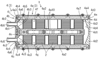
熱交換器1は、図2,3に示すようにハウジング3とハウジング3内に設けられる複数のペルチェモジュール(熱部材)2を有する。ハウジング3は、厚み方向に重ねられた第一ケース4と第二ケース5とコンバータケース6を有する。
The
第一ケース4は、図3,5に示すように樹脂製でかつ成形型によって成形されるケース本体4aを有する。ケース本体4aは、天部4a1と、天部4a1の両側縁から垂下する側壁4a2と、天部4a1の前縁から垂下する第一端面4a3と、天部4a1の後縁から垂下する第二端面4a4を一体に有する。天部4a1には、前縁と後縁に渡って延出して第一ケース4内を仕切る一対の仕切板4a10が形成される。仕切板4a10によって第一ケース4内には並行する複数の流路4f,4gが形成される。
As shown in FIGS. 3 and 5, the
第二ケース5は、図3,6に示すように樹脂製でかつ成形型によって成形されるケース本体5aを有する。ケース本体5aは、底部5a1と、底部5a1の両側縁に立設する側壁5a2と、底部5a1の前縁に立設する第一端面5a3と、底部5a1の後縁に立設する第二端面5a4を一体に有する。底部5a1には、前縁と後縁に渡って延出して第二ケース5内を仕切る一対の仕切板5a10が形成される。仕切板5a10によって第二ケース5内には並行する複数の流路5f,5gが形成される。
As shown in FIGS. 3 and 6, the
図3,5,6に示すようにケース本体4a,5aは、仕切板4a10,5a10と側壁4a2,5a2の間を延出する梁4a8,5a8を有する。梁4a8,5a8は、流路4f,4g,5f,5gを遮断しないように天部4a1または底部5a1から離れている。ケース本体4a,5aは、梁4a8,5a8と仕切板4a10,5a10と側壁4a2,5a2によって複数(例えば10個)の収納領域に区画される。ケース本体4aの各収納領域に各ペルチェモジュール2の上側部分が収容され、ケース本体5aの各収納領域に各ペルチェモジュール2の下側部分が収容される。
As shown in FIGS. 3, 5, and 6, the case
図3,5,6に示すように第一端面4a3,5a3には、流路4f,4g,5f,5gに開口する開口部4a6,5a6が形成される。第一端面4a3,5a3には、導入部材4b,5bと吐出部材4c,5cが取付けられる。第二端面4a4,5a4には、流路4f,4g,5f,5gに開口する開口部4a7,5a7が形成される。第二端面4a4,5a4には、折返し部材4d,5dが取付けられる。
As shown in FIGS. 3, 5 and 6,
図3,5,6に示すように導入部材4b,5bと吐出部材4c,5cは、樹脂製でかつ成形型によって成形される。導入部材4b,5bと吐出部材4c,5cは、第一端面4a3,5a3に取付けられる板状の取付部4b1,4c1,5b1,5c1を有し、取付部4b1,5b1と取付部4c1,5c1が一体に成形される。
As shown in FIGS. 3, 5, and 6, the
図3,5,6に示すように導入部材4b,5bは、取付部4b1,5b1から突出する導入管4b2,5b2を有する。導入管4b2,5b2と取付部4b1,5b1には、第一の流路4f,5fと連通する導入路4b6,5b6が形成される。吐出部材4c,5cは、取付部4c1,5c1から突出する吐出管4c2,5c2を有する。吐出管4c2,5c2と取付部4c1,5c1には、第二の流路4f,5fと連通する吐出路4c6,5c6が形成される。
As shown in FIGS. 3, 5, and 6, the
図3,5,6に示すように取付部4b1,4c1,5b1,5c1には、ケース4,5に向けて突出する突出部4b3,4c3,5b3,5c3が形成される。突出部4b3,4c3,5b3,5c3は、略三角形状であって、外側面4b4,4c4,5b4,5c4と傾斜面4b5,4c5,5b5,5c5を有する。突出部4b3,4c3,5b3,5c3は、開口部4a6,5a6に嵌合されて、外側面4b4,4c4,5b4,5c4が開口部4a6,5a6の内周面に当接する。傾斜面4b5,5b5は、導入路4b6,5b6から遠くなるほど流路断面が大きくなるように導入路4b6,5b6に対して傾斜する。傾斜面4c5,5c5は、吐出路4c6,5c6に近づくほど流路断面が小さくなるように吐出路4c6,5c6に対して傾斜する。
As shown in FIGS. 3, 5, and 6, the mounting
図5,6に示すように各取付部4b1,4c1,5b1,5c1には、開口部4a6,5a6に沿って凹部が形成される。凹部には、取付部4b1,4c1,5b1,5c1と第一端面4a3,5a3を液密にするシール部材4j,4k,5j,5kが収納される。取付部4b1,4c1,5b1,5c1は、第一端面4a3,5a3の外側面に対してねじ等の取付具によって取付けられる。
As shown in FIGS. 5 and 6, recesses are formed in the
図3,5,6に示すように折返し部材4d,5dは、樹脂製でかつ成形型によって成形される。折返し部材4d,5dは、第二端面4a4,5a4に取付けられる取付部4d1,5d1と、取付部4d1,5d1から突出する一対の突出部4d2,5d2を有する。突出部4d2,5d2は、略三角形状であって、外側面4d3,5d3と傾斜面4d4,5d4を有する。
As shown in FIGS. 3, 5, and 6, the
図3,5,6に示すように突出部4d2,5d2は、開口部4a7,5a7に嵌合されて、外側面4d3,5d3が開口部4a7,5a7の内周面に当接する。傾斜面4d4,5d4は、対向する流路4f,4g,5f,5gに対して他の流路4f,4g,5f,5gに向けて傾斜する。これにより第一流路4f,5fから第二流路4g,5gに熱媒体が円滑に折返して流れ得る。取付部4d1,5d1には、開口部4a7,5a7に沿って凹部が形成される。凹部には、取付部4d1,5d1と第二端面4a4,5a4を液密にするシール部材4m,5mが収納される。取付部4d1,5d1は、第二端面4a4,5a4の外側面にねじ等の取付具によって取付けられる。
As shown in FIGS. 3, 5 and 6, the
図3,4に示すようにケース本体4a,5aは、側壁4a2,5a2から外方に突出する複数の円筒部4a5,5a5を有する。円筒部4a5,5a5内には金属管4e,5eが設けられる。金属管4e,5eは、真鍮等の金属から形成されてケース本体4a,5aの成形時にインサートされる。金属管4e,5eは、円筒部4a5,5a5を高さ方向に貫通する。第一金属管4eは、円筒部4a5から第二金属管5eに突出する突出端部4e1を有する。第二金属管5eは、円筒部5a5から第一金属管4eに突出する突出端部5e1を有する。第二金属管5eは、第一金属管4eの内径よりも小さい内径を有する。第二金属管5eの内周面には雌ねじが形成される。
As shown in FIGS. 3 and 4, the case
図4に示すようにケース本体4a,5aには、対向する面に収納凹部4a12,5a12と小凹部4a11,5a11が形成される。収納凹部4a12,5a12には、ペルチェモジュール2の中央部(ペルチェ素子2aと基板2b,2c)が収容される。収納凹部4a12,5a12の深さは、ペルチェモジュール2の中央部の厚みよりも大きい。小凹部4a11,5a11は、収納凹部4a12,5a12の外周に沿って形成され、小凹部4a11,5a11に弾性部材8,9が設置される。
As shown in FIG. 4, in the case
図7に示すように弾性部材8,9は、ゴム製であって、板状でかつ環状である。弾性部材8,9の板幅8a,9aは、板厚8b,9bよりも大きい。弾性部材8,9は、板幅8a,9aが高さ方向になり、長手方向が環状になるように形成される。弾性部材8,9は、小凹部4a11,5a11(図4参照)と同様に四角形環状に形成される。板幅8a,9aは、小凹部4a11,5a11の深さよりも高く(図4参照)、弾性変形された状態でペルチェモジュール2の基板2b,2cに当接する。弾性部材8,9の弾性変形量は、例えば1mm程度である。弾性部材8,9は、基板2b,2cとケース本体4a,5aの間を液密にする。
As shown in FIG. 7, the
図4に示すようにケース本体4aには、ペルチェモジュール2の外側において環状に凹部が形成される。凹部にはケース本体4a,5a間を液密にするシール部材18が設けられる。図3に示すようにケース本体4aの天部4a1の中央には、一対の開口部4hが形成される。開口部4hは、コンバータケース6によって覆われる。
As shown in FIG. 4, an annular recess is formed in the
図3に示すようにコンバータケース6は、アルミニウム製であって底部6aと底部6aの外周縁に立設する外周壁6bを一体に有する。外周壁6bには外方に突出する複数のリング状のリング部6cが形成される。リング部6cは、第一金属管4eの端部に当接される。図4に示すようにケース本体4aには、開口部4hの外側において環状に凹部が形成される。凹部にはケース本体4aとコンバータケース6を液密にするシール部材17が設置される。
As shown in FIG. 3,
図2,4に示すようにケース4,5とコンバータケース6は、厚み方向に重ねられ、結合具7によって接合される。結合具(ボルト)7は、頭部7aと、頭部7aよりも細くかつ外周面に雄ねじが形成されたねじ本体7bを一体に有する。ねじ本体7bは、リング部6cの孔6c1と第一金属管4eを貫通し、第二金属管5eに螺合される。頭部7aは、リング部6cの端部に当接する。あるいはねじ本体7bは、第一金属管4eを貫通し、第二金属管5eに螺合される。頭部7aは、第一金属管4eの端部に当接する。
As shown in FIGS. 2 and 4, the
図4に示すようにペルチェモジュール(熱部材)2は、ペルチェ素子2aと基板2b,2cとフィン2d,2eを有する。ペルチェ素子2aは、異なる金属、導体または半導体から構成される。ペルチェ素子2aは、直流電流を流すことでペルチェ効果を奏し、第一熱面と第二熱面のいずれか一つが吸熱部となって吸熱し、他の一つが放熱部となって放熱する。複数のペルチェ素子2aが第一基板2bと第二基板2cの間に設けられる。ペルチェ素子2aの第一熱面が第一基板2bに当接されかつ半田付けされ、第二熱面が第二基板2cに当接されかつ半田付けされる。
As shown in FIG. 4, the Peltier module (thermal member) 2 includes a
図4に示すようにフィン2d,2eは、基板2b,2cからペルチェ素子2aと反対方向に突出する。フィン2d,2eは、板状でかつジグザグ形状であって、ジグザグ間に隙間2d1,2e1が形成される。隙間2d1,2e1は、流路4f,4g,5f,5gを遮断しないように流路4f,4g,5f,5gの長手方向に広がっている。
As shown in FIG. 4, the
図2に示すようにコンバータケース6には、コンバータ16が装着される。コンバータ16は、電気的にケース本体4aから延出する端子4nと接続される。コンバータ16は、コンバータ16に入力された電圧を所定の電圧に変換し、直流電流を端子4nに供給する。直流電流は、端子4nからケース本体4a内を延出する図示省略の配線を介して各ペルチェモジュール2の各ペルチェ素子2aに供給される(図4参照)。ペルチェ素子2aは、電流が供給されることで、第一フィン2dと第一基板2bを介して吸熱し、第二基板2cと第二フィン2eを介して放熱する。
As shown in FIG. 2, a
図1に示すように第一熱媒体がポンプ13によって配管20,21を経由して第一ケース4に供給される。第一熱媒体は、図2,3に示すように導入路4b6から第一流路4fに導入され、第二流路4gを経て吐出路4c6から排出される。第一熱媒体は、流路4f,4gを流れることで第一フィン2dと第一基板2bを介してペルチェ素子2aから冷熱を受ける(図4参照)。
As shown in FIG. 1, the first heat medium is supplied to the
図1に示すように第二熱媒体がポンプ15によって配管22を経由して第二ケース5に供給される。第二熱媒体は、図2,3に示すように導入路5b6から第一流路5fに導入され、第二流路5gを経て吐出路5c6から排出される。第二熱媒体は、流路5f,5gを流れることで第二フィン2eと第二基板2cを経由してペルチェ素子2aから温熱を受ける(図4参照)。第二熱媒体は、図1に示すように室内熱交換器14を流れて室内の空気に温熱を放出する。
As shown in FIG. 1, the second heat medium is supplied to the
図3に示すように第一ケース4内の第一熱媒体の流れ方向と第二ケース5内の第二熱媒体の流れ方向は、対向している。そのためペルチェモジュール2の吸熱部側と放熱部側の差は、ペルチェモジュール2間で差が小さい。かくして全体の熱効率が高い。
As shown in FIG. 3, the flow direction of the first heat medium in the
図2,3に示すように第一熱媒体は、ケース本体4aの開口部4hを介してコンバータケース6に接触する。第一熱媒体は、コンバータ16から発せられた熱をコンバータケース6を経由して受ける。したがって第一熱媒体は、コンバータ16を冷却する。
As shown in FIGS. 2 and 3, the first heat medium contacts the
以上のように熱交換器1は、図3,5,6に示すように並行する複数の流路4f,4g,5f,5gが形成され、複数の流路4f,4g,5f,5gの一端が開口する開口部4a6,5a6が形成される第一端面4a3,5a3と複数の流路4f,4g,5f,5gの他端が開口する開口部4a7,5a7が形成される第二端面4a4,5a4を有するハウジング3と、一つの開口部4a6,5a6の位置にて第一端面4a3,5a3に固定され、導入路4b6,5b6が形成された導入部材4b,5bと、第二端面4a4,5a4に形成される一対の開口部4a7,5a7に跨るように第二端面4a4,5a4に固定され、一対の開口部4a7,5a7を折返して接続する折返し部材4d,5dと、一つの開口部4a6,5a6の位置にて第一端面4a3,5a3に固定され、吐出路4c6,5c6が形成された吐出部材4c,5cとを有する。複数の流路4f,4g,5f,5gは折返し部材4d,5dにより一本の流路に接続される。一本の流路の最上流側の開口部4a6,5a6に導入部材4b,5bが設けられ、一本の流路の最下流側の開口部4a6,5a6に吐出部材4c,5cが設けられる。導入部材4b,5bと折返し部材4d,5dと吐出部材4c,5cは、ハウジング3に取付けられる取付部4b1,4c1,4d1,5b1,5c1,5d1と、取付部4b1,4c1,4d1,5b1,5c1,5d1よりもハウジング3側に突出し、流れ方向に対して傾斜している傾斜面4b5,4c5,4d4,5b5,5c5,5d4を有する突出部4b3,4c3,4d2,5b3,5c3,5d2を一体に有する。
As described above, the
したがって突出部4b3,4c3,4d2,5b3,5c3,5d2の傾斜面4b5,4c5,4d4,5b5,5c5,5d4によって熱媒体が円滑に流路4f,4g,5f,5gに導入、折返しあるいは吐出され得る。また突出部4b3,4c3,4d2,5b3,5c3,5d2は、ハウジング3に取付けられる取付部4b1,4c1,4d1,5b1,5c1,5d1に一体に設けられる。そのためハウジング3内に突出部4b3,4c3,4d2,5b3,5c3,5d2を一体に設ける場合に比べて簡易に突出部4b3,4c3,4d2,5b3,5c3,5d2が形成され得る。
Therefore, the heat medium is smoothly introduced into the
図5,6に示すようにハウジング3の開口部4a6,4a7,5a6,5a7に突出部4b3,4c3,4d2,5b3,5c3,5d2が嵌合される。したがって開口部4a6,4a7,5a6,5a7の構成壁面と突出部4b3,4c3,4d2,5b3,5c3,5d2の隙間が小さく、あるいは無くなる。そのため開口部4a6,4a7,5a6,5a7の構成壁面と突出部4b3,4c3,4d2,5b3,5c3,5d2の間から熱媒体が漏れることが抑制され得る。また突出部4b3,4c3,4d2,5b3,5c3,5d2のハウジング3に対する位置合わせも容易に行える。
As shown in FIGS. 5 and 6, the
図5,6に示すように取付部4b1,4c1,4d1,5b1,5c1,5d1とハウジング3の間にシール部材4j,4k,4m,5j,5k,5mが設けられる。したがってハウジング3内の熱媒体は、シール部材4j,4k,4m,5j,5k,5mによって取付部4b1,4c1,4d1,5b1,5c1,5d1とハウジング3の間からハウジング3の外へ漏れることが規制され得る。またシール部材4j,4k,4m,5j,5k,5mは、取付部4b1,4c1,4d1,5b1,5c1,5d1とハウジング3の間に設けられるために、突出部4b3,4c3,4d2,5b3,5c3,5d2をハウジング3に挿入する際の邪魔になり難い。
As shown in FIGS. 5 and 6,
図5,6に示すように導入部材4b,5bが突出部4b3,5b3を有し、該突出部4b3,5b3が導入路4b6,5b6から遠くなるほど流路断面を大きくする傾斜面4b5,5b5を有する。吐出部材4c,5cが突出部4c3,5c3を有し、該突出部4c3,5c3が吐出路4c6,5c6へ近づくほど流路断面を小さくする傾斜面4c5,5c5を有する。したがって熱媒体が導入路4b6,5b6から流路4f,5fへ導入する際の圧力損失が小さくなり、流路4g,5gから吐出路4c6,5c6へ吐出す際の圧力損失が小さくなる。かくして熱媒体をより円滑に流路4f,4g,5f,5gに導入しかつ吐出し得る。
As shown in FIGS. 5 and 6, the
図5,6に示すように取付部4b1,4c1,4d1,5b1,5c1,5d1と突出部4b3,4c3,4d2,5b3,5c3,5d2を備える部材4b,4c,4d,5b,5c,5dが樹脂製である。したがって該部材4b,4c,4d,5b,5c,5dは、金属製などに比べて容易に複雑な形状を有し得る。
As shown in FIGS. 5 and 6,
図3,4に示すように熱交換器1は、流路4f,4g内の熱媒体と熱交換を行う熱部材(ペルチェモジュール2)を有する。熱部材は、一対の熱面を備えかつ熱面の一つが吸熱し他の一つが放熱するペルチェ素子2aと、熱面の一つに当接される第一基板2bと、第一基板2bに設けられる第一フィン2dを有し、第一フィン2dが流路4f,4g内に位置する。したがってペルチェ素子2aの一つの熱面からの冷熱が第一基板2bを介して第一フィン2dによって熱媒体に伝えられる。
As shown in FIGS. 3 and 4, the
図4に示すように熱部材(ペルチェモジュール2)は、ペルチェ素子2aの熱面の他の一つに当接される第二基板2cと、第二基板2cに設けられる第二フィン2eを有する。ハウジング3は、第一フィン2dが内設される流路4f,4gが形成された第一ケース4と、第二フィン2eが内設される流路5f,5gが形成された第二ケース5を有する。したがってペルチェ素子2aの一つの熱面からの冷熱が第一フィン2dによって第一ケース4内の熱媒体に伝えられる。ペルチェ素子2aの他の熱面からの温熱が第二フィン2eによって第二ケース5内の熱媒体に伝えられる。
As shown in FIG. 4, the thermal member (Peltier module 2) has a second substrate 2c that is in contact with the other thermal surface of the
本発明は、上記実施の形態に限定されず、以下の形態であっても良い。例えば熱交換システム10は、車両の室内の暖房に使用されても良いし、冷房に使用されても良い。冷房に使用する場合は、第一ケース4が配管22と接続され、第二ケース5が配管21と接続される。
The present invention is not limited to the above-described embodiment, and may be the following form. For example, the
熱交換システム10は、車両の室内の冷暖房に使用されても良いし、電池等の車両部品の冷却または加熱に使用されても良いし、あるいは車両以外の製品を冷却または加熱するために使用されても良い。
The
ケース本体4a,5aは、樹脂製でも良いし、アルミダイカスト製でも良い。
The
熱媒体の流れを変える邪魔板が導入部材4b,5bに一体に、あるいは吐出部材4c,5cに一体に、あるいは折返し部材4d,5dに一体に設けられても良い。
A baffle plate that changes the flow of the heat medium may be provided integrally with the
ペルチェモジュール2とケース本体4a,5aの間には、弾性部材8,9が設けられても良いし、設けられていなくても良い。あるいは弾性部材8,9の一つのみが設けられていても良い。あるいは基板2b,2cがケース本体4a,5aに液状ガスケットによって弾性的に保持されても良い。あるいはケース本体4a,5aには、小凹部4a11,5a11が設けられておらず、ケース本体4a,5aと基板2b,2cの間に弾性部材が設けられても良い。
Between the
ケース4,5内に供給される熱媒体は、液体でも良いし、気体でも良い。
The heat medium supplied into the
ケース4,5は、樹脂製のケース本体4a,5aと金属製の金属管4e,5eを有していても良いし、金属製のケース本体4a,5aと金属管4e,5eを一体にあるいは別体に有していても良い。
The
ハウジング3には、ペルチェモジュール(熱部材)2の吸熱部側と熱交換を行うための流路4f,4gと、放熱部側と熱交換を行うための流路5f,5gが形成されても良いし、吸熱部側の流路4f,4gのみが形成され、放熱部側が大気と熱交換あるいは他のハウジングに放熱部側の流路が形成されていても良い。またはハウジング3には、放熱部側の流路5f,5gのみが形成され、吸熱部側が大気と熱交換あるいは他のハウジングに吸熱部側の流路が形成されていても良い。
Even if the
導入部材4b,5bと吐出部材4c,5cは、ハウジング3の第一端面4a3,5a3に取付けられも良いし、第二端面4a4,5a4に取付けられても良い。折返し部材4d,5dは、ハウジング3の第二端面4a4,5a4に取付けられても良いし、第一端面4a3,5a3に取付けられも良い。導入部材4b,5bと吐出部材4c,5cは、ハウジング3の同一端面に取付けられても良いし、別の端面に取付けられても良い。折返し部材4d,5dは、導入部材4b,5bまたは吐出部材4c,5cが取付けられるハウジング3の端面と異なる端面に取付けられても良いし、同じ端面に取付けられても良い。
The
ハウジング3には、並行する二つ流路4f,4g;5f,5gが形成されても良いし、並行する三つ以上の流路が形成されかつ該流路に対応する導入部材4b,5bと吐出部材4c,5cと折返し部材4d,5dが取付けられても良い。
Two
突出部4b3,4c3,4d2,5b3,5c3,5d2の傾斜面4b5,4c5,4d4,5cb5,5c5,5d4は、平面でも良いが、曲面であっても良い。 The inclined surfaces 4b5, 4c5, 4d4, 5cb5, 5c5, and 5d4 of the protrusions 4b3, 4c3, 4d2, 5b3, 5c3, and 5d2 may be flat surfaces or curved surfaces.
熱部材は、ペルチェモジュール2であっても良いし、熱を発して熱媒体に温熱を供給する他の部材、あるいは熱を吸収して熱媒体に冷熱を供給する他の部材であっても良い。
The heat member may be the
取付部4b1,4c1,4d1,5b1,5c1,5d1は、板状であっても良いし、他の形状であっても良い。 The attachment portions 4b1, 4c1, 4d1, 5b1, 5c1, and 5d1 may be plate-shaped or other shapes.
熱部材2は、流路4f,4g,5f,5g内に張出すフィン2d,2eを有していても良いし、ハウジング3に隣接しかつ流路4f,4g,5f,5g内の熱媒体と接する部材を有していても良いし、あるいはハウジング3に隣接しハウジング3の壁面を介して流路4f,4g,5f,5g内の熱媒体と熱交換しても良い。
The
1…熱交換器
2…ペルチェモジュール(熱部材)
2a…ペルチェ素子
2b,2c…基板
2d,2e…フィン
3…ハウジング
4,5…ケース
4a,5a…ケース本体
4a6,4a7,5a6,5a7,4h…開口部
4a10,5a10…仕切板
4a11,5a11…小凹部
4a12,5a12…収納凹部
4b,5b…導入部材
4b1,4c1,4d1,5b1,5c1,5d1…取付部
4b3,4c3,4d2,5b3,5c3,5d2…突出部
4b5,4c5,4d4,5b5,5c5,5d4…傾斜面
4b6,5b6…導入路
4c,5c…吐出部材
4c6,5c6…吐出路
4d,5d…折返し部材
4e,5e…金属管
4e1,5e1…突出端部
4f,4g,5f,5g…流路
4j,4k,4m,5j,5k,5m…シール部材
6…コンバータケース
7…結合具
8,9…弾性部材
8a,9a…板幅
8b,9b…板厚
10…熱交換システム
11…ラジエタ
12…エンジン
13,15…ポンプ
14…室内熱交換器
17,18…シール部材
1 ...
2a ...
図3,5,6に示すように突出部4d2,5d2は、開口部4a7,5a7に嵌合されて、外側面4d3,5d3が開口部4a7,5a7の内周面に当接する。傾斜面4d4,5d4は、対向する流路4f,4g,5f,5gに対して他の流路4f,4g,5f,5gに向けて傾斜する。すなわち傾斜面4d4は、外側面4d3から離れるに従い取付部4d1に近づくように傾斜し、傾斜面5d4は、外側面5d3から離れるに従い取付部5d1に近づくように傾斜する。これにより第一流路4f,5fから第二流路4g,5gに熱媒体が円滑に折返して流れ得る。取付部4d1,5d1には、開口部4a7,5a7に沿って凹部が形成される。凹部には、取付部4d1,5d1と第二端面4a4,5a4を液密にするシール部材4m,5mが収納される。取付部4d1,5d1は、第二端面4a4,5a4の外側面にねじ等の取付具によって取付けられる。
As shown in FIGS. 3, 5 and 6, the
図4に示すようにケース本体4a,5aには、対向する面に収納凹部4a12,5a12と小凹部4a11,5a11が形成される。収納凹部4a12,5a12には、ペルチェモジュール2の中央部(ペルチェ素子2aと基板2b,2c)が収容される。収納凹部4a12,5a12の深さは、ペルチェモジュール2の中央部の厚みよりも大きい。すなわちペルチェモジュール2の中央部の厚みは、ペルチェモジュール2がケース本体4a,5aに組み付けられた状態で収納凹部4a12の底面と収納凹部5a12の底面の距離よりも小さい。小凹部4a11,5a11は、収納凹部4a12,5a12の外周に沿って形成され、小凹部4a11,5a11に弾性部材8,9が設置される。
As shown in FIG. 4, in the case
図3に示すように第一ケース4内の第一熱媒体の流れ方向と第二ケース5内の第二熱媒体の流れ方向は、相反する方向である。そのためペルチェモジュール2の吸熱部側と放熱部側の差は、ペルチェモジュール2間で差が小さい。かくして全体の熱効率が高い。
The flow direction of the second heat medium in the first case the first heat medium in the flow direction and the
Claims (7)
並行する複数の流路が形成され、前記複数の流路の一端が開口する開口部が形成される第一端面と前記複数の流路の他端が開口する開口部が形成される第二端面を有するハウジングと、
一つの前記開口部の位置にて前記第一端面又は前記第二端面に固定され、導入路が形成された導入部材と、
前記第一端面に形成される一対の前記開口部に跨るように前記第一端面に固定又は前記第二端面に形成される一対の前記開口部に跨るように前記第二端面に固定され、前記一対の開口部を折返して接続する折返し部材と、
一つの前記開口部の位置にて前記第一端面又は前記第二端面に固定され、吐出路が形成された吐出部材とを有し、
前記複数の流路は少なくとも一つの前記折返し部材により一本の流路に接続され、
前記一本の流路の最上流側の前記開口部に前記導入部材が設けられ、
前記一本の流路の最下流側の前記開口部に前記吐出部材が設けられ、
前記導入部材と前記折返し部材と前記吐出部材の少なくとも一つの部材は、前記ハウジングに取付けられる取付部と、前記取付部よりも前記ハウジング側に突出し、流れ方向に対して傾斜している傾斜面を有する突出部を一体に有する熱交換器。 A heat exchanger,
A second end surface in which a plurality of parallel flow paths are formed, a first end surface in which an opening in which one end of the plurality of flow paths opens is formed, and an opening in which the other end of the plurality of flow paths is opened A housing having
An introduction member fixed to the first end surface or the second end surface at the position of the one opening and having an introduction path formed;
Fixed to the second end face so as to straddle the pair of openings formed on the second end face, or fixed to the first end face so as to straddle the pair of openings formed on the first end face, A folding member for folding and connecting the pair of openings;
A discharge member fixed to the first end surface or the second end surface at the position of the one opening and having a discharge path formed thereon;
The plurality of flow paths are connected to one flow path by at least one folding member,
The introduction member is provided in the opening on the most upstream side of the one flow path;
The discharge member is provided in the opening on the most downstream side of the one flow path,
At least one member of the introduction member, the folding member, and the discharge member includes an attachment portion that is attached to the housing, and an inclined surface that protrudes closer to the housing than the attachment portion and is inclined with respect to the flow direction. The heat exchanger which has the protrusion part which has integrally.
前記ハウジングの前記開口部に前記突出部が嵌合される熱交換器。 The heat exchanger according to claim 1,
A heat exchanger in which the protrusion is fitted into the opening of the housing.
前記取付部と前記ハウジングの間にシール部材が設けられる熱交換器。 The heat exchanger according to claim 1 or 2,
A heat exchanger in which a seal member is provided between the mounting portion and the housing.
前記導入部材が前記突出部を有し、該突出部が前記導入路から遠くなるほど流路断面を大きくする前記傾斜面を有し、
前記吐出部材が前記突出部を有し、該突出部が前記吐出路へ近づくほど流路断面を小さくする前記傾斜面を有する熱交換器。 The heat exchanger according to any one of claims 1 to 3,
The introduction member has the protrusion, and the protrusion has the inclined surface that enlarges the cross section of the flow path as the distance from the introduction path increases.
The heat exchanger having the inclined surface in which the discharge member has the protruding portion, and the flow passage cross section becomes smaller as the protruding portion approaches the discharge path.
前記取付部と前記突出部を備える前記導入部材と前記折返し部材と前記吐出部材が樹脂製である熱交換器。 It is a heat exchanger as described in any one of Claims 1-4, Comprising:
A heat exchanger in which the introduction member, the folding member, and the discharge member including the attachment portion and the protrusion are made of resin.
前記流路内の熱媒体と熱交換を行う熱部材を有し、
前記熱部材は、一対の熱面を備えかつ前記熱面の一つが吸熱し他の一つが放熱する熱面を備えるペルチェ素子と、前記熱面の一つに当接される第一基板と、前記第一基板に設けられる第一フィンを有し、前記第一フィンが前記流路内に位置する熱交換器。 It is a heat exchanger as described in any one of Claims 1-5,
A heat member that exchanges heat with the heat medium in the flow path;
The thermal member includes a pair of thermal surfaces, a Peltier element having a thermal surface in which one of the thermal surfaces absorbs heat and the other one dissipates, a first substrate in contact with one of the thermal surfaces, A heat exchanger having first fins provided on the first substrate, wherein the first fins are located in the flow path.
前記熱部材は、前記ペルチェ素子の前記熱面の他の一つに当接される第二基板と、前記第二基板に設けられる第二フィンを有し、
前記ハウジングは、前記第一フィンが内設される前記流路が形成された第一ケースと、前記第二フィンが内設される前記流路が形成された第二ケースを有する熱交換器。 The heat exchanger according to claim 6,
The thermal member has a second substrate that comes into contact with the other one of the thermal surfaces of the Peltier element, and a second fin provided on the second substrate,
The housing includes a first case in which the flow path in which the first fin is provided is formed, and a second case in which the flow path in which the second fin is provided is formed.
Priority Applications (5)
| Application Number | Priority Date | Filing Date | Title |
|---|---|---|---|
| JP2011060234A JP5229344B2 (en) | 2011-03-18 | 2011-03-18 | Heat exchanger |
| US13/416,224 US20120234021A1 (en) | 2011-03-18 | 2012-03-09 | Heat exchanger |
| KR1020120024943A KR101286875B1 (en) | 2011-03-18 | 2012-03-12 | Heat exchanger |
| EP12158999.8A EP2500682A3 (en) | 2011-03-18 | 2012-03-12 | Heat exchanger |
| CN2012100670682A CN102679794A (en) | 2011-03-18 | 2012-03-14 | Heat exchanger |
Applications Claiming Priority (1)
| Application Number | Priority Date | Filing Date | Title |
|---|---|---|---|
| JP2011060234A JP5229344B2 (en) | 2011-03-18 | 2011-03-18 | Heat exchanger |
Publications (2)
| Publication Number | Publication Date |
|---|---|
| JP2012193937A true JP2012193937A (en) | 2012-10-11 |
| JP5229344B2 JP5229344B2 (en) | 2013-07-03 |
Family
ID=45977166
Family Applications (1)
| Application Number | Title | Priority Date | Filing Date |
|---|---|---|---|
| JP2011060234A Expired - Fee Related JP5229344B2 (en) | 2011-03-18 | 2011-03-18 | Heat exchanger |
Country Status (5)
| Country | Link |
|---|---|
| US (1) | US20120234021A1 (en) |
| EP (1) | EP2500682A3 (en) |
| JP (1) | JP5229344B2 (en) |
| KR (1) | KR101286875B1 (en) |
| CN (1) | CN102679794A (en) |
Families Citing this family (8)
| Publication number | Priority date | Publication date | Assignee | Title |
|---|---|---|---|---|
| DE102013003414B4 (en) * | 2013-02-28 | 2019-10-31 | Webasto SE | Heat exchanger |
| KR101820424B1 (en) * | 2014-05-13 | 2018-01-19 | 엘지이노텍 주식회사 | Device using thermoelectric moudule |
| US10112271B2 (en) * | 2015-03-26 | 2018-10-30 | Hamilton Sundstrand Corporation | Compact heat exchanger |
| JP6868633B2 (en) * | 2016-09-23 | 2021-05-12 | 住友精密工業株式会社 | Cooling system |
| EP3842726A1 (en) | 2019-12-25 | 2021-06-30 | Showa Denko Packaging Co., Ltd. | Heat exchanger and inner fin thereof |
| KR102343882B1 (en) * | 2020-03-30 | 2021-12-24 | 김성완 | Chiller System for Semiconductor Process |
| CN111917337B (en) * | 2020-06-29 | 2021-07-23 | 天津商业大学 | Thermoelectric power generation device utilizing thermochemical reaction |
| KR102546351B1 (en) * | 2021-03-31 | 2023-06-21 | 한양대학교 산학협력단 | Apparatus for controlling cooling water temprerature of cooling tower |
Citations (4)
| Publication number | Priority date | Publication date | Assignee | Title |
|---|---|---|---|---|
| JPS51139464U (en) * | 1975-05-02 | 1976-11-10 | ||
| JP2002372335A (en) * | 2001-06-12 | 2002-12-26 | Smc Corp | Heat exchanger, and heat exchange apparatus using it |
| JP2003148148A (en) * | 2001-11-08 | 2003-05-21 | Yanmar Co Ltd | Air cooler of internal combustion engine with supercharger |
| JP2008528944A (en) * | 2005-02-02 | 2008-07-31 | キャリア コーポレイション | Small channel heat exchanger with a header with reduced dimensions |
Family Cites Families (19)
| Publication number | Priority date | Publication date | Assignee | Title |
|---|---|---|---|---|
| US1868661A (en) * | 1931-12-10 | 1932-07-26 | Griscom Russell Co | Heat exchanger |
| NL113071C (en) * | 1961-06-12 | |||
| US4286528A (en) * | 1979-08-30 | 1981-09-01 | Stephen Willard | Exhaust filter system |
| US5450896A (en) * | 1994-01-25 | 1995-09-19 | Wynn's Climate Systems, Inc. | Two-piece header |
| JPH09280772A (en) | 1996-04-12 | 1997-10-31 | Ishikawajima Harima Heavy Ind Co Ltd | Manufacture of tubular cylindrical heat exchanger |
| EP0952017A3 (en) * | 1998-04-22 | 2002-01-23 | Climcon A/S | A heat exchanger device for an air conditioning system |
| JP2001004245A (en) | 1999-06-18 | 2001-01-12 | Daikin Ind Ltd | Thermoelectric converter |
| US20040068991A1 (en) * | 1999-10-07 | 2004-04-15 | Ben Banney | Heat exchanger for an electronic heat pump |
| JP3479477B2 (en) * | 1999-12-16 | 2003-12-15 | Smc株式会社 | Heat exchanger for temperature controller |
| US7007750B2 (en) * | 2001-02-28 | 2006-03-07 | Showa Denko K.K. | Heat exchanger |
| JP2004116913A (en) * | 2002-09-26 | 2004-04-15 | Toyo Radiator Co Ltd | Heat exchanger |
| DE10312788A1 (en) * | 2003-03-21 | 2004-09-30 | Behr Gmbh & Co. Kg | Exhaust gas heat exchanger and sealing device for exhaust gas heat exchanger |
| JP4293054B2 (en) * | 2003-09-26 | 2009-07-08 | 株式会社デンソー | Air conditioner for vehicles |
| DE202005012879U1 (en) * | 2005-08-12 | 2005-10-27 | CALORPLAST WÄRMETECHNIK GmbH | Tubular heat exchanger for corrosive media has a bundle of pipes with a two-part base consisting of an outer base part and an inner base plate screwed into the outer base part so that the inner base plate is connected to the bundle of pipes |
| US7448440B2 (en) * | 2005-12-14 | 2008-11-11 | Showa Denko K.K. | Heat exchanger |
| JP2007178053A (en) * | 2005-12-27 | 2007-07-12 | Calsonic Kansei Corp | Heat exchanger |
| DE102008011341A1 (en) * | 2008-02-27 | 2009-09-03 | Evonik Röhm Gmbh | Heat exchanger for heating temperature and residence time sensitive products |
| JP5176624B2 (en) * | 2008-03-18 | 2013-04-03 | ダイキン工業株式会社 | Refrigeration equipment |
| KR20100029572A (en) * | 2008-09-08 | 2010-03-17 | 한라공조주식회사 | A heat exchanger using thermoelectric element modules |
-
2011
- 2011-03-18 JP JP2011060234A patent/JP5229344B2/en not_active Expired - Fee Related
-
2012
- 2012-03-09 US US13/416,224 patent/US20120234021A1/en not_active Abandoned
- 2012-03-12 EP EP12158999.8A patent/EP2500682A3/en not_active Withdrawn
- 2012-03-12 KR KR1020120024943A patent/KR101286875B1/en not_active IP Right Cessation
- 2012-03-14 CN CN2012100670682A patent/CN102679794A/en active Pending
Patent Citations (4)
| Publication number | Priority date | Publication date | Assignee | Title |
|---|---|---|---|---|
| JPS51139464U (en) * | 1975-05-02 | 1976-11-10 | ||
| JP2002372335A (en) * | 2001-06-12 | 2002-12-26 | Smc Corp | Heat exchanger, and heat exchange apparatus using it |
| JP2003148148A (en) * | 2001-11-08 | 2003-05-21 | Yanmar Co Ltd | Air cooler of internal combustion engine with supercharger |
| JP2008528944A (en) * | 2005-02-02 | 2008-07-31 | キャリア コーポレイション | Small channel heat exchanger with a header with reduced dimensions |
Also Published As
| Publication number | Publication date |
|---|---|
| EP2500682A2 (en) | 2012-09-19 |
| CN102679794A (en) | 2012-09-19 |
| US20120234021A1 (en) | 2012-09-20 |
| JP5229344B2 (en) | 2013-07-03 |
| KR20120106575A (en) | 2012-09-26 |
| KR101286875B1 (en) | 2013-07-16 |
| EP2500682A3 (en) | 2015-01-21 |
Similar Documents
| Publication | Publication Date | Title |
|---|---|---|
| JP5229344B2 (en) | Heat exchanger | |
| JP5488510B2 (en) | Thermoelectric conversion unit | |
| JP4876975B2 (en) | Cooling device and heat receiving member for electronic equipment | |
| US8081460B2 (en) | Liquid-cooled heat radiator | |
| JPH08264692A (en) | Cooling device for electronic parts | |
| US20170213779A1 (en) | Semiconductor device | |
| JP2013008736A (en) | Thermoelectric conversion module and method for manufacturing thermoelectric conversion module | |
| JP2012209305A (en) | Thermoelectric conversion unit and manufacturing method of the same | |
| WO2003043397A1 (en) | Electronic apparatus | |
| TWI363408B (en) | ||
| JP2013008734A (en) | Thermoelectric conversion unit | |
| JP5117287B2 (en) | Electronic equipment cooling system | |
| TWM609021U (en) | Liquid cooling heat dissipation device and liquid cooling heat dissipation system with the same | |
| JP2011134978A (en) | Fluid cooling type heat sink | |
| JP2006332393A (en) | Water-cooled heatsink | |
| WO2022127746A1 (en) | Cabinet assembly and heat exchanger | |
| KR20120107867A (en) | Heat pump system | |
| JP2005011928A (en) | Liquid-cooling circulation system | |
| JP2013008737A (en) | Thermoelectric conversion unit | |
| JP2012204752A (en) | Thermoelectric conversion module, manufacturing method thereof, and thermoelectric conversion unit with thermoelectric conversion module | |
| JP2003197839A (en) | Boiler/cooler for heater element | |
| US20220203806A1 (en) | Cooling device and vehicle including the same | |
| WO2023276939A1 (en) | Thermal device heat sink | |
| US11178789B2 (en) | Combination air-water cooling device | |
| JP2005123260A (en) | Water-cooled heatsink |
Legal Events
| Date | Code | Title | Description |
|---|---|---|---|
| A621 | Written request for application examination |
Free format text: JAPANESE INTERMEDIATE CODE: A621 Effective date: 20120702 |
|
| A977 | Report on retrieval |
Free format text: JAPANESE INTERMEDIATE CODE: A971007 Effective date: 20130212 |
|
| TRDD | Decision of grant or rejection written | ||
| A01 | Written decision to grant a patent or to grant a registration (utility model) |
Free format text: JAPANESE INTERMEDIATE CODE: A01 Effective date: 20130219 |
|
| A61 | First payment of annual fees (during grant procedure) |
Free format text: JAPANESE INTERMEDIATE CODE: A61 Effective date: 20130304 |
|
| FPAY | Renewal fee payment (event date is renewal date of database) |
Free format text: PAYMENT UNTIL: 20160329 Year of fee payment: 3 |
|
| LAPS | Cancellation because of no payment of annual fees |