JP2012193701A - Particulate-matter processing device - Google Patents
Particulate-matter processing device Download PDFInfo
- Publication number
- JP2012193701A JP2012193701A JP2011059364A JP2011059364A JP2012193701A JP 2012193701 A JP2012193701 A JP 2012193701A JP 2011059364 A JP2011059364 A JP 2011059364A JP 2011059364 A JP2011059364 A JP 2011059364A JP 2012193701 A JP2012193701 A JP 2012193701A
- Authority
- JP
- Japan
- Prior art keywords
- exhaust
- exhaust gas
- particulate matter
- electrode
- internal combustion
- Prior art date
- Legal status (The legal status is an assumption and is not a legal conclusion. Google has not performed a legal analysis and makes no representation as to the accuracy of the status listed.)
- Withdrawn
Links
Images


Landscapes
- Exhaust Gas After Treatment (AREA)
- Processes For Solid Components From Exhaust (AREA)
Abstract
Description
本発明は、排気通路に電極を有し、その電極への電圧印加によって排気中の粒子状物質を凝集させる粒子状物質処理装置に関する。 The present invention relates to a particulate matter processing apparatus having an electrode in an exhaust passage and aggregating particulate matter in the exhaust by applying a voltage to the electrode.
内燃機関の排気通路に放電電極を設け、該放電電極からコロナ放電を発生させることにより粒子状物質(以下、PMともいう。)を帯電させてPMを凝集させる技術が知られている(例えば、特許文献1参照。)。PMを凝集させることにより、結果的には、単位体積当たりに含まれるPMの粒子数を減少させることができる。また、凝集の結果としてのPMは、その粒子径が大きくなるため、例えば、放電電極の下流側にフィルタを設けた場合には、該フィルタにてPMを捕集しやすくなる。 A technique is known in which a discharge electrode is provided in an exhaust passage of an internal combustion engine, and corona discharge is generated from the discharge electrode to charge particulate matter (hereinafter also referred to as PM) to agglomerate PM (for example, (See Patent Document 1). By aggregating PM, as a result, the number of PM particles contained per unit volume can be reduced. Moreover, since the particle diameter of PM as a result of aggregation increases, for example, when a filter is provided on the downstream side of the discharge electrode, it becomes easy to collect PM by the filter.
内燃機関の排気通路に電極を設け、該電極に電圧印加をすることで排気通路を流れる排気中のPMを帯電させて、PMを凝集させることで、排気に含まれる単位体積当たりのPM数を低減させることが可能となる。これは、PMの粒子数に起因する環境への負荷軽減に大きく寄与するものである。ここで、内燃機関から排出される排気の流量は、該内燃機関の機関負荷等に応じて変動するものであるが、排気流量が増加するとPMが有する慣性力が増加する等の理由により、上記のPM帯電凝集が良好に行われにくくなる。 An electrode is provided in the exhaust passage of the internal combustion engine, and by applying a voltage to the electrode, the PM in the exhaust gas flowing through the exhaust passage is charged and aggregated, thereby reducing the number of PM per unit volume contained in the exhaust gas. It can be reduced. This greatly contributes to reducing the environmental load caused by the number of PM particles. Here, the flow rate of the exhaust gas discharged from the internal combustion engine varies depending on the engine load of the internal combustion engine, etc., but the reason is that the inertial force of the PM increases as the exhaust flow rate increases. PM charge aggregation is difficult to be performed satisfactorily.
本発明は、上記問題に鑑みてなされたものであり、電極を用いて排気中のPMを帯電させることによるPM凝集を好適に行う粒子状物質処理装置を提供することを目的とする。 The present invention has been made in view of the above problems, and an object of the present invention is to provide a particulate matter processing apparatus that suitably performs PM aggregation by charging PM in exhaust using an electrode.
本発明においては、上記課題を解決するために、電極を用いて排気中のPMを帯電させることによるPM凝集を行うための処理部を、内燃機関につながる排気通路のうち、排気浄化装置の下流側に位置する排気通路に設けることとした。排気浄化装置の下流側に処理部を配置することで、流速が低減された排気を処理部に流れ込ませ、効率的なPM凝集を図ろうとするものである。 In the present invention, in order to solve the above-described problem, a processing unit for performing PM aggregation by charging PM in exhaust using an electrode is provided downstream of the exhaust purification device in the exhaust passage connected to the internal combustion engine. It was decided to be provided in the exhaust passage located on the side. By disposing the processing unit on the downstream side of the exhaust gas purification apparatus, exhaust with reduced flow velocity is caused to flow into the processing unit, and efficient PM aggregation is attempted.
詳細には、本発明は、排気中の粒子状物質を凝集させる粒子状物質処理装置であって、内燃機関の排気通路に設けられ、該内燃機関から排出される排気の浄化を行う排気浄化装置と、前記排気浄化装置の下流側に位置する排気通路において、印加電圧を変更可能な電極を有し、該電極への印加電圧により該電極と該排気通路との間の、該排気浄化装置から流れ出る排気が通る空間に電流を流す処理部と、を備える。 More specifically, the present invention relates to a particulate matter processing apparatus that agglomerates particulate matter in exhaust gas, and is provided in an exhaust passage of an internal combustion engine and purifies exhaust gas exhausted from the internal combustion engine. And an exhaust passage located on the downstream side of the exhaust purification device, and an electrode whose applied voltage can be changed, and the exhaust purification device between the electrode and the exhaust passage by the applied voltage to the electrode. And a processing section for passing an electric current through a space through which the exhaust gas flowing out passes.
本発明に係る粒子状物質処理装置においては、上記処理部が備えられることにより、排気通路で電極への電圧印加が制御されて、電極と排気通路との間の空間、すなわち排気が流れる空間(以下、「帯電空間」という。)に電流が流れ、以て排気中のPMが帯電されることになる。その結果、PM同士が静電気力によって凝集したり、また、帯電したPMが排気通路側へ誘引され、そこでPM同士が凝集したりする結果、排気中のPMの粒子径が大きくなるとともに、そこに含まれる単位体積当たりの粒子数を低減することが可能と
なる。
In the particulate matter processing apparatus according to the present invention, by providing the processing unit, voltage application to the electrode is controlled in the exhaust passage, and the space between the electrode and the exhaust passage, that is, the space in which exhaust flows ( Hereinafter, the current flows in the “charging space”), and the PM in the exhaust is charged. As a result, PM aggregates due to electrostatic force, or charged PM is attracted to the exhaust passage side, and as a result, the PMs aggregate together. As a result, the particle size of the PM in the exhaust gas increases, It is possible to reduce the number of particles per unit volume contained.
そして、上記粒子状物質処理装置においては、この処理部は、排気浄化のための排気浄化装置の下流側に設けられる。排気通路に設けられた排気浄化装置では、排気中に含まれたNOx等を浄化すべく排気と接触し、排気浄化に必要な物理的、化学的反応が生じる場でもある。そのため、排気浄化装置の具体的な態様に応じて幾ばくかの程度の差はあるものの、排気浄化装置は排気の流れに対する抵抗となり得、そのため、排気浄化装置を通過した排気については、通過する前と比べてその流速が低下されるため、そこに含まれるPMの慣性力を低減させることが可能となる。PM同士の凝集は、PM間に働く静電力(クーロン力)とPMが有する慣性力とのバランスの上で実現されるため、排気浄化装置の通過によりPMの慣性力が低減されると、相対的にPM間の静電力が強まることになり、以てPM同士の凝集が促進されることになる。 And in the said particulate matter processing apparatus, this process part is provided in the downstream of the exhaust gas purification apparatus for exhaust gas purification. In the exhaust gas purification device provided in the exhaust passage, it comes into contact with the exhaust gas to purify NOx and the like contained in the exhaust gas, and is a place where a physical and chemical reaction necessary for exhaust gas purification occurs. Therefore, although there is a slight difference depending on the specific mode of the exhaust purification device, the exhaust purification device can be a resistance to the flow of exhaust gas. Since the flow velocity is reduced as compared with the above, the inertial force of the PM contained therein can be reduced. Aggregation between PMs is realized on the balance between the electrostatic force (Coulomb force) acting between the PMs and the inertial force of the PMs. Therefore, if the PM inertial force is reduced by passing through the exhaust purification device, Therefore, the electrostatic force between the PMs is strengthened, and the aggregation of the PMs is promoted.
ここで、上記粒子状物質処理装置において、前記排気浄化装置は、前記内燃機関から排出される排気の浄化を行う複数の排気浄化触媒が直列に並んだ排気浄化触媒群を有し、その場合、前記処理部は、前記排気浄化触媒群のうち最下流側の排気浄化触媒よりも、更に下流側に設けられてもよい。排気通路に設けられた排気浄化装置として、排気浄化の目的に応じて複数の排気浄化触媒に順次排気が流れ込むように形成された排気浄化触媒群が採用される場合がある。たとえば、酸化触媒、NOx浄化用のNOx触媒、所定の排気浄化触媒が担持されたフィルタ等が直列に配置されて排気浄化装置が形成されてもよい。このように排気浄化触媒群によって排気浄化装置が形成される場合には、処理部を当該群のうち最後尾(最下流側)に位置する排気浄化触媒の更に下流側に配置することで、より効果的に流速を低減した排気を処理部に供給することができ、以て効率的なPM凝集が期待される。なお、処理部を、排気浄化触媒群を構成する2つの触媒の間に挟むように設けても構わない。 Here, in the particulate matter processing device, the exhaust purification device has an exhaust purification catalyst group in which a plurality of exhaust purification catalysts for purifying exhaust discharged from the internal combustion engine are arranged in series, The processing unit may be provided further on the downstream side than the exhaust purification catalyst on the most downstream side in the exhaust purification catalyst group. As an exhaust purification device provided in the exhaust passage, an exhaust purification catalyst group formed so that exhaust flows sequentially into a plurality of exhaust purification catalysts depending on the purpose of exhaust purification may be employed. For example, an exhaust purification device may be formed by arranging in series an oxidation catalyst, a NOx catalyst for NOx purification, a filter carrying a predetermined exhaust purification catalyst, and the like. In this way, when the exhaust purification device is formed by the exhaust purification catalyst group, by disposing the processing unit further downstream of the exhaust purification catalyst located at the rearmost (most downstream side) of the group, Exhaust gas with a reduced flow rate can be effectively supplied to the processing unit, so that efficient PM aggregation is expected. The processing unit may be provided so as to be sandwiched between two catalysts constituting the exhaust purification catalyst group.
また、上記粒子状物質処理装置において、前記排気浄化装置の下流側の前記排気通路には、そこを流れる排気の排気音を消音する消音装置が設けられ、前記処理部は、前記消音装置の一部として形成されてもよい。消音装置は、排気の圧力を低下させその流速を低減させる装置であることを踏まえて、処理部を消音装置の一部として形成することで、換言すれば、消音装置の内部に処理部を含めるように該消音装置を形成することで、処理部そのものには、流速低下された排気が供給されることになり、効率的なPM凝集が期待される。 Further, in the particulate matter treatment device, the exhaust passage downstream of the exhaust purification device is provided with a silencer that silences the exhaust sound of the exhaust gas flowing therethrough, and the processing unit is a part of the silencer. It may be formed as a part. In view of the fact that the silencer is a device that lowers the pressure of exhaust gas and reduces the flow velocity thereof, the processing unit is formed as a part of the silencer, in other words, the processing unit is included in the silencer. By forming the silencer as described above, exhaust gas having a reduced flow velocity is supplied to the processing unit itself, and efficient PM aggregation is expected.
また、上記粒子状物質処理装置において同じように消音装置が設けられる場合、前記処理部は、前記消音装置の下流側に設けられてもよい。すなわち、消音装置によって減圧、流速低下された排気が、その後処理部に供給されるように、該消音装置の下流側に該処理部を配置する構成が採用される。この構成により、より確実に流速低下された排気が供給されることになり、効率的なPM凝集が期待される。 Moreover, when a silencer is provided similarly in the particulate matter treatment apparatus, the processing unit may be provided on the downstream side of the silencer. That is, a configuration is adopted in which the processing unit is arranged on the downstream side of the silencer so that the exhaust gas whose pressure is reduced and the flow velocity is reduced by the silencer is supplied to the processing unit thereafter. With this configuration, exhaust gas with a reduced flow rate is more reliably supplied, and efficient PM aggregation is expected.
なお、上述までの場合、処理部が有する排気通路の形状や大きさに応じて、該処理部自体が消音機能を発揮することも可能である。すなわち、処理部内の空間は、電極からの電子放出によりPMを帯電させるための帯電空間でもあり、また、その空間による排気の流速低下が期待できる場合には消音のための消音空間ともなり得る。そこで、消音のための消音装置による除去周波数と処理部による除去周波数とが異なるように、それぞれの容量を設計することで、換言すれば、消音装置と処理部とが協働して排気消音を達成するように設計することで、消音装置の容量を小さくすることが可能である。たとえば、消音装置が低周波領域を除去し、処理部が高周波領域を除去するように設計すれば、消音装置自体が両周波領域を除去する場合と比べて、その装置全体の容量を小さくすることができる。 In the case described above, the processing unit itself can also exhibit a silencing function according to the shape and size of the exhaust passage of the processing unit. That is, the space in the processing section is also a charging space for charging the PM by emitting electrons from the electrodes, and can also be a silencing space for silencing if a decrease in the exhaust gas flow velocity can be expected due to the space. Therefore, by designing the respective capacities so that the removal frequency by the silencer for silencing and the removal frequency by the processing unit are different, in other words, the silencer and the processing unit cooperate to perform exhaust silencing. By designing to achieve, it is possible to reduce the capacity of the silencer. For example, if the silencer is designed to remove the low frequency region and the processing unit removes the high frequency region, the capacity of the entire device can be reduced compared to the case where the silencer itself removes both frequency regions. Can do.
本発明によれば、電極を用いて排気中のPMを帯電させることによるPM凝集を好適に行う粒子状物質処理装置を提供することが可能となる。 ADVANTAGE OF THE INVENTION According to this invention, it becomes possible to provide the particulate matter processing apparatus which performs PM aggregation suitably by charging PM in exhaust gas using an electrode.
以下、本発明に係る粒子状物質処理装置の具体的な実施態様について図面に基づいて説明する。 Hereinafter, specific embodiments of the particulate matter processing apparatus according to the present invention will be described with reference to the drawings.
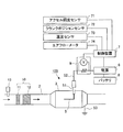
図1は、本発明の実施例に係る粒子状物質処理装置1の概略構成を示す図である。粒子状物質処理装置1は、例えばガソリン機関の排気通路2に設けられ、また、ディーゼル機関の排気通路に設けることもできる。いずれの内燃機関の排気通路に設けられる場合であれ、電極5への電圧印加により排気中のPMを帯電させ、PM同士の凝集を促進させることで、排気中のPM粒子の粒径増大、それに伴う粒子数の低減を図ることができる。以下に、粒子状物質処理装置1の詳細を説明する。
FIG. 1 is a diagram showing a schematic configuration of a particulate matter processing apparatus 1 according to an embodiment of the present invention. The particulate matter processing apparatus 1 is provided, for example, in an
粒子状物質処理装置1は、両端が排気通路2に接続されているハウジング3を備えて構成される。ハウジング3の材料には、ステンレス鋼材を用いている。ハウジング3は、排気通路2よりも直径の大きな中空の円柱形に形成されている。ハウジング3の両端は、端部に近くなるほど断面積が小さくなるテーパ状に形成されている。なお、図1においては、排気が排気通路2を矢印の方向に流れて、ハウジング3内に流入する。このため、ハウジング3は排気通路2の一部としてもよい。なお、本実施例においてはハウジング3の内部の空間が、上記の帯電空間となる。
The particulate matter processing apparatus 1 includes a
ここで、排気通路2とハウジング3とは、絶縁部4を介して接続されている。絶縁部4は、電気の絶縁体からなる。絶縁部4は、排気通路2の端部に形成されるフランジ21と、ハウジング3の端部に形成されるフランジ31と、に挟まれる。排気通路2とハウジング3とは、たとえばボルト及びナットにより締結される。そして、これらボルト及びナットを介して電気が流れないように、これらボルト及びナットにも絶縁処理を施しておく。このようにして、排気通路2とハウジング3との間には電気的絶縁状態が形成されている。
Here, the
ハウジング3には、電極5が取り付けられている。電極5は、ハウジング3の側面を貫通しており、該ハウジング3の側面から該ハウジング3の中心軸方向へ延びて該中心軸近傍において排気の流れの上流側へ折れ曲がり、該中心軸と平行に排気の流れの上流側へ向かって伸びている。このため、電極5の端部はハウジング3の中心軸近傍に位置する。また、電極5とハウジング3とが直接接触して電気が流れないように、電極5には電気的絶
縁体からなる碍子部51が設けられている。この碍子部51は、電極5とハウジング3との間に位置しており、電気を絶縁すると共に、電極5をハウジング3に固定するための機能を有する。このように碍子部51を介して電極5がハウジング3に取り付けられることで、該電極5がハウジング3内の帯電空間内に位置することになる。
An
そして、電極5は電源側電線52を介して電源6に接続されている。電源6は、電極5へ通電すると共に、印加電圧を変更することができる。この電源6は、電線を介して制御装置7及びバッテリ8に接続されている。制御装置7は、電源6が電極5に印加する電圧を制御する。
The
また、ハウジング3には接地側電線53が接続されており、該ハウジング3は接地側電線53を介して接地されている。接地側電線53には、該接地側電線53を通る電流を検出する検出装置9が設けられている。検出装置9は、例えば、接地側電線53の途中に設けられる抵抗の両端の電位差を測定することで電流を検出する。この検出装置9は、電線を介して制御装置7に接続されている。このような構成により、検出装置9により検出される電流が制御装置7に入力される。
A ground side
なお、制御装置7には、アクセル開度センサ71、クランクポジションセンサ72、温度センサ73、エアフローメータ74が接続されている。アクセル開度センサ71は、粒子状物質処理装置1が接続された内燃機関を搭載する車両の運転者がアクセルペダルを踏み込んだ量に応じた電気信号を出力し、その機関負荷を検出する。クランクポジションセンサ72は、当該内燃機関の機関回転数を検出する。温度センサ73は、当該内燃機関の冷却水の温度または潤滑油の温度を検出することで内燃機関の温度を検出する。エアフローメータ74は、当該内燃機関の吸入空気量を検出する。
Note that an
このように構成された粒子状物質処理装置1では、電源6から電極5へ負の直流高電圧を印加することで、該電極5から電子が放出され、電極5とハウジング3との間の帯電空間を通して電流が流れる。すなわち、ハウジング3よりも電極5のほうの電位を低くすることで、電極5から電子を放出させている。そして、この電子により排気中のPMを負に帯電させることができる。負に帯電したPMは、クーロン力とガス流によって移動する。そして、PMがハウジング3へ到達すると、PMを負に帯電させた電子は該ハウジング3を通り、設置側電線53を介して外部へと流れ出る。この結果、ハウジング3へ電子を放出したPM同士は、互いに凝集して粒子径が大きくなる。また、PMが凝集することで、排気中の単位体積当たりのPMの粒子数は低減する。このように、電極5へ電圧を印加することで、PMの粒子径を大きくし且つ排気中の単位体積当たりのPMの粒子数を低減させることができる。
In the particulate matter processing apparatus 1 configured as described above, by applying a negative DC high voltage from the
なお、本実施例では、電極5を排気の流れの上流側に向けて折り曲げているが、これに代えて、下流側に向けて折り曲げてもよい。ここで、本実施例のように、電極5を排気の流れの上流側に向けて折り曲げると、碍子部51にPMが付着し難い。すなわち、碍子部51よりも上流側においてPMを帯電されることができるため、該PMがハウジング3の内周面に向かう。このため、碍子部51に衝突するPMが減少するので、該碍子部51にPMが付着し難くなる。しかし、電極5を排気の流れの上流側へ向けて折り曲げると、排気の流れから力を受けて電極5が変形し易い。このため、電極5が短い場合に適している。一方、電極5を排気の流れの下流側に向けて折り曲げると、碍子部51にPMが付着し易いが、排気の流れから力を受けても電極5が変形し難い。このため、耐久性及び信頼性が高く、電極5を長くすることができる。
In the present embodiment, the
ここで、本発明に係る粒子状物質処理装置1については、排気中のNOx等を浄化するための排気浄化装置10が排気通路2に設けられ、その下流側に粒子状物質処理装置1が
配置されている。具体的には、排気の流れに沿ったときのハウジング3の上流側の端部が接続される排気通路2に、排気浄化装置10が設置され、排気浄化装置10を通った排気が下流側のハウジング3内に流れ込むように構成されている。そして、排気浄化装置10は、排気浄化を行うために既知の様々な一又は複数の排気浄化触媒で形成することが可能である。例えば、排気中のNOxを除去するために、排気の流れにおいて上流側に酸化触媒11、下流側にNOx吸蔵還元型触媒(NOx触媒)12を直列に配置して排気浄化装置10を形成してもよい。この場合、酸化触媒11の上流側には、還元剤である燃料を添加する添加弁13が配置される。また、別の具体例としては、排気の流れに沿って上流側から加水分解触媒、NOx選択還元型触媒、酸化触媒を順次並べて形成される構成を、排気浄化装置10に適用してもよい。この場合、加水分解触媒の上流側には、還元剤である尿素を添加する添加弁が配置される。これらの具体的形態におけるNOx吸蔵還元型触媒12やNOx選択還元型触媒については、内燃機関を搭載する車両の床下に配置される形態から床下触媒とも称される。各具体的形態における排気浄化のための制御については既知であるため、本明細書での詳細な説明は割愛する。
Here, with respect to the particulate matter treatment apparatus 1 according to the present invention, an
このように粒子状物質処理装置1を排気浄化装置10の下流側に配置することで、内燃機関から排出された排気は、先ず排気浄化装置10を通った後に粒子状物質処理装置1のハウジング3内へ流れ込む。排気浄化装置10を形成する酸化触媒11およびNOx触媒12は、一般には、担体部材に触媒金属等が担持された構成となっており、排気が触媒内に流れ込むことでこの触媒金属と接触し、排気浄化に必要な所定の反応が生じることになる。そのため、排気浄化装置10を形成する各触媒は、排気に対して抵抗となり得、ハウジング3内に流れ込む排気の流速は、排気浄化装置10内に流れ込む際の排気流速よりも低下する。その結果、排気に含まれるPMが有する慣性力が低減される。電極5への電圧印加によって生じるPM同士の凝集は、PM間に働く静電力(クーロン力)とPMが有する慣性力とのバランスの上で実現されるため、排気浄化装置10の存在によってPMの慣性力が低減されると、相対的にPM間の静電力が強まることになり、以てPM同士の凝集が促進されることになる。この結果、PM粒子数の低減処理をより効率的に実施できるため、排気中のPM処理に要する電力を抑制することも可能となる。
By disposing the particulate matter treatment device 1 on the downstream side of the
ここで、冷却された排気中のPM粒子数の低減処理について、図2に基づいて説明する。図2は、本実施例に係るPM粒子数の低減処理のための印加電圧の制御フローを示したフローチャートである。本ルーチンは、内燃機関の稼働に併せて、制御装置7により所定の時間毎に繰り返し実行される。この制御装置7は、実質的にはCPU、メモリ、ハードディスク等を含むコンピュータに相当し、そこで制御プログラムが実行されることで図2に示すフローチャートに係る処理やその他の処理等が実行される。
Here, the process of reducing the number of PM particles in the cooled exhaust gas will be described with reference to FIG. FIG. 2 is a flowchart showing a control flow of the applied voltage for the process of reducing the number of PM particles according to the present embodiment. This routine is repeatedly executed every predetermined time by the
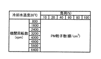
まず、S101からS103の処理において、排気中に含まれるPM粒子数(個/cm3)が算出される。PM粒子数は、一立方センチメートルあたりのPM粒子の数である。このPM粒子数は、内燃機関から排出されるPM粒子数であり、ハウジング3に流入する前のPM粒子数である。PM粒子数は、機関回転数、機関負荷、及び内燃機関の温度(たとえば、潤滑油の温度または冷却水の温度)と相関関係にあるため、これらの値に基づいて算出する。
First, in the processing from S101 to S103, the number of PM particles (number / cm 3 ) contained in the exhaust gas is calculated. The number of PM particles is the number of PM particles per cubic centimeter. The number of PM particles is the number of PM particles discharged from the internal combustion engine, and is the number of PM particles before flowing into the
このため、S101では、機関回転数及び機関負荷が取得される。機関回転数は、クランクポジションセンサ72により検出され、機関負荷は、アクセル開度センサ71により検出される。また、S102では、内燃機関の温度が取得される。内燃機関の温度は温度センサ73により検出される。
For this reason, in S101, the engine speed and the engine load are acquired. The engine speed is detected by a
S103では、PM粒子数が算出される。ここで、図3は、機関回転数と機関負荷とから、PM粒子数を算出するためのマップの一例を示した図である。この関係は、内燃機関
の温度に応じて制御装置7が複数記憶している(図3に示すのは、内燃機関の温度が20℃の場合のマップである。)。そして、S102で検出された内燃機関の温度に応じたマップを用いて機関回転数及び機関負荷からPM粒子数が求められる。このマップは、予め実験等により準備されている。なお、このようなマップを用いてPM粒子数を検出してもよいが、PM粒子数を検出するセンサをハウジング3よりも上流側の排気通路2に取り付けて、該センサによりPM粒子数を直接検出してもよい。
In S103, the number of PM particles is calculated. Here, FIG. 3 is a diagram showing an example of a map for calculating the number of PM particles from the engine speed and the engine load. A plurality of this relationship is stored in the
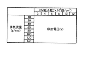
次に、S104では、S103で算出されるPM粒子数に基づいて電極5への印加電圧が算出される。この印加電圧は、内燃機関が始動し排気通路2内を排気が流れ始めたときに電極5へ最初に印加する電圧である。そして、S104で算出される印加電圧を初期値として、過電流が発生しない範囲で印加電圧が最も大きくなるようにフィードバック制御を行う(S105の処理)。具体的には、検出装置9によって検出される電流値が所定の閾値を超えないように、電極5への印加電圧がフィードバック制御される。ここで、印加電圧の初期値は図4に示すマップに基づいて設定される。
Next, in S104, the applied voltage to the
図4は、内燃機関からの排気流量(g/sec)とPM粒子数(×105個/cm3)とから、印加電圧(V)を算出するためのマップの一例を示した図である。このマップは、予め実験等により準備される。内燃機関からの排気流量は、内燃機関の吸入空気量と相関関係にあるため、エアフローメータ74により検出される吸入空気量に基づいて求めることができる。
FIG. 4 is a diagram showing an example of a map for calculating the applied voltage (V) from the exhaust flow rate (g / sec) from the internal combustion engine and the number of PM particles (× 10 5 particles / cm 3 ). . This map is prepared in advance by experiments or the like. Since the exhaust gas flow rate from the internal combustion engine has a correlation with the intake air amount of the internal combustion engine, it can be obtained based on the intake air amount detected by the
ここで、排気通路2を流れる排気流量が少ないほど、PMの慣性力が小さくなるため、相対的に静電作用の影響が大きくなる。このため、PM同士が凝集しやすくなる。したがって、排気流量が少ないほど、より小さな印加電圧でPM同士が凝集する。この点を踏まえて、図4に示すマップでは、排気流量が少ないほど印加電圧が小さくされている。一方で、PM粒子数が多いほど、PM粒子間の距離が短くなるために、相対的に静電作用の影響が大きくなる。このためPM粒子数が多いほど、より小さな印加電圧でPMが凝集する。この点を踏まえて、図4に示すマップでは、PM粒子数が多いほど印加電圧は小さくされている。なお、印加電圧の初期値としては、たとえば、PM粒子数の低減率が所定値(たとえば40%)となるような電圧値としてもよく、また、印加電圧の初期値を予め定めておいた規定値としてもよい。この規定値は、過電流が発生しないように余裕を持たせた値とすることができる。
Here, the smaller the exhaust flow rate flowing through the
このように、図2に示すように電極5への印加電圧をフィードバック制御することで、過電流が発生しない範囲で印加電圧を可及的に高くすることができる。これにより、PMの凝集をより促進させることができるため、PM粒子数をより減少させることができる。また、上記のとおり、排気浄化装置10の下流側に粒子状物質処理装置1を配置するため、そのハウジング3内に流れ込む排気の流速を低減させることができることから、PM粒子数の低減処理はより効率的に実現されることになる。
In this way, by applying feedback control to the applied voltage to the
なお、上述までの実施例においては、排気浄化装置10は複数の排気浄化触媒による触媒群で形成されていたが、単独の排気浄化触媒から形成される排気浄化装置10を採用しても構わない。
In the above-described embodiments, the
図5に、本発明に係る粒子状物質処理装置の第二の実施例に関する概略構成を示す。図5に示す粒子状物質処理装置100と図1に示す粒子状物質処理装置1と異なる点について説明する。図5に示す粒子状物質処理装置100では、電源6と、電極5と、の間の電源側電線52に、該電源側電線52を通る電流を検出する検出装置9が設けられている。このように、検出装置9を電源側電線52に設けることにより、図1に示される絶縁部4
は必要ない。すなわち、ハウジング3から排気通路2側へ電気が流れたとしても、検出装置9によれば電極5を通る電流を検出することができる。しかし、一般に、電源側電線52のほうが接地側電線53よりも、径が太く且つ長さが長くなるため、電気的な容量が大きくなる。したがって、図5に示す粒子状物質処理装置100については、コロナ放電などの強い放電が発生したとしても、図1に示す粒子状物質処理装置1と比べてパルス電流を検出し難くなる。
FIG. 5 shows a schematic configuration relating to the second embodiment of the particulate matter processing apparatus according to the present invention. Differences between the particulate
Is not necessary. That is, even if electricity flows from the
そこで、たとえば、図2に示す印加電圧のフィードバック制御を行う際に、パルス電流等の高周波成分を有する電流を検出し、それをフィードバック制御に反映させる必要がある場合には、図1に示す粒子状物質処理装置1が有用であり、そのような必要がない場合には、図5に示す形態の粒子状物質処理装置100も採用し得る。
Therefore, for example, when the feedback control of the applied voltage shown in FIG. 2 is performed, if it is necessary to detect a current having a high frequency component such as a pulse current and reflect it in the feedback control, the particles shown in FIG. When the particulate matter treatment apparatus 1 is useful and there is no need for such, the particulate
図6に、本発明に係る粒子状物質処理装置の第三の実施例に関する概略構成を示す。図6に示す粒子状物質処理装置110と図1に示す粒子状物質処理装置1と異なる点について説明する。図6に示す粒子状物質処理装置110は、排気浄化装置10の下流側に設けられた排気消音装置(いわゆるマフラー)13の更に下流側に設けられている。排気消音装置13は、図示しないが排気圧力を徐々に低減する構成となっており、その圧力低下に伴って排気の流速も低下する。そのため、図6に示すように排気消音装置13の下流側で粒子状物質処理装置110のハウジング3を接続することで、排気の流速を十分に低下させた後に、当該排気を、粒子状物質処理装置110によるPM粒子数の低減処理に供させることになる。その結果、当該低減処理が効率的に実現されることになる。
FIG. 6 shows a schematic configuration relating to the third embodiment of the particulate matter processing apparatus according to the present invention. Differences between the particulate
ここで、粒子状物質処理装置110のハウジング3の帯電空間は、排気通路2の断面積よりも大きな断面積を有し、またハウジング3自体が排気の流れに沿って所定の長さを有することから、ハウジング3内の帯電空間は、排気消音装置13と同じように、排気の圧力を低下させることで消音効果を発揮することが期待される。そこで、ハウジング3の大きさ、形状を、排気中のPM凝集の観点に加えて、排気消音の観点からも決定してもよい。具体的には、排気消音装置13による除去周波数を除去すべき排気音の周波数帯のうち低周波領域に設定した場合、残りの高周波領域の周波数についてはハウジング3によって除去できるように、そのハウジング3の大きさ、形状が決定される。これにより、排気消音装置13で達成すべき周波数領域が狭まるため、該装置13の容量を小さくすることができる。
Here, the charging space of the
また、図6に示す態様に代えて、粒子状物質処理装置110自体を排気消音装置13の内部に含まれるように構成してもよい。粒子状物質処理装置110が排気消音装置13の内部に存在することで、幾ばくかは当該装置13によって圧力低下され流速が低下した排気が粒子状物質処理装置110側に供給されることになるので、排気中のPM粒子数の低減処理が効率的に行われることになる。なお、このとき粒子状物質処理装置110のハウジング3として、排気消音装置13のハウジングを兼用して用いてもよい。すなわち、排気消音装置13のハウジングは、消音のための空間を画定するものでもあり、一部に帯電空間を画定するものでもある。
Further, instead of the embodiment shown in FIG. 6, the particulate
1・・・・粒子状物質処理装置
2・・・・排気通路
3・・・・ハウジング
4・・・・絶縁部
5・・・・電極
6・・・・電源
7・・・・制御装置
8・・・・バッテリ
9・・・・検出装置
10・・・・排気浄化装置
11・・・・酸化触媒
12・・・・NOx吸蔵還元型触媒
100・・・・粒子状物質処理装置
110・・・・粒子状物質処理装置
DESCRIPTION OF SYMBOLS 1 .... Particulate
Claims (4)
内燃機関の排気通路に設けられ、該内燃機関から排出される排気の浄化を行う排気浄化装置と、
前記排気浄化装置の下流側に位置する排気通路において、印加電圧を変更可能な電極を有し、該電極への印加電圧により該電極と該排気通路との間の、該排気浄化装置から流れ出る排気が通る空間に電流を流す処理部と、
を備える粒子状物質処理装置。 A particulate matter processing apparatus for aggregating particulate matter in exhaust gas,
An exhaust purification device that is provided in an exhaust passage of the internal combustion engine and purifies exhaust exhausted from the internal combustion engine;
Exhaust gas flowing out of the exhaust gas purification device between the electrode and the exhaust gas passage by an applied voltage to the electrode in an exhaust gas passage located downstream of the exhaust gas purification device. A processing section for passing an electric current through a space through which
A particulate matter processing apparatus comprising:
前記処理部は、前記排気浄化触媒群のうち最下流側の排気浄化触媒よりも、更に下流側に設けられる、
請求項1に記載の粒子状物質処理装置。 The exhaust purification device has an exhaust purification catalyst group in which a plurality of exhaust purification catalysts for purifying exhaust discharged from the internal combustion engine are arranged in series,
The processing section is provided further downstream than the exhaust purification catalyst on the most downstream side in the exhaust purification catalyst group,
The particulate matter processing apparatus according to claim 1.
前記処理部は、前記消音装置の一部として形成される、
請求項1又は請求項2に記載の粒子状物質処理装置。 The exhaust passage on the downstream side of the exhaust purification device is provided with a silencer that silences the exhaust sound of the exhaust flowing therethrough,
The processing unit is formed as a part of the silencer.
The particulate matter processing apparatus according to claim 1 or 2.
前記処理部は、前記消音装置の下流側に設けられる、
請求項1又は請求項2に記載の粒子状物質処理装置。 The exhaust passage on the downstream side of the exhaust purification device is provided with a silencer that silences the exhaust sound of the exhaust flowing therethrough,
The processing unit is provided on the downstream side of the silencer,
The particulate matter processing apparatus according to claim 1 or 2.
Priority Applications (1)
| Application Number | Priority Date | Filing Date | Title |
|---|---|---|---|
| JP2011059364A JP2012193701A (en) | 2011-03-17 | 2011-03-17 | Particulate-matter processing device |
Applications Claiming Priority (1)
| Application Number | Priority Date | Filing Date | Title |
|---|---|---|---|
| JP2011059364A JP2012193701A (en) | 2011-03-17 | 2011-03-17 | Particulate-matter processing device |
Publications (1)
| Publication Number | Publication Date |
|---|---|
| JP2012193701A true JP2012193701A (en) | 2012-10-11 |
Family
ID=47085810
Family Applications (1)
| Application Number | Title | Priority Date | Filing Date |
|---|---|---|---|
| JP2011059364A Withdrawn JP2012193701A (en) | 2011-03-17 | 2011-03-17 | Particulate-matter processing device |
Country Status (1)
| Country | Link |
|---|---|
| JP (1) | JP2012193701A (en) |
Cited By (2)
| Publication number | Priority date | Publication date | Assignee | Title |
|---|---|---|---|---|
| KR101408298B1 (en) | 2013-05-31 | 2014-07-11 | 운해이엔씨(주) | A removal apparatus of stench induce material and bio-aerosol |
| CN111852615A (en) * | 2020-07-21 | 2020-10-30 | 扬州大学 | Small-sized diesel engine carbon particle removing device in extremely cold environment and working method thereof |
-
2011
- 2011-03-17 JP JP2011059364A patent/JP2012193701A/en not_active Withdrawn
Cited By (2)
| Publication number | Priority date | Publication date | Assignee | Title |
|---|---|---|---|---|
| KR101408298B1 (en) | 2013-05-31 | 2014-07-11 | 운해이엔씨(주) | A removal apparatus of stench induce material and bio-aerosol |
| CN111852615A (en) * | 2020-07-21 | 2020-10-30 | 扬州大学 | Small-sized diesel engine carbon particle removing device in extremely cold environment and working method thereof |
Similar Documents
| Publication | Publication Date | Title |
|---|---|---|
| US9097155B2 (en) | Device for treating exhaust gas containing soot particles and motor vehicle having the device | |
| WO2013179381A1 (en) | Particulate matter treating device | |
| JP5333675B2 (en) | Particulate matter treatment equipment | |
| US8863496B2 (en) | Particulate matter control system and its failure determination method | |
| JP5590216B2 (en) | Particulate matter treatment equipment | |
| JP6447486B2 (en) | Discharge control device, gas supply device, and discharge control method | |
| JP5605499B2 (en) | Particulate matter treatment equipment | |
| JP2012193701A (en) | Particulate-matter processing device | |
| JP5691760B2 (en) | Particulate matter treatment equipment | |
| JP5605498B2 (en) | Particulate matter treatment equipment | |
| JP2006105081A (en) | Exhaust emission control device | |
| WO2012124088A1 (en) | Particulate-matter processing device | |
| JP2012193699A (en) | Particulate-matter processing device | |
| JP2012219746A (en) | Internal combustion engine system | |
| JP5531978B2 (en) | Exhaust treatment device for internal combustion engine | |
| JP2012193704A (en) | Particulate-matter processing device | |
| JP5655652B2 (en) | Particulate matter treatment equipment | |
| JP2005048753A (en) | Exhaust emission control device | |
| JP5590217B2 (en) | Particulate matter treatment equipment | |
| JP2012219733A (en) | Particulate-matter processing device | |
| JP2012193696A (en) | Particulate-matter processing device | |
| JP2012219677A (en) | Particulate-matter processing device | |
| JP2012092700A (en) | Device and method for detecting filter failure | |
| JP2012219669A (en) | Particulate-matter processing device | |
| JP5760548B2 (en) | Particulate matter treatment equipment |
Legal Events
| Date | Code | Title | Description |
|---|---|---|---|
| A300 | Withdrawal of application because of no request for examination |
Free format text: JAPANESE INTERMEDIATE CODE: A300 Effective date: 20140603 |