JP6447486B2 - Discharge control device, gas supply device, and discharge control method - Google Patents
Discharge control device, gas supply device, and discharge control method Download PDFInfo
- Publication number
- JP6447486B2 JP6447486B2 JP2015250293A JP2015250293A JP6447486B2 JP 6447486 B2 JP6447486 B2 JP 6447486B2 JP 2015250293 A JP2015250293 A JP 2015250293A JP 2015250293 A JP2015250293 A JP 2015250293A JP 6447486 B2 JP6447486 B2 JP 6447486B2
- Authority
- JP
- Japan
- Prior art keywords
- voltage
- gas
- electrode
- temperature
- search
- Prior art date
- Legal status (The legal status is an assumption and is not a legal conclusion. Google has not performed a legal analysis and makes no representation as to the accuracy of the status listed.)
- Expired - Fee Related
Links
Images


Classifications
-
- F—MECHANICAL ENGINEERING; LIGHTING; HEATING; WEAPONS; BLASTING
- F01—MACHINES OR ENGINES IN GENERAL; ENGINE PLANTS IN GENERAL; STEAM ENGINES
- F01N—GAS-FLOW SILENCERS OR EXHAUST APPARATUS FOR MACHINES OR ENGINES IN GENERAL; GAS-FLOW SILENCERS OR EXHAUST APPARATUS FOR INTERNAL COMBUSTION ENGINES
- F01N3/00—Exhaust or silencing apparatus having means for purifying, rendering innocuous, or otherwise treating exhaust
- F01N3/02—Exhaust or silencing apparatus having means for purifying, rendering innocuous, or otherwise treating exhaust for cooling, or for removing solid constituents of, exhaust
- F01N3/021—Exhaust or silencing apparatus having means for purifying, rendering innocuous, or otherwise treating exhaust for cooling, or for removing solid constituents of, exhaust by means of filters
-
- B—PERFORMING OPERATIONS; TRANSPORTING
- B01—PHYSICAL OR CHEMICAL PROCESSES OR APPARATUS IN GENERAL
- B01D—SEPARATION
- B01D53/00—Separation of gases or vapours; Recovering vapours of volatile solvents from gases; Chemical or biological purification of waste gases, e.g. engine exhaust gases, smoke, fumes, flue gases, aerosols
- B01D53/34—Chemical or biological purification of waste gases
- B01D53/92—Chemical or biological purification of waste gases of engine exhaust gases
- B01D53/94—Chemical or biological purification of waste gases of engine exhaust gases by catalytic processes
- B01D53/9404—Removing only nitrogen compounds
- B01D53/9409—Nitrogen oxides
-
- B—PERFORMING OPERATIONS; TRANSPORTING
- B01—PHYSICAL OR CHEMICAL PROCESSES OR APPARATUS IN GENERAL
- B01D—SEPARATION
- B01D53/00—Separation of gases or vapours; Recovering vapours of volatile solvents from gases; Chemical or biological purification of waste gases, e.g. engine exhaust gases, smoke, fumes, flue gases, aerosols
- B01D53/34—Chemical or biological purification of waste gases
- B01D53/92—Chemical or biological purification of waste gases of engine exhaust gases
- B01D53/94—Chemical or biological purification of waste gases of engine exhaust gases by catalytic processes
- B01D53/9495—Controlling the catalytic process
-
- C—CHEMISTRY; METALLURGY
- C01—INORGANIC CHEMISTRY
- C01B—NON-METALLIC ELEMENTS; COMPOUNDS THEREOF; METALLOIDS OR COMPOUNDS THEREOF NOT COVERED BY SUBCLASS C01C
- C01B13/00—Oxygen; Ozone; Oxides or hydroxides in general
- C01B13/10—Preparation of ozone
- C01B13/11—Preparation of ozone by electric discharge
-
- F—MECHANICAL ENGINEERING; LIGHTING; HEATING; WEAPONS; BLASTING
- F01—MACHINES OR ENGINES IN GENERAL; ENGINE PLANTS IN GENERAL; STEAM ENGINES
- F01N—GAS-FLOW SILENCERS OR EXHAUST APPARATUS FOR MACHINES OR ENGINES IN GENERAL; GAS-FLOW SILENCERS OR EXHAUST APPARATUS FOR INTERNAL COMBUSTION ENGINES
- F01N3/00—Exhaust or silencing apparatus having means for purifying, rendering innocuous, or otherwise treating exhaust
- F01N3/08—Exhaust or silencing apparatus having means for purifying, rendering innocuous, or otherwise treating exhaust for rendering innocuous
- F01N3/0807—Exhaust or silencing apparatus having means for purifying, rendering innocuous, or otherwise treating exhaust for rendering innocuous by using absorbents or adsorbents
-
- B—PERFORMING OPERATIONS; TRANSPORTING
- B01—PHYSICAL OR CHEMICAL PROCESSES OR APPARATUS IN GENERAL
- B01D—SEPARATION
- B01D2251/00—Reactants
- B01D2251/10—Oxidants
- B01D2251/104—Ozone
-
- C—CHEMISTRY; METALLURGY
- C01—INORGANIC CHEMISTRY
- C01B—NON-METALLIC ELEMENTS; COMPOUNDS THEREOF; METALLOIDS OR COMPOUNDS THEREOF NOT COVERED BY SUBCLASS C01C
- C01B2201/00—Preparation of ozone by electrical discharge
- C01B2201/90—Control of the process
-
- F—MECHANICAL ENGINEERING; LIGHTING; HEATING; WEAPONS; BLASTING
- F01—MACHINES OR ENGINES IN GENERAL; ENGINE PLANTS IN GENERAL; STEAM ENGINES
- F01N—GAS-FLOW SILENCERS OR EXHAUST APPARATUS FOR MACHINES OR ENGINES IN GENERAL; GAS-FLOW SILENCERS OR EXHAUST APPARATUS FOR INTERNAL COMBUSTION ENGINES
- F01N2240/00—Combination or association of two or more different exhaust treating devices, or of at least one such device with an auxiliary device, not covered by indexing codes F01N2230/00 or F01N2250/00, one of the devices being
- F01N2240/20—Combination or association of two or more different exhaust treating devices, or of at least one such device with an auxiliary device, not covered by indexing codes F01N2230/00 or F01N2250/00, one of the devices being a flow director or deflector
-
- F—MECHANICAL ENGINEERING; LIGHTING; HEATING; WEAPONS; BLASTING
- F01—MACHINES OR ENGINES IN GENERAL; ENGINE PLANTS IN GENERAL; STEAM ENGINES
- F01N—GAS-FLOW SILENCERS OR EXHAUST APPARATUS FOR MACHINES OR ENGINES IN GENERAL; GAS-FLOW SILENCERS OR EXHAUST APPARATUS FOR INTERNAL COMBUSTION ENGINES
- F01N2240/00—Combination or association of two or more different exhaust treating devices, or of at least one such device with an auxiliary device, not covered by indexing codes F01N2230/00 or F01N2250/00, one of the devices being
- F01N2240/38—Combination or association of two or more different exhaust treating devices, or of at least one such device with an auxiliary device, not covered by indexing codes F01N2230/00 or F01N2250/00, one of the devices being an ozone (O3) generator, e.g. for adding ozone after generation of ozone from air
-
- Y—GENERAL TAGGING OF NEW TECHNOLOGICAL DEVELOPMENTS; GENERAL TAGGING OF CROSS-SECTIONAL TECHNOLOGIES SPANNING OVER SEVERAL SECTIONS OF THE IPC; TECHNICAL SUBJECTS COVERED BY FORMER USPC CROSS-REFERENCE ART COLLECTIONS [XRACs] AND DIGESTS
- Y02—TECHNOLOGIES OR APPLICATIONS FOR MITIGATION OR ADAPTATION AGAINST CLIMATE CHANGE
- Y02T—CLIMATE CHANGE MITIGATION TECHNOLOGIES RELATED TO TRANSPORTATION
- Y02T10/00—Road transport of goods or passengers
- Y02T10/10—Internal combustion engine [ICE] based vehicles
- Y02T10/12—Improving ICE efficiencies
Landscapes
- Engineering & Computer Science (AREA)
- Chemical & Material Sciences (AREA)
- Combustion & Propulsion (AREA)
- Analytical Chemistry (AREA)
- Oil, Petroleum & Natural Gas (AREA)
- Health & Medical Sciences (AREA)
- Biomedical Technology (AREA)
- Environmental & Geological Engineering (AREA)
- Mechanical Engineering (AREA)
- General Chemical & Material Sciences (AREA)
- General Engineering & Computer Science (AREA)
- Chemical Kinetics & Catalysis (AREA)
- Organic Chemistry (AREA)
- Inorganic Chemistry (AREA)
- Oxygen, Ozone, And Oxides In General (AREA)
- Exhaust Gas After Treatment (AREA)
- Physical Or Chemical Processes And Apparatus (AREA)
Description
本発明は、放電制御装置、ガス供給装置及び放電制御方法に関する。 The present invention relates to a discharge control device, a gas supply device, and a discharge control method.
従来より、電極からの放電によりガスを改質するガス改質装置が知られている。例えば特許文献1では、内燃機関からの排気が通る排気通路に供給管が接続されており、電極からの放電によりオゾンを生成するオゾン生成部がガス改質装置として供給管に設けられている。この構成では、電圧の印加に伴って電極に流れる電流が電流検出回路により検出され、電極からの放電が発生したか否かの判定が電流の検出値に基づいて行われる。
2. Description of the Related Art Conventionally, gas reforming apparatuses that reform gas by discharging from an electrode are known. For example, in
しかしながら、例えばノイズ等により電流の検出精度が低下した場合、電極からの放電が発生したか否かの判定精度も低下しやすくなってしまう。特に、電極に電圧を印加するための電源回路内に電流検出回路が設けられた構成では、電源回路にて発生したノイズが電流検出回路の検出値に含まれやすく、電極からの放電が発生したか否かを判定することが困難になってしまう。この場合、電極への印加電圧が小さ過ぎて放電が生じないことや、印加電圧が大き過ぎて放電に際しても電力効率が低下することが懸念される。 However, when the current detection accuracy decreases due to noise or the like, for example, the determination accuracy as to whether or not the discharge from the electrode has occurred tends to decrease. In particular, in the configuration in which the current detection circuit is provided in the power supply circuit for applying a voltage to the electrode, noise generated in the power supply circuit is easily included in the detection value of the current detection circuit, and discharge from the electrode has occurred. It becomes difficult to determine whether or not. In this case, there is a concern that the applied voltage to the electrode is too small and no discharge occurs, or that the applied voltage is too large and the power efficiency is reduced during the discharge.
本発明は、上記問題を鑑みてなされたもので、その目的は、ガスの改質を確実に行いつつ、電力効率の向上を図った放電制御装置、ガス供給装置及び放電制御方法を提供することにある。 The present invention has been made in view of the above problems, and an object thereof is to provide a discharge control device, a gas supply device, and a discharge control method that improve power efficiency while reliably reforming a gas. It is in.
以下、課題を達成するための発明の技術的手段について、説明する。なお、発明の技術的手段を開示する特許請求の範囲及び本欄に記載された括弧内の符号は、後に詳述する実施形態に記載された具体的手段との対応関係を示すものであり、発明の技術的範囲を限定するものではない。 The technical means of the invention for achieving the object will be described below. The reference numerals in parentheses described in the scope of claims and this column disclosing technical means of the invention indicate the correspondence with the specific means described in the embodiment described in detail later. It is not intended to limit the technical scope of the invention.
上述の課題を解決するために開示された第1の発明は、
内燃機関(10)の排気が流れる排気通路(16)に接続されたガス通路(31)に設けられ、電極(41)からの放電によりガスの改質を行うガス改質装置(32)、の動作制御を行う放電制御装置(60)であって、
ガス通路においてガス改質装置の上流側及び下流側のそれぞれに設けられガスの温度を検出する温度センサ(37a,37b)の検出結果を用いて、ガス改質装置から流れ出るガスの温度をガス温度(T)として取得する温度取得部(S204,S209,S301,S305)と、
温度取得部の取得結果を用いてガス温度の上昇量(ΔT)を取得する上昇量取得部(S210,S306)と、
電極からの放電が生じる電圧を探索するべく、電極に印加される探索電圧(Vs)を可変設定する電圧設定部(74)と、
電圧設定部により探索電圧が増加するように設定された場合に、探索電圧の所定の増加量(Vadd)に対するガス温度の上昇量があらかじめ定められた判定値(A)より大きいか否かを判定する温度判定部(S211,S307)と、
ガス温度の上昇量が判定値より大きくなった場合の探索電圧を、ガス改質装置において放電が開始される放電開始電圧(Vdis)として取得する電圧取得部(S215)と、
を備えている。
In order to solve the above-mentioned problem, the first invention disclosed is
A gas reformer (32) provided in a gas passage (31) connected to an exhaust passage (16) through which exhaust gas from the internal combustion engine (10) flows , and reforming the gas by discharge from the electrode (41) ; A discharge control device (60) for controlling operation,
Using the detection results of temperature sensors (37a, 37b) provided on the upstream side and the downstream side of the gas reformer in the gas passage to detect the temperature of the gas, the temperature of the gas flowing out from the gas reformer is determined as the gas temperature. A temperature acquisition unit (S204, S209, S301, S305) acquired as (T);
An increase amount acquisition unit (S210, S306) that acquires an increase amount (ΔT) of the gas temperature using an acquisition result of the temperature acquisition unit;
A voltage setting unit (74) for variably setting a search voltage (Vs) applied to the electrode in order to search for a voltage at which discharge from the electrode occurs;
When the search voltage is set to increase by the voltage setting unit, it is determined whether or not the increase amount of the gas temperature with respect to the predetermined increase amount (Vadd) of the search voltage is larger than a predetermined determination value (A). A temperature determination unit (S211, S307),
A voltage acquisition unit (S215) for acquiring a search voltage when the gas temperature increase amount is larger than a determination value as a discharge start voltage (Vdis) at which discharge is started in the gas reformer;
It has.
発明者らは、電極からの放電が発生する場合、電界の中で電子雪崩が発生することで電極周辺のガスの温度が上昇しやすい、という知見を得た。この知見によれば、電極からの放電が発生している場合と発生していない場合とで、ガス改質装置から流れ出るガス温度の上昇量が異なる。 The inventors have obtained the knowledge that when an electric discharge occurs from an electrode, an electron avalanche occurs in an electric field, so that the temperature of the gas around the electrode tends to increase. According to this knowledge, the amount of increase in the gas temperature flowing out from the gas reformer differs depending on whether or not the discharge from the electrode is occurring.
これに対して、第1の発明によれば、電極に印加される探索電圧の増加に伴って、ガス温度の上昇量が判定値より大きいか否かの判定が行われるため、ガス温度の上昇量が判定値より大きくなった電圧を放電の開始を示す放電開始電圧として取得することができる。この場合、例えば電極周辺のガス圧力やガス改質装置の個体差、経年劣化等により放電の発生しやすさが異なっていたとしても、放電開始電圧を精度良く探索することができる。このため、排気の後処理等を目的としてガス改質装置によりガスの改質を行う場合に、電極に放電開始電圧を印加したにもかかわらずガスの改質が行われないということや、電極への電圧印加に伴う電力消費量が過剰に大きいということを回避できる。したがって、ガスの改質を確実に行いつつ、電力効率の向上を図ることができる。
開示された1つの発明は、
電極(41)からの放電によりガスの改質を行うガス改質装置(32)の動作制御を行う放電制御装置(60)であって、
ガス改質装置から流れ出るガスの温度をガス温度(T)として取得する温度取得部(S204,S209,S301,S305)と、
電極からの放電が生じる電圧を探索するべく、電極に印加される探索電圧(Vs)を可変設定する電圧設定部であって、電極への電圧の印加を開始する場合に、探索電圧をあらかじめ定められた初期電圧(Vbase)に設定する電圧設定部(74)と、
電圧設定部により探索電圧が増加するように設定された場合に、探索電圧の所定の増加量(Vadd)に対するガス温度の上昇量(ΔT)があらかじめ定められた判定値(A)より大きいか否かを判定する温度判定部(S211,S307)と、
ガス温度の上昇量が判定値より大きいと温度判定部により判定された場合に、電極への初期電圧の印加を停止する初期停止部(S216)と、
を備え、
電圧設定部は、初期停止部により初期電圧の印加が停止された後に、電極への電圧の印加を再開する場合に、初期電圧を所定値だけ小さい電圧に更新し、
温度判定部は、電極への電圧の印加が初期電圧にて開始された場合に、ガス温度の上昇量が判定値より大きいか否かを判定するものである。
On the other hand, according to the first invention, as the search voltage applied to the electrode increases, it is determined whether or not the increase amount of the gas temperature is larger than the determination value. A voltage whose amount is larger than the determination value can be acquired as a discharge start voltage indicating the start of discharge. In this case, the discharge start voltage can be searched with high precision even if the discharge pressure varies depending on, for example, the gas pressure around the electrode, the individual difference of the gas reformer, or the aging deterioration. For this reason, when gas reforming is performed by a gas reforming device for the purpose of after-treatment of exhaust gas, the fact that gas reforming is not performed despite the application of a discharge start voltage to the electrode, It can be avoided that the power consumption accompanying the voltage application to is excessively large. Therefore, it is possible to improve the power efficiency while reliably reforming the gas.
One disclosed invention is:
A discharge control device (60) for controlling the operation of a gas reforming device (32) for reforming a gas by discharging from an electrode (41),
A temperature acquisition unit (S204, S209, S301, S305) for acquiring the temperature of the gas flowing out from the gas reformer as the gas temperature (T);
A voltage setting unit that variably sets a search voltage (Vs) applied to an electrode in order to search for a voltage at which discharge from the electrode occurs, and determines a search voltage in advance when application of a voltage to the electrode is started. A voltage setting unit (74) for setting the initial voltage (Vbase) obtained;
Whether or not the increase amount (ΔT) of the gas temperature with respect to the predetermined increase amount (Vadd) of the search voltage is larger than a predetermined determination value (A) when the voltage setting unit is set to increase the search voltage. A temperature determination unit (S211, S307) for determining whether
An initial stop unit (S216) for stopping application of the initial voltage to the electrode when the temperature determination unit determines that the amount of increase in the gas temperature is greater than the determination value;
With
The voltage setting unit updates the initial voltage to a voltage smaller by a predetermined value when resuming the application of the voltage to the electrode after the application of the initial voltage is stopped by the initial stop unit.
The temperature determination unit determines whether or not the amount of increase in gas temperature is greater than a determination value when application of a voltage to the electrode is started at an initial voltage.
上述の課題を解決するために開示された第2の発明は、
電極(41)からの放電によりガスの改質を行うことでオゾンを生成するガス改質装置(32)と、
内燃機関(10)から延びる内燃通路(16)に接続され、ガス改質装置により生成されたオゾンを内燃通路に供給するオゾン通路(31)と、
ガス改質装置から流れ出るガスの温度を検出する温度センサ(37a)と、
ガス改質装置の動作制御を行う制御装置(60)と、
を備え、
制御装置は、
ガス改質装置から流れ出るガスの温度をガス温度(T)として取得する温度取得部(S204,S209,S301,S305)と、
電極からの放電が生じる電圧を探索するべく、電極に印加される探索電圧(Vs)を可変設定する電圧設定部であって、電極への電圧の印加を開始する場合に、探索電圧をあらかじめ定められた初期電圧(Vbase)に設定する電圧設定部(74)と、
電圧設定部により探索電圧が増加するように設定された場合に、探索電圧の所定の増加量(Vadd)に対するガス温度の上昇量(ΔT)があらかじめ定められた判定値(A)より大きいか否かを判定する温度判定部(S211,S307)と、
ガス温度の上昇量が判定値より大きいと温度判定部により判定された場合に、電極への初期電圧の印加を停止する初期停止部(S216)と、
を備え、
電圧設定部は、初期停止部により初期電圧の印加が停止された後に、電極への電圧の印加を再開する場合に、初期電圧を所定値だけ小さい電圧に更新し、
温度判定部は、電極への電圧の印加が初期電圧にて開始された場合に、ガス温度の上昇量が判定値より大きいか否かを判定するものである。
The second invention disclosed in order to solve the above-described problem is
A gas reformer (32) that generates ozone by reforming the gas by discharge from the electrode (41);
An ozone passage (31) connected to an internal combustion passage (16) extending from the internal combustion engine (10) and supplying ozone generated by the gas reformer to the internal combustion passage;
A temperature sensor (37a) for detecting the temperature of the gas flowing out of the gas reformer;
A control device (60) for controlling the operation of the gas reformer;
Equipped with a,
The control device
A temperature acquisition unit (S204, S209, S301, S305) for acquiring the temperature of the gas flowing out from the gas reformer as the gas temperature (T);
A voltage setting unit that variably sets a search voltage (Vs) applied to an electrode in order to search for a voltage at which discharge from the electrode occurs, and determines a search voltage in advance when application of a voltage to the electrode is started. A voltage setting unit (74) for setting the initial voltage (Vbase) obtained;
Whether or not the increase amount (ΔT) of the gas temperature with respect to the predetermined increase amount (Vadd) of the search voltage is larger than a predetermined determination value (A) when the voltage setting unit is set to increase the search voltage. A temperature determination unit (S211, S307) for determining whether
An initial stop unit (S216) for stopping application of the initial voltage to the electrode when the temperature determination unit determines that the amount of increase in the gas temperature is greater than the determination value;
With
The voltage setting unit updates the initial voltage to a voltage smaller by a predetermined value when resuming the application of the voltage to the electrode after the application of the initial voltage is stopped by the initial stop unit.
The temperature determination unit determines whether or not the amount of increase in gas temperature is greater than a determination value when application of a voltage to the electrode is started at an initial voltage.
第2の発明によれば、ガス改質装置から流れ出るガスの温度が温度センサにより検出されるため、電極に印加される電圧を増加させた場合に、このガスの温度の上昇量を取得することができる。このため、上記第1の発明と同様の効果を奏することができる。 According to the second invention, since the temperature of the gas flowing out from the gas reformer is detected by the temperature sensor, when the voltage applied to the electrode is increased, the amount of increase in the temperature of the gas is acquired. Can do. For this reason, the same effect as the first invention can be obtained.
上述の課題を解決するために開示された第3の発明は、
電極(41)からの放電によりガスの改質を行うガス改質装置(32)の動作制御を行う放電制御方法であって、
ガス改質装置から流れ出るガスの温度をガス温度(T)として取得し(S204,S209,S301,S305)、
電極からの放電が生じる電圧を探索するべく、電極に印加される探索電圧(Vs)を可変設定し(74)、
電極への電圧の印加を開始する場合に、探索電圧をあらかじめ定められた初期電圧(Vbase)に設定し(74)、
探索電圧が増加するように設定された場合に、探索電圧の所定の増加量(Vadd)に対するガス温度の上昇量(ΔT)があらかじめ定められた判定値(A)より大きいか否かを判定し(S211,S307)、
ガス温度の上昇量が判定値より大きいと判定された場合に、電極への初期電圧の印加を停止し(S216)、
初期電圧の印加が停止された後に、電極への電圧の印加を再開する場合に、初期電圧を所定値だけ小さい電圧に更新し(74)、
電極への電圧の印加が初期電圧にて開始された場合に、ガス温度の上昇量が判定値より大きいか否かを判定する(S211,S307)。
The third invention disclosed in order to solve the above-described problem is
A discharge control method for controlling the operation of a gas reformer (32) for reforming a gas by discharging from an electrode (41),
The temperature of the gas flowing out from the gas reformer is acquired as the gas temperature (T) (S204, S209, S301, S305),
In order to search for the voltage at which discharge from the electrode occurs, the search voltage (Vs) applied to the electrode is variably set (74),
When starting to apply voltage to the electrode, the search voltage is set to a predetermined initial voltage (Vbase) (74),
If the search voltage is set so as to increase, it is determined whether a predetermined increase amount judgment value increase amount of the gas temperature ([Delta] T) is predetermined for (Vadd) (A) is larger than whether the search voltage (S211, S307) ,
When it is determined that the gas temperature increase amount is greater than the determination value, the application of the initial voltage to the electrode is stopped (S216),
When the application of the voltage to the electrode is resumed after the application of the initial voltage is stopped, the initial voltage is updated to a voltage smaller by a predetermined value (74),
When the application of the voltage to the electrode is started at the initial voltage, it is determined whether or not the increase amount of the gas temperature is larger than the determination value (S211 and S307).
第3の発明によれば、上記第1の発明と同様の効果を奏する。 According to the third invention, the same effect as the first invention is obtained.
以下、本発明の複数の実施形態を図面に基づいて説明する。なお、各実施形態において対応する構成要素には同一の符号を付すことにより、重複する説明を省略する場合がある。各実施形態において構成の一部分のみを説明している場合、当該構成の他の部分については、先行して説明した他の実施形態の構成を適用することができる。また、各実施形態の説明において明示している構成の組み合わせばかりではなく、特に組み合わせに支障が生じなければ、明示していなくても複数の実施形態の構成同士を部分的に組み合せることができる。 Hereinafter, a plurality of embodiments of the present invention will be described with reference to the drawings. In addition, the overlapping description may be abbreviate | omitted by attaching | subjecting the same code | symbol to the corresponding component in each embodiment. When only a part of the configuration is described in each embodiment, the configuration of the other embodiment described above can be applied to the other part of the configuration. In addition, not only combinations of configurations explicitly described in the description of each embodiment, but also the configurations of a plurality of embodiments can be partially combined even if they are not explicitly specified unless there is a problem with the combination. .
(第1実施形態)
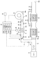
図1に示す燃焼システムは、エンジン10、LNT12、DPF13を備えている。燃焼システムは車両に搭載されたものであり、この車両は、エンジン10の出力を駆動源として走行する。エンジン10は、圧縮自着火式のディーゼルエンジンであり、燃焼に用いる燃料には、炭化水素化合物である軽油を用いている。エンジン10には、このエンジン10に空気を供給する吸気通路と、エンジン10からの排気を放出する排気通路16とが接続されている。排気通路16は、排気マニホールドを介してエンジン10の排気側に接続されている。なお、エンジン10が内燃機関に相当する。
(First embodiment)
The combustion system shown in FIG. 1 includes an
LNT12(Lean NOx Traps)は、窒素酸化物NOxを浄化するNOx吸蔵還元型触媒であり、排気通路16に設けられている。DPF13(Diesel Particulate Filter)は、排気に含まれた微粒子を捕集する微粒子捕集装置であり、LNT12の下流側に配置されている。DPF13にて捕集される微粒子には、粒子状物質PM(Particulate Matter)が含まれている。排気通路16を流れる排気は、LNT12及びDPF13の両方を通過した後に、排気出口16aから放出される。なお、LNT12及びDPF13が排気浄化装置を構成している。
LNT 12 (Lean NOx Traps) is a NOx occlusion reduction catalyst that purifies nitrogen oxides NOx, and is provided in the
燃焼システムは、排気通路16においてLNT12の上流側にオゾンO3を供給するオゾン供給装置30を有している。オゾン供給装置30から排気通路16にオゾンが供給された場合、オゾンにより排気中のNOがNO2に酸化されることでNO2の割合が増加し、その結果、LNT12でのNOx吸蔵率が向上する。オゾン供給装置30は、排気通路16にオゾンを供給する供給状態と、オゾンを供給しない停止状態とに移行可能になっている。
The combustion system has an
また、燃焼システムは、図示しない過給機を有している。過給機は、排気タービン、回転軸及びコンプレッサを備える。排気タービンは、エンジンの排気通路16に配置され、排気の運動エネルギにより回転する。回転軸は、排気タービン及びコンプレッサの各インペラを結合することで、排気タービンの回転力をコンプレッサに伝達する。コンプレッサは、吸気通路に配置されており、吸気を圧縮してエンジン10に過給する。
The combustion system has a supercharger (not shown). The supercharger includes an exhaust turbine, a rotating shaft, and a compressor. The exhaust turbine is disposed in the
オゾン供給装置30は、排気通路16に接続されたオゾン通路31と、空気等のガスに対して放電を発生させることでオゾンを生成する放電リアクタ32と、放電リアクタ32にガスを送るエアポンプ33と、オゾン通路31における排気の逆流を遮断する排気遮断弁34とを有している。なお、排気通路16が、オゾン通路31からオゾンが供給される内燃通路に相当する。
The
また、オゾン供給装置30は、オゾン通路31の内部圧力をガス圧力として検出する圧力センサ35と、オゾン通路31のガス流量を検出する流量センサ36と、ガスの温度を検出する温度センサ37a,37bと、ガスの湿度を検出する湿度センサ38と、オゾンを検出するオゾンセンサ39とを有している。放電リアクタ32の下流側に設けられた下流温度センサ37aは、放電リアクタ32から流れ出るガスの温度を検出し、放電リアクタ32の上流側に設けられた上流温度センサ37bは、放電リアクタ32に流れ込むガスの温度を検出する。
The
オゾン通路31においては、その上流端にエアポンプ33が設けられており、エアポンプ33と排気通路16との間に放電リアクタ32が設けられている。エアポンプ33は、遠心式のエアポンプであり、電動モータにより駆動されるインペラをケース内に収容して構成される。エアポンプ33は、大気を吸入する吸入口33aを有しており、この吸入口33aはケースに形成されている。エアポンプ33は、送風状態に移行する送風部であり、送風量を変化させることが可能になっている。なお、エアポンプ33の吸入口33aがオゾン通路31の上流端を形成している。
An
放電リアクタ32は、放電を発生させることでガスの改質を行うガス改質装置であり、オゾン生成部やオゾナイザと称することもできる。本実施形態の放電リアクタ32は、エアポンプ33から送られた空気中の酸素からオゾンを生成する。この場合、オゾン供給装置30は、放電リアクタ32にて改質されたガスを排気通路16に供給するガス供給装置に相当する。
The
放電リアクタ32は、その内部に流通路42aを形成するハウジング42を備え、流通路42aには複数の電極41が配置されている。これらの電極41は、互いに平行に対向するように配置された平板形状であり、高電圧が印加される電極41と接地電圧の電極41とが交互に配置されている。各電極41は、放電リアクタ32の上流側から下流側に向けて延びている。放電リアクタ32のハウジング42には、エアポンプ33により送風されたガスが流入する。このガスは、ハウジング42内の流通路42aに流入し、電極41間の通路である電極間通路41aを流通する。
The
放電リアクタ32の電極41に電圧が印加されると、電極41から放出された電子が、電極間通路41aのガスに含まれる酸素分子に衝突し、酸素分子から2個の酸素原子が発生する。そして、この酸素原子が他の酸素分子と結合することでオゾンO3が生成される。ここで、電子が酸素分子に衝突した場合、2個の酸素原子が発生するとともに2個の電子が放出され、これら電子が更に別の酸素分子に衝突する。電極41への印加電圧が十分に大きい場合、放電リアクタ32においては、電子雪崩が発生することで加速度的に電子数が増加して放電が開始され、その放電に伴って生成されたオゾンが放電リアクタ32から流れ出ることになる。
When a voltage is applied to the
発明者らは、放電リアクタ32において放電が開始された場合にはガスの温度が短時間で急峻に上昇する、という知見を得た。例えば、図2に示すように、放電が発生するほどに高い電圧がタイミングtaにて電極41に印加された場合、放電リアクタ32に流入するガスの温度がタイミングtaの前後で大きな変化がない。この場合でも、放電リアクタ32から流出するガスの温度はタイミングtaから急激に上昇している。そして、放電が発生している期間においては、流出ガスの温度が流入ガスの温度より継続して高くなっている。また、電極41への電圧印加が開始されてから微小時間だけ経過した後には、放電の開始に伴ってオゾンが生成されることで、オゾン濃度が急激に高くなっている。オゾン濃度が高い状態は、放電が発生している期間において継続される。
The inventors have found that when the discharge is started in the
ここで、酸素分子は、ガスに含まれた気体分子の一種類に過ぎず、放電リアクタ32においては、電子雪崩が発生している場合に電子が衝突しても分解しない気体分子が多数存在する。電子が衝突しても分解しない気体分子は、電子の衝突に伴って振動し、熱を発生する。電子雪崩の発生に伴って放電が開始された場合、熱を発生する気体分子が電子雪崩の発生に伴って多数存在していることで、ガスの温度が短時間で上昇することになる。
Here, the oxygen molecule is only one type of gas molecule contained in the gas, and there are many gas molecules in the
なお、電極41から放電された電子が窒素分子に衝突した場合、窒素分子から2個の窒素原子が発生する。そして、この窒素原子が酸素分子と結合することでNO2が生成される。すなわち、NOxが生成される。また、酸素分子が分解することで発生した酸素原子が窒素分子と結合することで、亜酸化窒素N2Oが笑気ガスとして生成される。ちなみに、放電が開始された場合、N2Oが生成される量は、オゾンが生成される量の1/200程度である。
When electrons discharged from the
放電リアクタ32においては、放電の発生しやすさが内部圧力に応じて変化する。パッシェンの法則によれば、図3に示すように、放電が発生する電圧である火花電圧と気体圧力との関係が曲線で示され、横軸の値がXaからXbに増加した場合に、縦軸の値もYaからYbに増加する。ここで、横軸の値は、対向する電極41の間の離間距離と内部圧力との積であり、離間距離が一定であれば、内部圧力が増加することで火花電圧も大きくなる。換言すれば、内部圧力が低下することで低い電圧で放電が発生しやすくなる。なお、放電リアクタ32の内部圧力は、圧力センサ35により検出されるガス圧力とほぼ同じになっている。
In the
図4に示すように、電極41は、以下に説明する基材44、電極線45および誘電体膜46を有して構成されている。基材44は、誘電体で形成された板状である。基材44には電極線45が設けられ、さらに、電極線45を覆う誘電体膜46が基材44に設けられている。つまり、基材44表面の全体は、印刷された電極線45を内包するように誘電体膜46により覆われている。
As shown in FIG. 4, the
具体的には、図4に示す複数の電極41のうち、両端に位置する電極以外については、基材44の両面に電極線45が印刷されている。電極線45は、基材44表面の全体に分布するように、基材44表面に沿って蛇行して延びる線状である。電極41の断面を表した図4では、同一の基材44上に複数の電極線45が配置されているように見えるが、電極線45は複数に分岐して延びる形状であり、図4で表現される上記複数の電極線45は、平面視においては互いに繋がっている。図4に示す複数の電極41のうち、両端に位置する電極については、基材44の片面に電極線45および誘電体膜46が設けられている。
Specifically, among the plurality of
なお、図4では、電極線45の断面積を模式的に誇張して表現しているため、誘電体膜46と基材44の間に空間が存在するように図示されている。しかし、実際にはこのような空間は存在しておらず、誘電体膜46は、電極線45を内包した状態で基材44に密着している。
In FIG. 4, the cross-sectional area of the
図4に示す4つの電極41のうち、一番下に位置する電極41およびその2つ上に位置する電極41は、先述した印加電極である。また、一番上に位置する電極41およびその2つ下に位置する電極41は、先述した接地電極である。印加電極が有する2つの電極線45にはパルス電圧が印加される。接地電極が有する2つの電極線45はいずれも接地されている。つまり、同一の電極41内に設けられた2つの電極線45は同電位となっている。接地電極の電極線45から放出された電子が、電極間通路41aを通じて印加電極へ向けて移動する。このように移動する電子が電極間通路41aに存在する酸素分子に衝突することにより、オゾンが生成される。
Of the four
ここで、本実施形態に反し、電極線45に換えて板状の電極を用いた場合には、電極間通路41aに生じる電界の強度分布は均一になる。これに対し本実施形態では、線状の電極線45を採用するので、電極間通路41aに生じる電界は電極線45の部分に集中する。電極間通路41aでは、このように電界が集中した部分を起点に放電(種放電)が生じ、その種放電に誘発されて、電解集中していない部分での放電が生じやすくなる。よって、電極線45への印加電圧を高くすることなく、電極間通路41aでの放電を安定して生じさせることができる。この場合、電極間通路41aを、電極41からの放電が発生する放電空間と称することもできる。
Here, contrary to the present embodiment, when a plate-like electrode is used instead of the
さらに本実施形態では、電極線45を覆う誘電体膜46を備えるので、印加電極へ向けて移動した電子は、印加電極の誘電体膜46の表面に沿って移動するといった、沿面放電が生じるようになる。すると、放電された電子が、電極間通路41aに存在する酸素に接触する機会が増大するので、酸素からオゾンが生成される割合が向上する。
Further, in this embodiment, since the
図4に示すように、接地電極が有する電極線45はグランドに接続され、印加電極が有する電極線45はリアクタ給電部48に接続されている。リアクタ給電部48は、車両に搭載されたバッテリ等の電源部48aと、電源部48aの電圧を変換する変圧部48bとを有しており、電源部48aが変圧部48bを介して電極線45に接続されている。変圧部48bは、電源部48aから供給される低圧電力を段階的に昇圧又は降圧することが可能になっている。例えば、12Vの電圧を15kVまで昇圧することが可能であり、その昇圧幅を100V〜500Vまで変更可能になっている。
As shown in FIG. 4, the
リアクタ給電部48は、電源部48aの直流電圧からパルス電圧を生成するパルス回路を有している。パルス回路は、電源部48aと変圧部48bとの間に設けられており、変圧部48bはパルス電圧の変圧を行う。パルス電圧が電極41に印加されることで放電が開始された場合、そのパルス電圧に応じた電流が印加電極と接地電極との間を流れる。この電流は、放電による電荷の動きに起因して短時間で増減を繰り返すことで、多くのノイズを含むことになる。
The reactor
また、リアクタ給電部48は、電源部48aから電極41への電力供給を停止させることが可能なスイッチ部を有している。スイッチ部は通電状態と遮断状態とに移行可能になっており、スイッチ部が通電状態にある場合に電極41に電圧が印加され、スイッチ部が遮断状態にある場合に電極41に電圧が印加されない。
In addition, the reactor
なお、リアクタ給電部48は、電源部48aの直流電圧から交流電圧を生成する交流回路を有していてもよい。この場合、交流回路は、電源部48aと変圧部48bとの間に設けられており、変圧部48bは交流電圧の変圧を行う。また、リアクタ給電部48において、パルス電圧や交流電圧のいずれが生成される場合でも、これら電圧がバースト電圧とされていてもよい。
The reactor
ここで、電極41においては、基材44、電極線45及び誘電体膜46がいずれもセラミック等の誘電体により形成されており、パルス電圧を用いた放電により低温プラズマが発生することになる。放電リアクタ32においては、低温プラズマが発生してもガスが例えば200度より高温にならず、生成されたオゾンが高温のガスにより分解されるということが生じにくくなっている。
Here, in the
これに対して、例えば電極41が金属材料により形成された構成では、放電を発生させるためにパルス電圧ではなく直流電圧を使用せざるを得ず、直流電圧による放電では熱プラズマが発生することになる。放電リアクタ32においては、熱プラズマが発生することで、オゾンが分解されるほどにガスの温度が上昇する。このため、放電に伴ってオゾンが生成されたとしても、そのオゾンが熱で分解されてしまう。
On the other hand, for example, in a configuration in which the
図1に戻り、排気遮断弁34は、機械式や電磁駆動式の開閉弁であり、オゾン通路31において放電リアクタ32と排気通路16との間に設けられている。排気遮断弁34は、通気を可能にする開状態と、通気を遮断する閉状態とに移行可能になっており、閉状態が遮断状態に相当する。排気遮断弁34が開状態にある場合、オゾン通路31の通路流量は排気遮断弁34の開度に応じて調整される。オゾン通路31の通路流量は、排気遮断弁34が全開状態にある場合に最大になる。なお、排気遮断弁34が排気遮断部に相当する。
Returning to FIG. 1, the
圧力センサ35は、オゾン通路31において放電リアクタ32と排気遮断弁34との間に設けられている。具体的には、圧力センサ35は、放電リアクタ32寄りの位置に配置されている。この場合、圧力センサ35の検出結果に、排気遮断弁34の開閉に伴う圧力変化が反映されやすくなっている。なお、圧力センサ35が圧力検出部に相当する。
The
流量センサ36は、エアポンプ33と放電リアクタ32との間に設けられており、エアポンプ33からのガスの吐出量を検出可能になっている。具体的には、流量センサ36は、エアポンプ33寄りの位置に配置されている。この場合、流量センサ36の検出結果に、エアポンプ33の駆動及び停止に伴うガスの流量変化が反映されやすくなっている。なお、流量センサ36が流量検出部に相当する。
The
下流温度センサ37aは、放電リアクタ32と排気遮断弁34との間において、放電リアクタ32寄りの位置に設けられている。下流温度センサ37aは、放電リアクタ32及び電源部48aに対して電気的に絶縁された状態になっている。例えば、下流温度センサ37aは、合成樹脂材料等の絶縁体を介してオゾン通路31やハウジング42に取り付けられている。また、下流温度センサ37aは、放電リアクタ32の電極間通路41aに対して絶縁されることで電気的に隔離された状態になっている。このため、下流温度センサ37aは、オゾン通路31を形成する配管やハウジング42、電極41の温度から影響を受けにくい状態で、放電リアクタ32から流れ出たガスの温度を検出することになる。
The
上流温度センサ37bは、放電リアクタ32とエアポンプ33との間において、放電リアクタ32寄りの位置に設けられている。湿度センサ38は、放電リアクタ32と湿度センサ38との間に配置されており、放電リアクタ32に流れ込むガスの湿度を検出する。オゾンセンサ39は、オゾン通路31において排気遮断弁34と排気通路16との間に設けられており、排気通路16寄りの位置に配置されている。
The
排気通路16において、オゾン通路31とLNT12との間にはミキサー16bが設けられている。ミキサー16bは、オゾン通路31から供給されたオゾンと排気とを混合させる混合部であり、ミキサー16bの下流側においては、オゾンによる排気中のNOxの酸化が促進される。
In the
燃焼システムの電気的な構成について説明する。燃焼システムは、制御装置としてのECU60を有している。ECU60は、プロセッサ61a、RAM41b、メモリ61c及び情報の入出力を行うインターフェース41dを有している。メモリ61cは、書き換え可能な不揮発性の記憶媒体であり、記憶部に相当する。
The electrical configuration of the combustion system will be described. The combustion system has an
ECU60は、アクセル開度やエンジン負荷、エンジン回転速度等に基づき、燃料噴射弁の噴射量や噴射圧力、過給機の過給圧力、エンジン10への吸気量の制御を行う。ここで、ECU60にはアクセル開度センサ66が接続されている。アクセル開度センサ66は、運転者により操作されるアクセルペダルに設けられており、アクセルペダルの操作量をアクセル開度として検出可能になっている。この場合、アクセル開度は、アクセルペダルの操作量に基づいて取得される操作パラメータの1つであり、ECU60は、操作パラメータに基づいてエンジン10の出力制御を行う。
The
ECU60には、圧力センサ35、流量センサ36、下流温度センサ37a、湿度センサ38、オゾンセンサ39、排気温度センサ51、排気圧センサ52、NOxセンサ53、PMセンサ54、A/Fセンサ55が接続されている。センサ51〜55は排気通路16に設けられている。排気温度センサ51は、LNT12の上流側及び下流側のそれぞれに配置され、A/Fセンサ55は、LNT12の上流側に配置されている。排気圧センサ52は、DPF13に対して設けられ、排気通路16においてDPF13の上流側と下流側との圧力差を検出する。また、排気圧センサ52は、排気通路16の内部圧力を排気圧力として検出可能になっている。なお、図1においては、センサ51〜55とECU60との電気的な接続線の図示を省略している。
Connected to the
ECU60には、エアポンプ33、排気遮断弁34及びリアクタ給電部48がアクチュエータとして接続されている。ECU60は、指令信号を出力することでこれらアクチュエータの動作制御を行う。例えば、リアクタ給電部48については、電極41への電圧印加の状態を制御することで、放電リアクタ32によるオゾンの生成量や生成率を調整する。また、エアポンプ33については、デューティ制御によりエアポンプ33への供給電力量を制御することでエアポンプによる送風量を調整する。さらに、排気遮断弁34については、排気遮断弁34の開度を増減することでオゾン通路31のガス流量やガス圧力を調整する。
The
ECU60は、メモリ61cに記憶された制御プログラムをプロセッサ61aにより実行することで、図4に示すNOx酸化部71、DPF再生部72、捕集再生部63及び濃度変更部64を、機能ブロックとして構築する。
The
ECU60は、排気中のNOxの酸化を促進させるNOx酸化部71と、DPF13が捕集したPMを除去するべくDPF再生を行うDPF再生部72とを有している。DPF再生部72は、排気温度を上昇させる処理を行うことでDPF13でのPMの燃焼を促進する。排気温度を上昇させる処理としては、エンジン10での燃料噴射量を増加させる処理や、オゾン供給装置30を供給状態に移行させてオゾンをDPF13に供給する処理などが挙げられる。NOx酸化部71は、オゾン供給装置30を供給状態に移行させる処理を行う。
The
また、ECU60は、放電リアクタ32において放電が開始される放電開始電圧Vdisを探索する放電探索部73と、電極41への印加電圧を可変設定することが可能な電圧設定部74とを有している。放電探索部73は、電極41により放電が発生する電圧のうち極力小さい電圧を放電開始電圧Vdisとして、この放電開始電圧Vdisをメモリ61cに記憶する。メモリ61cにおいては、放電開始電圧Vdisがガス圧力に対応させて記憶されている。電圧設定部74は、変圧部48bの動作制御を行うことで、電極41への印加電圧を増減させることが可能になっている。また、電圧設定部74は、リアクタ給電部48の動作制御を行うことで、電極41への電圧の印加を停止させることも可能になっている。
The
ECU60は、オゾン供給装置30のオゾン生成を管理するオゾン管理処理を行う。ここでは、オゾン管理処理について図5を参照しつつ説明する。このオゾン管理処理は、エンジン10の運転期間中に所定周期で繰り返し実行される。なお、ECU60は、オゾン管理処理をプロセッサ61aにより実行する機能を有しており、この機能が放電探索部73に相当する。また、ECU60が放電制御装置に相当し、オゾン管理処理の手順が放電制御方法に相当する。
The
図5において、ステップS101では、排気通路16にオゾンを供給するか否かを判定する。すなわち、オゾン供給装置30を供給状態に移行させるか否かを判定する。ここでは、LNT12にNOx吸着を行わせる必要があるか否かを判定し、NOx吸着を行わせる必要がある場合に、オゾンの供給を行うとしてステップS102に進む。なお、LNT12にNOx吸着を行わせる場合としては、排気温度が所定温度より高い場合などが挙げられる。
In FIG. 5, in step S <b> 101, it is determined whether or not ozone is supplied to the
ステップS102では、エアポンプ33の運転を開始し、その後、ステップS103にて、排気遮断弁34を開状態に移行させる。この場合、エアポンプ33の出力を最大に設定し、排気遮断弁34を全開状態に設定する。ステップ104では、メモリ61cに記憶されている放電開始電圧Vdisを読み込み、この放電開始電圧Vdisを、放電リアクタ32にてオゾンを生成させるための生成電圧Vとする。この場合、電極41への印加電圧が生成電圧Vになるように電圧設定部74に電圧設定を行わせる。また、ステップS104では、圧力センサ35の検出信号に基づいてガス圧力を取得し、このガス圧力に対応した放電開始電圧Vdisをメモリ61cから読み込む。
In step S102, the operation of the
ステップS105では、リアクタ給電部48を動作させることで電極41に生成電圧Vを印加する。ここでは、圧力センサ35の検出信号に基づいてガス圧力を取得し、メモリ61cから
ステップS106では、放電リアクタ32よりも下流においてオゾン通路31を流れるオゾンが不足しているか否かを判定する。ここでは、オゾン通路31から排気通路16に流れ込むガスのオゾン濃度をオゾンセンサ39の検出信号に基づいて算出し、オゾン濃度が基準値より小さいか否かを判定する。オゾン濃度が基準値より小さい場合、放電リアクタ32において放電が発生していないことに起因してオゾンが不足しているとして、ステップS107に進む。なお、ステップS105にて電極41への電圧印加を開始した後、放電リアクタ32から流れ出たガスがオゾンセンサ39に到達するのに要する時間だけ待機してからステップS106の判定処理を行う。
In step S <b> 105, the generated voltage V is applied to the
ステップS107では、放電リアクタ32において放電を発生させるべく、生成電圧Vを増加させる。ここでは、変圧部48bの動作制御を行うことで生成電圧Vを上昇値Vaだけ増加させる。この場合、電極41への印加電圧が新たな生成電圧Vになるように電圧設定部74に電圧設定を行わせる。これにより、生成電圧Vが増加した分だけ放電リアクタ32において放電が発生しやすくなる。生成電圧Vを増加させた後、ステップS106に戻り、オゾンが不足しているか否かの判定を再び行う。この場合、放電リアクタ32において放電が発生するまでステップS106,S107を繰り返し行うことになる。なお、ステップS105と同様に、ステップS107の処理を行った後、放電リアクタ32から流れ出たガスがオゾンセンサ39に到達するのに要する時間だけ待機してからステップS106の判定処理を行う。
In step S107, the generated voltage V is increased in order to generate a discharge in the
ステップS101にて排気通路16にオゾンを供給しない場合、ステップS108に進み、エンジン回転速度や目標噴射量、アクセル開度センサ66の検出信号等に基づいて、エンジン10がアイドリング状態にあるか否かを判定する。ステップS109では、排気圧センサ52の検出信号に基づいて排気圧力を取得し、この排気圧があらかじめ定められた基準値より小さいか否かを判定する。ここでは、排気圧力が基準値より小さい状態が所定時間だけ継続している場合に、YES判定とする。YES判定される場合としては、車両が速度変化の少ない状態で低速走行や高速走行をしている場合が挙げられる。基準値は、例えば、エアポンプ33の出力が最大になっている場合に排気通路16からオゾン通路31に排気が逆流しない程度の排気圧力の値に設定されている。
When ozone is not supplied to the
ステップS108,S109のうち一方がYES判定の場合、ステップS110に進み、放電開始電圧Vdisを探索する探索処理を行う。探索処理については、図6を参照しつつ説明する。 When one of steps S108 and S109 is YES, the process proceeds to step S110, and a search process for searching for the discharge start voltage Vdis is performed. The search process will be described with reference to FIG.
図6において、ステップS201では、エアポンプ33の運転を開始し、その後、ステップS202にて、排気遮断弁34を開状態に移行させる。そして、ステップS203では、圧力センサ35の検出信号に基づいてガス圧力を取得し、ステップS204では、下流温度センサ37aの検出信号に基づいて、放電リアクタ32から流出するガスの温度をガス温度Tとして取得する。このステップS204にて取得したガス温度Tは、電極41に電圧が印加されていない場合に放電リアクタ32から流出するガスの温度である。
In FIG. 6, in step S201, the operation of the
なお、エアポンプ33の運転を開始し、排気遮断弁34を開状態に移行させた後、エアポンプ33による送風が安定するまで待機してからステップS203,S204の取得処理を行う。また、送風が安定した後、これらステップS203,S204では、ガス圧力及びガス温度Tの取得を複数回行う。このため、放電が開始される前のガス圧力やガス温度Tの取得精度が高められる。
After the operation of the
ここで、エアポンプ33については、排気通路16からオゾン通路31への排気の逆流が発生しない範囲で極力小さい風量を排気圧力に基づいて算出し、この風量になるように出力を設定する。ここで、探索処理は繰り返し行われるものであり、ガス圧力が前回の探索処理とは異なる値になるように排気遮断弁34の開度を設定する。これにより、メモリ61cには、異なるガス圧力に対応する放電開始電圧Vdisが複数記憶されていくことになる。
Here, with respect to the
ステップS205では、放電開始電圧Vdisを探索するための探索電圧Vsを、あらかじめ定められた初期電圧Vbaseに設定し、ステップS206では、探索電圧Vsを増加させる場合の増加量を追加値Vaddとして設定する。このステップS205では、電極41への印加電圧が探索電圧Vsになるように電圧設定部74に電圧設定を行わせる。
In step S205, a search voltage Vs for searching for the discharge start voltage Vdis is set to a predetermined initial voltage Vbase, and in step S206, an increase amount when the search voltage Vs is increased is set as an additional value Vadd. . In step S205, the voltage setting unit 74 sets the voltage so that the applied voltage to the
これら初期電圧Vbase及び追加値Vaddについては、オゾン通路31のガス温度やガス圧力などに基づいて設定する。ここで、放電リアクタ32の内部においては、ガスの温度が高いほど放電に必要な電圧が小さくなりやすく、ガスの圧力が小さいほど放電に必要な電圧が小さくなりやすい。したがって、例えば、ガス温度が高いほど初期電圧Vbaseや追加値Vaddを小さい値に設定し、ガス圧力が小さいほど初期電圧Vbaseや追加値Vaddを小さい値に設定する。本実施形態では、初期電圧Vbaseを例えば8kVに設定し、追加値Vaddを例えば0.5kVに設定する。なお、前回の探索処理において探索された放電開始電圧Vdisを初期電圧Vbaseとして設定してもよい。
The initial voltage Vbase and the additional value Vadd are set based on the gas temperature and gas pressure in the
ステップS207では、探索の回数を示すカウンタnをn=0に設定する。ステップS208では、リアクタ給電部48を動作させることで電極41への探索電圧Vsの印加を開始する。
In step S207, a counter n indicating the number of searches is set to n = 0. In step S208, application of the search voltage Vs to the
ステップS209では、下流温度センサ37aの検出信号に基づいてガス温度Tを取得する。このステップS208にて取得したガス温度Tは、電極41に電圧が印加されている場合に放電リアクタ32から流出するガスの温度である。ステップS210では、ステップS209にて取得したガス温度Tから、ステップS204にて取得したガス温度Tを引いた値を、変化温度ΔTとして算出する。なお、変化温度ΔTが上昇量に相当する。
In step S209, the gas temperature T is acquired based on the detection signal of the
ステップS211では、変化温度ΔTが放電開始を示す判定値Aよりも大きいか否かを判定する。ここでは、判定値Aを、試験やシミュレーション等により得られたデータを用いて、オゾン通路31のガス流量やガス圧力などに基づいて設定する。ここで、放電開始に伴ってガス温度Tが上昇したとしても、ガス流量が大きいほどその上昇量は小さくなりやすい。また、ガス圧力が小さいほど電子が分子に衝突する確率が低下することに起因して、放電開始に伴うガス温度Tの上昇量は小さくなりやすい。したがって、例えば、ガス流量が大きいほど判定値Aを小さい値に設定し、ガス圧力が小さいほど判定値Aを小さい値に設定する。
In step S211, it is determined whether or not the change temperature ΔT is larger than a determination value A indicating the start of discharge. Here, the determination value A is set based on the gas flow rate, gas pressure, and the like of the
なお、ステップS208にて探索電圧Vsの印加を開始した後、放電リアクタ32から流れ出たガスが下流温度センサ37aに到達するのに要する時間を待機時間として待機してからステップ211の判定処理を行う。この場合、ステップS209,S210では、待機時間においてガス温度T及び変化温度ΔTの取得を複数回ずつ行う。このため、探索電圧Vsの印加が開始された後のガス温度Tや変化温度ΔTの取得精度が高められる。
After starting application of the search voltage Vs in step S208, the determination process in
変化温度ΔTが判定値Aより大きくない場合、ステップS212に進み、カウンタnをインクリメントする。ステップS213では、初期電圧Vbase、追加値Vadd及びカウンタnを用いて探索電圧Vsを増加させる。具体的には、追加値Vaddとカウンタnとの積を初期電圧Vbaseに加えた値を算出し、この算出値を探索電圧Vsとして設定する。この場合、電極41への印加電圧が新たな探索電圧Vsになるように電圧設定部74に電圧設定を行わせる。
When the change temperature ΔT is not greater than the determination value A, the process proceeds to step S212, and the counter n is incremented. In step S213, the search voltage Vs is increased using the initial voltage Vbase, the additional value Vadd, and the counter n. Specifically, a value obtained by adding the product of the additional value Vadd and the counter n to the initial voltage Vbase is calculated, and this calculated value is set as the search voltage Vs. In this case, the voltage setting unit 74 performs voltage setting so that the voltage applied to the
ステップS213の処理後、ステップS209〜S211の処理を再び行う。この場合、ステップS211にて変化温度ΔTが判定値Aより大きいと判定されるまで、増加させる量を追加値Vaddとして探索電圧Vsを段階的に増加させることになる。 After the process of step S213, the processes of steps S209 to S211 are performed again. In this case, until the change temperature ΔT is determined to be larger than the determination value A in step S211, the search voltage Vs is increased stepwise with the amount to be increased as the additional value Vadd.
なお、ステップS213の処理の後に行うステップS211においては、今回のステップS210の処理にて取得したガス温度Tから、前回のステップS210の処理にて取得したガス温度Tを引いた値を、変化温度ΔTとして算出する。また、ステップS213にて探索電圧Vsを増加させた後、ステップS208にて探索電圧Vsの印加を開始した後と同様に、待機時間だけ待機してからステップS211の判定処理を行い、この待機時間においてステップS209,S210にてガス温度T及び変化温度ΔTの取得を複数回ずつ行う。 In step S211 performed after the process of step S213, a value obtained by subtracting the gas temperature T acquired in the process of the previous step S210 from the gas temperature T acquired in the process of the present step S210 is a change temperature. Calculated as ΔT. Further, after the search voltage Vs is increased in step S213, after the application of the search voltage Vs is started in step S208, the determination process in step S211 is performed after waiting for the standby time. In steps S209 and S210, the gas temperature T and the change temperature ΔT are acquired a plurality of times.
ステップS211にて変化温度ΔTが判定値Aより大きい場合、放電リアクタ32にて放電が開始されたとして、ステップS214に進む。ステップS214では、カウンタnについてn=0であるか否かを判定する。n=0でない場合、ステップS215に進み、現在の探索電圧Vsを放電開始電圧Vdisとして、ステップS203にて取得したガス圧力と、ステップS204にて取得した放電未発生のガス温度とに対応付けて、メモリ61cに記憶する。また、ステップS215では、リアクタ給電部48を動作させることで電極41への探索電圧Vsの印加を停止する。
When the change temperature ΔT is larger than the determination value A in step S211, it is determined that the discharge is started in the
ここで、n=0でない場合は、図7に示すように、初期電圧Vbaseが探索電圧Vsとして電極41に印加されても変化温度ΔTが判定値Aより大きくならなかった場合である。この場合、タイミングtaにて電極41への電圧印加が開始された後、変化温度ΔTが判定値Aより大きくなるまで探索電圧Vsが追加値Vaddずつ増加される。そして、探索電圧Vsが放電が発生するほどに大きな値に設定されたタイミングtbにてガス温度Tが上昇し始め、変化温度ΔTが判定値Aより大きくなる。また、ステップS211の判定処理が行われる前に待機時間が確保されることで、探索電圧Vsが変更されずに保持時間Thだけ保持される。
Here, the case where n is not 0 is a case where the change temperature ΔT does not become larger than the determination value A even when the initial voltage Vbase is applied to the
図6の説明に戻り、ステップS214にて、カウンタnについてn=0であると判定された場合、初期電圧Vbaseで放電が発生したとして、ステップS216に進む。初期電圧Vbaseで放電が発生した場合、初期電圧Vbaseよりも小さい印加電圧で放電が発生する可能性があることになる。そこで、ステップS216にて、リアクタ給電部48からの給電を停止させることで電極41への電圧印加を停止させ、ステップS217にて、探索電圧Vsを初期電圧Vbaseより小さい電圧に設定する。ここでは、探索電圧Vsを初期電圧Vbaseよりも削減値Vcutだけ減少させる。この場合、電極41への印加電圧が新たな探索電圧Vsになるように電圧設定部74に電圧設定を行わせる。削減値Vcutについては、初期電圧Vbaseや追加値Vaddと同様に、オゾン通路31のオゾン温度やガス圧力などに基づいて設定する。本実施形態では、削減値Vcutを例えば追加値Vaddよりも大きい1.5kVに設定する。
Returning to the description of FIG. 6, if it is determined in step S214 that n = 0 for the counter n, it is determined that discharge has occurred at the initial voltage Vbase, and the process proceeds to step S216. When the discharge occurs at the initial voltage Vbase, the discharge may occur at an applied voltage lower than the initial voltage Vbase. Therefore, in step S216, voltage supply to the
ステップS217の後、ステップS208〜S215の処理を行う。ここで、ステップS216にて電圧印加を停止した後、初期電圧Vbaseで放電が開始されたことで上昇したガス温度Tが低下して安定するのに要する時間を待機時間として待機してからステップS208の電圧印加処理を行う。このように、ガス温度Tが安定するまで待機することで、再び放電が開始された場合のガス温度Tの変化が明確になりやすい。この結果、態様が探索電圧Vsを減少させて放電開始電圧Vdisの探索を再度行う場合でも、その探索精度が低下しにくい。 After step S217, steps S208 to S215 are performed. Here, after the voltage application is stopped in step S216, after waiting for the time required for the gas temperature T, which has risen as a result of the discharge to start at the initial voltage Vbase, to decrease and stabilize, the standby time is set, and then step S208 is performed. The voltage application process is performed. Thus, by waiting until the gas temperature T becomes stable, the change in the gas temperature T when the discharge is started again becomes clear. As a result, even when the mode decreases the search voltage Vs and searches for the discharge start voltage Vdis again, the search accuracy is unlikely to decrease.
なお、ECU60は、ステップS203,S204,S208,S209,S211,S215,S216の処理を実行する機能を有しており、ステップS203の処理を実行する機能が圧力取得部に相当する。ステップS204,S209の処理を実行する機能が温度取得部に相当し、ステップS208の処理を実行する機能が印加実行部に相当し、ステップS211の処理を実行する機能が温度判定部に相当する。ステップS215の処理を実行する機能が記憶実行部に相当し、ステップS216の処理を実行する機能が初期停止部に相当する。
The
ここで、ステップS214にてn=0であると判定された場合は、図8に示すように、初期電圧Vbaseが探索電圧Vsとして電極41に印加されることで放電が開始した場合である。この場合、電極41への探索電圧Vsの印加が開始されたタイミングtaにおいて、ガス温度Tが上昇し始め、変化温度ΔTが判定値Aより大きくなる。そして、この探索電圧Vsが保持時間Thだけ確保され、その後、電極41への探索電圧Vsの印加が停止時間Toffだけ停止される。この停止時間Toffは、ステップS216,S217の後にステップS208の電圧印加処理が行われる前に確保された待機時間に応じた長さになっている。
Here, when it is determined in step S214 that n = 0, the discharge is started by applying the initial voltage Vbase to the
探索電圧Vsの印加停止から停止時間Toffが経過したタイミングtcにおいて、初期電圧Vbaseより削減値Vcutだけ小さい探索電圧Vsが電極41に印加される。これにより、放電開始電圧Vdisの探索が再び開始される。図8には、放電開始電圧Vdisの再検索において、探索電圧Vsを複数段階で増加させた後に放電が開始した例を図示している。この場合、探索電圧Vsが放電が発生するほどに大きな値に設定されたタイミングtdにてガス温度Tが上昇し始め、変化温度ΔTが判定値Aより大きくなる。
The search voltage Vs that is smaller than the initial voltage Vbase by the reduction value Vcut is applied to the
ここで、初期電圧Vbaseが探索電圧Vsとして電極41に印加されることで放電が発生した場合、電極41への電圧印加を停止させるのではなく、電極41への電圧印加を継続しつつ、探索電圧Vsを段階的に減少させる方法が考えられる。これに対して、発明者らは、探索電圧Vsを減少させた場合には、探索電圧Vsの増加に伴って放電が開始する電圧を超えて探索電圧Vsが小さくなった状態でも放電が維持される、という知見を得た。すなわち、電極41への印加電圧と放電との関係にヒステリシスが生じるという知見を得た。このため、探索電圧Vsを減少させる方法では、仮に放電が終了する電圧を取得することができたとしても、その電圧を生成電圧Vとして電極41に印加した場合に放電が開始されないことが懸念される。
Here, when the discharge is generated by applying the initial voltage Vbase to the
ここまで説明した第1実施形態の作用効果を以下に説明する。 The operational effects of the first embodiment described so far will be described below.
第1実施形態によれば、探索電圧Vsの増加に応じたガス温度Tの変化温度ΔTが判定値Aより大きいか否かの判定がステップS211にて行われることで、探索電圧Vsにより放電開始電圧Vdisの探索が行われる。この場合、ガス圧力やガス流量、放電リアクタ32の個体差、放電リアクタ32の経年劣化等により放電の発生電圧が異なっていたとしても、その電圧を放電開始電圧Vdisとして精度良く取得することができる。このため、排気通路16でのNOxの酸化等を目的として放電リアクタ32によりオゾンを発生させる場合に、放電開始電圧Vdisを生成電圧Vとして電極に印加したにもかかわらず放電が開始せずにオゾンが生成されないということを抑制できる。また、この場合、生成電圧Vが過剰に高いことでオゾンの生成量に対する消費電力が大きく、電力を浪費してしまうことを抑制できる。以上により、放電リアクタ32に流入したガスの改質を確実に行いつつ、電力効率の向上を図ることができる。
According to the first embodiment, whether or not the change temperature ΔT of the gas temperature T according to the increase in the search voltage Vs is larger than the determination value A is determined in step S211, so that the discharge is started by the search voltage Vs. A search for voltage Vdis is performed. In this case, even if the discharge generation voltage differs due to gas pressure, gas flow rate, individual differences of the
なお、エンジン10の排気中のNOxは排気規制対象になっており、年々厳しくなることが予想される。この対策として本実施形態では後処理装置としてLNT12が車両に搭載されている。ここで、ディーゼルエンジンの後処理装置としてはLNT12の他にも尿素SCR(Selective Catalytic Reduction)があり、ガソリンエンジンの後処理装置としては3元触媒がある。これら後処理装置においては、NOxを浄化する上で排気温度が重要な役割を担っており、排気がある程度の温度に達していないとNOx浄化触媒の活性が高くなりにくい等の理由によりNOxの浄化性能が発揮されにくい。このため、将来のNOx浄化にとって排気温度が低い状態への対策が重要な課題である。
Note that NOx in the exhaust of the
この課題を更に分析すると、NOx浄化触媒の活性が高くなっていないことで、NOx浄化触媒によるNOx浄化の過程で必要なNOの酸化が行われにくいことが原因になっており、排気温度が低い状態でNOを酸化させる技術が重要な技術になる。放電リアクタ32は、酸素分子からオゾンを生成するものであり、空気を原料としてオゾンを生成することができる。また、オゾンは低温でもNOに直接反応してそのNOを酸化させることができるため、排気温度が低い状態への対策として有用な技術である。
When this problem is further analyzed, the NOx purification catalyst is not highly active, which is why it is difficult to oxidize NO necessary in the process of NOx purification by the NOx purification catalyst, and the exhaust temperature is low. Technology that oxidizes NO in a state becomes an important technology. The
また、上述したように、放電開始電圧Vdisを探索することで生成電圧Vを極力小さい値にすることが可能であるため、放電リアクタ32やリアクタ給電部48の大型化を抑制することができる。これは、電極41への印加電圧が大きいほど放電リアクタ32やリアクタ給電部48に付与する絶縁構造が大型化したり、高電圧を生成するために変圧部48bが大型化したりしやすくなるためである。さらに、放電に必要な電圧はガス温度やガス圧力、ガスの組成、放電リアクタ32、リアクタ給電部48のばらつきによっても変わるため、確実に放電させるにはより高い電圧を設定することになる。このため、放電リアクタ32やリアクタ給電部48に対する絶縁性の要求が高くなり、これら放電リアクタ32やリアクタ給電部48が大型化することになる。
Further, as described above, since the generated voltage V can be made as small as possible by searching for the discharge start voltage Vdis, it is possible to suppress an increase in the size of the
第1実施形態によれば、放電開始電圧Vdisの探索に際して、探索電圧Vsが段階的に増加されるため、その探索電圧Vsを保持時間Thだけ保持することが可能になる。このため、現在の探索電圧Vsで放電が発生し始めたにもかかわらず、その放電の発生が変化温度ΔTに反映される前のタイミングで探索電圧Vsが増加されてしまう、ということを回避できる。この場合、放電を発生させることが可能な電圧のうち極力小さい電圧を放電開始電圧Vdisとして探索されることになるため、オゾンの生成量に対する消費電力を低減することができる。 According to the first embodiment, when searching for the discharge start voltage Vdis, the search voltage Vs is increased stepwise, so that the search voltage Vs can be held for the holding time Th. For this reason, it can be avoided that the search voltage Vs is increased at a timing before the occurrence of the discharge is reflected in the change temperature ΔT, even though the discharge starts to occur at the current search voltage Vs. . In this case, the smallest possible voltage among the voltages capable of generating discharge is searched for as the discharge start voltage Vdis, so that it is possible to reduce power consumption relative to the amount of ozone generated.
第1実施形態によれば、放電開始電圧Vdisの探索に際して初期電圧Vbaseから開始されるため、例えば探索電圧Vsが「0」から開始される構成に比べて、探索時間を短縮できる。また、本実施形態のように探索電圧Vsが段階的に増加される構成では、追加値Vaddを小さくするほど探索精度が向上するが、追加値Vaddを小さくするほど探索時間が長くなってしまう。これに対して、初期電圧Vbaseが極力高い電圧に設定されることで、探索精度を向上させつつ、探索時間の長期化を抑制することができる。 According to the first embodiment, since the initial voltage Vbase is started when searching for the discharge start voltage Vdis, for example, the search time can be shortened compared to a configuration in which the search voltage Vs starts from “0”. Further, in the configuration in which the search voltage Vs is increased stepwise as in the present embodiment, the search accuracy is improved as the additional value Vadd is decreased, but the search time is increased as the additional value Vadd is decreased. On the other hand, by setting the initial voltage Vbase as high as possible, the search accuracy can be improved and the search time can be prevented from being prolonged.
第1実施形態によれば、初期電圧Vbaseを探索電圧Vsとして電極41に印加することで放電が発生した場合、電極41への探索電圧Vsの印加が一旦停止された後に、探索電圧Vsを減少させた状態で電極41への探索電圧Vsの印加が再開される。このため、例えば電極41への探索電圧Vsの印加が停止されずに探索電圧Vsを減少させた場合とは異なり、放電と電圧との関係に生じるヒステリシスを無視することができる。したがって、探索電圧Vsの減少に伴って放電開始電圧Vdisの探索精度が低下するということを抑制できる。
According to the first embodiment, when discharge is generated by applying the initial voltage Vbase to the
第1実施形態によれば、探索処理により探索された放電開始電圧Vdisがガス圧力に対応させてメモリ61cに記憶されている。このため、放電が開始される電圧がガス圧力に応じて変化するとしても、そのガス圧力に応じた放電開始電圧Vdisを生成電圧Vとして選択することで、排気通路16でのNOxの酸化等を目的としたオゾン生成を確実に実施できる。
According to the first embodiment, the discharge start voltage Vdis searched for by the search process is stored in the memory 61c in correspondence with the gas pressure. For this reason, even if the voltage at which discharge starts changes according to the gas pressure, by selecting the discharge start voltage Vdis according to the gas pressure as the generated voltage V, oxidation of NOx in the
第1実施形態によれば、排気圧力が基準値より小さい場合にステップS110の探索処理が行われるため、エアポンプ33の出力を極力小さく抑えることができる。排気がオゾン通路31を逆流しない程度に排気圧力が低い場合には、エアポンプ33の出力が小さいほどオゾン通路31のガス圧力が小さくなる。この場合、放電リアクタ32にて放電が発生する電圧が小さくなりやすいため、リアクタ給電部48から電極41に印加する高電圧の低減化を図ることができる。これにより、電力消費量を抑えることや、リアクタ給電部48での高電圧生成に際して安全性を高めることが可能になる。
According to the first embodiment, when the exhaust pressure is smaller than the reference value, the search process in step S110 is performed, so that the output of the
第1実施形態によれば、エンジン10がアイドリング状態にある場合にステップS110の探索処理が行われるため、放電開始電圧Vdisの探索精度を高めることができる。これは、エンジン10がアイドリング状態にある場合には排気圧力の変化が小さいことに起因して、オゾン通路31のガス流量の変化が小さく、ガス温度Tが変化しにくい状態にあるためである。
According to the first embodiment, when the
(第2実施形態)
上記第1実施形態では、放電開始電圧Vdisの探索に際して探索電圧Vsが段階的に増加されていたが、第2実施形態では、探索電圧Vsが連続的に増加される。本実施形態では、上記第1実施形態との相違点を中心に、探索処理について図9、図10を参照しつつ説明する。
(Second Embodiment)
In the first embodiment, the search voltage Vs is increased step by step when searching for the discharge start voltage Vdis. In the second embodiment, the search voltage Vs is continuously increased. In the present embodiment, the search process will be described with reference to FIGS. 9 and 10 with a focus on differences from the first embodiment.
図9において、ステップS301では、放電開始電圧Vdisの探索を行うための準備処理を行う。ここでは、上記第1実施形態のステップS201〜S205と同じ処理を行う。このため、ステップS302の処理を行う前の段階で、エアポンプ33から供給されたガスがオゾン通路31を流れている。また、探索電圧Vsが初期電圧Vbaseに設定されている。
In FIG. 9, in step S301, a preparation process for searching for the discharge start voltage Vdis is performed. Here, the same processing as steps S201 to S205 of the first embodiment is performed. For this reason, the gas supplied from the
ステップS302では、探索電圧Vsを連続的に増加させる場合について、単位時間当たりの増加量を増加率Bとして設定する。増加率Bについては、現在のオゾン通路31のガス温度Tやガス圧力、ガス流量などに基づいて設定する。例えば、ガス流量が大きいほど放電発生に伴うガス温度Tの上昇量が小さくなり、変化温度ΔTを用いて放電発生の判定を行う際の判定精度が低下しやすい。このため、放電発生の判定精度が低下しにくくガス流量が大きいほど増加率Bを小さく設定する。また、第1実施形態での追加値Vaddを保持時間Thで除した値を増加率Bとして設定してもよい。
In step S302, the increase amount per unit time is set as the increase rate B when the search voltage Vs is continuously increased. The increase rate B is set based on the current gas temperature T, gas pressure, gas flow rate, etc. of the
ステップS303では、上記第1実施形態のステップS208と同様に、電極41への探索電圧Vsの印加を開始する。ステップS304では、増加率Bで探索電圧Vsの増加を開始する。ステップS305〜S307では、上記第1実施形態のステップS209〜S211と同じ処理を行う。そして、ステップS307において、変化温度ΔTが判定値Aより大きい場合、ステップS308に進む。
In step S303, the application of the search voltage Vs to the
ステップS308では、変化温度ΔTが判定値Aより大きくなった超過タイミングでの探索電圧Vsを取得する。ここでは、探索電圧Vsの印加開始から超過タイミングまでの経過時間と探索電圧Vsと増加率Bとに基づいて、超過タイミングでの探索電圧Vsを算出する。ステップS309では、ステップS308にて取得した探索電圧Vsを放電開始電圧Vdisとして設定する。 In step S308, the search voltage Vs at the excess timing when the change temperature ΔT is greater than the determination value A is acquired. Here, the search voltage Vs at the excess timing is calculated based on the elapsed time from the application start of the search voltage Vs to the excess timing, the search voltage Vs, and the increase rate B. In step S309, the search voltage Vs acquired in step S308 is set as the discharge start voltage Vdis.
ステップS307にてガス温度Tが判定値Aより大きくない場合、ステップS310に進み、探索電圧Vsがあらかじめ定められた上限値Vmaxより大きいか否かを判定する。上限値Vmaxは、試験等により得られる値であり、放電リアクタ32が正常に動作している状態であれば放電が発生する確率が非常に高い値になっている。探索電圧Vsが上限値Vmaxより大きくない場合には、探索電圧Vsの増加を許容するとしてステップS305〜S307の処理を行う。一方、探索電圧Vsが上限値Vmaxより大きい場合には、放電リアクタ32に異常が発生しているとして、ステップS311に進む。
When the gas temperature T is not greater than the determination value A in step S307, the process proceeds to step S310, and it is determined whether or not the search voltage Vs is greater than a predetermined upper limit value Vmax. The upper limit value Vmax is a value obtained by a test or the like, and if the
ステップS311では、探索電圧Vsの増加を許容しないとして、上記第1実施形態のステップS216と同様に、電極41への探索電圧Vsの印加を停止させる。ステップS312では、報知処理を行う。この報知処理では、放電リアクタ32に異常が発生している旨を示す表示をインストルメントパネルの表示装置に行わせる処理や、報知音をスピーカから出力させる処理を行う。
In step S311, the application of the search voltage Vs to the
ここで、ステップS307にて変化温度ΔTが判定値Aより大きいと判定された場合は、図10に示すように、探索電圧Vsが上限値Vmaxよりも小さい値で放電が発生した場合である。この場合、探索電圧Vsが放電が発生するほどに大きな値に達したタイミングteにてガス温度Tが上昇し始め、変化温度ΔTが判定値Aより大きくなる。 Here, when it is determined in step S307 that the change temperature ΔT is larger than the determination value A, as shown in FIG. 10, the discharge occurs when the search voltage Vs is smaller than the upper limit value Vmax. In this case, the gas temperature T starts to rise at the timing te when the search voltage Vs reaches a value large enough to cause discharge, and the change temperature ΔT becomes larger than the determination value A.
第2実施形態によれば、放電開始電圧Vdisの探索に際して、探索電圧Vsが連続的に増加されるため、放電が開始した探索電圧Vsを精度良く検出することができる。このため、極力小さい探索電圧Vsを放電開始電圧Vdisとして取得することができる。したがって、放電リアクタ32にてガスの改質を行う際にオゾンの生成量に対する消費電力を低減することができる。
According to the second embodiment, when searching for the discharge start voltage Vdis, the search voltage Vs is continuously increased. Therefore, the search voltage Vs at which discharge has started can be detected with high accuracy. For this reason, the search voltage Vs as small as possible can be acquired as the discharge start voltage Vdis. Therefore, when the gas is reformed in the
(他の実施形態)
以上、本発明の複数の実施形態について説明したが、本発明は、それらの実施形態に限定して解釈されるものではなく、本発明の要旨を逸脱しない範囲内において種々の実施形態及び組み合わせに適用することができる。
(Other embodiments)
Although a plurality of embodiments of the present invention have been described above, the present invention is not construed as being limited to these embodiments, and various embodiments and combinations can be made without departing from the scope of the present invention. Can be applied.
変形例1として、下流温度センサ47aは、放電リアクタ32に対して電気的に絶縁されていれば、放電リアクタ32の内部に設けられていてもよい。例えば、ハウジング42の流通路42aにおいて電極間通路41aではない位置に配置されている。すなわち、放電リアクタ32の内部において放電空間ではない位置に配置されている。これにより、下流温度センサ47aが放電空間から電気的に隔離された構成を実現できる。
As a first modification, the downstream temperature sensor 47 a may be provided inside the
変形例2として、放電リアクタ32が一対の電極41を複数組有しているのではなく、一対の電極41を1組だけ有していてもよい。また、電極41は、基材44や電極線45、誘電体膜46という複数の部材の組み合わせにより形成されているのではなく、1つの板材により1つの電極41が形成されていてもよい。
As a second modification, the
変形例3として、第1実施形態の探索処理において、探索電圧Vsを増加させるたびに電極41への電圧印加を停止してもよい。この場合でも、放電開始電圧Vdisの探索を行うことは可能である。
As a third modification, the voltage application to the
変形例4として、初期電圧Vbaseや追加値Vadd、削減値Vcut、上昇値Va、上限値Vmaxは、あらかじめ定められた値とされていてもよい。すなわち、これら値がオゾン通路31のガス圧力やガス流量等に応じて変更されない構成としてもよい。また、追加値Vaddは、放電開始電圧Vdisが探索されるまで変更されずに同じ値に設定されるのではなく、放電開始電圧Vdisが探索されるまで変更されて異なる値に設定されてもよい。
As a fourth modification, the initial voltage Vbase, the additional value Vadd, the reduction value Vcut, the increase value Va, and the upper limit value Vmax may be predetermined values. That is, it is good also as a structure which these values do not change according to the gas pressure of the ozone channel |
変形例5として、上記第2実施形態の探索処理において、初期電圧Vbaseが「0」に設定されていてもよい。この場合でも、探索電圧Vsを増加率Bで連続的に増加させることで放電開始電圧Vdisの探索を行うことができる。 As a fifth modification, the initial voltage Vbase may be set to “0” in the search process of the second embodiment. Even in this case, the search for the discharge start voltage Vdis can be performed by continuously increasing the search voltage Vs at the increase rate B.
変形例6として、オゾン通路31の圧力センサ35は、放電リアクタ32の下流側に設けられているのではなく、放電リアクタ32の上流側に設けられていてもよく、放電リアクタ32の内部に設けられていてもよい。いずれの場合でも、圧力センサ35の検出結果に基づいて、放電リアクタ32から流れ出るガスの圧力を算出することや推定することが可能である。
As a sixth modification, the
変形例7として、ステップS109にて排気圧力が基準値より小さくない場合でも、排気圧力の変化態様が安定していれば探索処理を行ってもよい。 As a modified example 7, even when the exhaust pressure is not smaller than the reference value in step S109, the search process may be performed as long as the change mode of the exhaust pressure is stable.
変形例8として、アイドリングストップ状態などエンジン10の運転が停止した状態にある場合に探索処理を行ってもよい。この場合、エアポンプ33を駆動させ且つ排気遮断弁34を開状態に移行させることで、ガス温度Tの変化態様を下流温度センサ37aにより取得することが可能になるため、変化温度ΔTに基づいて放電の開始を検出することができる。
As a modified example 8, the search process may be performed when the operation of the
変形例9として、上記第1実施形態の探索処理において、探索電圧Vsを増加させる追加値Vaddと、変化温度ΔTが判定値Aより大きいか否かの判定を行うための基準とする探索電圧Vsの増加量とが異なっていてもよい。例えば、探索電圧Vsを段階的に増加させるたびに変化温度ΔTが判定値Aより大きいか否かの温度判定が行われるのではなく、探索電圧Vsの段階的な増加が複数回行われた後に温度判定が行われる構成とする。 As a modification 9, in the search process of the first embodiment, an additional value Vadd that increases the search voltage Vs and a search voltage Vs that serves as a reference for determining whether or not the change temperature ΔT is greater than the determination value A. The amount of increase may be different. For example, each time the search voltage Vs is increased stepwise, the temperature determination whether the change temperature ΔT is larger than the determination value A is not performed, but after the search voltage Vs is increased stepwise a plurality of times. The temperature is determined.
変形例10として、ECU60のプロセッサ61aにより提供されていた機能は、上述のものとは異なるハードウェア及びソフトウェア、或いはこれらの組み合わせによって提供可能である。例えば、ECU60が省略された車両においては、車両制御ECUの制御回路等の制御回路が、オゾン管理処理や探索処理の一部又は全部を実行してもよい。さらに、上述のものとは異なるハードウェア及びソフトウェア、或いはこれらの組み合わせによって、各機能が提供されてもよい。また、プロセッサ61aにて実行されるプログラムを記憶するメモリ61cとしては、フラッシュメモリ及びハードディスク等の種々の非遷移的実体的記憶媒体が採用可能である。
As a tenth modification, the function provided by the processor 61a of the
変形例11として、オゾン通路31は、エンジン10への吸気を行う吸気通路に接続されていてもよい。この構成では、放電リアクタ32にて生成されたオゾンが吸気通路に供給されることで、エンジン10での燃料の着火性が向上しやすくなる。この場合、吸気通路が内燃通路に相当する。
As a modified example 11, the
変形例12として、燃焼システムが有するエンジン10は、内燃機関であれば、ディーゼルエンジンではなく、ガソリンエンジンであってもよい。
As a modified example 12, the
変形例13として、放電リアクタ32を含んで構成された燃焼システムは、車載された内燃機関に限らず、船舶や鉄道車両、航空機等に搭載された内燃機関を有していてもよい。また、発電用の内燃機関を有していてもよい。
As a modified example 13, the combustion system configured to include the
変形例14として、放電リアクタ32は、エンジン10を有する燃焼システムに含まれるのではなく、例えば笑気ガスを供給するための医療用装置に含まれていてもよい。これは、上述したように、放電リアクタ32でのガスの改質に伴ってオゾンに加えて亜酸化窒素N2Oが生成されるためである。
As a modification 14, the
10…エンジン(内燃機関)、16…排気通路、(内燃通路)、30…オゾン供給装置(ガス供給装置)、32…放電リアクタ(ガス改質装置)、41…電極、60…ECU(放電制御装置)、
74…電圧設定部、A…判定値、T…ガス温度、ΔT…変化温度(上昇量)、V…探索電圧、Vadd…追加値(増加量)、Vbase…初期電圧、Vdis…放電開始電圧。
DESCRIPTION OF
74: Voltage setting unit, A: Determination value, T: Gas temperature, ΔT: Change temperature (increase amount), V: Search voltage, Vadd: Additional value (increase amount), Vbase: Initial voltage, Vdis: Discharge start voltage.
Claims (11)
前記ガス通路において前記ガス改質装置の上流側及び下流側のそれぞれに設けられガスの温度を検出する温度センサ(37a,37b)の検出結果を用いて、前記ガス改質装置から流れ出るガスの温度をガス温度(T)として取得する温度取得部(S204,S209,S301,S305)と、
前記温度取得部の取得結果を用いて前記ガス温度の上昇量(ΔT)を取得する上昇量取得部(S210,S306)と、
前記電極からの放電が生じる電圧を探索するべく、前記電極に印加される探索電圧(Vs)を可変設定する電圧設定部(74)と、
前記電圧設定部により前記探索電圧が増加するように設定された場合に、前記探索電圧の所定の増加量(Vadd)に対する前記ガス温度の上昇量があらかじめ定められた判定値(A)より大きいか否かを判定する温度判定部(S211,S307)と、
前記ガス温度の上昇量が前記判定値より大きくなった場合の前記探索電圧を、前記ガス改質装置において放電が開始される放電開始電圧(Vdis)として取得する電圧取得部(S215)と、
を備えている放電制御装置。 A gas reformer (32) provided in a gas passage (31) connected to an exhaust passage (16) through which exhaust gas from the internal combustion engine (10) flows , and reforming the gas by discharge from the electrode (41) ; A discharge control device (60) for controlling operation,
The temperature of the gas flowing out from the gas reformer using the detection results of the temperature sensors (37a, 37b) provided on the upstream side and the downstream side of the gas reformer in the gas passage for detecting the temperature of the gas. A temperature acquisition unit (S204, S209, S301, S305) that acquires the gas temperature (T) as
An increase amount acquisition unit (S210, S306) for acquiring an increase amount (ΔT) of the gas temperature using an acquisition result of the temperature acquisition unit;
A voltage setting unit (74) for variably setting a search voltage (Vs) applied to the electrode in order to search for a voltage at which discharge from the electrode occurs;
When the search voltage is set to increase by the voltage setting unit, or greater than said predetermined increase amount of the search voltage determination value increase amount of the gas temperature is predetermined for (Vadd) (A) A temperature determination unit (S211, S307) for determining whether or not,
A voltage acquisition unit (S215) that acquires the search voltage when the gas temperature increase amount is larger than the determination value as a discharge start voltage (Vdis) at which discharge is started in the gas reformer;
A discharge control device comprising:
前記温度判定部は、前記電極への電圧の印加が前記初期電圧にて開始された場合に、前記ガス温度の上昇量が前記判定値より大きいか否かを判定するものである請求項1に記載の放電制御装置。 The voltage setting unit sets the search voltage to a predetermined initial voltage (Vbase) when starting to apply a voltage to the electrode,
The temperature determination unit, when the application of a voltage to the electrode is started by the initial voltage, to claim 1 increased the amount of the gas temperature is to determine greater or not than the determination value The discharge control device described.
前記電圧設定部は、前記初期停止部により前記初期電圧の印加が停止された後に、前記電極への電圧の印加を再開する場合に、前記初期電圧を所定値だけ小さい電圧に更新するものである請求項2に記載の放電制御装置。 An initial stop unit (S216) for stopping application of the initial voltage to the electrode when the temperature determination unit determines that the amount of increase in the gas temperature is greater than the determination value;
The voltage setting unit is configured to update the initial voltage to a voltage smaller by a predetermined value when the application of the voltage to the electrode is resumed after the application of the initial voltage is stopped by the initial stop unit. The discharge control device according to claim 2 .
前記ガス改質装置から流れ出るガスの温度をガス温度(T)として取得する温度取得部(S204,S209,S301,S305)と、
前記電極からの放電が生じる電圧を探索するべく、前記電極に印加される探索電圧(Vs)を可変設定する電圧設定部であって、前記電極への電圧の印加を開始する場合に、前記探索電圧をあらかじめ定められた初期電圧(Vbase)に設定する電圧設定部(74)と、
前記電圧設定部により前記探索電圧が増加するように設定された場合に、前記探索電圧の所定の増加量(Vadd)に対する前記ガス温度の上昇量(ΔT)があらかじめ定められた判定値(A)より大きいか否かを判定する温度判定部(S211,S307)と、
前記ガス温度の上昇量が前記判定値より大きいと前記温度判定部により判定された場合に、前記電極への前記初期電圧の印加を停止する初期停止部(S216)と、
を備え、
前記電圧設定部は、前記初期停止部により前記初期電圧の印加が停止された後に、前記電極への電圧の印加を再開する場合に、前記初期電圧を所定値だけ小さい電圧に更新し、
前記温度判定部は、前記電極への電圧の印加が前記初期電圧にて開始された場合に、前記ガス温度の上昇量が前記判定値より大きいか否かを判定するものである放電制御装置。 A discharge control device (60) for controlling the operation of a gas reforming device (32) for reforming a gas by discharging from an electrode (41),
A temperature acquisition unit (S204, S209, S301, S305) for acquiring the temperature of the gas flowing out of the gas reformer as a gas temperature (T);
A voltage setting unit that variably sets a search voltage (Vs) applied to the electrode in order to search for a voltage at which discharge from the electrode occurs, and when the application of the voltage to the electrode is started, the search A voltage setting unit (74) for setting the voltage to a predetermined initial voltage (Vbase) ;
When the search voltage is set to increase by the voltage setting unit, a determination value (A) in which an increase amount (ΔT) of the gas temperature with respect to a predetermined increase amount (Vadd) of the search voltage is predetermined. A temperature determination unit (S211, S307) for determining whether or not it is greater than,
An initial stop unit (S216) for stopping application of the initial voltage to the electrode when the temperature determination unit determines that the amount of increase in the gas temperature is greater than the determination value;
Equipped with a,
The voltage setting unit updates the initial voltage to a voltage smaller by a predetermined value when the application of the voltage to the electrode is resumed after the application of the initial voltage is stopped by the initial stop unit.
The said temperature determination part is a discharge control apparatus which determines whether the raise amount of the said gas temperature is larger than the said determination value, when the application of the voltage to the said electrode is started by the said initial voltage .
前記圧力取得部により取得された前記ガス圧力と、前記ガス温度の上昇量が前記判定値より大きくなった場合の前記探索電圧とを対応付けて記憶部(61c)に記憶させる記憶実行部(S215,S309)と、
を備えている請求項1〜6のいずれか1つに記載の放電制御装置。 A pressure acquisition unit (S203, S301) for acquiring the pressure of the gas flowing out of the gas reformer as a gas pressure;
Wherein said gas pressure obtained by the pressure obtaining section, the search voltage and storage execution unit to be stored in the storage unit (61c) in association with the case where the increase amount is greater than the determined value of the gas temperature ( S215, S309),
The discharge control device according to any one of claims 1 to 6 .
前記排気通路の内部圧力である排気圧力があらかじめ定められた基準値より小さい場合に前記電極への前記探索電圧の印加を開始する印加実行部(S208,S303)を備えている請求項1〜7のいずれか1つに記載の放電制御装置。 The gas reformer supplies the reformed gas to an exhaust passage (16) through which exhaust from the internal combustion engine (10) passes.
Claim the exhaust gas pressure is the internal pressure and a application execution unit to start the application of the search voltage to the electrode is smaller than a predetermined reference value (S208, S303) of the exhaust passage 1-7 The discharge control device according to any one of the above.
内燃機関(10)から延びる内燃通路(16)に接続され、前記ガス改質装置により生成されたオゾンを前記内燃通路に供給するオゾン通路(31)と、
前記ガス改質装置から流れ出るガスの温度を検出する温度センサ(37a)と、
前記ガス改質装置の動作制御を行う制御装置(60)と、
を備え、
前記制御装置は、
前記ガス改質装置から流れ出るガスの温度をガス温度(T)として取得する温度取得部(S204,S209,S301,S305)と、
前記電極からの放電が生じる電圧を探索するべく、前記電極に印加される探索電圧(Vs)を可変設定する電圧設定部であって、前記電極への電圧の印加を開始する場合に、前記探索電圧をあらかじめ定められた初期電圧(Vbase)に設定する電圧設定部(74)と、
前記電圧設定部により前記探索電圧が増加するように設定された場合に、前記探索電圧の所定の増加量(Vadd)に対する前記ガス温度の上昇量(ΔT)があらかじめ定められた判定値(A)より大きいか否かを判定する温度判定部(S211,S307)と、
前記ガス温度の上昇量が前記判定値より大きいと前記温度判定部により判定された場合に、前記電極への前記初期電圧の印加を停止する初期停止部(S216)と、
を備え、
前記電圧設定部は、前記初期停止部により前記初期電圧の印加が停止された後に、前記電極への電圧の印加を再開する場合に、前記初期電圧を所定値だけ小さい電圧に更新し、
前記温度判定部は、前記電極への電圧の印加が前記初期電圧にて開始された場合に、前記ガス温度の上昇量が前記判定値より大きいか否かを判定するものであるガス供給装置。 A gas reformer (32) that generates ozone by reforming the gas by discharge from the electrode (41);
An ozone passage (31) connected to an internal combustion passage (16) extending from the internal combustion engine (10) and supplying ozone generated by the gas reformer to the internal combustion passage;
A temperature sensor (37a) for detecting the temperature of the gas flowing out of the gas reformer;
A control device (60) for controlling the operation of the gas reformer;
Equipped with a,
The control device includes:
A temperature acquisition unit (S204, S209, S301, S305) for acquiring the temperature of the gas flowing out of the gas reformer as a gas temperature (T);
A voltage setting unit that variably sets a search voltage (Vs) applied to the electrode in order to search for a voltage at which discharge from the electrode occurs, and when the application of the voltage to the electrode is started, the search A voltage setting unit (74) for setting the voltage to a predetermined initial voltage (Vbase);
When the search voltage is set to increase by the voltage setting unit, a determination value (A) in which an increase amount (ΔT) of the gas temperature with respect to a predetermined increase amount (Vadd) of the search voltage is predetermined. A temperature determination unit (S211, S307) for determining whether or not it is greater than,
An initial stop unit (S216) for stopping application of the initial voltage to the electrode when the temperature determination unit determines that the amount of increase in the gas temperature is greater than the determination value;
With
The voltage setting unit updates the initial voltage to a voltage smaller by a predetermined value when the application of the voltage to the electrode is resumed after the application of the initial voltage is stopped by the initial stop unit.
The temperature determination unit is a gas supply device that determines whether or not an increase amount of the gas temperature is larger than the determination value when application of a voltage to the electrode is started at the initial voltage .
前記ガス改質装置から流れ出るガスの温度をガス温度(T)として取得し(S204,S209,S301,S305)、
前記電極からの放電が生じる電圧を探索するべく、前記電極に印加される探索電圧(Vs)を可変設定し(74)、
前記電極への電圧の印加を開始する場合に、前記探索電圧をあらかじめ定められた初期電圧(Vbase)に設定し(74)、
前記探索電圧が増加するように設定された場合に、前記探索電圧の所定の増加量(Vadd)に対する前記ガス温度の上昇量(ΔT)があらかじめ定められた判定値(A)より大きいか否かを判定し(S211,S307)、
前記ガス温度の上昇量が前記判定値より大きいと判定された場合に、前記電極への前記初期電圧の印加を停止し(S216)、
前記初期電圧の印加が停止された後に、前記電極への電圧の印加を再開する場合に、前記初期電圧を所定値だけ小さい電圧に更新し(74)、
前記電極への電圧の印加が前記初期電圧にて開始された場合に、前記ガス温度の上昇量が前記判定値より大きいか否かを判定する(S211,S307)放電制御方法。 A discharge control method for controlling the operation of a gas reformer (32) for reforming a gas by discharging from an electrode (41),
The temperature of the gas flowing out from the gas reformer is acquired as the gas temperature (T) (S204, S209, S301, S305),
In order to search for a voltage at which discharge from the electrode occurs, a search voltage (Vs) applied to the electrode is variably set (74),
When starting to apply a voltage to the electrode, the search voltage is set to a predetermined initial voltage (Vbase) (74),
If the search voltage is set to increase, whether or not the gas temperature increase amount (ΔT) with respect to a predetermined increase amount (Vadd) of the search voltage is greater than a predetermined determination value (A). determine (S211, S307),
When it is determined that the amount of increase in the gas temperature is greater than the determination value, the application of the initial voltage to the electrode is stopped (S216),
When the application of the voltage to the electrode is resumed after the application of the initial voltage is stopped, the initial voltage is updated to a voltage smaller by a predetermined value (74),
A discharge control method for determining whether or not an increase in the gas temperature is greater than the determination value when application of a voltage to the electrode is started at the initial voltage (S211, S307) .
Priority Applications (3)
| Application Number | Priority Date | Filing Date | Title |
|---|---|---|---|
| JP2015250293A JP6447486B2 (en) | 2015-12-22 | 2015-12-22 | Discharge control device, gas supply device, and discharge control method |
| DE112016005925.6T DE112016005925T5 (en) | 2015-12-22 | 2016-11-25 | Electric discharge control apparatus, gas supply apparatus and electric discharge control method |
| PCT/JP2016/084872 WO2017110357A1 (en) | 2015-12-22 | 2016-11-25 | Electric discharge control apparatus, gas supplying apparatus, and electric discharge control method |
Applications Claiming Priority (1)
| Application Number | Priority Date | Filing Date | Title |
|---|---|---|---|
| JP2015250293A JP6447486B2 (en) | 2015-12-22 | 2015-12-22 | Discharge control device, gas supply device, and discharge control method |
Publications (2)
| Publication Number | Publication Date |
|---|---|
| JP2017115637A JP2017115637A (en) | 2017-06-29 |
| JP6447486B2 true JP6447486B2 (en) | 2019-01-09 |
Family
ID=59089334
Family Applications (1)
| Application Number | Title | Priority Date | Filing Date |
|---|---|---|---|
| JP2015250293A Expired - Fee Related JP6447486B2 (en) | 2015-12-22 | 2015-12-22 | Discharge control device, gas supply device, and discharge control method |
Country Status (3)
| Country | Link |
|---|---|
| JP (1) | JP6447486B2 (en) |
| DE (1) | DE112016005925T5 (en) |
| WO (1) | WO2017110357A1 (en) |
Families Citing this family (4)
| Publication number | Priority date | Publication date | Assignee | Title |
|---|---|---|---|---|
| JP6828706B2 (en) * | 2018-03-22 | 2021-02-10 | トヨタ自動車株式会社 | Internal combustion engine exhaust purification system |
| WO2020083097A1 (en) * | 2018-10-22 | 2020-04-30 | 上海必修福企业管理有限公司 | Engine emission treatment system and method |
| WO2020083249A1 (en) * | 2018-10-22 | 2020-04-30 | 上海必修福企业管理有限公司 | Air dust removal system and method |
| US20220250087A1 (en) * | 2018-10-22 | 2022-08-11 | Shanghai Bixiufu Enterprise Management Co., Ltd. | Engine exhaust dust removing system and method |
Family Cites Families (3)
| Publication number | Priority date | Publication date | Assignee | Title |
|---|---|---|---|---|
| JPH11228111A (en) * | 1998-02-13 | 1999-08-24 | Ebara Shinwa:Kk | Ozone generating device |
| JP2010209854A (en) * | 2009-03-11 | 2010-09-24 | Toyota Motor Corp | Exhaust emission control device for internal combustion engine |
| JP6131895B2 (en) * | 2014-03-26 | 2017-05-24 | 株式会社デンソー | Discharge control device and reducing agent addition device |
-
2015
- 2015-12-22 JP JP2015250293A patent/JP6447486B2/en not_active Expired - Fee Related
-
2016
- 2016-11-25 WO PCT/JP2016/084872 patent/WO2017110357A1/en active Application Filing
- 2016-11-25 DE DE112016005925.6T patent/DE112016005925T5/en not_active Withdrawn
Also Published As
| Publication number | Publication date |
|---|---|
| DE112016005925T5 (en) | 2018-09-06 |
| JP2017115637A (en) | 2017-06-29 |
| WO2017110357A1 (en) | 2017-06-29 |
Similar Documents
| Publication | Publication Date | Title |
|---|---|---|
| JP6447486B2 (en) | Discharge control device, gas supply device, and discharge control method | |
| US10156174B2 (en) | Methods for mitigating over-temperature during an exhaust gas system particulate filter device regeneration | |
| US20110314796A1 (en) | Particulate matter detection sensor and control device of controlling the same | |
| JP2005147118A (en) | Exhaust emission control device of engine | |
| US9605575B2 (en) | Reducing agent supplying device | |
| US10300435B2 (en) | Ammonia generation apparatus and ammonia generation control apparatus | |
| KR101762535B1 (en) | Exhaust gas treatment apparatus and exhaust gas treatment method for internal combustion engine | |
| JP6160213B2 (en) | Hybrid engine and control method thereof | |
| JPWO2013161423A1 (en) | Exhaust gas treatment apparatus, exhaust gas treatment system, control method of exhaust gas treatment system, control program, and tubular tube. | |
| JP2009092001A (en) | Control device for internal combustion engine, control method, program for materializing method, and record medium recording program | |
| JP6131895B2 (en) | Discharge control device and reducing agent addition device | |
| JP2010180842A (en) | Exhaust emission control device of engine | |
| JP2002256851A (en) | Exhaust gas purifier of internal combustion engine | |
| JP6015684B2 (en) | Reducing agent addition device | |
| WO2011125098A1 (en) | Exhaust gas evacuation device for internal combustion engine | |
| JP2010112205A (en) | Exhaust emission control device of internal combustion engine | |
| JP2008144645A (en) | Exhaust emission control device | |
| JP2005171932A (en) | Exhaust emission control device for internal combustion engine | |
| JP2004092557A (en) | Engine control device | |
| JP2015160187A (en) | Gas reformer and reducing agent adding device | |
| JP6957283B2 (en) | Engine system | |
| JP4877142B2 (en) | Exhaust gas purification device | |
| JP2006125269A (en) | Exhaust emission control device | |
| KR102016698B1 (en) | An ion generator for intake air to an inner combustion engine | |
| JP2023039296A (en) | Abnormality determination apparatus |
Legal Events
| Date | Code | Title | Description |
|---|---|---|---|
| A621 | Written request for application examination |
Free format text: JAPANESE INTERMEDIATE CODE: A621 Effective date: 20171218 |
|
| A131 | Notification of reasons for refusal |
Free format text: JAPANESE INTERMEDIATE CODE: A131 Effective date: 20180821 |
|
| A521 | Request for written amendment filed |
Free format text: JAPANESE INTERMEDIATE CODE: A523 Effective date: 20181010 |
|
| TRDD | Decision of grant or rejection written | ||
| A01 | Written decision to grant a patent or to grant a registration (utility model) |
Free format text: JAPANESE INTERMEDIATE CODE: A01 Effective date: 20181106 |
|
| A61 | First payment of annual fees (during grant procedure) |
Free format text: JAPANESE INTERMEDIATE CODE: A61 Effective date: 20181119 |
|
| R151 | Written notification of patent or utility model registration |
Ref document number: 6447486 Country of ref document: JP Free format text: JAPANESE INTERMEDIATE CODE: R151 |
|
| R250 | Receipt of annual fees |
Free format text: JAPANESE INTERMEDIATE CODE: R250 |
|
| LAPS | Cancellation because of no payment of annual fees |