JP2012191416A - Line selection device - Google Patents
Line selection device Download PDFInfo
- Publication number
- JP2012191416A JP2012191416A JP2011052823A JP2011052823A JP2012191416A JP 2012191416 A JP2012191416 A JP 2012191416A JP 2011052823 A JP2011052823 A JP 2011052823A JP 2011052823 A JP2011052823 A JP 2011052823A JP 2012191416 A JP2012191416 A JP 2012191416A
- Authority
- JP
- Japan
- Prior art keywords
- network interface
- communication
- line
- line selection
- network
- Prior art date
- Legal status (The legal status is an assumption and is not a legal conclusion. Google has not performed a legal analysis and makes no representation as to the accuracy of the status listed.)
- Pending
Links
Images


Abstract
Description
本発明は、端末装置とネットワークとの通信に使用する回線を選択する回線選択装置に関する。 The present invention relates to a line selection device that selects a line to be used for communication between a terminal device and a network.
近年、多くのキャリアから、PC(パーソナルコンピュータ:Personal Computer)などを対象として、データ通信に特化した通信機器が発売されている。このような通信機器としては、PCカードスロットに挿入されるカード型から、USBスロットに挿入されるスティック型まで幅広くラインナップされており、利用者は自分のPCのタイプに合わせて選択することができる。 In recent years, communication devices specialized for data communication have been released from many carriers for PCs (Personal Computers) and the like. There are a wide range of such communication devices, ranging from a card type inserted into a PC card slot to a stick type inserted into a USB slot, and a user can select according to his / her PC type. .
また、各キャリアが提供する回線は、様々であり、キャリア毎に、通信圏内、通信速度、料金契約が異なっている。このため、利用者によっては、複数のキャリアと契約して、複数の通信機器を所有することがある。そして、場所によっては、あるキャリアの回線は圏内となるが、別のキャリアの回線は圏外のため使えないという場合が生じると、複数の通信機器を所有する利用者は、通信機器を差し替えるなどして、手動で回線の切り替えを行っている。 Also, the lines provided by each carrier are various, and the communication range, communication speed, and fee contract are different for each carrier. For this reason, some users may contract with a plurality of carriers and own a plurality of communication devices. Depending on the location, the line of one carrier is within range, but the line of another carrier cannot be used because it is out of range, so a user who owns multiple communication devices may replace the communication device. The line is switched manually.
但し、このような通信機器の差し替えは、利用者にとって面倒な作業である。また、利用者が、現在使用している通信機器が圏外であるために、別の通信機器に差し替えたにも拘わらず、この差し替えた通信機器も圏外であり、更に差し替えが必要になる場合もある。 However, such replacement of the communication device is a troublesome work for the user. In addition, because the communication device that the user is currently using is out of the service area, even though the communication device is replaced with another communication device, the replaced communication device is also out of service area and needs to be replaced. is there.
このような問題を解決するため、例えば、特許文献1は、複数のネットワークインタフェース(通信カード)を備えた移動通信端末を開示している。特許文献1に開示された移動通信端末には、各ネットワークの情報を定期的に取得して、最適な伝送路を選択するシステムが組み込まれており、自動的に最適なネットワーク(回線)が選択される。
In order to solve such a problem, for example,
ところで、特許文献1に開示された移動通信端末を実現させるためには、端末自身に、接続用のソフトと、通信カードを動作させるためのドライバソフトとをインストールする必要がある。そして、この場合、通信カードには中間ドライバを利用するものがあるため、通信カードの中間ドライバと、既にPCにインストールされているセキュリティ対策ソフトなどの中間ドライバとが競合することがある。このような競合が生じると、セキュリティ対策ソフトなどの動作が不安定になるという問題が発生してしまう。以下に具体的に説明する。
By the way, in order to realize the mobile communication terminal disclosed in
まず、通信カードの中には、PCにインストールした中間ドライバによって使用する回線の制御を行う通信カードが存在している。また、セキュリティ対策のため、多くの場合、PCにはウィルス対策ソフトおよびファイアウォールソフトなどがインストールされているが、これらセキュリティ対策ソフトの中にも、中間ドライバを使用するものがある。 First, among communication cards, there is a communication card that controls a line used by an intermediate driver installed in a PC. Further, in many cases, anti-virus software and firewall software are installed in the PC for security measures, but some of these security measures software uses an intermediate driver.
一般に、中間ドライバは、OSに非常に近い部分で動作するため、多くの場合、中間ドライバは、マイクロソフト社が公開しているDDK(Driver Development Kit)で提供されているサンプルファイルをベースに作成される。また、中間ドライバのINFファイル(ドライバ設定ファイル)の作成にも、サンプルファイルが利用される。 In general, the intermediate driver operates in a part very close to the OS. Therefore, in many cases, the intermediate driver is created based on a sample file provided by DDK (Driver Development Kit) published by Microsoft Corporation. The A sample file is also used to create an INF file (driver setting file) for the intermediate driver.
INFファイル(ドライバ設定ファイル)は、Windows(登録商標)のドライバのインストール時に使用されるファイルである。Windowsは、INFファイルの記述内容に応じて、レジストリの構成を決定する。 The INF file (driver setting file) is a file used when installing a Windows (registered trademark) driver. Windows determines the configuration of the registry according to the description content of the INF file.
このため、通信カードが使用する中間ドライバが、サンプルファイルをそのまま利用していると、先にインストールされているウィルス対策ソフト等が使用する中間ドライバとの間で、レジストリに反映される構成情報(ファイル名およびサービス名など)において重複が生じてしまうことがある。この場合、先にインストールされているウィルス対策ソフト等の構成情報が、後からインストールされたソフトの構成情報によって上書きされてしまい、先にインストールされたソフトの動作が不安定になってしまう。 Therefore, if the intermediate driver used by the communication card uses the sample file as it is, the configuration information (reflected in the registry) between the intermediate driver used by the anti-virus software installed earlier Duplication may occur in file names and service names. In this case, configuration information such as anti-virus software installed earlier is overwritten by configuration information of software installed later, and the operation of the software installed earlier becomes unstable.
本発明の目的の一例は、上記問題を解消し、利用者における面倒な差し替え作業の発生を抑制しつつ、端末装置において動作が不安定になる事態の発生も抑制し得る、回線選択装置を提供することにある。 An example of an object of the present invention is to provide a line selection device that solves the above-described problems and suppresses the occurrence of troublesome replacement work by the user, while also suppressing the occurrence of a situation where the operation becomes unstable in the terminal device. There is to do.
上記目的を達成するため、本発明の一側面における回線選択装置は端末装置とネットワークとの通信に使用する回線を選択する装置であって、前記ネットワークとの接続に利用される複数のネットワークインタフェースと、いずれかの前記ネットワークインタフェースと前記端末装置とを接続する、端末接続部と、前記複数のネットワークインタフェースそれぞれ毎に通信速度を測定し、測定結果に基づいて、使用するネットワークインタフェースを決定し、決定したネットワークインタフェースを動作させて、前記端末装置と前記ネットワークとを通信させる、通信制御部と、を備えている、ことを特徴とする。 In order to achieve the above object, a line selection device according to one aspect of the present invention is a device that selects a line used for communication between a terminal device and a network, and a plurality of network interfaces used for connection to the network. , Connect any one of the network interfaces and the terminal device, measure a communication speed for each of the plurality of network interfaces, determine a network interface to be used based on the measurement result, and determine And a communication control unit for operating the network interface to communicate between the terminal device and the network.
以上のように、本発明における回線選択装置によれば、利用者における面倒な差し替え作業の発生を抑制しつつ、端末装置において動作が不安定になる事態の発生も抑制できる。 As described above, according to the line selection device of the present invention, it is possible to suppress the occurrence of a situation where the operation of the terminal device becomes unstable while suppressing the troublesome replacement work for the user.
(実施の形態1)
以下、本発明の実施の形態1における回線選択装置2について、図1〜図6を参照しながら説明する。
(Embodiment 1)
Hereinafter, the
[装置構成]
最初に、本発明の実施の形態1における回線選択装置2の構成について図1〜図3を用いて説明する。図1は、本発明の実施の形態1における回線選択装置の接続環境を示す図である。図1に示すように、本実施の形態1における回線選択装置2は、利用者が使用する端末装置1に接続され、端末装置1とネットワーク(インターネット4)との通信に使用する回線を選択する。
[Device configuration]
First, the configuration of the
本実施の形態1では、回路選択装置2は、無線LAN(Local Area Network)インタフェースを搭載しており、無線LANによって、端末装置1に接続される。また、回路選択装置2は、後述するネットワークインタフェースによって、モバイル回線を提供する事業者(キャリア)のアクセスポイント(AP)31〜33のいずれかと接続できる。
In the first embodiment, the
回線選択装置2は、接続したアクセスポイントを介して端末装置1をインターネット4および後述する測定サイト5に接続させる。なお、本実施の形態1では、端末装置1は、PCであるとして説明するが、端末装置1は、PC以外の端末装置、例えば、携帯電話、スマートフォンなどであっても良い。
The
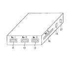
図2は、本発明の実施の形態1における回線選択装置の外観を示す斜視図である。図2に示すように、本実施の形態1では、回線選択装置2は、持ち運びが可能な大きさに形成されている。更に、回線選択装置2は、ポート11〜15と、電源ボタン27とを備えている。このうち、ポート11〜13は、USBポートであり、ポート14は、PCカードスロットである。ポート15は、回線選択装置2の装置設定の際に、設定用のコンピュータとの接続に利用される設定LANインタフェース26(図3参照)のポートである。
FIG. 2 is a perspective view showing an appearance of the line selection device according to
また、本実施の形態1では、ポート11〜13は、図3に示すネットワークインタフェース22〜24を構成する。そして、ポート11〜13それぞれには、各キャリアが提供する通信機器(図2において図示せず)が接続される。なお、ポート14にも、通信機器を接続することもでき、この場合は、ポート14もネットワークインタフェースを構成する。
Moreover, in this
図3は、本発明の実施の形態1における回線選択装置の構成を示すブロック図である。図3に示すように、回線選択装置2は、ネットワークインタフェース22〜24と、端末接続部16と、通信制御部17とを備えている。ネットワークインタフェース22〜24は、ネットワーク(インターネット4:図1参照)と端末装置1の接続に利用される。また、図3の例では、各ネットワークインタフェースには、番号(1)〜(3)が付与されている。
FIG. 3 is a block diagram showing the configuration of the line selection device according to
端末接続部16は、いずれかのネットワークインタフェースと端末装置1とを接続する。通信制御部17は、ネットワークインタフェース毎に通信速度を測定し、測定結果に基づいて、使用するネットワークインタフェースを決定する。そして、通信制御部17は、決定したネットワークインタフェースを動作させて、端末装置1とネットワークとを通信させる。
The
また、本実施の形態1では、ネットワークインタフェース22〜24は、図2に示したポート11〜13それぞれであり、各ポートには通信機器(図2および図3において図示せず)が接続されている。このため、本実施の形態1においては、通信制御部17は、ネットワークインタフェース21〜24の通信速度として、ポート11〜13(図2参照)に接続された通信機器の通信速度を測定する。なお、本実施の形態1は、この態様に限定されず、ネットワークインタフェースは、回線選択装置2に組み込まれた通信機器で構成されていても良い。
In the first embodiment, the network interfaces 22 to 24 are the ports 11 to 13 shown in FIG. 2, respectively, and a communication device (not shown in FIGS. 2 and 3) is connected to each port. Yes. For this reason, in this
このように、本実施の形態1においては、利用者の端末装置1には、通信用のデバイスおよびドライバソフトを追加する必要がなく、回線選択装置2を接続するだけで良い。また、回線選択装置2は、端末装置1とインターネットとの通信に最適な回線を選択する。よって、回線選択装置2を用いれば、利用者における面倒な差し替え作業の発生を抑制しつつ、端末装置1において動作が不安定になる事態の発生も抑制できる。
As described above, in the first embodiment, it is not necessary to add a communication device and driver software to the
また、本実施の形態1においては、回線選択装置2は、端末接続部16と、通信制御部17とに加えて、記憶部18と、ユーザ設定部211と、設定LAN−IP管理部212と、設定LAN制御部216と、統合制御部217と、電源管理部218とを備えている。
In the first embodiment, in addition to the
ユーザ設定部211は、設定LANインタフェース26を介して、ユーザからの設定を受け付け、設定された内容を、統合制御部217に入力する。統合制御部217は、設定された内容を、該当するモジュールへと反映させる。また、統合制御部217は、装置の核となる部分で、後述する、設定LAN制御部216、無線LAN制御部201、通信機器制御部208を制御する。さらに、統合制御部217は、電源管理部218から受け取った電源状態の変化に応じて、回線選択装置2の動作も制御する。
The
また、端末接続部16は、本実施の形態1では、無線通信(無線LAN)によって、ネットワークインタフェース22〜24と端末装置1とを接続する。このため、図3に示すように、端末接続部16は、無線LANインタフェース21と、無線LAN制御部201と、無線LAN−IP管理部202と、無線LAN認証情報管理部203と、アドレス変換部204と、アドレス変換テーブル205と、を備えている。
In the first embodiment, the
また、本実施の形態1では、無線LANインタフェース21は、ネットワークインタフェース22〜24と異なり、通信機能を備えている。無線LANインタフェース21は、無線LANカードなどの通信機器を用いることなく、それ自体によって回線を確立する。
In the first embodiment, the
更に、通信制御部17は、本実施の形態1では、回線情報収集部206と、通信機器制御部208とを備え、記憶部18に格納されている情報を用いて処理を行う。記憶部18は、ネットワークインタフェース22〜24として機能する各通信機器のドライバソフト213〜215と、通信機器接続情報テーブル209と、回線情報テーブル207とを格納している。
Further, in the first embodiment, the
また、上述した設定LAN−IP管理部212、および無線LAN−IP管理部202それぞれは、DHCPによって、予め設定されているIPアドレスを払い出す機能を備えている。
In addition, each of the setting LAN-
[各部の機能説明]
ここで、さらに図4を用いて、本実施の形態1における回線選択装置2の各部の機能について説明する。
[Functional description of each part]
Here, the function of each part of the
まず、利用者が、設定LANインタフェース26と設定用コンピュータ(図3において図示せず)とをLANケーブルで接続した後、回線選択装置2に対して設定を行うため、電源ボタン27を押圧する。これにより、回線選択装置2の電源がオンとなり、設定LAN−IP管理部212は、予め設定されているIPアドレスを払い出す。
First, after a user connects the setting
利用者は、設定用コンピュータを介して、設定LANインタフェース26のIPアドレスを指定して、設定LANインタフェース26に接続し、更に、接点LANインタフェース26を経由してユーザ設定部211に設定情報を入力する。
The user specifies the IP address of the setting
この場合、ユーザ設定部211は、設定用コンピュータの画面にGUIを表示させて設定情報を入力させても良い。また、ユーザ設定部211は、設定用コンピュータの画面にCLI(Command Line Interface)を表示させて設定情報を入力させても良い。但し、前者の場合は、回線選択装置2がWebサーバ機能を搭載している必要がある。また、前者の場合は、ユーザ設定部211は、httpまたはhttpsを用いて、ユーザにアクセスを行わせる。後者の場合は、ユーザ設定部211は、telnetまたはsshを用いてユーザにアクセスを行わせる。
In this case, the
また、利用者によって設定される設定項目は、無線LANについての設定であるLAN側と、通信機器についての設定であるWAN(Wide Area Network)側とに分けられる。図4は、本発明の実施の形態1における回線選択装置における設定項目の一例を示す図であり、図4(a)はLAN側の設定項目を示し、図4(b)はWAN側の設定項目を示す。 The setting items set by the user are divided into a LAN side that is a setting for a wireless LAN and a WAN (Wide Area Network) side that is a setting for a communication device. FIG. 4 is a diagram illustrating an example of setting items in the line selection device according to the first exemplary embodiment of the present invention. FIG. 4A illustrates setting items on the LAN side, and FIG. 4B illustrates setting items on the WAN side. Indicates an item.
図4(a)に示すように、LAN側の設定項目としては、利用される無線LANの規格、暗号化方式、認証情報(SSID、認証方式、認証ID、認証パスワード)、DHCP情報が挙げられる。また、認証情報は、無線LAN認証情報管理部203に登録され、DHCP情報は、無線LAN−IP管理部202に登録される。
As shown in FIG. 4A, the setting items on the LAN side include the standard of the wireless LAN to be used, the encryption method, authentication information (SSID, authentication method, authentication ID, authentication password), and DHCP information. . The authentication information is registered in the wireless LAN authentication
図4(b)に示すように、WAN側の設定項目としては、利用する回線毎の情報(アクセス先情報)、優先順位、後述する遅延時間の測定に用いるサーバ(測定用サイト5:図1参照)または端末のIPアドレスが挙げられる。アクセス先情報としては、利用するプロバイダまたはアクセスポイントのIDと、パスワードとが入力される。 As shown in FIG. 4B, the setting items on the WAN side include information (access destination information) for each line to be used, priority, and a server used for measurement of delay time described later (measurement site 5: FIG. 1). Or the IP address of the terminal. As the access destination information, an ID of a provider or access point to be used and a password are input.
また、後述する回線切替処理において、回線に設定された料金契約、即ち、従量制および定額制のいずれであるかが考慮されるため、アクセス先情報としては、回線に設定されている料金契約(従量制または定額制)も入力される。更に、後述する遅延時間(通信速度)の測定は若番のネットワークインタフェース(通信機器)から順に実行されるため、優先順位の高いネットワークインタフェースのアクセス先情報から順に登録される。また、WAN側の設定項目として入力された情報は、通信機器接続情報テーブル209に格納される。 In addition, in the line switching process to be described later, since the charge contract set for the line, that is, whether the pay-as-you-go system or the flat-rate system is considered, as the access destination information, the charge contract set for the line ( Pay-as-you-go or flat rate) is also entered. Furthermore, since the delay time (communication speed) measurement described later is executed in order from the youngest network interface (communication device), it is registered in order from the access destination information of the network interface having the highest priority. Information input as setting items on the WAN side is stored in the communication device connection information table 209.
続いて、LAN側の設定が完了すると、無線LAN制御部201は、無線LANインタフェース21を介して、Beaconパケットを定期的に送信する。これにより、端末装置1は、Beaconパケットを検知すると、回線選択装置2との間で接続処理を開始する。また、接続処理が開始されると、無線LAN認証情報管理部203は、認証処理を行う。認証処理が成功すると、無線LAN−IP管理部202は、予め設定されていたIPアドレスを払い出す。
Subsequently, when the setting on the LAN side is completed, the wireless
次に、WAN側の設定が完了すると、通信機器制御部208は、通信機器接続情報テーブル209に格納されている「優先順位」を参照して、使用するネットワークインタフェースを決定し、決定したネットワークインタフェースを用いて回線の接続を実行する。そして、接続先との間で認証が成功すると、対応するキャリアのアクセスポイント(31〜33)と回線選択装置2との間でコネクションが確立される(図1参照)。
Next, when the setting on the WAN side is completed, the communication
具体的には、本実施の形態1では、通信機器制御部208は、使用するネットワークインタフェースを決定すると、これに対応する通信機器のドライバソフトを記憶部18から読み込み、これを実行する。これにより、通信機器が動作し、対応する回線が接続される。また、このとき、必要なアプリケーションソフトがあれば、それも一緒に読み込まれて実行される。
Specifically, in the first embodiment, when the communication
また、LAN側では、無線LAN−IP管理部202が払い出したIPアドレスが使用され、WAN側では、プロバイダまたはAPから払いだされたIPアドレスが使用されている。よって、アドレス変換部204は、アドレス変換テーブル205を用いて、LAN側とWAN側との間を行き来するパケットのアドレス変換を実行する。アドレス変換テーブル205には、無線LAN制御部201および通信機器制御部208が、それぞれのアドレス情報を格納している。
On the LAN side, the IP address assigned by the wireless LAN-
また、LAN側とWAN側との設定が完了した後、回線情報収集部206は、WAN側の各ネットワークインタフェースを利用して、定期的に通信を行い、これによって回線の品質確認を実行する。
In addition, after the settings on the LAN side and the WAN side are completed, the line
そして、LAN側およびWAN側の設定が完了した後、ネットワークインタフェースによって回線が接続されている場合に、利用者が電源ボタン27を押すと、統合制御部217は、通信機器制御部208を介して回線を切断する。その後、電源管理部218は、電源をオフとする。また、この電源がオフの状態で、利用者が再び電源ボタン27を押すと、電源管理部218は電源をオンとし、統合制御部217は、通信機器制御部208に対して、優先するネットワークインタフェース、即ち、通信機器を使った接続を実行させる。
Then, after the settings on the LAN side and the WAN side are completed, when the line is connected by the network interface, when the user presses the
[装置動作]
次に、本発明の実施の形態1における回線選択装置2の動作について図5および図6を用いて説明する。以下の説明においては、適宜図1〜図4を参酌する。また、以下の説明では、利用者が、端末装置1を、無線LANインタフェース21を利用して、回線選択装置21に接続させ、更に、端末装置1を、ネットワークインタフェース22を利用してインターネット4に接続させているとする。
[Device operation]
Next, the operation of the
[接続候補決定処理]
最初に、図5を用いて、接続候補決定処理について説明する。図5は、本発明の実施の形態1における回線選択装置が接続候補を決定する際の動作を示すフロー図である。
[Connection candidate decision processing]
First, the connection candidate determination process will be described with reference to FIG. FIG. 5 is a flowchart showing an operation when the line selection device according to
まず、回線情報収集部206は、現在使用しているネットワークインタフェース以外で1番優先順位の高いネットワークインタフェースを選択する(ステップS1)。次に、回線情報収集部206は、選択したネットワークインタフェースの回線の料金設定が定額制であるかどうかを判定する(ステップS2)。
First, the line
ステップS2の判定の結果、定額制でない場合は、回線情報収集部206は、次のネットワークインタフェースを選択して(ステップS8)、再度ステップS2を実行する。一方、ステップS2の判定の結果、定額制である場合は、選択したネットワークインタフェースでの接続を実行する(ステップS3)。
If the result of determination in step S2 is that there is no flat rate system, the line
次に、接続の失敗が予め設定された回数以上生じているかどうかを判定する(ステップS4)。ステップS4の判定の結果、接続の失敗が設定された回数以上であった場合は、回線情報収集部206は、再度ステップS8を実行する。一方、ステップS4の判定の結果、接続の失敗が設定された回数以上でない場合は、回線情報収集部206は、ステップS5を実行する。
Next, it is determined whether or not connection failure has occurred more than a preset number of times (step S4). As a result of the determination in step S4, if the number of connection failures is equal to or greater than the set number, the line
ステップS5では、回線情報収集部206は、通信機器接続情報テーブル209にアクセスし、予め設定されたテストサイト(測定用サイト5:図1参照)の情報(遅延時間の測定に用いるサーバのIPアドレス)を取得する。そして、回線情報収集部206は、テストサイトにpingを送信し、遅延時間を測定する。なお、このとき測定された遅延時間は実質的に通信速度を表している。
In step S5, the line
なお、テストサイトが設定されていない場合は、回線情報収集部206は、ステップS1またはS8で選択された回線のデフォルトゲートウェイにpingを送信して、遅延時間を測定する。また、本実施の形態1では、回線情報収集部206は、例えば、遅延時間の測定を10回実行して、その平均値を算出し、算出した平均値を回線情報テーブル207に登録する。
If the test site is not set, the line
その後、回線情報収集部206は、全ての回線(従量制の回線を除く)について遅延時間の測定が行われているかどうかを判定する(ステップS6)。ステップS6の判定の結果、全ての回線について遅延時間の測定が行われている場合は、回線情報収集部206は、ステップS7を実行する。
Thereafter, the line
一方、ステップS6の判定の結果、全てのネットワークインタフェースについて遅延時間の測定が行われていない場合は、回線情報収集部206は、ステップS8を実行し、次のネットワークインタフェースについての遅延時間の測定を実行する。
On the other hand, as a result of the determination in step S6, if the delay time has not been measured for all the network interfaces, the line
ステップS7では、通信機器制御部208は、回線情報テーブル207に登録されている各ネットワークインタフェースの遅延時間を取得し、取得した遅延時間に基づいて、最も遅延時間の少ないネットワークインタフェースを特定する。そして、通信機器制御部208は、特定したネットワークインタフェースを接続候補に決定する。
In step S7, the communication
なお、全てのネットワークインタフェースについて遅延時間を測定しても、接続可能なネットワークインタフェースが存在せずに、接続候補を決定できない場合は、通信機器制御部208は、従量制の中で最も優先順位が高いネットワークインタフェースを接続候補として決定する。
Note that, even when the delay time is measured for all network interfaces, if there is no connectable network interface and connection candidates cannot be determined, the communication
ステップS7の実行後、接続候補決定処理は、一旦終了する。但し、本実施の形態では、ステップS1〜S8は、一定時間ごとに定期的に実行される。また、この定期的な実行の間隔は、利用者によって任意に設定されていても良いし、回線選択装置2によって設定されていても良い。
After execution of step S7, the connection candidate determination process is temporarily terminated. However, in the present embodiment, steps S1 to S8 are periodically executed at regular intervals. In addition, the periodic execution interval may be arbitrarily set by the user or may be set by the
[回線切替処理]
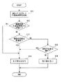
次に、図6を用いて、回線の切替処理について説明する。図6は、本発明の実施の形態1における回線選択装置が回線切替処理を実行する際の動作を示すフロー図である。
[Line switching processing]
Next, the line switching process will be described with reference to FIG. FIG. 6 is a flowchart showing an operation when the line selection apparatus according to
まず、回線情報収集部206は、現在使用しているネットワークインタフェースの回線の遅延時間を、他の回線と同様に、pingを送信して測定する(ステップS11)。なお、遅延時間は、通信が行われているときに測定されると、正確な値とならない可能性がある。よって、回線情報収集部206は、現在接続中の回線については、通信が行われていないタイミングで、ステップS11を実行する。
First, the line
次に、通信機器制御部208は、現在使用しているネットワークインタフェースの回線の遅延時間よりも、接続候補として決定された回線(図5のステップS7参照。)の遅延時間の方が短いかどうかを判定する(ステップS12)。
Next, the communication
ステップS12の判定の結果、接続候補として決定された回線(図5のステップS7参照。)の遅延時間の方が短い場合は、通信機器制御部208は、使用するネットワークインタフェースを、接続候補として決定されたネットワークインタフェースに切り替え(ステップS14)、その後、処理を終了する。一方、ステップS12の判定の結果、現在使用しているネットワークインタフェースの回線の遅延時間の方が短い場合は、現在使用しているネットワークインタフェースの回線が従量制であるかどうかを判定する(ステップS13)。
If the delay time of the line determined as a connection candidate as a result of the determination in step S12 (see step S7 in FIG. 5) is shorter, the communication
ステップS13の判定の結果、従量制である場合は、通信機器制御部208は、上述のステップS14を実行し、ネットワークインタフェースを、接続候補に切り替える。一方、ステップS13の判定の結果、現在接続中の回線が従量制でない場合は、通信機器制御部208は、現在使用しているネットワークインタフェースの回線が圏外となっているかどうかを判定する(ステップS15)。
If the result of determination in step S13 is metered, the communication
ステップS15の判定の結果、現在使用しているネットワークインタフェースの回線が圏外となっている場合は、通信機器制御部208は、上述のステップS14を実行し、ネットワークインタフェースを、接続候補に切り替える。一方、ステップS15の判定の結果、現在使用しているネットワークインタフェースの回線が圏外となっていない場合は、通信機器制御部208は、ネットワークインタフェースの切替を行わずに処理を終了する。
If the result of the determination in step S15 is that the network interface line currently in use is out of range, the communication
以上のように、本実施の形態1においては、現在接続している回線と接続候補の回線とが定期的に比較され、遅延時間の短い方が選択される。また、現在接続している回線の遅延時間が接続候補の回線の遅延時間よりも短い場合であっても、現在接続している回線が従量制である場合は、定額制の回線に切り替えられ、利用者の料金が過大にならないようにしている。 As described above, in the first embodiment, the currently connected line and the connection candidate line are periodically compared, and the one with the shorter delay time is selected. Also, even if the delay time of the currently connected line is shorter than the delay time of the connection candidate line, if the currently connected line is pay-as-you-go, it will be switched to a flat-rate line, The user's fee is not excessive.
更に、現在接続している回線の遅延時間が、接続候補の回線の遅延時間よりも短く、且つ現在接続している回線が定額制である場合は、現在接続中の回線が圏外になった場合にのみ切り替えが行われる。また、このため、現在接続中の回線が定額制で、候補が従量制の場合は現在接続中の回線が圏外になった場合にのみ切り替えが行われることになる。 Furthermore, if the delay time of the currently connected line is shorter than the delay time of the candidate connection line and the currently connected line is a flat rate system, the currently connected line is out of service area Switching is done only to. For this reason, when the currently connected line is a flat rate system and the candidate is a pay-per-use system, switching is performed only when the currently connected line is out of service area.
[実施の形態1の効果]
以上のように、本実施の形態1においては、通信機器の動作は、回線選択装置2によって行われ、また、通信機器のドライバソフトは回線選択装置2に搭載される。従って、回線選択装置2を用いれば、端末装置1に新たなデバイスおよびドライバソフトを追加することなく、モバイル環境下でのデータ通信を実現できる。
[Effect of Embodiment 1]
As described above, in the first embodiment, the operation of the communication device is performed by the
また、本実施の形態1では、回線選択装置2は、定期的に、使用されていないネットワークインタフェースによる通信を行って、各回線の状況を確認している。このため、回線選択装置2を用いれば、ある通信機器の使用中に電波状況が悪くなっても、自動的に別の通信機器の回線に切り替えられ、通信品質が確保される。
In the first embodiment, the
(実施の形態2)
次に、本発明の実施の形態2における回線選択装置3について、図7〜図9を参照しながら説明する。
(Embodiment 2)
Next, the
図7は、本発明の実施の形態2における回線選択装置の接続環境を示す図である。図7に示すように、本実施の形態2における回線選択装置3は、モバイル回線を提供する事業者(キャリア)のアクセスポイント31〜33に加えて、ホットスポットなどの公衆無線LANのアクセスポイント(AP)34および35にも接続できる。回線選択装置3は、この点で、実施の形態1における回線選択装置2と異なっている。なお、回線選択装置3も、実施の形態1における回線選択装置2と同様に、無線LAN(Local Area Network)インタフェースを搭載しており、無線LANによって、端末装置1に接続される。
FIG. 7 is a diagram showing a connection environment of the line selection device according to the second embodiment of the present invention. As shown in FIG. 7, the
図8は、本発明の実施の形態2における回線選択装置の構成を示すブロック図である。図8に示すように、回線選択装置3は、図3に示した回線選択装置2と異なり、ネットワークインタフェースとして、ネットワークインタフェース21〜24に加えて、ネットワークインタフェース25も備えている。
FIG. 8 is a block diagram showing the configuration of the line selection device according to
ネットワークインタフェース25は、公衆無線LANのアクセスポイント34または35(図7参照)との接続に用いられる。以降の説明では、ネットワークインタフェース25は、「無線LANインタフェース25」と表記する。無線LANインタフェース25は、無線LANインタフェース21と同様に、通信機能を備えており、それ自体によって回線を確立する。
The
また、図8に示すように、回線選択装置3においては、通信制御部19は、図2に示した通信制御部17と異なり、通信機器制御部208の代わりに、WAN側制御部219を備えている。また、記憶部20は、図2に示した記憶部18と異なり、通信機器接続情報テーブル209の代わりに、WAN側接続情報テーブル220を格納している。
Also, as shown in FIG. 8, in the
なお、これら以外については、回線選択装置3は、図2に示した回線選択装置2と同様に構成されている。よって、以下においては主に相違点を中心に説明する。
In other respects, the
本実施の形態2においても、利用者が、電源ボタン27を押した後、ユーザ設定部211を介して、LAN側とWAN側とについて設定が行われる。本実施の形態2では、図9(a)および(b)に示すように、LAN側の設定項目は、実施の形態1の場合(図4(a)参照)と同様であるが、WAN側の設定項目は、実施の形態1と異なっている。図9は、本発明の実施の形態2における回線選択装置における設定項目の一例を示す図であり、図9(a)はLAN側の設定項目を示し、図9(b)はWAN側の設定項目を示す。
Also in the second embodiment, after the user presses the
WAN側の設定項目は、回線選択装置3が、無線LANのアクセスポイント34および35にも接続可能であることから、図9(b)に示す通りとなる。具体的には、図9(b)に示すように、本実施の形態2においては、WAN側の設定項目としては、利用する接続先毎の情報(アクセス先情報)、公衆無線LANのアクセスポイント情報、優先順位、遅延時間の測定に用いるサーバまたは端末のIPアドレスが挙げられる。上記の公衆無線LANアクセスポイント情報には、SSID、認証方式、暗号化方式、認証情報、選択されているコース(従量制または定額制)が含まれる。
The setting items on the WAN side are as shown in FIG. 9B because the
また、図9(b)に示すように、本実施の形態2においては、優先順位は、ネットワークインタフェース22〜24に、無線LANインタフェース25も含めて設定される。但し、無線LANインタフェース25は、それ一つで複数のアクセスポイントにも接続できる。このため、無線LANインタフェース25については、アクセスポイント毎に優先順位が設定されている。
As shown in FIG. 9B, in the second embodiment, the priority order is set to the network interfaces 22 to 24 including the
また、本実施の形態2においては、WAN側の設定項目は、各アクセス先情報と、各公衆無線LANのアクセスポイント情報とのうち、優先順位の高いものから順に登録される。さらに、WAN側の設定項目として入力された情報は、WAN側接続情報テーブル220に格納される。 In the second embodiment, setting items on the WAN side are registered in descending order of priority among the access destination information and the access point information of each public wireless LAN. Further, information input as setting items on the WAN side is stored in the WAN side connection information table 220.
さらに、本実施の形態2では、WAN側制御部219は、WAN側の設定が完了すると、WAN側接続情報テーブル220に格納されている「優先順位」を参照して、使用するネットワークインタフェースを決定し、決定したネットワークインタフェースを用いて回線の接続を実行する。そして、接続先との間で認証が成功すると、対応するキャリアのアクセスポイント(31〜33)または無線LANのアクセスポイント(34、35)と回線選択装置3との間でコネクションが確立される(図7参照)。
Furthermore, in the second embodiment, when the WAN-side setting is completed, the WAN-
具体的には、本実施の形態2では、WAN側制御部219は、使用するネットワークインタフェースを決定すると、これに対応する通信機器のドライバソフトを記憶部18から読み込み、これを実行する。但し、使用するネットワークインタフェースが、無線LANインタフェース25である場合は、WAN側制御部219は、特にドライバソフトを読み込む必要はない。そして、いずれかの通信機器、または無線LANインタフェース25が動作し、対応する回線が接続される。
Specifically, in the second embodiment, when the WAN-
[装置動作]
続いて、本発明の実施の形態2における回線選択装置3の動作について説明する。但し、以下の説明は主に相違点のみについて行う。また、このため、適宜、実施の形態1で用いた図5および図6を参酌する。
[Device operation]
Next, the operation of the
まず、接続候補決定処理について説明する。本実施の形態2においては、回線選択装置3の回線情報収集部206およびWAN側制御部219によって、図5に示したステップS1〜S8が実行される。各ステップは、実施の形態1の場合と同様に行われる。
First, the connection candidate determination process will be described. In the second embodiment, steps S1 to S8 shown in FIG. 5 are executed by the line
但し、実施の形態1では、テストサイトが設定されていない場合、回線情報収集部206は、デフォルトゲートウェイにpingを送信して、遅延時間を測定していたが、本実施の形態2では、このような処理は実行しない。本実施の形態2においては、テストサイトの設定は必須である。
However, in the first embodiment, when a test site is not set, the line
これは、一般的に、無線LANの方が、それ以外の通信方式を採用する通信機器よりも、アクセスポイントまでの距離が短く、また回線速度も速いため、テストサイトの設定がない場合は、無線LANインタフェース25が接続候補として選択される可能性が極めて高いからである。
This is because the wireless LAN generally has a shorter distance to the access point and faster line speed than communication devices that employ other communication methods, so if there is no test site setting, This is because the possibility that the
また、本実施の形態2においても、接続候補を決定できない場合は、WAN側制御部219は、従量制の中で最も優先順位が高いネットワークインタフェースを接続候補として決定する。但し、このとき、本実施の形態2では、従量制で契約されている無線LANアクセスポイントも、無線LANアクセスポイント間の優先順位の順に接続候補の対象となる。
Also in the second embodiment, when the connection candidate cannot be determined, the WAN-
また、本実施の形態2においては、回線情報収集部206によって図6に示したステップS11が実行された後、WAN側制御部219によって図6に示したステップS12〜S16が実行される。本実施の形態2におけるステップS11〜S16では、接続候補として無線LANインタフェース25が用いられる可能性があるが、それ以外においては、実施の形態1と同様である。
Further, in the second embodiment, after step S11 shown in FIG. 6 is executed by the line
以上のように、本実施の形態2における回線選択装置3を用いれば、選択可能な回線として、無線LANも含めることができる。このため、利用者における利便性をいっそう向上させることが可能となる。また、本実施の形態2における回線選択装置3を用いた場合も、実施の形態1において述べた全ての効果を得ることができる。
As described above, when the
以上のように、本発明によれば、モバイル環境下において、利用者における面倒な通信機器の差し替え作業の発生を抑制できる。また、端末装置において動作が不安定になる事態の発生も抑制される。本発明は、コンピュータなどの端末装置を、モバイル環境下で利用する場合に有効である。 As described above, according to the present invention, it is possible to suppress the troublesome work of replacing a communication device by a user in a mobile environment. In addition, the occurrence of a situation where the operation becomes unstable in the terminal device is also suppressed. The present invention is effective when a terminal device such as a computer is used in a mobile environment.
1 端末装置
2 回路選択装置(実施の形態1)
3 回路選択装置(実施の形態2)
4 インターネット
5 測定用サイト
11〜15 ポート
16 端末接続部
17、19 通信制御部
18、20 記憶部
21、25 無線LANインタフェース
22〜24 ネットワークインタフェース
26 設定LANインタフェース
27 電源ボタン
31〜33 アクセスポイント(AP)
34、35 無線LANアクセスポイント(AP)
201 無線LAN制御部
202 無線LAN−IP管理部
203 無線LAN認証情報管理部
204 アドレス変換部
205 アドレス変換テーブル
206 回線情報収集部
207 回線情報テーブル
208 通信機器制御部
209 通信機器接続情報テーブル
211 ユーザ設定部
212 設定LAN−IP管理部
213〜215 ドライバソフト
216 設定LAN制御部
217 統合制御部
218 電源管理部
219 WAN側制御部
220 WAN側接続情報テーブル
1
3. Circuit selection device (Embodiment 2)
4
34, 35 Wireless LAN access point (AP)
DESCRIPTION OF
Claims (6)
前記ネットワークとの接続に利用される複数のネットワークインタフェースと、
いずれかの前記ネットワークインタフェースと前記端末装置とを接続する、端末接続部と、
前記複数のネットワークインタフェースそれぞれ毎に通信速度を測定し、測定結果に基づいて、使用するネットワークインタフェースを決定し、決定したネットワークインタフェースを動作させて、前記端末装置と前記ネットワークとを通信させる、通信制御部と、
を備えている、ことを特徴とする回線選択装置。 A device for selecting a line to be used for communication between a terminal device and a network,
A plurality of network interfaces used for connection to the network;
A terminal connection unit for connecting any one of the network interfaces and the terminal device;
Communication control for measuring a communication speed for each of the plurality of network interfaces, determining a network interface to be used based on the measurement result, and operating the determined network interface to communicate between the terminal device and the network. And
A line selection device comprising:
前記通信制御部は、使用するネットワークインタフェースを決定した後、前記記憶部から、決定したネットワークインタフェースを動作させるドライバソフトを読み込み、読み込んだドライバソフトを実行して、決定したネットワークインタフェースを動作させる、請求項1に記載の回線選択装置。 A storage unit for storing driver software for operating each of the plurality of network interfaces;
The communication control unit, after determining a network interface to be used, reads driver software for operating the determined network interface from the storage unit, and executes the read driver software to operate the determined network interface. Item 2. The line selection device according to item 1.
前記記憶部が、前記ポートで構成されたネットワークインタフェースのドライバソフトとして、前記通信機器のドライバソフトを格納し、
前記通信制御部が、
前記ポートで構成されたネットワークインタフェースの通信速度として、前記ポートに接続された通信機器の通信速度を測定し、
更に、前記通信機器のドライバソフトを実行して、前記通信機器を動作させることにより、前記ポートで構成されたネットワークインタフェースを動作させる、請求項2に記載の回線選択装置。 All or a part of the plurality of network interfaces is configured with a port that can be connected to an external communication device,
The storage unit stores driver software for the communication device as driver software for a network interface configured with the ports,
The communication control unit
As the communication speed of the network interface configured by the port, measure the communication speed of the communication device connected to the port,
The line selection device according to claim 2, further comprising: operating a network interface configured by the port by executing driver software of the communication device and operating the communication device.
Priority Applications (1)
| Application Number | Priority Date | Filing Date | Title |
|---|---|---|---|
| JP2011052823A JP2012191416A (en) | 2011-03-10 | 2011-03-10 | Line selection device |
Applications Claiming Priority (1)
| Application Number | Priority Date | Filing Date | Title |
|---|---|---|---|
| JP2011052823A JP2012191416A (en) | 2011-03-10 | 2011-03-10 | Line selection device |
Publications (1)
| Publication Number | Publication Date |
|---|---|
| JP2012191416A true JP2012191416A (en) | 2012-10-04 |
Family
ID=47084106
Family Applications (1)
| Application Number | Title | Priority Date | Filing Date |
|---|---|---|---|
| JP2011052823A Pending JP2012191416A (en) | 2011-03-10 | 2011-03-10 | Line selection device |
Country Status (1)
| Country | Link |
|---|---|
| JP (1) | JP2012191416A (en) |
Cited By (2)
| Publication number | Priority date | Publication date | Assignee | Title |
|---|---|---|---|---|
| JP2017199952A (en) * | 2016-04-25 | 2017-11-02 | Necプラットフォームズ株式会社 | Communication device, communication method, and program |
| JP2019087999A (en) * | 2017-11-06 | 2019-06-06 | Line株式会社 | Method and system for selecting optimal network path for media transmission in voip, and non-transitory computer readable recording medium |
Citations (7)
| Publication number | Priority date | Publication date | Assignee | Title |
|---|---|---|---|---|
| JPH10117199A (en) * | 1996-10-09 | 1998-05-06 | Oki Electric Ind Co Ltd | Route selection device |
| JP2001016276A (en) * | 1999-06-29 | 2001-01-19 | Canon Inc | Communication equipment, communication method, storage medium and communication system |
| JP2001228985A (en) * | 2000-02-16 | 2001-08-24 | Matsushita Graphic Communication Systems Inc | Image processor and print data receiving method |
| JP2002091709A (en) * | 2000-09-18 | 2002-03-29 | Toshiba Corp | Electronic equipment system, card type electronic component and communication method |
| JP2004104591A (en) * | 2002-09-11 | 2004-04-02 | Toshiba Corp | Method for displaying communication load and communication equipment |
| JP2005173641A (en) * | 2003-12-05 | 2005-06-30 | Ntt Communications Kk | Content delivery device, method, and program, and content display device |
| JP2007266834A (en) * | 2006-03-28 | 2007-10-11 | Sharp Corp | Communication system and method |
-
2011
- 2011-03-10 JP JP2011052823A patent/JP2012191416A/en active Pending
Patent Citations (7)
| Publication number | Priority date | Publication date | Assignee | Title |
|---|---|---|---|---|
| JPH10117199A (en) * | 1996-10-09 | 1998-05-06 | Oki Electric Ind Co Ltd | Route selection device |
| JP2001016276A (en) * | 1999-06-29 | 2001-01-19 | Canon Inc | Communication equipment, communication method, storage medium and communication system |
| JP2001228985A (en) * | 2000-02-16 | 2001-08-24 | Matsushita Graphic Communication Systems Inc | Image processor and print data receiving method |
| JP2002091709A (en) * | 2000-09-18 | 2002-03-29 | Toshiba Corp | Electronic equipment system, card type electronic component and communication method |
| JP2004104591A (en) * | 2002-09-11 | 2004-04-02 | Toshiba Corp | Method for displaying communication load and communication equipment |
| JP2005173641A (en) * | 2003-12-05 | 2005-06-30 | Ntt Communications Kk | Content delivery device, method, and program, and content display device |
| JP2007266834A (en) * | 2006-03-28 | 2007-10-11 | Sharp Corp | Communication system and method |
Cited By (3)
| Publication number | Priority date | Publication date | Assignee | Title |
|---|---|---|---|---|
| JP2017199952A (en) * | 2016-04-25 | 2017-11-02 | Necプラットフォームズ株式会社 | Communication device, communication method, and program |
| JP2019087999A (en) * | 2017-11-06 | 2019-06-06 | Line株式会社 | Method and system for selecting optimal network path for media transmission in voip, and non-transitory computer readable recording medium |
| JP7118860B2 (en) | 2017-11-06 | 2022-08-16 | Line株式会社 | Method and system for selecting optimal network path for media transmission in VoIP, non-transitory computer readable recording medium |
Similar Documents
| Publication | Publication Date | Title |
|---|---|---|
| EP2630756B1 (en) | Method and apparatus for sharing internet connection based on automatic configuration of network interface | |
| US9872202B2 (en) | Ad hoc wireless networking | |
| JP5278792B2 (en) | Network connection device, connection setting method, and connection setting program | |
| JP5277236B2 (en) | Portable network connection device | |
| US7016334B2 (en) | Device, system, method and computer readable medium for fast recovery of IP address change | |
| JP2017076994A (en) | Connection manager for wireless communication device | |
| CN105594257B (en) | Method and system for transmitting and receiving data | |
| WO2016165235A1 (en) | Wireless network connection method, device and terminal | |
| WO2014161478A1 (en) | Switching method for network interfaces, access device and computer storage medium | |
| US9219646B2 (en) | Managing actions of a network device | |
| JP2016519869A (en) | Multi-protocol driver to support IEEE 802.11 high-speed session transfer | |
| JP6345245B2 (en) | Network switching method and terminal device | |
| EP3291509A1 (en) | Information processing device and non-transitory recording medium | |
| JPWO2014132549A1 (en) | Portable information terminal, communication control method, and program | |
| EP2710855B1 (en) | Method and apparatus for considering routing information in the determination of an access network to be utilized | |
| US10657093B2 (en) | Managing actions of a network device based on policy settings corresponding to a removable wireless communication device | |
| US20160295301A1 (en) | Communication protocol control method and device in smart tv apparatus | |
| JP2010283413A (en) | Communication terminal and communication interface selection program therefor | |
| KR100972068B1 (en) | System and method for seamless for roaming between wireless networks | |
| WO2014044689A1 (en) | A method for connecting programs and/or applications to network interfaces | |
| JP2012191416A (en) | Line selection device | |
| JP2008187417A (en) | Cellular phone | |
| JP2004242058A (en) | System and method for wireless communication | |
| EP2670104B1 (en) | Method and device for transferring data via more than one communications interface | |
| JP2004253974A (en) | Communication means switching device |
Legal Events
| Date | Code | Title | Description |
|---|---|---|---|
| A621 | Written request for application examination |
Free format text: JAPANESE INTERMEDIATE CODE: A621 Effective date: 20140213 |
|
| A977 | Report on retrieval |
Free format text: JAPANESE INTERMEDIATE CODE: A971007 Effective date: 20141015 |
|
| A131 | Notification of reasons for refusal |
Free format text: JAPANESE INTERMEDIATE CODE: A131 Effective date: 20141021 |
|
| A521 | Written amendment |
Free format text: JAPANESE INTERMEDIATE CODE: A523 Effective date: 20141217 |
|
| RD01 | Notification of change of attorney |
Free format text: JAPANESE INTERMEDIATE CODE: A7421 Effective date: 20150123 |
|
| A02 | Decision of refusal |
Free format text: JAPANESE INTERMEDIATE CODE: A02 Effective date: 20150331 |