JP2012190870A - Housing device of electronic apparatus - Google Patents
Housing device of electronic apparatus Download PDFInfo
- Publication number
- JP2012190870A JP2012190870A JP2011050983A JP2011050983A JP2012190870A JP 2012190870 A JP2012190870 A JP 2012190870A JP 2011050983 A JP2011050983 A JP 2011050983A JP 2011050983 A JP2011050983 A JP 2011050983A JP 2012190870 A JP2012190870 A JP 2012190870A
- Authority
- JP
- Japan
- Prior art keywords
- cover
- opening
- case
- electronic component
- electronic device
- Prior art date
- Legal status (The legal status is an assumption and is not a legal conclusion. Google has not performed a legal analysis and makes no representation as to the accuracy of the status listed.)
- Granted
Links
Images


Landscapes
- Casings For Electric Apparatus (AREA)
Abstract
【課題】構造が簡素でケースの開口部に対して寸法的に大きな電子部品を実装したカバーを組み込むことができる電子機器の筐体装置を提供する。
【解決手段】開口部21の一辺部21aに凹溝または凸条からなる係止部22が形成され、内部に電子部品4が収容されるケース2と、一辺部3aに上記係止部に係合する凸条または凹溝からなる係合部33が形成され上記開口部を塞ぐカバー3を備え、上記カバーは、上記電子部品の少なくとも一部を保持すると共に、上記開口部に装着する際に上記係止部に上記係合部を係合させた状態で該係合部分の周りに回動され上記開口部を塞ぐようにした。
【選択図】図1To provide a casing device for an electronic device that has a simple structure and can incorporate a cover on which an electronic component having a large dimension is mounted in an opening of a case.
A locking part 22 made of a groove or a ridge is formed in one side part 21a of an opening part 21, and a case 2 in which an electronic component 4 is accommodated, and a side part 3a connected to the locking part. An engaging portion 33 made of a protruding ridge or groove is formed, and includes a cover 3 that closes the opening. The cover holds at least a part of the electronic component and is attached to the opening. In a state where the engaging portion is engaged with the locking portion, the engaging portion is rotated around the engaging portion to close the opening.
[Selection] Figure 1
Description
本発明は電子部品が収納された電子機器の筐体装置に関するものである。 The present invention relates to a casing device for an electronic device in which electronic components are stored.
電子部品が収納された電子機器を構成する従来の一般的な筐体装置として、電子部品を収納する表ケースと裏ケースとの間にゴムパッキンを配設させ、表ケースと裏ケースを接合させるように構成されたものがある(例えば、特許文献1参照)。 As a conventional general casing device constituting an electronic device in which electronic parts are stored, a rubber packing is disposed between the front case and the back case for storing electronic parts, and the front case and the back case are joined. (For example, refer patent document 1).
上記のような従来の電子機器の筐体装置においては、断面略コ字形の表ケースと裏ケースを接合させるので構造が複雑で、組立時に工数が増えるという課題があった。また、電子部品を実装した裏ケース(カバー)の寸法がケースの開口部の寸法より大きいものをスライドさせて組み込む場合には、組み付けが困難であるという課題があった。 The above-described conventional electronic apparatus casing device has a problem in that the structure is complicated because the front case and the back case having a substantially U-shaped cross section are joined, and man-hours increase during assembly. In addition, when the back case (cover) on which the electronic component is mounted has a size larger than the size of the opening of the case, it is difficult to assemble.
本発明は、上記のような従来技術の実状に鑑みてなされたもので、構造が簡素でケースの開口部に対して寸法的に大きな電子部品を実装したカバーを組み込むことができる電子機器の筐体装置を提供することを目的としている。 The present invention has been made in view of the actual situation of the prior art as described above, and has a simple structure and a housing for an electronic device in which a cover in which a large electronic component is mounted on a case opening can be incorporated. It aims to provide a body device.
本発明に係る電子機器の筐体装置は、開口部の一辺部に凹溝または凸条からなる係止部が形成され、内部に電子部品が収容されるケースと、一辺部に上記係止部に係合する凸条または凹溝からなる係合部が形成され上記開口部を塞ぐカバーを備え、上記カバーは、上記電子部品の少なくとも一部を保持すると共に、上記開口部に装着する際に上記係止部に上記係合部を係合させた状態で該係合部分の周りに回動され上記開口部を塞ぐようにしてなることを特徴とするものである。 An electronic device casing device according to the present invention includes a case in which an engaging part made of a groove or a ridge is formed on one side of the opening, and an electronic component is accommodated therein, and the engaging part on one side. And a cover for closing the opening. The cover holds at least a part of the electronic component and is attached to the opening. The engagement portion is engaged with the engagement portion and rotated around the engagement portion so as to close the opening.
本発明においては、電子部品を保持したカバーを開口部に装着する際に、ケースの係止部にカバーの係合部を係合させた状態で該係合部分の周りに回動して開口部を塞ぐようにしたので、構造が簡素で、開口部に対して電子部品を実装したカバーが寸法的に大きな場合でも効率的に組み込むことができる。 In the present invention, when the cover holding the electronic component is attached to the opening, the opening is rotated around the engaging portion with the engaging portion of the cover engaged with the engaging portion of the case. Since the portion is closed, the structure is simple, and even when the cover on which the electronic component is mounted in the opening is large in dimension, it can be efficiently incorporated.
実施の形態1.
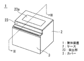
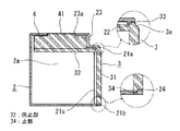
以下、本発明の実施の形態1に係る電子機器の筐体装置について図を参照して説明する。なお、図1は本発明の実施の形態1に係る電子機器の筐体装置を示す斜視図、図2は図1に示された筐体装置の分解斜視図であり、ケースと電子部品を保持したカバーの関係を示している。図3は図1のIII−III線を含む鉛直面における矢視断面図であり、要部構成のみ示している。図4は図1に示された電子機器の筐体装置の組立動作を説明する図である。
Hereinafter, a casing device for an electronic apparatus according to
図において、電子機器の筐体装置1は、有底四角筒状に形成された開口部21を有するケース2と、電子部品4が装着された開口部21を被装するカバー3とを組み合わせて構成される。ケース2における開口部21の一辺部21aには、図3に示すように凹溝からなる係止部22が形成されており、該係止部22は円弧状の曲面形状をなしている。また、ケース2は開口部21よりも奥行側における、一辺部21aに平行に連なる側壁部を該ケース2の外方に突出させた突出部23を有しており、該突出部23には窓23aが設けられている。
In the figure, a
カバー3はこの例では断面L字形に折曲された板状に形成されており、ケース2に対する被装時に蓋の機能を有する主面部31と、被装時にケース2の内部に入り込み、電子部品4を保持する機能を有する保持部32が形成されている。図3に示すように、該カバー3の一辺部3aを形成するL字状の角部の外角側には、上記係止部22に所定の角度範囲で回動可能に係合する凸条からなる係合部33が設けられ、該係合部33は回動が滑らかに行われるように円弧状の曲面形状をなしている。
In this example, the
ケース2の開口部21の両側部には、カバー3をケース2に被装させたときにカバー3の主面部31の裏面と当接する板状のケース当接部21cが設けられている。また、上記カバー3を構成する主面部31における上記一辺部3aに平行な対辺部3bには、凸部からなる止部34が離間された2箇所に設けられている。そして、上記ケース2の開口部21における上記一辺部21aに平行な対辺部21bには、上記止部34に係合する凹部からなる固定部24が2箇所に設けられており、カバー3の主面部31をケース当接部21cに当接させたときに上記止部34がケースの固定部24に係合されるように構成されている。
On both sides of the opening 21 of the
上記電子部品4の種類や収容数などは特に限定されるものではないが、この例では図2の上面部に表示部41を有し、収容時にケース2の窓23aから表示内容が視認できるように構成された表示モジュールが一体化された計量器を構成するデバイスが用いられている。また、電子部品4に接続される信号導体などは図示を省略しているが、一例としては保持部32及び主面部31を貫通して筐体装置1の外部に導出される。さらに、ケース2の内部空間2a部には、図示省略している他の電子部品類やケーブル類等が必要に応じてL字状のカバー3の内角側に実装されて収容される。この他、内部空間2aにおける保持部32の回動範囲に干渉しない位置にも部品類を設置することができる。
The type and number of
次に、上記の様に構成された実施の形態1の動作について、図4を参照して筐体装置1の組み立て順に沿って説明する。なお、電子部品4は予めカバー3の保持部32に図2のように実装されているものとする。
Next, the operation of the first embodiment configured as described above will be described according to the assembly order of the
(1)まず、カバー3を、その一辺部3aが最上部となるように主面部31を斜めに保持して、ケース2の開口部21方向に図2の矢印A方向にスライド移動させ、開口部21の凹溝からなる係止部22に対して、カバー3の凸条からなる係合部33を図4のように係合させる。
(2)次に、係止部22と係合部33の係合部分を支軸として、カバー3を図4の矢印Bの方向に回動させてケース2の開口部21を塞ぐようにケース2に装着する。
(3)次に、ケース2の固定部24に対して、カバー3の止部34を係合させる。
(1) First, the
(2) Next, the
(3) Next, the
このとき、凸部からなる止部34は、固定部24を有するケース2の対辺部21bを外側に弾性変形させて凹部からなる固定部24に嵌合される。この動作と同時に、カバー3の主面部31の両側部裏面がケース当接部21cに当接され、かつ、保持部32に取り付けられた電子部品4は、その表示部41がケース2の窓23aに入り込んだ図3に示す状態で収容されて組立が完了する。
At this time, the
上記のように構成された実施の形態1においては、有底四角筒状に形成されたケース2に対して電子部品4が装着された開口部21を被装するカバー3を回動させて嵌挿する構造にしたので、構造が簡素であると共に、開口部21の寸法L(図2に図示)に対して電子部品4を実装したカバー3が寸法的に大きな場合でも効率的に組み込むことができる。
また、ケース2の係止部22とカバー3の係合部33が円弧状の曲面形状であるので、回動がスムーズである。
In the first embodiment configured as described above, the
Moreover, since the
また、カバー3をケース2に被装させたときに、ケース当接部21cとカバー3の主面部31の両側部が当接されるので、容易に気密構造を構成することができる。また、ケース2の固定部24に対して、カバー3の止部34を係合させるようにしたことにより、カバー3がケース2に簡素な構造で保持される。さらに、自動組立機による組立も容易にできるほか、製品の分解、分離も容易である。
Further, when the
なお、上記実施の形態では、ケース2側の係止部22を凹溝によって構成し、カバー3側の係合部33を凸条によって構成したが、その逆に、係止部22を凸条に、係合部33を凹溝にしても良い。なお、図3の上側の拡大円に示すように、係止部22を構成する凹溝を円弧状に形成する場合、溝の最底部に対する該溝の頂部の高さを、内側よりも外側が低くなるように非対称にしても良い。その場合、係合部33を係止部22に係合しやすくできる。また、凹溝とその相手側の凸条を構成する曲面の角度を180度を若干超える程度に広げ、凸条が相手側の凹溝にスナップフィットによって入り込むように係合させても良い。その場合、カバー3を回動させるときの軸となる係合が確実となる。
In the above-described embodiment, the
また、ケース2の固定部24を凹部によって形成し、カバー3の止部34を凸部によって形成したが、その逆に、固定部24を凸部によって形成し、カバー3の止部34を凹部によって形成しても良い。さらに、例えばケース2の形状を変更し、密閉度を上げるために開口部21の周囲にパッキングを介装し、窓23aに透明板を設置し、あるいは窓23aを廃止するなど種々の変形や変更が可能であることは言うまでもない。
Further, the fixing
1 筐体装置、 2 ケース、 2a 内部空間、 21 開口部、 21a 一辺部、 21b 対辺部、 21c ケース当接部、 22 係止部、 23 突出部、 23a 窓、 24 固定部、 3 カバー、 3a 一辺部、 3b 対辺部、 31 主面部、 32 保持部、 33 係合部、 34 止部、 4 電子部品、 41 表示部。
DESCRIPTION OF
Claims (6)
Priority Applications (1)
| Application Number | Priority Date | Filing Date | Title |
|---|---|---|---|
| JP2011050983A JP5602664B2 (en) | 2011-03-09 | 2011-03-09 | Electronic equipment casing device |
Applications Claiming Priority (1)
| Application Number | Priority Date | Filing Date | Title |
|---|---|---|---|
| JP2011050983A JP5602664B2 (en) | 2011-03-09 | 2011-03-09 | Electronic equipment casing device |
Publications (3)
| Publication Number | Publication Date |
|---|---|
| JP2012190870A true JP2012190870A (en) | 2012-10-04 |
| JP2012190870A5 JP2012190870A5 (en) | 2013-08-22 |
| JP5602664B2 JP5602664B2 (en) | 2014-10-08 |
Family
ID=47083751
Family Applications (1)
| Application Number | Title | Priority Date | Filing Date |
|---|---|---|---|
| JP2011050983A Active JP5602664B2 (en) | 2011-03-09 | 2011-03-09 | Electronic equipment casing device |
Country Status (1)
| Country | Link |
|---|---|
| JP (1) | JP5602664B2 (en) |
Citations (3)
| Publication number | Priority date | Publication date | Assignee | Title |
|---|---|---|---|---|
| JPH0322378U (en) * | 1989-07-15 | 1991-03-07 | ||
| JPH0650388U (en) * | 1992-11-30 | 1994-07-08 | 日本電気三栄株式会社 | Support mechanism for case with revolving door |
| JP2007143622A (en) * | 2005-11-24 | 2007-06-14 | Seiko Instruments Inc | Transmitter for measuring heart rate and heart rate meter |
-
2011
- 2011-03-09 JP JP2011050983A patent/JP5602664B2/en active Active
Patent Citations (3)
| Publication number | Priority date | Publication date | Assignee | Title |
|---|---|---|---|---|
| JPH0322378U (en) * | 1989-07-15 | 1991-03-07 | ||
| JPH0650388U (en) * | 1992-11-30 | 1994-07-08 | 日本電気三栄株式会社 | Support mechanism for case with revolving door |
| JP2007143622A (en) * | 2005-11-24 | 2007-06-14 | Seiko Instruments Inc | Transmitter for measuring heart rate and heart rate meter |
Also Published As
| Publication number | Publication date |
|---|---|
| JP5602664B2 (en) | 2014-10-08 |
Similar Documents
| Publication | Publication Date | Title |
|---|---|---|
| JP5796952B2 (en) | Waterproof structure between connector and housing | |
| CN114071912B (en) | Resin structure | |
| JP5492693B2 (en) | Connector cover | |
| JP2012095460A (en) | Electrical connection box | |
| JPWO2019008933A1 (en) | Connector molded body, electronic control unit, and method for manufacturing connector molded body | |
| CN104466837B (en) | Electric circuit connection container | |
| JP2012013149A (en) | Packing structure | |
| JP5368202B2 (en) | Waterproof case | |
| JP5602664B2 (en) | Electronic equipment casing device | |
| JP5237022B2 (en) | Female connector, motor case, motor unit, and motor case manufacturing method | |
| JP2012033826A (en) | Housing | |
| JP5366336B2 (en) | Mobile device | |
| CN103369881A (en) | Electronic equipment | |
| JP4965243B2 (en) | Lock mechanism | |
| JP2009150283A (en) | Seal structure of synthetic resin parts | |
| CN107074155A (en) | The interim displacement structure of pair lid | |
| JP7469075B2 (en) | Resin Structure | |
| CN104515539B (en) | Detection device | |
| JP2013246914A (en) | Lever type connector | |
| JP2009134664A (en) | Wireless terminal device for automatic meter reading | |
| JP2012033827A (en) | Casing | |
| JP2008030737A (en) | Fitting structure of door weather strip | |
| JP4093755B2 (en) | Storage case for liquid crystal display elements | |
| JP2017524326A (en) | Junction box for solar cell module | |
| JP2543409Y2 (en) | Cover structure |
Legal Events
| Date | Code | Title | Description |
|---|---|---|---|
| A621 | Written request for application examination |
Free format text: JAPANESE INTERMEDIATE CODE: A621 Effective date: 20130530 |
|
| A521 | Request for written amendment filed |
Free format text: JAPANESE INTERMEDIATE CODE: A523 Effective date: 20130704 |
|
| A131 | Notification of reasons for refusal |
Free format text: JAPANESE INTERMEDIATE CODE: A131 Effective date: 20140121 |
|
| A977 | Report on retrieval |
Free format text: JAPANESE INTERMEDIATE CODE: A971007 Effective date: 20140123 |
|
| A521 | Request for written amendment filed |
Free format text: JAPANESE INTERMEDIATE CODE: A523 Effective date: 20140217 |
|
| TRDD | Decision of grant or rejection written | ||
| A01 | Written decision to grant a patent or to grant a registration (utility model) |
Free format text: JAPANESE INTERMEDIATE CODE: A01 Effective date: 20140723 |
|
| A61 | First payment of annual fees (during grant procedure) |
Free format text: JAPANESE INTERMEDIATE CODE: A61 Effective date: 20140820 |
|
| R150 | Certificate of patent or registration of utility model |
Ref document number: 5602664 Country of ref document: JP Free format text: JAPANESE INTERMEDIATE CODE: R150 |
|
| R250 | Receipt of annual fees |
Free format text: JAPANESE INTERMEDIATE CODE: R250 |
|
| R250 | Receipt of annual fees |
Free format text: JAPANESE INTERMEDIATE CODE: R250 |
|
| R250 | Receipt of annual fees |
Free format text: JAPANESE INTERMEDIATE CODE: R250 |
|
| R250 | Receipt of annual fees |
Free format text: JAPANESE INTERMEDIATE CODE: R250 |
|
| R250 | Receipt of annual fees |
Free format text: JAPANESE INTERMEDIATE CODE: R250 |
|
| R250 | Receipt of annual fees |
Free format text: JAPANESE INTERMEDIATE CODE: R250 |
|
| R250 | Receipt of annual fees |
Free format text: JAPANESE INTERMEDIATE CODE: R250 |
|
| R250 | Receipt of annual fees |
Free format text: JAPANESE INTERMEDIATE CODE: R250 |
|
| R250 | Receipt of annual fees |
Free format text: JAPANESE INTERMEDIATE CODE: R250 |