JP2012190796A - Turn signal switching device - Google Patents
Turn signal switching device Download PDFInfo
- Publication number
- JP2012190796A JP2012190796A JP2012038865A JP2012038865A JP2012190796A JP 2012190796 A JP2012190796 A JP 2012190796A JP 2012038865 A JP2012038865 A JP 2012038865A JP 2012038865 A JP2012038865 A JP 2012038865A JP 2012190796 A JP2012190796 A JP 2012190796A
- Authority
- JP
- Japan
- Prior art keywords
- cancel
- lever
- protrusion
- housing
- operation lever
- Prior art date
- Legal status (The legal status is an assumption and is not a legal conclusion. Google has not performed a legal analysis and makes no representation as to the accuracy of the status listed.)
- Granted
Links
Images


Classifications
-
- B—PERFORMING OPERATIONS; TRANSPORTING
- B60—VEHICLES IN GENERAL
- B60R—VEHICLES, VEHICLE FITTINGS, OR VEHICLE PARTS, NOT OTHERWISE PROVIDED FOR
- B60R16/00—Electric or fluid circuits specially adapted for vehicles and not otherwise provided for; Arrangement of elements of electric or fluid circuits specially adapted for vehicles and not otherwise provided for
- B60R16/02—Electric or fluid circuits specially adapted for vehicles and not otherwise provided for; Arrangement of elements of electric or fluid circuits specially adapted for vehicles and not otherwise provided for electric constitutive elements
-
- B—PERFORMING OPERATIONS; TRANSPORTING
- B60—VEHICLES IN GENERAL
- B60Q—ARRANGEMENT OF SIGNALLING OR LIGHTING DEVICES, THE MOUNTING OR SUPPORTING THEREOF OR CIRCUITS THEREFOR, FOR VEHICLES IN GENERAL
- B60Q1/00—Arrangement of optical signalling or lighting devices, the mounting or supporting thereof or circuits therefor
- B60Q1/26—Arrangement of optical signalling or lighting devices, the mounting or supporting thereof or circuits therefor the devices being primarily intended to indicate the vehicle, or parts thereof, or to give signals, to other traffic
- B60Q1/34—Arrangement of optical signalling or lighting devices, the mounting or supporting thereof or circuits therefor the devices being primarily intended to indicate the vehicle, or parts thereof, or to give signals, to other traffic for indicating change of drive direction
- B60Q1/40—Arrangement of optical signalling or lighting devices, the mounting or supporting thereof or circuits therefor the devices being primarily intended to indicate the vehicle, or parts thereof, or to give signals, to other traffic for indicating change of drive direction having mechanical, electric or electronic automatic return to inoperative position
- B60Q1/42—Arrangement of optical signalling or lighting devices, the mounting or supporting thereof or circuits therefor the devices being primarily intended to indicate the vehicle, or parts thereof, or to give signals, to other traffic for indicating change of drive direction having mechanical, electric or electronic automatic return to inoperative position having mechanical automatic return to inoperative position due to steering-wheel position, e.g. with roller wheel control
- B60Q1/425—Arrangement of optical signalling or lighting devices, the mounting or supporting thereof or circuits therefor the devices being primarily intended to indicate the vehicle, or parts thereof, or to give signals, to other traffic for indicating change of drive direction having mechanical, electric or electronic automatic return to inoperative position having mechanical automatic return to inoperative position due to steering-wheel position, e.g. with roller wheel control using a latching element for resetting a switching element
-
- H—ELECTRICITY
- H01—ELECTRIC ELEMENTS
- H01H—ELECTRIC SWITCHES; RELAYS; SELECTORS; EMERGENCY PROTECTIVE DEVICES
- H01H21/00—Switches operated by an operating part in the form of a pivotable member acted upon directly by a solid body, e.g. by a hand
- H01H21/02—Details
- H01H21/04—Cases; Covers
- H01H21/06—Cases; Covers interlocked with operating mechanism
-
- H—ELECTRICITY
- H01—ELECTRIC ELEMENTS
- H01H—ELECTRIC SWITCHES; RELAYS; SELECTORS; EMERGENCY PROTECTIVE DEVICES
- H01H25/00—Switches with compound movement of handle or other operating part
- H01H25/04—Operating part movable angularly in more than one plane, e.g. joystick
Abstract
Description
本発明は、中立位置から少なくとも左折指示位置と右折指示位置に回動可能な操作レバーを備えるターンシグナルスイッチ装置に関し、特にハンドルを一方向に回動させた後、逆方向に回動させた際に、操作レバーが左折指示位置または右折指示位置から中立位置に自動的に復帰する機能を備えたターンシグナルスイッチ装置に関する。 The present invention relates to a turn signal switch device including an operation lever that can be rotated from a neutral position to at least a left turn instruction position and a right turn instruction position, and in particular, when a handle is turned in one direction and then turned in a reverse direction. The present invention also relates to a turn signal switch device having a function of automatically returning an operation lever from a left turn instruction position or a right turn instruction position to a neutral position.
ターンシグナルスイッチ装置は、自動車の運転席に設けられるものであって、ステアリングコラムに取付けられたハウジングに、操作レバーを回動可能に設けてある。この操作レバーを中立位置から左折指示位置または右折指示位置に回動させることにより、左折または右折の指示ランプを点滅させることができるように、ハウジング内には操作レバーの回動に伴い駆動されるスイッチが設けられる。 The turn signal switch device is provided in a driver's seat of an automobile, and an operation lever is rotatably provided in a housing attached to a steering column. By rotating the operation lever from the neutral position to the left turn instruction position or the right turn instruction position, the left turn or right turn instruction lamp can be blinked so that the housing is driven as the operation lever rotates. A switch is provided.
操作レバーの回動方向を案内するため、ハウジング内にはカム面が設けられ、操作レバーの回動に伴い駆動される駆動体がカム面上を摺動する。また、操作レバーは、左折指示位置または右折指示位置においてラッチされるが、ハンドルを指示方向に回動させた後、逆方向に回動させることにより、左折指示位置または右折指示位置から中立位置に自動的に復帰させるキャンセル機構が、ターンシグナルスイッチ装置に設けられている。このようなキャンセル機構を備えたターンシグナルスイッチ装置としては、例えば特許文献1に挙げるようなものがある。 In order to guide the rotation direction of the operation lever, a cam surface is provided in the housing, and a driving body driven by the rotation of the operation lever slides on the cam surface. The operating lever is latched at the left turn instruction position or the right turn instruction position, but after turning the handle in the instruction direction and then in the reverse direction, the left turn instruction position or the right turn instruction position is changed to the neutral position. A cancel mechanism for automatically returning is provided in the turn signal switch device. As a turn signal switch device provided with such a cancellation mechanism, there is one as disclosed in Patent Document 1, for example.
ターンシグナルスイッチ装置のキャンセル機構には、ステアリングシャフトと共に回転するキャンセル突起の回転軌跡に進退動可能なレバー部材が設けられ、このレバー部材が操作レバーの回動やキャンセル突起の回動に連係して進退動及び回動し、操作レバーの自動復帰をなすように構成されている。従来のターンシグナルスイッチ装置においては、キャンセル突起と連係する第2操作レバー部材が、ハウジングに軸支された第1レバー部材に対して往復、回動可能に支持される構造を有していた。このため、部品点数が多く、低コスト化が困難であった。 The cancel mechanism of the turn signal switch device is provided with a lever member that can move forward and backward along the rotation locus of the cancel projection that rotates together with the steering shaft, and this lever member is linked to the rotation of the operation lever and the cancel projection. The control lever is configured to move forward and backward and rotate to automatically return the operation lever. The conventional turn signal switch device has a structure in which the second operation lever member linked to the cancel protrusion is supported so as to be able to reciprocate and rotate with respect to the first lever member pivotally supported by the housing. For this reason, the number of parts is large, and cost reduction is difficult.
また、キャンセル機構においてはレバー部材をキャンセル突起側に弾性付勢しておく必要があるが、従来のターンシグナルスイッチ装置では、弾性付勢部材として捻りコイルばねを設けており、この捻りコイルばねをハウジング内の周縁部からレバー部材に向かって延びるように配置していた。このため、ハウジング内に捻りコイルばねのためのスペースが必要となり、ハウジングの小型化を阻害していた。 Further, in the cancel mechanism, it is necessary to elastically bias the lever member toward the cancel protrusion, but in the conventional turn signal switch device, a torsion coil spring is provided as an elastic bias member, and this torsion coil spring is It arrange | positions so that it may extend toward the lever member from the peripheral part in a housing. For this reason, a space for a torsion coil spring is required in the housing, which hinders downsizing of the housing.
本発明は前記課題を鑑みてなされたものであり、部品点数が少なく簡易な構造でキャンセル機構を構成できると共にハウジングの小型化も図ることのできるターンシグナルスイッチ装置を提供することを目的とする。 The present invention has been made in view of the above-described problems, and an object of the present invention is to provide a turn signal switch device that can form a cancel mechanism with a simple structure with a small number of parts and that can be downsized.
前記課題を解決するため、本発明の請求項1に係るターンシグナルスイッチ装置は、操作レバーと、該操作レバーの基部を一平面上で回動可能に支持する保持体と、該保持体を前記一平面と交差する他平面上で回動可能に支持するハウジングと、該ハウジング内に設けられて、ステアリングシャフトに設けたキャンセル突起の回転軌跡への進退動及び回動が可能なキャンセルレバーとを備え、
前記ハウジング内に、前記操作レバーの基部と対向するようにカム部材が設けられ、前記操作レバーの基部には、前記カム部材に弾接されるように、第1弾性部材を介して第1駆動体が取付けられ、
前記カム部材は、前記操作レバーが中立位置にあるときに前記第1駆動体を係止する中央部と、前記操作レバーが少なくとも左折指示位置及び右折指示位置のいずれかの位置にあるときに、前記第1駆動体を係止するラッチ用突起と、前記中央部及び前記ラッチ用突起が形成されている位置以外において、前記中央部へ向けて前記第1駆動体を弾性付勢するように形成された傾斜面とを有し、
前記キャンセルレバーは、圧縮状態にあるキャンセル用弾性部材を介して前記ハウジング内に設けられ、かつ、前記回転軌跡側に第1頂部を有する面が形成された係合突起を備え、
前記保持体は、前記操作レバーが前記中立位置にあるとき、前記係合突起と当接する第2頂部を有する面が形成された係合部を備え、
前記操作レバーが前記中立位置にあるとき、前記係合突起及び前記係合部は、第1頂部及び第2頂部同士が当接され、前記キャンセルレバーは、前記回転軌跡外に退出されていることを特徴として構成されている。
In order to solve the above-described problem, a turn signal switch device according to claim 1 of the present invention includes an operation lever, a holding body that rotatably supports a base portion of the operation lever on a single plane, and the holding body. A housing that is rotatably supported on another plane that intersects with one plane, and a cancel lever that is provided in the housing and is capable of advancing, retracting, and rotating to a rotation locus of a cancel projection provided on the steering shaft. Prepared,
A cam member is provided in the housing so as to face the base of the operation lever, and the base of the operation lever is first driven through a first elastic member so as to be elastically contacted with the cam member. The body is installed and
The cam member, when the operation lever is in a neutral position, the central portion that locks the first drive body, and when the operation lever is at least one of a left turn instruction position and a right turn instruction position, Formed so as to elastically bias the first driving body toward the central portion other than the position of the latching projection for locking the first driving body and the central portion and the latching projection. An inclined surface,
The cancel lever is provided in the housing via a canceling elastic member in a compressed state, and includes an engaging protrusion having a surface having a first top on the rotation locus side,
The holding body includes an engaging portion formed with a surface having a second top portion that comes into contact with the engaging protrusion when the operation lever is in the neutral position.
When the operation lever is in the neutral position, the engaging protrusion and the engaging portion are in contact with each other between the first top portion and the second top portion, and the cancel lever is retracted out of the rotation locus. It is configured as a feature.
また、本発明の請求項2に係るターンシグナルスイッチ装置は、前記キャンセルレバーは、前記回転軌跡に向けて突出されて該回転軌跡に進退動する突出部と、該突出部の突出方向とは反対方向に突出される2つの腕部と、それら2つの腕部の間に形成される凹部と、前記ハウジングの内面に向けて突出する下突部とを有し、前記ハウジングには、前記下突部を前記回動軌跡に対して往復動可能に案内する案内長孔が形成され、前記保持体には、前記キャンセルレバーの前記凹部の内側面に弾接されるように、第2弾性部材を介して第2駆動体が取付けられることを特徴として構成されている。
Further, in the turn signal switch device according to
さらに、本発明の請求項3に係るターンシグナルスイッチ装置は、前記保持体は、前記回転軌跡に向けて突出される突出面部と、該突出面部に形成されて、前記第2駆動体を往復動可能に案内する挿通孔部とを有し、前記第2駆動体は、前記挿通孔部を挿通して前記凹部内に延設され、該凹部の内側面に押し当てられる被押圧部を有することを特徴として構成されている。
Further, in the turn signal switch device according to
さらにまた、本発明の請求項4に係るターンシグナルスイッチ装置は、前記カム部材は、前記突出面部の一側に配置され、前記キャンセルレバーは、前記突出面部の他側に配置され、前記係合部は、前記挿通孔部よりも前記回転軌跡側に位置するように、前記突出面部に形成されることを特徴として構成されている。
Furthermore, in the turn signal switch device according to
そして、本発明の請求項5に係るターンシグナルスイッチ装置は、前記キャンセルレバーは、前記2つの腕部が突出される方向と同じ方向に突出される保持部を有し、前記ハウジングは、前記保持部と対向するキャンセルレバー保持部を有し、前記キャンセル用弾性部材は、該キャンセル用弾性部材の一端が前記保持部に保持され、他端が前記キャンセルレバー保持部に保持されることを特徴として構成されている。
In the turn signal switch device according to
また、本発明の請求項6に係るターンシグナルスイッチ装置は、前記ハウジング及び前記キャンセルレバーの少なくとも一方は、前記他平面と交差する方向への前記キャンセルレバーの振動を抑制する振動抑制手段を有することを特徴として構成されている。
Further, in the turn signal switch device according to
さらに、本発明の請求項7に係るターンシグナルスイッチ装置は、前記ハウジング及び前記キャンセルレバーの互いの対向面の少なくとも一方は、吸音部材を有することを特徴として構成されている。 Furthermore, the turn signal switch device according to claim 7 of the present invention is characterized in that at least one of the opposing surfaces of the housing and the cancel lever has a sound absorbing member.
本発明の請求項1に係るターンシグナルスイッチ装置によれば、キャンセルレバーがキャンセル突起の回転軌跡への進退動及び回動が可能となるように、圧縮状態にあるキャンセル用弾性部材を介してキャンセルレバーをハウジングに設ける構成としたため、キャンセル用弾性部材及びキャンセルレバーをそれぞれひとつの部材で構成できるので、部品点数が少なく簡易な構造でキャンセル機構を構成できる。また、それら各部材を小さなスペースに配置させることができるので、ターンシグナルスイッチ装置の小型化を図ることができる。さらに、第1駆動体がカム部材に弾接されるように、第1弾性部材を介して第1駆動体を操作レバーの基部に取付けたため、操作レバーに対応する弾性部材とキャンセル機構に対応する弾性部材とを別々に構成できるので、設計の自由度を向上でき、フィーリングに優れたターンシグナルスイッチ装置を実現することができる。 According to the turn signal switch device of the first aspect of the present invention, the cancel lever is canceled via the cancel elastic member in the compressed state so that the cancel lever can advance and retreat to the rotation locus and turn. Since the lever is provided in the housing, each of the canceling elastic member and the canceling lever can be formed of one member, so that the canceling mechanism can be configured with a simple structure with a small number of parts. Moreover, since these members can be arranged in a small space, the turn signal switch device can be miniaturized. Further, since the first drive body is attached to the base of the operation lever via the first elastic member so that the first drive body is elastically contacted with the cam member, the elastic member corresponding to the operation lever and the cancel mechanism are supported. Since the elastic member can be configured separately, the degree of freedom in design can be improved, and a turn signal switch device excellent in feeling can be realized.
また、本発明の請求項2に係るターンシグナルスイッチ装置によれば、右折又は左折指示位置にラッチされた操作レバーがたとえロックされても、右折又は左折後にハンドルを元の状態に戻すと、中立位置に操作レバーを確実に自動復帰させることができる。
Further, according to the turn signal switch device according to
さらに、本発明の請求項3に係るターンシグナルスイッチ装置によれば、ラッチされた操作レバーがたとえロックされても、簡単な構成で確実に操作レバーを自動復帰させる構成を実現できる。 Furthermore, according to the turn signal switch device of the third aspect of the present invention, it is possible to realize a configuration in which the operation lever is automatically returned with a simple configuration even if the latched operation lever is locked.
また、請求項4に係るターンシグナルスイッチ装置によれば、突出面部の上下のスペースにカム部材及びキャンセルレバーをそれぞれ配置でき、スペースを有効に利用できるので、ターンシグナルスイッチ装置のさらなる小型化を図ることができる。 According to the turn signal switch device of the fourth aspect, the cam member and the cancel lever can be respectively disposed in the space above and below the projecting surface portion, and the space can be used effectively. Therefore, the turn signal switch device can be further downsized. be able to.
さらに、請求項5に係るターンシグナルスイッチ装置によれば、キャンセルレバーがキャンセル突起の回転軌跡への進退動及び回動をより簡単な構成で確実に行うことができるので、ターンシグナルスイッチ装置の信頼性を向上でき、かつ、さらなる小型化を図ることができる。 Furthermore, according to the turn signal switch device of the fifth aspect, since the cancel lever can reliably advance and retreat and rotate the cancel protrusion with respect to the rotation trajectory with a simpler structure, the turn signal switch device is reliable. Performance can be improved, and further downsizing can be achieved.
さらにまた、請求項6に係るターンシグナルスイッチ装置によれば、自動車の振動が加わってもキャンセルレバーの動きが抑制されるので、異音が発生するのを防止できる。 Furthermore, according to the turn signal switch device of the sixth aspect, since the movement of the cancel lever is suppressed even when the vibration of the automobile is applied, it is possible to prevent the generation of abnormal noise.
また、請求項7に係るターンシグナルスイッチ装置によれば、自動車の振動でキャンセルレバーが加振されても、異音が発生するのを防止できる。 According to the turn signal switch device of the seventh aspect, even if the cancel lever is vibrated by the vibration of the automobile, it is possible to prevent the generation of abnormal noise.
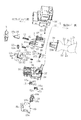
本発明の実施形態について図面に沿って詳細に説明する。図1は本実施形態におけるターンシグナルスイッチ装置の分解斜視図である。ターンシグナルスイッチ装置は、自動車のステアリングコラム内に取付けられるハウジング2と、ハウジング2から外方に突出されるように設けられて車内に露出する操作レバー1とを有している。
Embodiments of the present invention will be described in detail with reference to the drawings. FIG. 1 is an exploded perspective view of a turn signal switch device according to the present embodiment. The turn signal switch device includes a
操作レバー1は、図1中A1〜A4方向の4方向に回動操作可能である。A1方向とA2方向は、一平面、すなわち、平面P1(後述する案内凸部44の軸線と直交する平面)と平行な同一面内にあり、A3方向とA4方向は、平面P1と交差する他平面、すなわち、平面P2(後述するシャフト22の軸線と直交する平面)と平行な同一面内にある。操作レバー1をA1方向またはA2方向に回動させると、左折指示位置または右折指示位置において操作レバー1がラッチされ、ターンシグナルスイッチ装置からは左折指示または右折指示の出力がなされる。
The operation lever 1 can be rotated in four directions A1 to A4 in FIG. The A1 direction and the A2 direction are in the same plane parallel to one plane, that is, the plane P1 (a plane orthogonal to the axis of the
ターンシグナルスイッチ装置は、自動車のステアリングコラムに取付けられる。ステアリングシャフト(図示略)は操作レバー1が突出する側と反対側に配置され、ターンシグナルスイッチ装置を構成するキャンセルレバー4が、操作レバー1の操作及びハンドル操作に伴って、ステアリングシャフトと連動する。
The turn signal switch device is attached to a steering column of an automobile. A steering shaft (not shown) is arranged on the side opposite to the side from which the operation lever 1 protrudes, and the cancel
操作レバー1のA3方向及びA4方向への回動操作については、操作方向に応じて任意の機能を割り当てることができる。例えば、A4方向の回動操作についてはラッチ可能としてヘッドライトをハイビームに切替える機能を持たせ、A3方向の回動操作についてはラッチせず自動復帰するようにして、操作中のみヘッドライトを点灯する機能を持たせることができる。 For the rotation operation of the operation lever 1 in the A3 direction and the A4 direction, an arbitrary function can be assigned according to the operation direction. For example, the function of switching the headlight to a high beam is provided so that it can be latched for the turning operation in the A4 direction, and the headlight is turned on only during the operation so that the turning operation in the A3 direction is automatically returned without being latched. Can have a function.
図1において、操作レバー1は、根元側を構成してハウジング2内に納められる基部20と、車内に露出して運転者に操作される操作部21とを有している。
In FIG. 1, the operation lever 1 has a
ハウジング2は、上ケース30と下ケース33とを一体化して構成され、内部には空間が形成される。ハウジング2内の空間に、操作レバー1の基部20及び各種部品が納められる。ハウジング2内に納められる主な部品は、保持体3、キャンセルレバー4、カム部材5、第1駆動体10、第2駆動体12及び揺動レバー15である。
The
保持体3は、操作レバー1の基部20を挿入でき、かつ、基部20がカム部材5側において露出されるように形成された箱状の本体部40を有する。本体部40は、ステアリングシャフト側に突出する突出面部41と、本体部40の上面から突出する案内凸部44とを有する。案内凸部44はハウジング2に回動可能に支持される。ここで保持体3は、案内凸部44を中心に回動可能にハウジング2に支持されているので、操作レバー1がA1方向又はA2方向に回動操作されると、保持体3の突出面部41がB1方向又はB2方向に回動する。基部20は、基部20に形成される軸挿通部20bと保持体3に形成される軸挿通部48とに挿通されたシャフト22を中心にして、保持体3に回動可能に支持される。したがって、操作レバー1をA3方向又はA4方向に回動操作すると、保持体3は回動せず、操作レバー1のみが回動する。
The holding
保持体3の突出面部41の先端部の下面側に係合面部42が形成されており、これがキャンセルレバー4に設けた係合突起53と係脱する。その詳細については後述する。なお、突出面部41には、第2駆動体12を往復動可能に案内する、第2駆動体挿通孔41a(挿通孔部)が形成される(図2)。また、図1に示すように、突出面部41の下面には、後述する第2スライダー17の長孔部17aに挿入される挿入ピン43が形成されている。
An
第1駆動体10は、第1弾性部材11を介して基部20の収納凹部20aに摺動可能に取付けられ、基部20と対向して配置されるカム部材5に先端部10aが押し付けられるように弾性付勢されている。第1駆動体10は、先端部10aがカム部材5に案内され、操作レバー1の回動操作に伴い4方向に摺動する。すなわち、カム部材5の基部20と対向するカム面部60には、操作レバー1の操作方向に対応した十字状のカム溝(図示略)が形成されている。このカム溝は、操作レバー1の中立位置に対応する中央部60aが最も凹んでいて、中央部60aから周辺方向に向かって上る傾斜面60bとなっている。なお、一部の傾斜面60bには、後述するラッチ用突起61(図2)が形成されている。第1駆動体10は、カム溝に対して弾性的に押し付けられているので、操作レバー1が4方向のいずれかに回動操作されて先端部10aが傾斜面60b上にあるとき、第1弾性部材11の弾性付勢力によって、操作レバー1は中立位置に自動復帰する方向に弾性付勢されることとなる。
The
図2に示すように、第2駆動体12は、第2弾性部材13を介して保持体3に取付けられ、ステアリングシャフト側に向かって弾性付勢されている。ここで第2弾性部材13の一端は、第2駆動体12の突起保持部12bに保持され、他端は保持体3の第2弾性部材保持部46に保持されている。第2駆動体12は、下方に突出する被押圧部12aを有し、被押圧部12aが保持体3の突出面部41に形成された第2駆動体挿通孔41aに挿通される。後述するキャンセル動作は、被押圧部12aがキャンセルレバー4と連動して行われる。
As shown in FIG. 2, the
キャンセルレバー4は、ステアリングシャフトに設けられたキャンセル突起6a(図3)の回動軌跡に向けて突出された突出部50と、操作レバー1側に突出するように形成された第1腕部51及び第2腕部52とを有している。第1腕部51と第2腕部52との間に凹部4aが形成されている。第1腕部51において、第2腕部52と対向する第1押圧面部51aは、操作レバー1が左折指示方向(A1方向)に回動操作された後にキャンセル動作が行われる際に、被押圧部12aを押圧する。第1腕部51において、突出部50が突出する方向と反対側の第2押圧面部51bは、操作レバー1が左折指示方向(A1方向)に回動操作されラッチされた後にロックされた状態でキャンセル動作が行われる際に、被押圧部12aを押圧する。第2腕部52は、右折指示時において同様の機能を有する第1押圧面部52a及び第2押圧面部52bを有する。以上の構成によって、後述するように、右折又は左折指示位置にラッチされた操作レバー1がたとえロックされても、右折又は左折後にハンドルの元の状態に戻すと、中立位置に操作レバー1を確実に自動復帰させることができる。
The cancel
また、キャンセルレバー4の上面には、凹部4a側の縁部における第1腕部51と第2腕部52の中間位置に係合突起53が立設され形成されている。図2に示すように、キャンセルレバー4は、キャンセル用弾性部材(第3弾性部材14)を介して下ケース33の第3弾性部材保持部36(キャンセルレバー保持部)に取り付けられており、その下面に下突部54が突出するように形成されている。
Further, on the upper surface of the cancel
ハウジング2の下ケース33には、キャンセルレバー4の下突部54を、ステアリングシャフト側、すなわち、キャンセル突起6aの回動軌跡側へ向けて進退動可能に案内する案内長孔35が形成されている。したがって、キャンセルレバー4は、下突部54が案内長孔35によってC3方向またはC4方向に進退動可能に案内されると共に、案内長孔35における任意の位置で図1中のC1方向またはC2方向に回動可能である。
The
キャンセルレバー4は、ハウジング2に取付けられる、例えばコイルばねからなる第3弾性部材14(キャンセル用弾性部材)により、ステアリングシャフトに向けて常時弾性付勢されている。すなわち第3弾性部材14は、図2に示すように、後述する保持部55と、下ケース33の第3弾性部材保持部36との間に常時圧縮状態で支持される。
The cancel
図2に示すように、ハウジング2を構成する下ケース33には、揺動レバー15から下方に延設された連係部15bを挿通させるための開口部34や、保持体3を回動方向に支持する案内凸部37が形成されている。揺動レバー15は、支軸部15aが操作レバー1の基部20に揺動可能に支持される。したがって、操作レバー1が図1中のA3方向またはA4方向に回動操作されると、揺動レバー15はD1方向またはD2方向に揺動する。
As shown in FIG. 2, the
連係部15bは、下ケース33の開口部34の下方に配置される揺動部材18に係合して揺動部材18を揺動させる。揺動部材18は、回動中心部18aが下ケース33に揺動可能に支持され、円弧形状の被係合部18cが連結部15bに係合する。被係合部18cの、回動中心部18aに対して反対側の端部に形成される突部18bは、第1スライダー16に形成された長孔部16a挿入される。したがって第1スライダー16は、揺動レバー15の揺動に伴って回動する揺動部材18によって、図1中のE1方向とE2方向に沿ってスライド移動することができる。
The
基板19には、第1接点部19aと第2接点部19bとが配置される。第1スライダー16は、第1接点部19aに対して接触する接点(図示しない)を有する。揺動レバー15のD1方向またはD2方向の揺動に伴いE1方向またはE2方向に沿って第1スライダー16をスライド移動することにより、第1スライダー16の接点と第1接点部19aとの接触状態を切り替えることができる。
A
ハウジング2には、保持体3の回動に伴いスライドする第2スライダー17が設けられる。保持体3の下面に形成された連係ピン43は、第2スライダー17に形成される長孔部17aに挿通される。したがって、保持体3がB1方向またはB2方向に回動することで、第2スライダー17は図1中のF2方向またはF1方向にスライド移動する。
The
第2スライダー17には、第2接点部19bに対して接触する接点(図示しない)が設けられており、F1方向またはF2方向にスライド移動することにより、第2接点部19bとの接触状態を切り替えることができる。
The
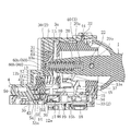
図2は、ターンシグナルスイッチ装置の縦断面図である。操作レバー1の基部20のステアリングシャフト側(図中左側)には、第1弾性部材11を介して第1駆動体10が支持されている。操作レバー1の基部20の先端部及び第1駆動体10の先端部10aは、図2に示すように、保持体3の開口部3aからカム部材5に向けて突出している。そして、第1駆動体10の先端部10aは、カム部材5のカム面部60に当接している。
FIG. 2 is a longitudinal sectional view of the turn signal switch device. A
カム面部60は、前述の通り、中央部60aから4方向に延びるカム溝が形成されており、操作レバー1をラッチするためのラッチ用突起61がカム溝上の所望の位置に形成されている。ラッチ用突起61は、例えば、ヘッドライトをハイビームに切替えたり、左折指示または右折指示する際に操作レバー1をラッチするように形成される。図2は、操作レバー1が中立位置にある状態を表しており、第1駆動体10の先端部10aはカム面部60の中央部に位置している。
As described above, the
操作レバー1を図2の状態から図1のA1方向またはA2方向に回動操作すると、第1駆動体10の先端部10aは、図2の紙面と垂直な方向に移動して、カム面部60の傾斜面60bを登る。操作レバー1が左折指示位置または右折指示位置まで回動されると、第1駆動体10の先端部10aはラッチ用突起61に係合して、操作レバー1がラッチされた状態となる。
When the operation lever 1 is rotated from the state shown in FIG. 2 in the direction A1 or A2 in FIG. 1, the
ラッチされた操作レバー1に対し中立位置に自動復帰させる方向に力がかかると、第1駆動体10の先端部10aがラッチ用突起61を乗り越えてカム溝の中央部60a側の傾斜面60bに移動する。そして、第1駆動体10の先端部10aは、第1弾性部材11の弾性付勢力によりカム面部60の傾斜面60bを下って中央部60aに戻り、操作レバー1は、ラッチ状態が解除されて中立位置に復帰する。
When a force is applied to the latched operation lever 1 in a direction to automatically return to the neutral position, the
ハウジング2を構成する上ケース30には、内面に収納部31が形成され、カム部材5が納められている。また、上ケース30の内面には、保持体3の案内凸部44を嵌入する凹状の案内凹部32が形成され、下ケース33の内面には、保持体3の下面に形成された案内凹部45に嵌入される案内凸部37が形成されている。したがって、保持体3は、図1中B1またはB2方向に回動可能にハウジングに支持される。
A
図2に示すように、保持体3の、キャンセル突起6aの回転軌跡側の側面の下方には、第2弾性部材13を保持する第2弾性部材保持部46が形成されている。第2駆動体12は、常時圧縮状態にある第2弾性部材13を介して保持体3に支持され、被押圧部12aが保持体3の第2駆動体挿通孔41aを介して下方に突出している。なお図2において、第2弾性部材13よって弾性付勢された被押圧部12aは、キャンセルレバー4の凹部4a内に位置しており、キャンセルレバー4の回動に伴い第1腕部51または第2腕部52に当接され押圧される。
As shown in FIG. 2, a second elastic member holding portion 46 that holds the second
なお、ハウジング2を構成する下ケース33には、キャンセルレバー4の、操作レバー1側の側面と対向する面に第3弾性部材保持部36が形成されている。キャンセルレバー4には、第3弾性部材14を保持する保持部55が形成されている。第3弾性部材保持部36と保持部55間に第3弾性部材14が設けられる。このような構成によって、キャンセルレバー4がキャンセル突起6aの回転軌跡への進退動及び回動を、より簡単な構成で確実に行うことができるので、ターンシグナルスイッチ装置の信頼性を向上でき、かつ、さらなる小型化を図ることができる。
The
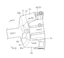
操作レバー1が中立位置にあるとき、図4に示すように、キャンセルレバー4の上面に形成された係合突起53と保持体3の係合面部42とが係合している。係合突起53は、ステアリングシャフト側に第1頂部53aを有する面が形成され、係合面部42は、係合突起53と当接する第2頂部42aを有する面が形成されている。ここで、係合突起53及び係合部42は、第1頂部53a及び第2頂部42a同士が当接され、キャンセルレバー4は、第3弾性部材14をさらに圧縮した状態でキャンセル突起6aの回動軌跡外に退出されている。したがって、キャンセルレバー4は、キャンセル突起6aの回動軌跡に向けてさらに大きな力で弾性付勢される。
When the operation lever 1 is in the neutral position, as shown in FIG. 4, the
以上のように、キャンセルレバー4がキャンセル突起6aの回転軌跡への進退動及び回動が可能となるように、圧縮状態にあるキャンセル用弾性部材14を介してキャンセルレバー4をハウジング2に設ける構成としたため、キャンセル用弾性部材14及びキャンセルレバー4をそれぞれひとつの部材で構成できるので、部品点数が少なく簡易な構造でキャンセル機構を構成できる。また、それら各部材を小さなスペースに配置することができるので、ターンシグナルスイッチ装置の小型化を図ることができる。さらに、第1駆動体10がカム部材5に弾接されるように、第1弾性部材11を介して第1駆動体10を操作レバー1の基部20に取付けたため、操作レバー1に対応する弾性部材とキャンセル機構に対応する弾性部材とを別々に構成できるので、設計の自由度を向上でき、フィーリングに優れたターンシグナルスイッチ装置を実現することができる。さらに、キャンセルレバー4が、2つの腕部51、52の間に形成される凹部4aと、ハウジング2の内面に向けて突出する下突部54とを有し、ハウジング2に、キャンセル突起61aの回動軌跡に対して下突部54を往復動可能に案内する案内長孔35が形成され、保持体3には、キャンセルレバー4の凹部4aの内側面に弾接されるように、第2弾性部材13を介して第2駆動体12が取付けられる構成としたので、後述するように、右折又は左折指示位置にラッチされた操作レバー1がたとえロックされても、右折又は左折後にハンドルの元の状態に戻すと、中立位置に操作レバー1を確実に自動復帰させることができる。
As described above, the cancel
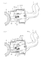
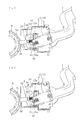
次に、図3〜図9に基づいてターンシグナルスイッチ装置の動作について説明する。図3〜図9の各図は、図1のターンシグナルスイッチ装置を裏側からみた図、すなわち、図1中の矢印A3の方向にみた図である。したがって、各図において、操作レバー1の左折指示の回動方向(図1のA1方向)は図中時計回りの方向であり、一方、操作レバー1の右折指示の回動方向(図1のA2方向)は図中反時計回りの方向である。各図において、一部の部品等を省略している。まず、操作レバー1が右折指示位置に回動操作されラッチされた後でハンドルを右方向に回動させて右折を行い、その後ハンドルを戻す方向(左方向)に回動させて操作レバー1が中立位置に自動復帰されるまでの動作を説明する。図3は、操作レバー1が中立位置から右折指示位置に回動操作される動作を説明する平面図である。 Next, operation | movement of a turn signal switch apparatus is demonstrated based on FIGS. 3 to 9 are views of the turn signal switch device of FIG. 1 as viewed from the back side, that is, as viewed in the direction of the arrow A3 in FIG. Accordingly, in each figure, the turning direction of the left turn instruction of the operation lever 1 (direction A1 in FIG. 1) is the clockwise direction in the figure, while the turning direction of the right turn instruction of the operation lever 1 (A2 in FIG. 1). Direction) is a counterclockwise direction in the figure. In each drawing, some parts are omitted. First, after the operating lever 1 is turned to the right turn instruction position and latched, the handle is turned to the right to make a right turn, and then the handle is turned back (to the left) to turn the operating lever 1. The operation until automatic return to the neutral position will be described. FIG. 3 is a plan view for explaining an operation in which the operation lever 1 is turned from the neutral position to the right turn instruction position.
リング状をなすキャンセルカム部材6の外縁部には、キャンセル突起6aが形成されている。したがって、キャンセル突起6aの回動軌跡は、キャンセルカム部材6の外縁部に沿ったものとなる。
A cancel
図3(a)は、操作レバー1が中立位置にある状態を示している。キャンセルレバー4は、係合突起53が保持体3の係合面部42に係合しており、キャンセルレバー4の突出部50がキャンセル突起6aの回転軌跡外に退出されている。図3(a)に示すように、キャンセルカム部材6のキャンセル突起6aは、キャンセルレバー4の突出部50の先端と対向している。
FIG. 3A shows a state where the operation lever 1 is in the neutral position. In the cancel
図4は、図3(a)の一部の拡大図である。図4において、A1方向またはA2方向に操作レバー1が回動操作されると、保持体3がB1方向またはB2方向に回動して、キャンセルレバー4がC3の方向に移動する。すなわち、キャンセルレバー4が第3弾性部材14によってステアリングシャフト側(図中C3方向)に向けて常時弾性付勢されるため(図2)、係合面部42が保持体3と一体的に回動すると、キャンセルレバー4の係合突起53が、係合面部42上を摺動して係合面部42の端部から外れるので、キャンセルレバー4がC3の方向に移動する。
FIG. 4 is an enlarged view of a part of FIG. In FIG. 4, when the operation lever 1 is rotated in the A1 direction or the A2 direction, the holding
図3(b)は、操作レバー1が右折指示位置に回動操作された状態を示している。操作レバー1が右折指示位置に回動操作されると、保持体3がB2方向に回動されて、前述のように係合突起53は、保持部36の係合面部42から外れた状態となり、キャンセルレバー4がC3の方向に移動する。この状態で、図2に示す第1駆動体10の先端部19aがカム面部60上を摺動してラッチ用突起61に係合し、操作レバー1がラッチされる。
FIG. 3B shows a state where the operation lever 1 is turned to the right turn instruction position. When the operation lever 1 is turned to the right turn instruction position, the holding
このとき、ハンドルが回転されていないため、C3方向に移動するキャンセルレバー4の突出部50先端は、キャンセル突起6aの外周面に当接されて押し付けられる。また、図2に示す被押圧部12aが、第1腕部51の第1押圧面部51aに当接、あるいは近接した状態となる。なお、このとき、キャンセルレバー4の下面側に形成された下突部54は、ハウジング2の案内長孔35内の中間に位置する。
At this time, since the handle is not rotated, the tip of the
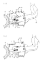
図5は、操作レバー1が右折指示位置から中立位置に自動復帰される途中までの動作を説明する平面図である。図5(a)は、図3(b)においてハンドルを右に回動させた状態を示している。ハンドルを右に回動させると、キャンセルカム部材6が右に回動して、キャンセル突起6aが突出部50の先端部から外れる。したがって、第3弾性部材14によって弾性付勢されたキャンセルレバー4がC3方向に移動して、突出部50がキャンセル突起6aの回動軌跡内に進出する。このとき、図2に示す下突部54(キャンセルレバー4)がハウジング2の案内長孔35内をC3方向に移動する。
FIG. 5 is a plan view for explaining the operation until the operation lever 1 is automatically returned from the right turn instruction position to the neutral position. FIG. 5A shows a state in which the handle is rotated to the right in FIG. When the handle is rotated to the right, the cancel
図5(b)は、右折するために右に回動させたハンドルを左に回動させて戻す過程を示している。図5(a)のようにハンドルを右回動させると、キャンセルレバー4の突出部50はキャンセル突起6aの回動軌跡内に進出するので、その後にハンドルを戻す途中で、キャンセル突起6aはキャンセルレバー4の突出部50の側面に当接する。
FIG. 5B shows a process in which the handle that has been turned right to turn right is turned back to the left. When the handle is rotated to the right as shown in FIG. 5A, the protruding
図6は、図5(b)の操作レバー1が中立位置に自動復帰されるまでの動作を説明する平面図である。図6(a)は、図5(b)の状態からさらにハンドルを左に回動させて戻した状態を示している。ハンドルを戻していくと、キャンセル突起6aによりキャンセルレバー4の突出部50の側面が押圧されて、キャンセルレバー4はC2方向に回動される。それにより、キャンセルレバー4の第1腕部51に形成された第1押圧面部51aは、保持体3に設けられた被押圧部12aをB1方向に押圧する。したがって、操作レバー1はA1方向に回動されるため、第1駆動体10の先端部10aがカム面部60のラッチ用突起61を乗り越えてラッチ状態が解除され、第1駆動体10の付勢力により保持体3が元の位置に自動的に戻るので、操作レバー1は中立位置に自動復帰する。
FIG. 6 is a plan view for explaining the operation until the operation lever 1 of FIG. 5B is automatically returned to the neutral position. FIG. 6A shows a state where the handle is further rotated leftward from the state of FIG. 5B. When the handle is returned, the side surface of the protruding
なお、保持体3が元の位置に戻るように回動されると、図6(a)の状態から図6(b)の状態へと変わる過程において、キャンセルレバー4の係合突起53は、保持体3の係合面部42の端部に当接して乗り上げる。そして係合突起53は、係合面部42によってキャンセル突起6aの回動軌跡から離れる方向に押圧され回動されながら図3(a)の状態に戻る。図6(b)は、ハンドルを中立位置まで戻して操作レバー1のキャンセル動作が終了した状態を示している。図6(b)における各部品の配置は、図3(a)と同じである。
In addition, when the holding
このように、操作レバー1を右折指示位置に回動操作させてラッチさせハンドルを右回転させて右折し、その後にハンドルを戻す際に、キャンセルレバー4の動作により、操作レバー1が中立位置に自動復帰される。なお、本発明に係るターンシグナルスイッチ装置は、何らかの原因で操作レバー1が右折指示位置でラッチされた状態でロックされた場合、キャンセルレバー4がキャンセル突起6aから所定の大きさ以上の力を受けて回動され、キャンセル動作が行われるように構成されている。その動作について説明する。
In this way, when the operation lever 1 is turned to the right turn instruction position and latched, the handle is rotated to the right and then turned to the right, and then the handle is returned, the operation lever 1 is moved to the neutral position by the operation of the cancel
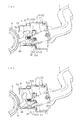
図7は、右折指示位置でロックされた操作レバー1が中立位置に自動復帰される動作を説明する平面図である。操作レバー1がラッチされた状態でロックされた場合、ハンドルを戻すと、保持体3は回動しないので、キャンセルレバー4は、図中時計回りに回動するキャンセル突起6aから所定以上の力を受けて、第1押圧面部51aが被押圧部12a(図2)を操作レバー1側へ押圧して移動させながらC2方向に回動される。すなわち、図2に示すように、第2駆動体12が第2弾性部材13を介して保持体3に取付けられているので、キャンセルレバー4が、第1押圧面部51aを介してキャンセル突起6aによって所定以上の力で押圧されると、被押圧部12aは、操作レバー1側に向かって移動される。
FIG. 7 is a plan view for explaining the operation of automatically returning the operation lever 1 locked at the right turn instruction position to the neutral position. When the operation lever 1 is locked in the latched state, the holding
このように、保持体3が回動しない状態でキャンセルレバー4が回動すると、図7(a)に示すように、キャンセルレバー4の押圧面部51aが第2弾性部材13の弾性付勢力に抗して被押圧部12aを押圧するため、キャンセルレバー4はC2方向に回動される。
In this way, when the cancel
図7(a)の状態においてさらにハンドルを戻すと、図7(b)に示すように、キャンセルレバー4がさらにC2方向に回動される。この状態で、被押圧部12aとキャンセルレバー4の第1腕部51との当接位置が、第1押圧面部51aから第2押圧面部51bへと移動し、突出部50の先端部はキャンセル突起6aの外周面に摺接するようになる。キャンセルレバー4が回動を続けると、突出部50がキャンセル突起6aから外れて、第2弾性部材13の弾性付勢力によって、キャンセルレバー4と操作レバー1が元の位置(図3(a)に示す位置)に戻りキャンセル動作が終了する。このように、操作レバー1が右折支持位置にロックされた状態でハンドルを左回転させて戻すと、キャンセルレバー4は回動し続けることができ、突出部50をキャンセル突起6aの回転軌跡から待避させることができるので、部品の破損を防止することができる。なお、ラッチされた操作レバー1は、図7(a)の状態から図7(b)の状態へと変わる過程において、ラッチが解除される。
When the handle is further returned in the state of FIG. 7A, the cancel
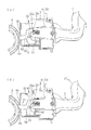
次に、図8と図9に基づいて、左折指示位置でラッチされた操作レバー1が中立位置に自動復帰される動作を簡単に説明する。まず、操作レバー1を図3(a)の状態から左折指示位置に回動させると、保持体3がB1方向に回動するのに伴い、保持体3の係合面部42とキャンセルレバー4の係合突起53との係合が解除されて、キャンセルレバー4の突出部50がキャンセル突起6aの回動軌跡に向けて進み、キャンセル突起6aの外周面に当接する。この状態でハンドルを左に回動させて左折を行うと、キャンセル突起6aも回動して、キャンセルレバー4の突出部50は、第3弾性部材14の弾性付勢力によりキャンセル突起6aの回転軌跡内に進出する。
Next, based on FIG. 8 and FIG. 9, the operation of automatically returning the operation lever 1 latched at the left turn instruction position to the neutral position will be briefly described. First, when the operating lever 1 is rotated from the state of FIG. 3A to the left turn instruction position, the engaging
図8は、操作レバー1が左折指示位置から中立位置に自動復帰される動作を説明する平面図である。図8(a)は、左に回動されたハンドルを右方向に回動させて戻す際、キャンセル突起6aがキャンセルレバー4の突出部50に当接した状態を示している。図8(b)は、ハンドルをさらに右方向に回転させたときの状態を示す。図8(b)において、キャンセルレバー4はC1方向に回動されるため、第2腕部52の第1押圧面部52aによって被押圧部12aが図中時計回りの方向に押圧される。したがって、保持体3はB2方向に回動されて、操作レバー1がA2方向に回動される。
FIG. 8 is a plan view for explaining the operation of automatically returning the operation lever 1 from the left turn instruction position to the neutral position. FIG. 8A shows a state in which the cancel
ハンドルがさらに右方向に回動されると、左折指示位置にある操作レバー1のラッチ状態が解除される。そして、操作レバー1は、中立位置に自動復帰するようにA2方向に回動されて、操作レバー1及びキャンセルレバー4が図6(b)と同じ状態に自動復帰して、キャンセル動作が終了する。
When the handle is further rotated to the right, the latched state of the operation lever 1 at the left turn instruction position is released. Then, the operation lever 1 is rotated in the A2 direction so as to automatically return to the neutral position, and the operation lever 1 and the cancel
図9は、左折指示位置でラッチされた状態でロックされた操作レバー1が中立位置に自動復帰される動作を説明する平面図である。ハンドルを右方向に回動させて戻すとき、図9(a)に示すように、キャンセルレバー4は、C1方向に回動されて、キャンセルレバー4の押圧面部52aが第2弾性部材13の弾性付勢力に抗して被押圧部12aを押圧して操作レバー1側に移動させる。
FIG. 9 is a plan view for explaining the operation in which the operation lever 1 locked in the latched state at the left turn instruction position is automatically returned to the neutral position. When the handle is rotated rightward and returned, as shown in FIG. 9A, the cancel
図9(a)の状態において、さらにハンドルを右方向に回動させて戻すと、図9(b)に示すように、キャンセルレバー4がさらにC1方向に回動されて、突出部50の先端部がキャンセル突起6aの外周部に摺接される。そして、キャンセルレバー4が回動を続けることで、突出部50がキャンセル突起6aの回転軌跡から退出される。これにより、操作レバー1がロックされていても、キャンセルレバー4が回動でき、部品の破損を防止できる。
In the state of FIG. 9A, when the handle is further rotated to the right and returned, the cancel
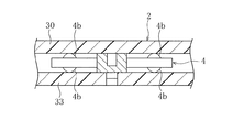
図10は、突起部4bを有するキャンセルレバー4とハウジング2との関係を説明する模式的断面図である。図10に示すように、キャンセルレバー4と上ケース30の内面及び下ケース33の内面との間に形成されるクリアランス部分に、キャンセルレバー4に形成した突起部4b(振動抑制手段)が存在すると、自動車の振動が加わってもキャンセルレバー4の動きが抑制されるので、異音が発生するのを防止できる。突起部4bは、先端が球面状に形成されていると、キャンセルレバー4がスムーズに回動するので好ましい。なお、突起部はキャンセルレバー4の上下両面に形成されていてもよいし、いずれか一方の面に形成されていてもよい。また、突起部は、キャンセルレバー4には形成されず、上ケース30の内面または下ケース33の内面に形成されていてもよい。
FIG. 10 is a schematic cross-sectional view for explaining the relationship between the cancel
図11は、キャンセルレバー4と吸音部材2aを有するハウジング2との関係を説明する模式的断面図である。図11に示すように、キャンセルレバー4の上下面とそれぞれ対向する上ケース30の内面及び下ケース33の内面に、吸音部材2aが設けられていると、自動車の振動などでキャンセルレバーが加振されても、異音が発生するのを防止できる。
FIG. 11 is a schematic cross-sectional view illustrating the relationship between the cancel
図12には、吸音部材4cを備えたキャンセルレバー4の斜視図を示している。吸音部材4cは、図11のようにハウジング2に設けるのではなく、キャンセルレバー4の上下面、すなわち上ケース30の内面及び下ケース33の内面と対向する面の、一方あるいは両面に設けられていても良い。
FIG. 12 shows a perspective view of the cancel
本実施形態のターンシグナルスイッチ装置は、以上のように、キャンセルレバー4がキャンセル突起6aの回転軌跡への進退動及び回動が可能となるように、圧縮状態にあるキャンセル用弾性部材36を介してキャンセルレバー4をハウジング2に設ける構成としたため、キャンセル用弾性部材36及びキャンセルレバー4をそれぞれひとつの部材で構成できるので、部品点数が少なく簡易な構造でキャンセル機構を構成できる。また、それら各部材を小さなスペースに配置させることができるので、ターンシグナルスイッチ装置の小型化を図ることができる。さらに、第1駆動体10がカム部材5に弾接されるように、第1弾性部材11を介して第1駆動体10を操作レバー1の基部20に取付けたため、操作レバー1に対応する弾性部材とキャンセル機構に対応する弾性部材とを別々に構成できるので、設計の自由度を向上でき、フィーリングに優れたターンシグナルスイッチ装置を実現することができる。
As described above, the turn signal switch device according to the present embodiment has the cancel
以上、本発明の実施形態について説明したが、本発明の適用は本実施形態には限られず、その技術的思想の範囲内において様々に適用されうるものである。 Although the embodiment of the present invention has been described above, the application of the present invention is not limited to this embodiment, and can be applied in various ways within the scope of its technical idea.
1 操作レバー
2 ハウジング
3 保持体
4 キャンセルレバー
4a 凹部
4b 突起部(振動抑制手段)
4c 吸音部材
5 カム部材
6 キャンセルカム部材
6a キャンセル突起
10 第1駆動体
11 第1弾性部材
12 第2駆動体
12a 被押圧部
13 第2弾性部材
14 第3弾性部材(キャンセル用弾性部材)
20 基部
21 操作部
30 上ケース
33 下ケース
35 案内長孔
36 第3弾性部材保持部(キャンセルレバー保持部)
40 本体部
41 突出面部
41a 第2駆動体挿通孔(挿通孔部)
42 係合面部
42a 第2頂部
43 挿入ピン
50 突出部
51 第1腕部
51a 第1押圧面部
51b 第2押圧面部
52 第2腕部
52a 第1押圧面部
52b 第2押圧面部
53 係合突起
53a 第1頂部
54 下突部
55 保持部
60 カム面部
60a 中央部
60b 傾斜面
61 ラッチ用突起
DESCRIPTION OF SYMBOLS 1
4c
20
40
42
Claims (7)
前記ハウジング内に、前記操作レバーの基部と対向するようにカム部材が設けられ、前記操作レバーの基部には、前記カム部材に弾接されるように、第1弾性部材を介して第1駆動体が取付けられ、
前記カム部材は、前記操作レバーが中立位置にあるときに前記第1駆動体を係止する中央部と、前記操作レバーが少なくとも左折指示位置及び右折指示位置のいずれかの位置にあるときに、前記第1駆動体を係止するラッチ用突起と、前記中央部及び前記ラッチ用突起が形成されている位置以外において、前記中央部へ向けて前記第1駆動体を弾性付勢するように形成された傾斜面とを有し、
前記キャンセルレバーは、圧縮状態にあるキャンセル用弾性部材を介して前記ハウジング内に設けられ、かつ、前記回転軌跡側に第1頂部を有する面が形成された係合突起を備え、
前記保持体は、前記操作レバーが前記中立位置にあるとき、前記係合突起と当接する第2頂部を有する面が形成された係合部を備え、
前記操作レバーが前記中立位置にあるとき、前記係合突起及び前記係合部は、第1頂部及び第2頂部同士が当接され、前記キャンセルレバーは、前記回転軌跡外に退出されていることを特徴とするターンシグナルスイッチ装置。 An operation lever, a holding body that rotatably supports the base of the operation lever on one plane, a housing that rotatably supports the holding body on another plane that intersects the one plane, And a cancel lever capable of moving back and forth and rotating to the rotation locus of the cancel projection provided on the steering shaft,
A cam member is provided in the housing so as to face the base of the operation lever, and the base of the operation lever is first driven through a first elastic member so as to be elastically contacted with the cam member. The body is installed and
The cam member, when the operation lever is in a neutral position, the central portion that locks the first drive body, and when the operation lever is at least one of a left turn instruction position and a right turn instruction position, Formed so as to elastically bias the first driving body toward the central portion other than the position of the latching projection for locking the first driving body and the central portion and the latching projection. An inclined surface,
The cancel lever is provided in the housing via a canceling elastic member in a compressed state, and includes an engaging protrusion having a surface having a first top on the rotation locus side,
The holding body includes an engaging portion formed with a surface having a second top portion that comes into contact with the engaging protrusion when the operation lever is in the neutral position.
When the operation lever is in the neutral position, the engaging protrusion and the engaging portion are in contact with each other between the first top portion and the second top portion, and the cancel lever is retracted out of the rotation locus. A turn signal switch device.
Priority Applications (1)
| Application Number | Priority Date | Filing Date | Title |
|---|---|---|---|
| JP2012038865A JP5811462B2 (en) | 2011-02-25 | 2012-02-24 | Turn signal switch device |
Applications Claiming Priority (3)
| Application Number | Priority Date | Filing Date | Title |
|---|---|---|---|
| JP2011039728 | 2011-02-25 | ||
| JP2011039728 | 2011-02-25 | ||
| JP2012038865A JP5811462B2 (en) | 2011-02-25 | 2012-02-24 | Turn signal switch device |
Publications (2)
| Publication Number | Publication Date |
|---|---|
| JP2012190796A true JP2012190796A (en) | 2012-10-04 |
| JP5811462B2 JP5811462B2 (en) | 2015-11-11 |
Family
ID=45656256
Family Applications (1)
| Application Number | Title | Priority Date | Filing Date |
|---|---|---|---|
| JP2012038865A Active JP5811462B2 (en) | 2011-02-25 | 2012-02-24 | Turn signal switch device |
Country Status (5)
| Country | Link |
|---|---|
| US (1) | US8822856B2 (en) |
| EP (1) | EP2492142B1 (en) |
| JP (1) | JP5811462B2 (en) |
| KR (1) | KR101359282B1 (en) |
| CN (1) | CN102651289B (en) |
Cited By (2)
| Publication number | Priority date | Publication date | Assignee | Title |
|---|---|---|---|---|
| JP2018107082A (en) * | 2016-12-28 | 2018-07-05 | 株式会社ヴァレオジャパン | Lever device |
| US11004629B2 (en) | 2019-03-07 | 2021-05-11 | Toyo Denso Kabushiki Kaisha | Lever switch mounted on a vehicle |
Families Citing this family (5)
| Publication number | Priority date | Publication date | Assignee | Title |
|---|---|---|---|---|
| JP6117026B2 (en) * | 2013-07-04 | 2017-04-19 | アルプス電気株式会社 | Operation lever device |
| JP6765839B2 (en) * | 2016-04-06 | 2020-10-07 | アルプスアルパイン株式会社 | Input control device |
| JP2017190005A (en) * | 2016-04-12 | 2017-10-19 | アルプス電気株式会社 | Input operation device |
| JP7145106B2 (en) * | 2019-03-07 | 2022-09-30 | 東洋電装株式会社 | Auto-cancellation mechanism of turn signal switch device |
| JP2021138253A (en) * | 2020-03-04 | 2021-09-16 | 株式会社東海理化電機製作所 | Switch device |
Family Cites Families (17)
| Publication number | Priority date | Publication date | Assignee | Title |
|---|---|---|---|---|
| DE1655798C3 (en) * | 1967-06-03 | 1974-02-21 | Westfaelische Metall Industrie Kg, Hueck & Co, 4780 Lippstadt | Switches for direction indicators of motor vehicles |
| JPH08167346A (en) * | 1994-12-12 | 1996-06-25 | Matsushita Electric Ind Co Ltd | Turn flasher switch |
| JPH0950735A (en) * | 1995-08-07 | 1997-02-18 | Niles Parts Co Ltd | Cancel mechanism of turn signal switch for vehicle |
| JPH10203234A (en) * | 1997-01-20 | 1998-08-04 | Tokai Rika Co Ltd | Turn signal cancellation mechanism |
| JPH10269901A (en) | 1997-03-21 | 1998-10-09 | Alps Electric Co Ltd | Turn signal switch |
| DE19758288B4 (en) * | 1997-12-31 | 2006-10-26 | Valeo Schalter Und Sensoren Gmbh | Method and device for the rotationally-coupled reset of a switch |
| FR2780925B1 (en) * | 1998-07-13 | 2000-09-29 | Valeo Electronique | INDICATOR SWITCH WITH EXHAUST RETURN DEVICE |
| JP3784542B2 (en) * | 1998-07-28 | 2006-06-14 | アルプス電気株式会社 | Turn signal switch |
| JP2002225625A (en) * | 2001-01-29 | 2002-08-14 | Yazaki Corp | Turn signal switch |
| JP2003127762A (en) * | 2001-10-19 | 2003-05-08 | Alps Electric Co Ltd | Turn signal switch device |
| JP2003127764A (en) * | 2001-10-24 | 2003-05-08 | Niles Parts Co Ltd | Cancel structure of combination switch |
| FR2851965B1 (en) * | 2003-03-07 | 2006-04-28 | Delphi Tech Inc | DEVICE FOR UNLOCKING A DIRECTION CHANGE INDICATOR |
| JP4139317B2 (en) * | 2003-11-27 | 2008-08-27 | 株式会社東海理化電機製作所 | Vehicle direction indication device |
| JP4652356B2 (en) * | 2007-02-26 | 2011-03-16 | アルプス電気株式会社 | Turn signal switch device |
| KR100930129B1 (en) | 2007-12-05 | 2009-12-07 | 주식회사 신창전기 | Bracket for turn signal switch of automobile |
| JP2009173198A (en) | 2008-01-25 | 2009-08-06 | Tokai Rika Co Ltd | Vehicular turn lever switch device |
| JP5509832B2 (en) * | 2009-12-17 | 2014-06-04 | パナソニック株式会社 | Turning direction indicator |
-
2012
- 2012-02-15 KR KR1020120015305A patent/KR101359282B1/en active IP Right Grant
- 2012-02-21 EP EP12156295.3A patent/EP2492142B1/en active Active
- 2012-02-23 CN CN201210042933.8A patent/CN102651289B/en active Active
- 2012-02-24 US US13/405,031 patent/US8822856B2/en active Active
- 2012-02-24 JP JP2012038865A patent/JP5811462B2/en active Active
Cited By (2)
| Publication number | Priority date | Publication date | Assignee | Title |
|---|---|---|---|---|
| JP2018107082A (en) * | 2016-12-28 | 2018-07-05 | 株式会社ヴァレオジャパン | Lever device |
| US11004629B2 (en) | 2019-03-07 | 2021-05-11 | Toyo Denso Kabushiki Kaisha | Lever switch mounted on a vehicle |
Also Published As
| Publication number | Publication date |
|---|---|
| EP2492142A3 (en) | 2018-04-11 |
| KR101359282B1 (en) | 2014-02-05 |
| JP5811462B2 (en) | 2015-11-11 |
| EP2492142A2 (en) | 2012-08-29 |
| EP2492142B1 (en) | 2020-07-01 |
| CN102651289A (en) | 2012-08-29 |
| KR20120098425A (en) | 2012-09-05 |
| US20120217142A1 (en) | 2012-08-30 |
| CN102651289B (en) | 2014-10-22 |
| US8822856B2 (en) | 2014-09-02 |
Similar Documents
| Publication | Publication Date | Title |
|---|---|---|
| JP5811462B2 (en) | Turn signal switch device | |
| JP2006221933A (en) | Turn signal lamp switch device | |
| JP2012195103A (en) | Turn signal switch device | |
| JP2007012365A (en) | Stoking switch | |
| JP6765839B2 (en) | Input control device | |
| JP6581515B2 (en) | Input operation device | |
| US5949040A (en) | Turn signal switch | |
| JP2008071580A (en) | Stalk switch device | |
| JP6721675B2 (en) | Input operation device | |
| JP2008192417A (en) | Turn signal switch device | |
| JP2017190005A (en) | Input operation device | |
| JP2003127764A (en) | Cancel structure of combination switch | |
| JP4284121B2 (en) | Turn signal switch device | |
| JP4230349B2 (en) | Turn signal switch device | |
| JP6613180B2 (en) | Turn signal switch device | |
| JP6152314B2 (en) | Vehicle control device | |
| JPH09132081A (en) | Cansel device of turn signal switch | |
| JP4481784B2 (en) | Lever switch device for vehicle | |
| JP2009140709A (en) | Turn signal switch device | |
| JP2008097865A (en) | Stoke switch device | |
| JP2006248434A (en) | Turn signal switch device | |
| JP4238090B2 (en) | Turn signal switch device | |
| JP2001006494A (en) | Stalk switch device | |
| JP2009143376A (en) | Turn signal switch device | |
| JP2009205966A (en) | Turn signal switch device |
Legal Events
| Date | Code | Title | Description |
|---|---|---|---|
| A621 | Written request for application examination |
Free format text: JAPANESE INTERMEDIATE CODE: A621 Effective date: 20141023 |
|
| A977 | Report on retrieval |
Free format text: JAPANESE INTERMEDIATE CODE: A971007 Effective date: 20150714 |
|
| A131 | Notification of reasons for refusal |
Free format text: JAPANESE INTERMEDIATE CODE: A131 Effective date: 20150721 |
|
| A521 | Written amendment |
Free format text: JAPANESE INTERMEDIATE CODE: A523 Effective date: 20150728 |
|
| TRDD | Decision of grant or rejection written | ||
| A01 | Written decision to grant a patent or to grant a registration (utility model) |
Free format text: JAPANESE INTERMEDIATE CODE: A01 Effective date: 20150831 |
|
| A61 | First payment of annual fees (during grant procedure) |
Free format text: JAPANESE INTERMEDIATE CODE: A61 Effective date: 20150903 |
|
| R150 | Certificate of patent or registration of utility model |
Ref document number: 5811462 Country of ref document: JP Free format text: JAPANESE INTERMEDIATE CODE: R150 |
|
| S533 | Written request for registration of change of name |
Free format text: JAPANESE INTERMEDIATE CODE: R313533 |
|
| R350 | Written notification of registration of transfer |
Free format text: JAPANESE INTERMEDIATE CODE: R350 |