JP2012190766A - Terminal and connector using the same - Google Patents
Terminal and connector using the same Download PDFInfo
- Publication number
- JP2012190766A JP2012190766A JP2011055727A JP2011055727A JP2012190766A JP 2012190766 A JP2012190766 A JP 2012190766A JP 2011055727 A JP2011055727 A JP 2011055727A JP 2011055727 A JP2011055727 A JP 2011055727A JP 2012190766 A JP2012190766 A JP 2012190766A
- Authority
- JP
- Japan
- Prior art keywords
- movable contact
- terminal
- contact
- housing
- press
- Prior art date
- Legal status (The legal status is an assumption and is not a legal conclusion. Google has not performed a legal analysis and makes no representation as to the accuracy of the status listed.)
- Granted
Links
Images


Classifications
-
- H—ELECTRICITY
- H01—ELECTRIC ELEMENTS
- H01R—ELECTRICALLY-CONDUCTIVE CONNECTIONS; STRUCTURAL ASSOCIATIONS OF A PLURALITY OF MUTUALLY-INSULATED ELECTRICAL CONNECTING ELEMENTS; COUPLING DEVICES; CURRENT COLLECTORS
- H01R13/00—Details of coupling devices of the kinds covered by groups H01R12/70 or H01R24/00 - H01R33/00
- H01R13/02—Contact members
- H01R13/22—Contacts for co-operating by abutting
- H01R13/24—Contacts for co-operating by abutting resilient; resiliently-mounted
-
- H—ELECTRICITY
- H01—ELECTRIC ELEMENTS
- H01R—ELECTRICALLY-CONDUCTIVE CONNECTIONS; STRUCTURAL ASSOCIATIONS OF A PLURALITY OF MUTUALLY-INSULATED ELECTRICAL CONNECTING ELEMENTS; COUPLING DEVICES; CURRENT COLLECTORS
- H01R12/00—Structural associations of a plurality of mutually-insulated electrical connecting elements, specially adapted for printed circuits, e.g. printed circuit boards [PCB], flat or ribbon cables, or like generally planar structures, e.g. terminal strips, terminal blocks; Coupling devices specially adapted for printed circuits, flat or ribbon cables, or like generally planar structures; Terminals specially adapted for contact with, or insertion into, printed circuits, flat or ribbon cables, or like generally planar structures
- H01R12/50—Fixed connections
- H01R12/51—Fixed connections for rigid printed circuits or like structures
- H01R12/55—Fixed connections for rigid printed circuits or like structures characterised by the terminals
- H01R12/57—Fixed connections for rigid printed circuits or like structures characterised by the terminals surface mounting terminals
-
- H—ELECTRICITY
- H01—ELECTRIC ELEMENTS
- H01R—ELECTRICALLY-CONDUCTIVE CONNECTIONS; STRUCTURAL ASSOCIATIONS OF A PLURALITY OF MUTUALLY-INSULATED ELECTRICAL CONNECTING ELEMENTS; COUPLING DEVICES; CURRENT COLLECTORS
- H01R13/00—Details of coupling devices of the kinds covered by groups H01R12/70 or H01R24/00 - H01R33/00
- H01R13/02—Contact members
- H01R13/22—Contacts for co-operating by abutting
- H01R13/24—Contacts for co-operating by abutting resilient; resiliently-mounted
- H01R13/2407—Contacts for co-operating by abutting resilient; resiliently-mounted characterized by the resilient means
- H01R13/2428—Contacts for co-operating by abutting resilient; resiliently-mounted characterized by the resilient means using meander springs
Landscapes
- Connector Housings Or Holding Contact Members (AREA)
- Coupling Device And Connection With Printed Circuit (AREA)
- Connection Of Batteries Or Terminals (AREA)
Abstract
Description
本願発明は端子、例えば、ハウジングに組み込まれてコネクタを形成するだけでなく、基板の側端面に直接実装して使用できる端子に関する。 The present invention relates to a terminal, for example, a terminal that can be used by being directly mounted on a side end surface of a substrate, as well as being incorporated in a housing to form a connector.
従来、端子としては、例えば、導電性チューブ内に、導電性ピンを突出および後退方向に摺動自在でしかも抜け出ないように配設するとともに、前記導電性ピンを前記突出方向に弾性付勢するコイルスプリングを縮設してなるスプリングコネクタにおいて、前記コイルスプリングのすくなくとも一部分の巻き外径を1タ−ンずれた他部分の巻き内径より小さくまたは同じとなるように設定し、前記コイルスプリングが収縮された状態で、前記一部分を前記他部分の内側に収容し得るように構成したことを特徴とするスプリングコネクタがある(特許文献1参照)。
そして、特許文献1の図1に示すように、前述のスプリングコネクタ20では、導電性ピン14がコイルスプリング26で軸心方向に付勢されている。そして、その図5に示す、バッテリー44の当接端子46に圧接することにより、所定の接点圧を確保しつつ、電気的接続する構成となっている。
Conventionally, as a terminal, for example, a conductive pin is disposed in a conductive tube so as to be slidable in a protruding and retracting direction and not to be pulled out, and the conductive pin is elastically biased in the protruding direction. In the spring connector in which the coil spring is contracted, at least a part of the winding outer diameter of the coil spring is set to be smaller than or equal to the winding inner diameter of the other part shifted by one turn, and the coil spring contracts. In this state, there is a spring connector characterized in that the part can be accommodated inside the other part (see Patent Document 1).
As shown in FIG. 1 of
しかしながら、前述のスプリングコネクタでは、導電性ピンの先端面がバッテリーの接続パッドに接触する場合に、コイルスプリングのバネ力が接続パッドの先端面に局所的に集中するため、接続パッドの金メッキ層を破損するおそれがある。
また、大容量のバッテリーに前記スプリングコネクタを接続した場合、接触抵抗による発熱によって高温になりやすく、通電できる電流容量が低下するという問題点がある。
本発明に係る端子は、その可動接点部に対する付勢力を低下させずに接圧を軽減することにより、バッテリーの接続パッドの破損を防止できるとともに、可動接点部の発熱による通電容量の低下を防止できる端子を提供することを課題とする。
However, in the above-described spring connector, when the tip surface of the conductive pin contacts the connection pad of the battery, the spring force of the coil spring is concentrated locally on the tip surface of the connection pad. There is a risk of damage.
In addition, when the spring connector is connected to a large-capacity battery, there is a problem in that the current capacity that can be energized decreases because the temperature tends to increase due to heat generated by the contact resistance.
The terminal according to the present invention can prevent the connection pad of the battery from being damaged by reducing the contact pressure without reducing the urging force to the movable contact portion, and also prevent the current carrying capacity from being reduced due to heat generation of the movable contact portion. It is an object to provide a terminal that can be used.
本発明に係る端子は、前記課題を解決するために、ハウジングの接点孔から出し入れ可能に突出する可動接点部を有する端子であって、前記可動接点部の接点面を弾性変形可能な円弧状薄肉部で形成した構成としてある。 In order to solve the above-mentioned problem, the terminal according to the present invention is a terminal having a movable contact portion protruding so as to be able to be inserted and removed from a contact hole of a housing, and the arc-shaped thin wall capable of elastically deforming the contact surface of the movable contact portion. This is a configuration formed of parts.
本発明によれば、可動接点部の接点面がバッテリーのパッドに圧接した場合に弾性変形し、接触面積が増大することにより、可動接点部に対する付勢力を低下させずに接圧を低下させることができ、前記バッテリーの接続パッドの破損を防止できる。
また、可動接点部における露出面積が増大するので、冷却効率が向上し、高温になりにくく、通電できる電気容量が低下しにくい端子が得られる。
さらに、可動接点部の接点面を円弧状薄肉部で形成してあるので、前記可動接点部自体の質量が小さくなり、慣性力が小さくなる。このため、外部から衝撃力、例えば、落下による衝撃力がハウジングに負荷されても、可動接点部の慣性力で瞬間的に生じる電気的接続不良である瞬断を防止できる。
According to the present invention, the contact surface of the movable contact portion is elastically deformed when pressed against the battery pad, and the contact area is increased, thereby reducing the contact pressure without reducing the urging force against the movable contact portion. The battery connection pad can be prevented from being damaged.
Moreover, since the exposed area in the movable contact portion increases, a cooling efficiency is improved, and a terminal that is unlikely to become high temperature and that is less likely to have a reduced electric capacity can be obtained.
Furthermore, since the contact surface of the movable contact portion is formed of an arcuate thin portion, the mass of the movable contact portion itself is reduced and the inertial force is reduced. For this reason, even when an impact force, for example, an impact force due to dropping, is applied to the housing from the outside, it is possible to prevent a momentary disconnection, which is an electrical connection failure that occurs instantaneously due to the inertial force of the movable contact portion.
本発明の実施形態としては、前記円弧状薄肉部は均一な厚さを有していてもよい。
本実施形態によれば、プレス成形や電鋳加工で製造しやすい端子が得られる。
As an embodiment of the present invention, the arcuate thin portion may have a uniform thickness.
According to this embodiment, a terminal that can be easily manufactured by press molding or electroforming is obtained.
本発明の他の実施形態としては、円弧状薄肉部は基部に向かって順次、厚くなっていてもよい。
本実施形態によれば、円弧状薄肉部の基部に応力が集中しにくくなり、寿命の長い端子が得られる。
As another embodiment of the present invention, the arcuate thin portion may be gradually increased toward the base.
According to this embodiment, stress is less likely to concentrate on the base of the arcuate thin portion, and a terminal having a long life can be obtained.
本発明に係るコネクタは、前述の端子に係る可動接点部を、ハウジングに設けた接点孔から出し入れ可能に突出させた構成としてある。 The connector according to the present invention has a configuration in which the movable contact portion related to the terminal is protruded from a contact hole provided in the housing so as to be able to be taken in and out.
本発明によれば、可動接点部の接点面がバッテリーの接続パッドに圧接した場合に弾性変形し、接触面積が増大することにより、可動接点部に対する付勢力を低下させずに接圧を低下させることができるので、前記バッテリーの接続パッドの破損を防止できる。
また、可動接点部における露出面積が増大するので、冷却効率が向上し、高温になりにくく、通電できる電気容量が低下しにくいコネクタが得られる。
さらに、可動接点部の接点面を円弧状薄肉部で形成してあるので、前記可動接点部自体の質量が小さくなり、慣性力が小さくなる。このため、外部から衝撃力、例えば、落下による衝撃力がハウジングに負荷されても、可動接点部の慣性力で瞬間的に生じる電気的接続不良である瞬断を防止できる。
According to the present invention, when the contact surface of the movable contact portion comes into pressure contact with the connection pad of the battery, it is elastically deformed and the contact area increases, thereby reducing the contact pressure without reducing the urging force against the movable contact portion. Therefore, the battery connection pad can be prevented from being damaged.
Further, since the exposed area in the movable contact portion increases, a cooling efficiency is improved, and a connector that is unlikely to become high temperature and that is less likely to have a reduced electric capacity can be obtained.
Furthermore, since the contact surface of the movable contact portion is formed of an arcuate thin portion, the mass of the movable contact portion itself is reduced and the inertial force is reduced. For this reason, even when an impact force, for example, an impact force due to dropping, is applied to the housing from the outside, it is possible to prevent a momentary disconnection, which is an electrical connection failure that occurs instantaneously due to the inertial force of the movable contact portion.
本発明に係るコネクタの実施形態としては、被接触物の押圧時に可動接点部の接点面が弾性変形する構成としてもよい。
本実施形態によれば、応力が集中しにくくなり、寿命の長いコネクタが得られるという効果がある。
As an embodiment of the connector according to the present invention, the contact surface of the movable contact portion may be elastically deformed when the contacted object is pressed.
According to this embodiment, it is difficult to concentrate stress, and there is an effect that a connector having a long life can be obtained.
本発明に係る端子の実施形態を図1ないし図8の添付図面に従って説明する。
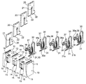
本実施形態は、図1ないし図5に示すように、樹脂成形された高さ4mmのハウジング10に所定のピッチで固定金具20を圧入するとともに、前記固定金具20,20の間に接続端子30を圧入したコネクタに適用した場合である。
A terminal according to an embodiment of the present invention will be described with reference to the accompanying drawings of FIGS.
In the present embodiment, as shown in FIGS. 1 to 5, the
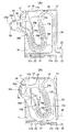
前記ハウジング10は、図2に示すように、固定金具20を上方から圧入できる第1収納スペース11を所定ピッチで設けてあるとともに、前記第1収納スペース11の対向する内側面には係止用突条12を設けてある。また、前記ハウジング10は、前記第1収納スペース11,11の間に接続端子30を背面側から圧入できる3つの第2収納スペース13を並設してある。特に、両端に設けた第2収納スペース13は、仕切り壁13aで仕切られている。さらに、前記ハウジング10は、その正面側に、前記第2収納スペース13に連通し、かつ、後述する可動接点部36を出し入れできる接点孔14を設けてあるとともに、前記第2収納スペース13に連通する圧入孔15を設けてある。そして、前記接点孔14の両側開口縁部に補強用リブ16を突設するとともに、前記接点孔14の上方縁部に位置規制用受け部17を形成してある。また、前記ハウジング10は、その上面の正面側縁部に前記第2収納スペース13に連通する覗き孔18を設けてある。
As shown in FIG. 2, the
固定金具20は、図3Aに示すように、金属製薄板をプレス加工で打ち抜いて形成した略門型のプレス成形品であり、その内側面に係止爪21を突設してある。このため、前記ハウジング10の第1収納スペース11に前記固定金具20を上方から圧入すると、前記係止爪21が前記ハウジング10の係止用突条12に係止し、前記固定金具20が抜け止めされるとともに、前記固定金具20の固定用下端部22が前記ハウジング10の底面から接続固定できるように露出する(図5)。
As shown in FIG. 3A, the
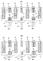
接続端子30は、図3Bに示すように、圧入用固定部31から上方に略J形状の支持部32を突出するとともに、前記支持部32の先端に位置する第1分岐部33aから第1延在部34aと第2分岐部33bとが延在し、前記第2分岐部33bから第2,第3延在部34b,34cが分岐している。
前記圧入用固定部31には、その一端部の上面に係止爪31aを突設してある一方、その他端部の下面から接続部31bを設けることにより、圧入用切り欠き部31cを形成してある。
また、前記第1分岐部33a,第2分岐部33bから分岐した第1,第2,第3延在部34a,34b,34cが略平行に蛇行するように延在することにより、第1,第2スリット35a,35bを形成してある。このため、分岐部33a,33bに対する応力集中が生じにくくなり、寿命が伸びるとともに、設計の自由度が広がるという利点がある。
さらに、前記第1,第2,第3延在部34a,34b,34cの先端部を一体化して形成した自由端部に可動接点部36を設けてあるとともに、前記第1延在部34aの先端に位置規制用突部37を突設してある。前記可動接点部36は、その接点面36aを弾性変形可能な円弧状薄肉部38で形成してある。なお、前記円弧状薄肉部38は弾性変形可能であればよく、均一な厚さを有する場合だけでなく、基部に向かって順次、厚くなるように形成してもよい。
As shown in FIG. 3B, the
The press-
Further, the first, second, and third extending
Furthermore, a
なお、本実施形態では、第1,第2,第3延在部34a,34b,34cの湾曲部分における厚さ寸法を順次、大きくしてある。このため、動作時における応力集中が生じにくくなり、寿命が伸びるという利点がある。
また、本実施形態に係る第1,第2スリット35a,35bの巾寸法は、接続端子30の可動接点部36を動作させても第1,第2,第3延在部34a,34b,34cが相互に接触しない大きさとなっている。このため、所定の動作時において第1,第2,第3延在部34a,34b,34cが相互に接触することがなく、不快な接触音が生じない。
さらに、前記可動接点部36の可動接点面36aを弾性変形可能な円弧状薄肉部で形成してあるので、可動接点面36aの背後に冷却用貫通孔が形成され、露出面積が増大している。このため、接触抵抗に基づいて発熱しても、効率的に冷却でき、可動接点部36が高温になりにくいという利点がある。
In the present embodiment, the thickness dimensions of the curved portions of the first, second, and third extending
Further, the width dimensions of the first and
Further, since the
そして、図1に示すように、前記ハウジング10の第2収納スペース13に背面側から前記接続端子30を挿入する。そして、前記圧入用固定部31を圧入孔15に圧入し、係止爪31aを圧入孔15の内面に係止するとともに、切り欠き部31cをハウジング10の縁部に係合することにより、固定できる。これにより、接続端子30の位置規制用突部37がハウジング10の位置規制用受け部17に当接して位置規制されるとともに、接続端子30の接続部31bが固定金具20の固定用下端部22と面一となる。
Then, as shown in FIG. 1, the
ついで、図示しないプリント基板に実装した前記コネクタに、例えば、携帯電子機器のバッテリーを圧接させることにより、可動接点部36を押し込むと、第1,第2,第3延在部34a,34b,34cが弾性変形するとともに、支持部32が弾性変形する。そして、所定の押し込み量の範囲内であれば、第1,第2スリット35a,35bの巾寸法を大きくしてあるので、第1,第2,第3延在部34a,34b,34cが相互に接触することがなく、摩擦音を発生させることがない。特に、可動接点部36と圧入用固定部31との間に、蛇行する第1,第2,第3延在部34a,34b,34cおよび支持部32が配置され、バネ長が長いので、所望の変位量を確保できるとともに、応力集中が生じにくい。このため、接触信頼性が向上するとともに、寿命の長いコネクタが得られる。
また、接触抵抗に基づいて可動接点部36が発熱しても、冷却用貫通孔38aを設けてあるので、効率的に冷却でき、高温になりにくいという利点がある。
Next, when the
Even if the
なお、前述の実施形態では、接触信頼性を高めるために2枚1組の接続端子と1枚の接続端子とを組み合わせる場合について説明したが、全て1枚の接続端子だけで構成してもよく、あるいは、全て2枚1組の接続端子で構成してもよい。さらに、3枚1組で接続端子を組み込んでも良く、必要に応じて接続端子の数を選択できることは勿論である。
また、延在部およびスリットは一様な巾寸法である必要はなく、必要に応じて巾寸法を変化させてもよい。例えば、延在部の湾曲部分のうち、外側の位置する延在部の湾曲部分の巾寸法だけを大きくし、応力集中の発生を防止することにより、耐久性を高めてもよい。
さらに、前記実施形態では、ハウジングに接続端子を組み込む場合について説明したが、プリント基板自体をハウジングとし、その側端面に本願の接続端子を直接組み込んでもよい。これによれば、前述のハウジングおよび固定金具を必要とせず、結果として装置全体をより一層小型化できるという利点がある。
In the above-described embodiment, the case where a set of two connection terminals and a single connection terminal are combined in order to improve contact reliability has been described. However, all may be configured with only one connection terminal. Alternatively, all of them may be composed of a set of two connection terminals. Further, the connection terminals may be incorporated in a set of three, and the number of connection terminals can be selected as needed.
Further, the extending portion and the slit need not have a uniform width dimension, and the width dimension may be changed as necessary. For example, the durability may be enhanced by increasing only the width dimension of the curved portion of the extending portion located outside of the curved portion of the extending portion to prevent the occurrence of stress concentration.
Furthermore, although the case where the connection terminal is incorporated in the housing has been described in the above embodiment, the connection board of the present application may be incorporated directly on the side end surface of the printed circuit board itself as the housing. According to this, there is an advantage that the above-described housing and fixing bracket are not required, and as a result, the entire apparatus can be further reduced in size.
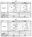
ヘルツの理論式を用い、円弧状薄肉部が均一な厚さを有する場合(図6A,図7)と、円弧状薄肉部の厚さが基部に向かって厚くなる場合(図6B,図8)とにおける接触圧力の変換を計算した結果をそれぞれ図6A,図6Bに示す。
(実施例1)
Using Hertz's theoretical formula, the arcuate thin part has a uniform thickness (FIGS. 6A and 7), and the arcuate thin part increases in thickness toward the base (FIGS. 6B and 8). 6A and 6B show the results of calculation of contact pressure conversion in FIGS.
Example 1
すなわち、円弧状薄肉部を厚さ0.1mm、接点面における曲率半径を0.5mm、その基部における厚さを0.1mmとした場合に、バネ力として接触力0.9Nを負荷したとき、接点面の曲率半径が0.5mmから0.7mmに変化するとともに、接圧が1210(N/mm2)から967(N/mm2)に低下することが判った。これにより、同じ接触力であっても、接点面の曲率半径が大きくなることで、被接触物との接触面積が大きくなり、局所的な応力集中が緩和され、バッテリーの接続パッドの破損を防止できることが判った。
(実施例2)
That is, when a contact force of 0.9 N is applied as a spring force when the arcuate thin portion is 0.1 mm thick, the radius of curvature at the contact surface is 0.5 mm, and the thickness at the base is 0.1 mm, It was found that the curvature radius of the contact surface changed from 0.5 mm to 0.7 mm, and the contact pressure decreased from 1210 (N / mm 2 ) to 967 (N / mm 2 ). As a result, even if the contact force is the same, the radius of curvature of the contact surface increases, increasing the contact area with the contacted object, reducing local stress concentration and preventing damage to the battery connection pads. I found that I can do it.
(Example 2)
円弧状薄肉部の接点面において厚さ0.1mm、接点面における曲率半径を0.5mm、その基部における厚さを0.17mmとした場合に、バネ力として接触力0.9Nを負荷したとき、接点面の曲率半径が0.5mmから0.85mmに変化するとともに、接圧が1210(N/mm2)から849(N/mm2)に低下することが判った。これにより、前述と同様、接点面の曲率半径がより大きくなることで、被接触物との接触面積がより大きくなり、局所的な応力集中が緩和され、バッテリーの接続パッドの破損を防止できることが判った。 When a contact force of 0.9 N is applied as a spring force when the contact surface of the arcuate thin portion is 0.1 mm thick, the radius of curvature at the contact surface is 0.5 mm, and the thickness at the base is 0.17 mm. It was found that the radius of curvature of the contact surface changed from 0.5 mm to 0.85 mm, and the contact pressure decreased from 1210 (N / mm 2 ) to 849 (N / mm 2 ). As described above, this increases the radius of curvature of the contact surface, thereby increasing the contact area with the contacted object, reducing local stress concentration, and preventing damage to the battery connection pads. understood.
なお、円弧状薄肉部の厚さが基部に向かって薄くなる場合には、バネ力として接触力を負荷しても、接点面の曲率半径は変化せず、局所的な応力集中の緩和を図ることはできなかった。
したがって、円弧状薄肉部が被接触物を押圧したときに弾性変形する条件は、円弧状薄肉部が均一な厚さを有する場合、もしくは、円弧状薄肉部の厚さが基部に向かって厚くなる場合である。
When the thickness of the arcuate thin portion decreases toward the base, even if a contact force is applied as a spring force, the curvature radius of the contact surface does not change, and local stress concentration is alleviated. I couldn't.
Accordingly, the condition for the elastic deformation when the arcuate thin part presses the contacted object is that the arcuate thin part has a uniform thickness or the thickness of the arcuate thin part increases toward the base. Is the case.
本発明に係る端子は、前述の形状に限らず、可動接点部の接点面を弾性変形可能な円弧状薄肉部で形成したものであれば、特に限定するものではない。 The terminal according to the present invention is not limited to the above-described shape, and is not particularly limited as long as the contact surface of the movable contact portion is formed of an arcuate thin portion that can be elastically deformed.
10:ハウジング
13:第2収納スペース
14:接点孔
17:位置規制用受け部
20:固定金具
30:接続端子
31:圧入用固定部
32:支持部
33a,33b:第1分岐部,第2分岐部
34a,34b,34c:第1,第2,第3延在部
35a,35b:第1,第2スリット
36:可動接点部
36a:接点面
37:位置規制用突部
38:円弧状薄肉部
38a:冷却用貫通孔
10: Housing 13: Second storage space 14: Contact hole 17: Position restricting receiving portion 20: Fixing bracket 30: Connection terminal 31: Press fitting fixing portion 32:
本願発明は端子、例えば、ハウジングに組み込まれてコネクタを形成するだけでなく、基板の側端面に直接実装して使用できる端子に関する。 The present invention relates to a terminal, for example, a terminal that can be used by being directly mounted on a side end surface of a substrate, as well as being incorporated in a housing to form a connector.
従来、端子としては、例えば、導電性チューブ内に、導電性ピンを突出および後退方向に摺動自在でしかも抜け出ないように配設するとともに、前記導電性ピンを前記突出方向に弾性付勢するコイルスプリングを縮設してなるスプリングコネクタにおいて、前記コイルスプリングのすくなくとも一部分の巻き外径を1タ−ンずれた他部分の巻き内径より小さくまたは同じとなるように設定し、前記コイルスプリングが収縮された状態で、前記一部分を前記他部分の内側に収容し得るように構成したことを特徴とするスプリングコネクタがある(特許文献1参照)。
そして、特許文献1の図1に示すように、前述のスプリングコネクタ20では、導電性ピン14がコイルスプリング26で軸心方向に付勢されている。そして、その図5に示す、バッテリー44の当接端子46に圧接することにより、所定の接点圧を確保しつつ、電気的接続する構成となっている。
Conventionally, as a terminal, for example, a conductive pin is disposed in a conductive tube so as to be slidable in a protruding and retracting direction and not to be pulled out, and the conductive pin is elastically biased in the protruding direction. In the spring connector in which the coil spring is contracted, at least a part of the winding outer diameter of the coil spring is set to be smaller than or equal to the winding inner diameter of the other part shifted by one turn, and the coil spring contracts. In this state, there is a spring connector characterized in that the part can be accommodated inside the other part (see Patent Document 1).
As shown in FIG. 1 of
しかしながら、前述のスプリングコネクタでは、導電性ピンの先端面がバッテリーの接続パッドに接触する場合に、コイルスプリングのバネ力が接続パッドの先端面に局所的に集中するため、接続パッドの金メッキ層を破損するおそれがある。
また、大容量のバッテリーに前記スプリングコネクタを接続した場合、接触抵抗による発熱によって高温になりやすく、通電できる電流容量が低下するという問題点がある。
本発明に係る端子は、その可動接点部に対する付勢力を低下させずに接圧を軽減することにより、バッテリーの接続パッドの破損を防止できるとともに、可動接点部の発熱による通電容量の低下を防止できる端子を提供することを課題とする。
However, in the above-described spring connector, when the tip surface of the conductive pin contacts the connection pad of the battery, the spring force of the coil spring is concentrated locally on the tip surface of the connection pad. There is a risk of damage.
In addition, when the spring connector is connected to a large-capacity battery, there is a problem in that the current capacity that can be energized decreases because the temperature tends to increase due to heat generated by the contact resistance.
The terminal according to the present invention can prevent the connection pad of the battery from being damaged by reducing the contact pressure without reducing the urging force to the movable contact portion, and also prevent the current carrying capacity from being reduced due to heat generation of the movable contact portion. It is an object to provide a terminal that can be used.
本発明に係る端子は、前記課題を解決するために、ハウジングの接点孔から出し入れ可能に突出する可動接点部を有する端子であって、前記可動接点部の接点面を、均一な厚さを有し、かつ、弾性変形可能な円弧状薄肉部で形成するとともに、前記可動接点部の両端を、少なくとも2本の略平行に蛇行する弾性変形可能な延在部で支持した構成としてある。 In order to solve the above problems, the terminal according to the present invention is a terminal having a movable contact portion that protrudes from a contact hole of a housing so as to be able to be inserted and removed, and the contact surface of the movable contact portion has a uniform thickness. In addition, while being formed of an elastically deformable arc-shaped thin part, both ends of the movable contact part are supported by at least two elastically deformable extending parts meandering in parallel .
本発明によれば、可動接点部の接点面がバッテリーのパッドに圧接した場合に弾性変形し、接触面積が増大することにより、可動接点部に対する付勢力を低下させずに接圧を低下させることができ、前記バッテリーの接続パッドの破損を防止できる。
また、可動接点部における露出面積が増大するので、冷却効率が向上し、高温になりにくく、通電できる電気容量が低下しにくい端子が得られる。
さらに、可動接点部の接点面を円弧状薄肉部で形成してあるので、前記可動接点部自体の質量が小さくなり、慣性力が小さくなる。このため、外部から衝撃力、例えば、落下による衝撃力がハウジングに負荷されても、可動接点部の慣性力で瞬間的に生じる電気的接続不良である瞬断を防止できる。
そして、プレス成形や電鋳加工で製造しやすい端子が得られる。
According to the present invention, the contact surface of the movable contact portion is elastically deformed when pressed against the battery pad, and the contact area is increased, thereby reducing the contact pressure without reducing the urging force against the movable contact portion. The battery connection pad can be prevented from being damaged.
Moreover, since the exposed area in the movable contact portion increases, a cooling efficiency is improved, and a terminal that is unlikely to become high temperature and that is less likely to have a reduced electric capacity can be obtained.
Furthermore, since the contact surface of the movable contact portion is formed of an arcuate thin portion, the mass of the movable contact portion itself is reduced and the inertial force is reduced. For this reason, even when an impact force, for example, an impact force due to dropping, is applied to the housing from the outside, it is possible to prevent a momentary disconnection, which is an electrical connection failure that occurs instantaneously due to the inertial force of the movable contact portion.
And the terminal which is easy to manufacture by press molding or electroforming is obtained.
本発明に係る他の端子は、ハウジングの接点孔から出し入れ可能に突出する可動接点部を有する端子であって、前記可動接点部の接点面を、基部に向かって順次、厚くなり、かつ、弾性変形可能な円弧状薄肉部で形成するとともに、前記可動接点部の両端を、少なくとも2本の略平行に蛇行する弾性変形可能な延在部で支持した構成としてある。Another terminal according to the present invention is a terminal having a movable contact portion protruding so as to be able to be inserted and removed from a contact hole of the housing, and the contact surface of the movable contact portion is gradually increased toward the base portion and is elastic. The movable contact portion is formed by a deformable arc-shaped thin portion, and both ends of the movable contact portion are supported by at least two elastically deformable extending portions meandering in parallel.
本発明によれば、円弧状薄肉部の基部に応力が集中しにくくなり、寿命の長い端子が得られる。 According to the present invention , stress is less likely to concentrate at the base of the arcuate thin portion, and a terminal having a long life can be obtained.
本発明に係るコネクタは、前述の端子に係る可動接点部を、ハウジングに設けた接点孔から出し入れ可能に突出させた構成としてある。 The connector according to the present invention has a configuration in which the movable contact portion related to the terminal is protruded from a contact hole provided in the housing so as to be able to be taken in and out.
本発明によれば、可動接点部の接点面がバッテリーの接続パッドに圧接した場合に弾性変形し、接触面積が増大することにより、可動接点部に対する付勢力を低下させずに接圧を低下させることができるので、前記バッテリーの接続パッドの破損を防止できる。
また、可動接点部における露出面積が増大するので、冷却効率が向上し、高温になりにくく、通電できる電気容量が低下しにくいコネクタが得られる。
さらに、可動接点部の接点面を円弧状薄肉部で形成してあるので、前記可動接点部自体の質量が小さくなり、慣性力が小さくなる。このため、外部から衝撃力、例えば、落下による衝撃力がハウジングに負荷されても、可動接点部の慣性力で瞬間的に生じる電気的接続不良である瞬断を防止できる。
According to the present invention, when the contact surface of the movable contact portion comes into pressure contact with the connection pad of the battery, it is elastically deformed and the contact area increases, thereby reducing the contact pressure without reducing the urging force against the movable contact portion. Therefore, the battery connection pad can be prevented from being damaged.
Further, since the exposed area in the movable contact portion increases, a cooling efficiency is improved, and a connector that is unlikely to become high temperature and that is less likely to have a reduced electric capacity can be obtained.
Furthermore, since the contact surface of the movable contact portion is formed of an arcuate thin portion, the mass of the movable contact portion itself is reduced and the inertial force is reduced. For this reason, even when an impact force, for example, an impact force due to dropping, is applied to the housing from the outside, it is possible to prevent a momentary disconnection, which is an electrical connection failure that occurs instantaneously due to the inertial force of the movable contact portion.
本発明に係るコネクタの実施形態としては、被接触物の押圧時に可動接点部の接点面が弾性変形する構成としてもよい。
本実施形態によれば、応力が集中しにくくなり、寿命の長いコネクタが得られるという効果がある。
As an embodiment of the connector according to the present invention, the contact surface of the movable contact portion may be elastically deformed when the contacted object is pressed.
According to this embodiment, it is difficult to concentrate stress, and there is an effect that a connector having a long life can be obtained.
本発明に係る端子の実施形態を図1ないし図8の添付図面に従って説明する。
本実施形態は、図1ないし図5に示すように、樹脂成形された高さ4mmのハウジング10に所定のピッチで固定金具20を圧入するとともに、前記固定金具20,20の間に接続端子30を圧入したコネクタに適用した場合である。
A terminal according to an embodiment of the present invention will be described with reference to the accompanying drawings of FIGS.
In the present embodiment, as shown in FIGS. 1 to 5, the fixing
前記ハウジング10は、図2に示すように、固定金具20を上方から圧入できる第1収納スペース11を所定ピッチで設けてあるとともに、前記第1収納スペース11の対向する内側面には係止用突条12を設けてある。また、前記ハウジング10は、前記第1収納スペース11,11の間に接続端子30を背面側から圧入できる3つの第2収納スペース13を並設してある。特に、両端に設けた第2収納スペース13は、仕切り壁13aで仕切られている。さらに、前記ハウジング10は、その正面側に、前記第2収納スペース13に連通し、かつ、後述する可動接点部36を出し入れできる接点孔14を設けてあるとともに、前記第2収納スペース13に連通する圧入孔15を設けてある。そして、前記接点孔14の両側開口縁部に補強用リブ16を突設するとともに、前記接点孔14の上方縁部に位置規制用受け部17を形成してある。また、前記ハウジング10は、その上面の正面側縁部に前記第2収納スペース13に連通する覗き孔18を設けてある。
As shown in FIG. 2, the
固定金具20は、図3Aに示すように、金属製薄板をプレス加工で打ち抜いて形成した略門型のプレス成形品であり、その内側面に係止爪21を突設してある。このため、前記ハウジング10の第1収納スペース11に前記固定金具20を上方から圧入すると、前記係止爪21が前記ハウジング10の係止用突条12に係止し、前記固定金具20が抜け止めされるとともに、前記固定金具20の固定用下端部22が前記ハウジング10の底面から接続固定できるように露出する(図5)。
As shown in FIG. 3A, the
接続端子30は、図3Bに示すように、圧入用固定部31から上方に略J形状の支持部32を突出するとともに、前記支持部32の先端に位置する第1分岐部33aから第1延在部34aと第2分岐部33bとが延在し、前記第2分岐部33bから第2,第3延在部34b,34cが分岐している。
前記圧入用固定部31には、その一端部の上面に係止爪31aを突設してある一方、その他端部の下面から接続部31bを設けることにより、圧入用切り欠き部31cを形成してある。
また、前記第1分岐部33a,第2分岐部33bから分岐した第1,第2,第3延在部34a,34b,34cが略平行に蛇行するように延在することにより、第1,第2スリット35a,35bを形成してある。このため、分岐部33a,33bに対する応力集中が生じにくくなり、寿命が伸びるとともに、設計の自由度が広がるという利点がある。
さらに、前記第1,第2,第3延在部34a,34b,34cの先端部を一体化して形成した自由端部に可動接点部36を設けてあるとともに、前記第1延在部34aの先端に位置規制用突部37を突設してある。前記可動接点部36は、その接点面36aを弾性変形可能な円弧状薄肉部38で形成してある。なお、前記円弧状薄肉部38は弾性変形可能であればよく、均一な厚さを有する場合だけでなく、基部に向かって順次、厚くなるように形成してもよい。
As shown in FIG. 3B, the
The press-
Further, the first, second, and third extending
Furthermore, a
なお、本実施形態では、第1,第2,第3延在部34a,34b,34cの湾曲部分における厚さ寸法を順次、大きくしてある。このため、動作時における応力集中が生じにくくなり、寿命が伸びるという利点がある。
また、本実施形態に係る第1,第2スリット35a,35bの巾寸法は、接続端子30の可動接点部36を動作させても第1,第2,第3延在部34a,34b,34cが相互に接触しない大きさとなっている。このため、所定の動作時において第1,第2,第3延在部34a,34b,34cが相互に接触することがなく、不快な接触音が生じない。
さらに、前記可動接点部36の可動接点面36aを弾性変形可能な円弧状薄肉部で形成してあるので、可動接点面36aの背後に冷却用貫通孔が形成され、露出面積が増大している。このため、接触抵抗に基づいて発熱しても、効率的に冷却でき、可動接点部36が高温になりにくいという利点がある。
In the present embodiment, the thickness dimensions of the curved portions of the first, second, and third extending
Further, the width dimensions of the first and
Further, since the
そして、図1に示すように、前記ハウジング10の第2収納スペース13に背面側から前記接続端子30を挿入する。そして、前記圧入用固定部31を圧入孔15に圧入し、係止爪31aを圧入孔15の内面に係止するとともに、切り欠き部31cをハウジング10の縁部に係合することにより、固定できる。これにより、接続端子30の位置規制用突部37がハウジング10の位置規制用受け部17に当接して位置規制されるとともに、接続端子30の接続部31bが固定金具20の固定用下端部22と面一となる。
Then, as shown in FIG. 1, the
ついで、図示しないプリント基板に実装した前記コネクタに、例えば、携帯電子機器のバッテリーを圧接させることにより、可動接点部36を押し込むと、第1,第2,第3延在部34a,34b,34cが弾性変形するとともに、支持部32が弾性変形する。そして、所定の押し込み量の範囲内であれば、第1,第2スリット35a,35bの巾寸法を大きくしてあるので、第1,第2,第3延在部34a,34b,34cが相互に接触することがなく、摩擦音を発生させることがない。特に、可動接点部36と圧入用固定部31との間に、蛇行する第1,第2,第3延在部34a,34b,34cおよび支持部32が配置され、バネ長が長いので、所望の変位量を確保できるとともに、応力集中が生じにくい。このため、接触信頼性が向上するとともに、寿命の長いコネクタが得られる。
また、接触抵抗に基づいて可動接点部36が発熱しても、冷却用貫通孔38aを設けてあるので、効率的に冷却でき、高温になりにくいという利点がある。
Next, when the
Even if the
なお、前述の実施形態では、接触信頼性を高めるために2枚1組の接続端子と1枚の接続端子とを組み合わせる場合について説明したが、全て1枚の接続端子だけで構成してもよく、あるいは、全て2枚1組の接続端子で構成してもよい。さらに、3枚1組で接続端子を組み込んでも良く、必要に応じて接続端子の数を選択できることは勿論である。
また、延在部およびスリットは一様な巾寸法である必要はなく、必要に応じて巾寸法を変化させてもよい。例えば、延在部の湾曲部分のうち、外側の位置する延在部の湾曲部分の巾寸法だけを大きくし、応力集中の発生を防止することにより、耐久性を高めてもよい。
さらに、前記実施形態では、ハウジングに接続端子を組み込む場合について説明したが、プリント基板自体をハウジングとし、その側端面に本願の接続端子を直接組み込んでもよい。これによれば、前述のハウジングおよび固定金具を必要とせず、結果として装置全体をより一層小型化できるという利点がある。
In the above-described embodiment, the case where a set of two connection terminals and a single connection terminal are combined in order to improve contact reliability has been described. However, all may be configured with only one connection terminal. Alternatively, all of them may be composed of a set of two connection terminals. Further, the connection terminals may be incorporated in a set of three, and the number of connection terminals can be selected as needed.
Further, the extending portion and the slit need not have a uniform width dimension, and the width dimension may be changed as necessary. For example, the durability may be enhanced by increasing only the width dimension of the curved portion of the extending portion located outside of the curved portion of the extending portion to prevent the occurrence of stress concentration.
Furthermore, although the case where the connection terminal is incorporated in the housing has been described in the above embodiment, the connection board of the present application may be incorporated directly on the side end surface of the printed circuit board itself as the housing. According to this, there is an advantage that the above-described housing and fixing bracket are not required, and as a result, the entire apparatus can be further reduced in size.
ヘルツの理論式を用い、円弧状薄肉部が均一な厚さを有する場合(図6A,図7)と、円弧状薄肉部の厚さが基部に向かって厚くなる場合(図6B,図8)とにおける接触圧力の変換を計算した結果をそれぞれ図6A,図6Bに示す。
(実施例1)
Using Hertz's theoretical formula, the arcuate thin part has a uniform thickness (FIGS. 6A and 7), and the arcuate thin part increases in thickness toward the base (FIGS. 6B and 8). 6A and 6B show the results of calculation of contact pressure conversion in FIGS.
Example 1
すなわち、円弧状薄肉部を厚さ0.1mm、接点面における曲率半径を0.5mm、その基部における厚さを0.1mmとした場合に、バネ力として接触力0.9Nを負荷したとき、接点面の曲率半径が0.5mmから0.7mmに変化するとともに、接圧が1210(N/mm2)から967(N/mm2)に低下することが判った。これにより、同じ接触力であっても、接点面の曲率半径が大きくなることで、被接触物との接触面積が大きくなり、局所的な応力集中が緩和され、バッテリーの接続パッドの破損を防止できることが判った。
(実施例2)
That is, when a contact force of 0.9 N is applied as a spring force when the arcuate thin portion is 0.1 mm thick, the radius of curvature at the contact surface is 0.5 mm, and the thickness at the base is 0.1 mm, It was found that the curvature radius of the contact surface changed from 0.5 mm to 0.7 mm, and the contact pressure decreased from 1210 (N / mm 2 ) to 967 (N / mm 2 ). As a result, even if the contact force is the same, the radius of curvature of the contact surface increases, increasing the contact area with the contacted object, reducing local stress concentration and preventing damage to the battery connection pads. I found that I can do it.
(Example 2)
円弧状薄肉部の接点面において厚さ0.1mm、接点面における曲率半径を0.5mm、その基部における厚さを0.17mmとした場合に、バネ力として接触力0.9Nを負荷したとき、接点面の曲率半径が0.5mmから0.85mmに変化するとともに、接圧が1210(N/mm2)から849(N/mm2)に低下することが判った。これにより、前述と同様、接点面の曲率半径がより大きくなることで、被接触物との接触面積がより大きくなり、局所的な応力集中が緩和され、バッテリーの接続パッドの破損を防止できることが判った。 When a contact force of 0.9 N is applied as a spring force when the contact surface of the arcuate thin portion is 0.1 mm thick, the radius of curvature at the contact surface is 0.5 mm, and the thickness at the base is 0.17 mm. It was found that the radius of curvature of the contact surface changed from 0.5 mm to 0.85 mm, and the contact pressure decreased from 1210 (N / mm 2 ) to 849 (N / mm 2 ). As described above, this increases the radius of curvature of the contact surface, thereby increasing the contact area with the contacted object, reducing local stress concentration, and preventing damage to the battery connection pads. understood.
なお、円弧状薄肉部の厚さが基部に向かって薄くなる場合には、バネ力として接触力を負荷しても、接点面の曲率半径は変化せず、局所的な応力集中の緩和を図ることはできなかった。
したがって、円弧状薄肉部が被接触物を押圧したときに弾性変形する条件は、円弧状薄肉部が均一な厚さを有する場合、もしくは、円弧状薄肉部の厚さが基部に向かって厚くなる場合である。
When the thickness of the arcuate thin portion decreases toward the base, even if a contact force is applied as a spring force, the curvature radius of the contact surface does not change, and local stress concentration is alleviated. I couldn't.
Accordingly, the condition for the elastic deformation when the arcuate thin part presses the contacted object is that the arcuate thin part has a uniform thickness or the thickness of the arcuate thin part increases toward the base. Is the case.
本発明に係る端子は、前述の形状に限らず、可動接点部の接点面を弾性変形可能な円弧状薄肉部で形成したものであれば、特に限定するものではない。 The terminal according to the present invention is not limited to the above-described shape, and is not particularly limited as long as the contact surface of the movable contact portion is formed of an arcuate thin portion that can be elastically deformed.
10:ハウジング
13:第2収納スペース
14:接点孔
17:位置規制用受け部
20:固定金具
30:接続端子
31:圧入用固定部
32:支持部
33a,33b:第1分岐部,第2分岐部
34a,34b,34c:第1,第2,第3延在部
35a,35b:第1,第2スリット
36:可動接点部
36a:接点面
37:位置規制用突部
38:円弧状薄肉部
38a:冷却用貫通孔
10: Housing 13: Second storage space 14: Contact hole 17: Position restricting receiving portion 20: Fixing bracket 30: Connection terminal 31: Press fitting fixing portion 32:
本願発明は端子、例えば、ハウジングに組み込まれてコネクタを形成するだけでなく、基板の側端面に直接実装して使用できる端子に関する。 The present invention relates to a terminal, for example, a terminal that can be used by being directly mounted on a side end surface of a substrate, as well as being incorporated in a housing to form a connector.
従来、端子としては、例えば、導電性チューブ内に、導電性ピンを突出および後退方向に摺動自在でしかも抜け出ないように配設するとともに、前記導電性ピンを前記突出方向に弾性付勢するコイルスプリングを縮設してなるスプリングコネクタにおいて、前記コイルスプリングのすくなくとも一部分の巻き外径を1タ−ンずれた他部分の巻き内径より小さくまたは同じとなるように設定し、前記コイルスプリングが収縮された状態で、前記一部分を前記他部分の内側に収容し得るように構成したことを特徴とするスプリングコネクタがある(特許文献1参照)。
そして、特許文献1の図1に示すように、前述のスプリングコネクタ20では、導電性ピン14がコイルスプリング26で軸心方向に付勢されている。そして、その図5に示す、バッテリー44の当接端子46に圧接することにより、所定の接点圧を確保しつつ、電気的接続する構成となっている。
Conventionally, as a terminal, for example, a conductive pin is disposed in a conductive tube so as to be slidable in a protruding and retracting direction and not to be pulled out, and the conductive pin is elastically biased in the protruding direction. In the spring connector in which the coil spring is contracted, at least a part of the winding outer diameter of the coil spring is set to be smaller than or equal to the winding inner diameter of the other part shifted by one turn, and the coil spring contracts. In this state, there is a spring connector characterized in that the part can be accommodated inside the other part (see Patent Document 1).
As shown in FIG. 1 of
しかしながら、前述のスプリングコネクタでは、導電性ピンの先端面がバッテリーの接続パッドに接触する場合に、コイルスプリングのバネ力が接続パッドの先端面に局所的に集中するため、接続パッドの金メッキ層を破損するおそれがある。
また、大容量のバッテリーに前記スプリングコネクタを接続した場合、接触抵抗による発熱によって高温になりやすく、通電できる電流容量が低下するという問題点がある。
本発明に係る端子は、その可動接点部に対する付勢力を低下させずに接圧を軽減することにより、バッテリーの接続パッドの破損を防止できるとともに、可動接点部の発熱による通電容量の低下を防止できる端子を提供することを課題とする。
However, in the above-described spring connector, when the tip surface of the conductive pin contacts the connection pad of the battery, the spring force of the coil spring is concentrated locally on the tip surface of the connection pad. There is a risk of damage.
In addition, when the spring connector is connected to a large-capacity battery, there is a problem in that the current capacity that can be energized decreases because the temperature tends to increase due to heat generated by the contact resistance.
The terminal according to the present invention can prevent the connection pad of the battery from being damaged by reducing the contact pressure without reducing the urging force to the movable contact portion, and also prevent the current carrying capacity from being reduced due to heat generation of the movable contact portion. It is an object to provide a terminal that can be used.
本発明に係る端子は、前記課題を解決するために、ハウジングの接点孔から出し入れ可能に突出する可動接点部を有する端子であって、前記可動接点部の接点面を、均一な厚さを有し、かつ、被接触物との接触時に前記接点面の曲率半径が増大するように弾性変形可能な円弧状薄肉部で形成するとともに、前記可動接点部の両端を、少なくとも2本の略平行に蛇行する弾性変形可能な延在部で支持した構成としてある。 In order to solve the above problems, the terminal according to the present invention is a terminal having a movable contact portion that protrudes from a contact hole of a housing so as to be able to be inserted and removed, and the contact surface of the movable contact portion has a uniform thickness. And an arc-shaped thin portion that can be elastically deformed so that the radius of curvature of the contact surface increases when contacting the contacted object, and at least two substantially parallel ends of the movable contact portion. The structure is supported by a meandering elastically deformable extension.
本発明によれば、可動接点部の接点面がバッテリーのパッドに圧接した場合に弾性変形し、接触面積が増大することにより、可動接点部に対する付勢力を低下させずに接圧を低下させることができ、前記バッテリーの接続パッドの破損を防止できる。
また、可動接点部における露出面積が増大するので、冷却効率が向上し、高温になりにくく、通電できる電気容量が低下しにくい端子が得られる。
さらに、可動接点部の接点面を円弧状薄肉部で形成してあるので、前記可動接点部自体の質量が小さくなり、慣性力が小さくなる。このため、外部から衝撃力、例えば、落下による衝撃力がハウジングに負荷されても、可動接点部の慣性力で瞬間的に生じる電気的接続不良である瞬断を防止できる。
そして、プレス成形や電鋳加工で製造しやすい端子が得られる。
According to the present invention, the contact surface of the movable contact portion is elastically deformed when pressed against the battery pad, and the contact area is increased, thereby reducing the contact pressure without reducing the urging force against the movable contact portion. The battery connection pad can be prevented from being damaged.
Moreover, since the exposed area in the movable contact portion increases, a cooling efficiency is improved, and a terminal that is unlikely to become high temperature and that is less likely to have a reduced electric capacity can be obtained.
Furthermore, since the contact surface of the movable contact portion is formed of an arcuate thin portion, the mass of the movable contact portion itself is reduced and the inertial force is reduced. For this reason, even when an impact force, for example, an impact force due to dropping, is applied to the housing from the outside, it is possible to prevent a momentary disconnection, which is an electrical connection failure that occurs instantaneously due to the inertial force of the movable contact portion.
And the terminal which is easy to manufacture by press molding or electroforming is obtained.
本発明に係る他の端子は、ハウジングの接点孔から出し入れ可能に突出する可動接点部を有する端子であって、
前記可動接点部の接点面を、基部に向かって順次、厚くなり、かつ、被接触物との接触時に前記接点面の曲率半径が増大するように弾性変形可能な円弧状薄肉部で形成するとともに、前記可動接点部の両端を、少なくとも2本の略平行に蛇行する弾性変形可能な延在部で支持した構成としてある。
Another terminal according to the present invention is a terminal having a movable contact portion protruding so as to be able to be taken in and out from the contact hole of the housing,
The contact surface of the movable contact portion is formed with an arcuate thin portion that can be elastically deformed so that the contact surface gradually becomes thicker toward the base and the radius of curvature of the contact surface increases when contacting the contacted object. The movable contact portion is supported at both ends by at least two elastically deformable extending portions that meander in parallel.
本発明によれば、円弧状薄肉部の基部に応力が集中しにくくなり、寿命の長い端子が得られる。 According to the present invention, stress is less likely to concentrate at the base of the arcuate thin portion, and a terminal having a long life can be obtained.
本発明に係るコネクタは、前述の端子に係る可動接点部を、ハウジングに設けた接点孔から出し入れ可能に突出させた構成としてある。 The connector according to the present invention has a configuration in which the movable contact portion related to the terminal is protruded from a contact hole provided in the housing so as to be able to be taken in and out.
本発明によれば、可動接点部の接点面がバッテリーの接続パッドに圧接した場合に弾性変形し、接触面積が増大することにより、可動接点部に対する付勢力を低下させずに接圧を低下させることができるので、前記バッテリーの接続パッドの破損を防止できる。
また、可動接点部における露出面積が増大するので、冷却効率が向上し、高温になりにくく、通電できる電気容量が低下しにくいコネクタが得られる。
さらに、可動接点部の接点面を円弧状薄肉部で形成してあるので、前記可動接点部自体の質量が小さくなり、慣性力が小さくなる。このため、外部から衝撃力、例えば、落下による衝撃力がハウジングに負荷されても、可動接点部の慣性力で瞬間的に生じる電気的接続不良である瞬断を防止できる。
According to the present invention, when the contact surface of the movable contact portion comes into pressure contact with the connection pad of the battery, it is elastically deformed and the contact area increases, thereby reducing the contact pressure without reducing the urging force against the movable contact portion. Therefore, the battery connection pad can be prevented from being damaged.
Further, since the exposed area in the movable contact portion increases, a cooling efficiency is improved, and a connector that is unlikely to become high temperature and that is less likely to have a reduced electric capacity can be obtained.
Furthermore, since the contact surface of the movable contact portion is formed of an arcuate thin portion, the mass of the movable contact portion itself is reduced and the inertial force is reduced. For this reason, even when an impact force, for example, an impact force due to dropping, is applied to the housing from the outside, it is possible to prevent a momentary disconnection, which is an electrical connection failure that occurs instantaneously due to the inertial force of the movable contact portion.
本発明に係るコネクタの実施形態としては、被接触物の押圧時に可動接点部の接点面が弾性変形する構成としてもよい。
本実施形態によれば、応力が集中しにくくなり、寿命の長いコネクタが得られるという効果がある。
As an embodiment of the connector according to the present invention, the contact surface of the movable contact portion may be elastically deformed when the contacted object is pressed.
According to this embodiment, it is difficult to concentrate stress, and there is an effect that a connector having a long life can be obtained.
本発明に係る端子の実施形態を図1ないし図8の添付図面に従って説明する。
本実施形態は、図1ないし図5に示すように、樹脂成形された高さ4mmのハウジング10に所定のピッチで固定金具20を圧入するとともに、前記固定金具20,20の間に接続端子30を圧入したコネクタに適用した場合である。
A terminal according to an embodiment of the present invention will be described with reference to the accompanying drawings of FIGS.
In the present embodiment, as shown in FIGS. 1 to 5, the fixing
前記ハウジング10は、図2に示すように、固定金具20を上方から圧入できる第1収納スペース11を所定ピッチで設けてあるとともに、前記第1収納スペース11の対向する内側面には係止用突条12を設けてある。また、前記ハウジング10は、前記第1収納スペース11,11の間に接続端子30を背面側から圧入できる3つの第2収納スペース13を並設してある。特に、両端に設けた第2収納スペース13は、仕切り壁13aで仕切られている。さらに、前記ハウジング10は、その正面側に、前記第2収納スペース13に連通し、かつ、後述する可動接点部36を出し入れできる接点孔14を設けてあるとともに、前記第2収納スペース13に連通する圧入孔15を設けてある。そして、前記接点孔14の両側開口縁部に補強用リブ16を突設するとともに、前記接点孔14の上方縁部に位置規制用受け部17を形成してある。また、前記ハウジング10は、その上面の正面側縁部に前記第2収納スペース13に連通する覗き孔18を設けてある。
As shown in FIG. 2, the
固定金具20は、図3Aに示すように、金属製薄板をプレス加工で打ち抜いて形成した略門型のプレス成形品であり、その内側面に係止爪21を突設してある。このため、前記ハウジング10の第1収納スペース11に前記固定金具20を上方から圧入すると、前記係止爪21が前記ハウジング10の係止用突条12に係止し、前記固定金具20が抜け止めされるとともに、前記固定金具20の固定用下端部22が前記ハウジング10の底面から接続固定できるように露出する(図5)。
As shown in FIG. 3A, the
接続端子30は、図3Bに示すように、圧入用固定部31から上方に略J形状の支持部32を突出するとともに、前記支持部32の先端に位置する第1分岐部33aから第1延在部34aと第2分岐部33bとが延在し、前記第2分岐部33bから第2,第3延在部34b,34cが分岐している。
前記圧入用固定部31には、その一端部の上面に係止爪31aを突設してある一方、その他端部の下面から接続部31bを設けることにより、圧入用切り欠き部31cを形成してある。
また、前記第1分岐部33a,第2分岐部33bから分岐した第1,第2,第3延在部34a,34b,34cが略平行に蛇行するように延在することにより、第1,第2スリット35a,35bを形成してある。このため、分岐部33a,33bに対する応力集中が生じにくくなり、寿命が伸びるとともに、設計の自由度が広がるという利点がある。
さらに、前記第1,第2,第3延在部34a,34b,34cの先端部を一体化して形成した自由端部に可動接点部36を設けてあるとともに、前記第1延在部34aの先端に位置規制用突部37を突設してある。前記可動接点部36は、その接点面36aを弾性変形可能な円弧状薄肉部38で形成してある。なお、前記円弧状薄肉部38は弾性変形可能であればよく、均一な厚さを有する場合だけでなく、基部に向かって順次、厚くなるように形成してもよい。
As shown in FIG. 3B, the
The press-
Further, the first, second, and third extending
Furthermore, a
なお、本実施形態では、第1,第2,第3延在部34a,34b,34cの湾曲部分における厚さ寸法を順次、大きくしてある。このため、動作時における応力集中が生じにくくなり、寿命が伸びるという利点がある。
また、本実施形態に係る第1,第2スリット35a,35bの巾寸法は、接続端子30の可動接点部36を動作させても第1,第2,第3延在部34a,34b,34cが相互に接触しない大きさとなっている。このため、所定の動作時において第1,第2,第3延在部34a,34b,34cが相互に接触することがなく、不快な接触音が生じない。
さらに、前記可動接点部36の可動接点面36aを弾性変形可能な円弧状薄肉部で形成してあるので、可動接点面36aの背後に冷却用貫通孔が形成され、露出面積が増大している。このため、接触抵抗に基づいて発熱しても、効率的に冷却でき、可動接点部36が高温になりにくいという利点がある。
In the present embodiment, the thickness dimensions of the curved portions of the first, second, and third extending
Further, the width dimensions of the first and
Further, since the
そして、図1に示すように、前記ハウジング10の第2収納スペース13に背面側から前記接続端子30を挿入する。そして、前記圧入用固定部31を圧入孔15に圧入し、係止爪31aを圧入孔15の内面に係止するとともに、切り欠き部31cをハウジング10の縁部に係合することにより、固定できる。これにより、接続端子30の位置規制用突部37がハウジング10の位置規制用受け部17に当接して位置規制されるとともに、接続端子30の接続部31bが固定金具20の固定用下端部22と面一となる。
Then, as shown in FIG. 1, the
ついで、図示しないプリント基板に実装した前記コネクタに、例えば、携帯電子機器のバッテリーを圧接させることにより、可動接点部36を押し込むと、第1,第2,第3延在部34a,34b,34cが弾性変形するとともに、支持部32が弾性変形する。そして、所定の押し込み量の範囲内であれば、第1,第2スリット35a,35bの巾寸法を大きくしてあるので、第1,第2,第3延在部34a,34b,34cが相互に接触することがなく、摩擦音を発生させることがない。特に、可動接点部36と圧入用固定部31との間に、蛇行する第1,第2,第3延在部34a,34b,34cおよび支持部32が配置され、バネ長が長いので、所望の変位量を確保できるとともに、応力集中が生じにくい。このため、接触信頼性が向上するとともに、寿命の長いコネクタが得られる。
また、接触抵抗に基づいて可動接点部36が発熱しても、冷却用貫通孔38aを設けてあるので、効率的に冷却でき、高温になりにくいという利点がある。
Next, when the
Even if the
なお、前述の実施形態では、接触信頼性を高めるために2枚1組の接続端子と1枚の接続端子とを組み合わせる場合について説明したが、全て1枚の接続端子だけで構成してもよく、あるいは、全て2枚1組の接続端子で構成してもよい。さらに、3枚1組で接続端子を組み込んでも良く、必要に応じて接続端子の数を選択できることは勿論である。
また、延在部およびスリットは一様な巾寸法である必要はなく、必要に応じて巾寸法を変化させてもよい。例えば、延在部の湾曲部分のうち、外側の位置する延在部の湾曲部分の巾寸法だけを大きくし、応力集中の発生を防止することにより、耐久性を高めてもよい。
さらに、前記実施形態では、ハウジングに接続端子を組み込む場合について説明したが、プリント基板自体をハウジングとし、その側端面に本願の接続端子を直接組み込んでもよい。これによれば、前述のハウジングおよび固定金具を必要とせず、結果として装置全体をより一層小型化できるという利点がある。
In the above-described embodiment, the case where a set of two connection terminals and a single connection terminal are combined in order to improve contact reliability has been described. However, all may be configured with only one connection terminal. Alternatively, all of them may be composed of a set of two connection terminals. Further, the connection terminals may be incorporated in a set of three, and the number of connection terminals can be selected as needed.
Further, the extending portion and the slit need not have a uniform width dimension, and the width dimension may be changed as necessary. For example, the durability may be enhanced by increasing only the width dimension of the curved portion of the extending portion located outside of the curved portion of the extending portion to prevent the occurrence of stress concentration.
Furthermore, although the case where the connection terminal is incorporated in the housing has been described in the above embodiment, the connection board of the present application may be incorporated directly on the side end surface of the printed circuit board itself as the housing. According to this, there is an advantage that the above-described housing and fixing bracket are not required, and as a result, the entire apparatus can be further reduced in size.
ヘルツの理論式を用い、円弧状薄肉部が均一な厚さを有する場合(図6A,図7)と、円弧状薄肉部の厚さが基部に向かって厚くなる場合(図6B,図8)とにおける接触圧力の変換を計算した結果をそれぞれ図6A,図6Bに示す。
(実施例1)
Using Hertz's theoretical formula, the arcuate thin part has a uniform thickness (FIGS. 6A and 7), and the arcuate thin part increases in thickness toward the base (FIGS. 6B and 8). 6A and 6B show the results of calculation of contact pressure conversion in FIGS.
Example 1
すなわち、円弧状薄肉部を厚さ0.1mm、接点面における曲率半径を0.5mm、その基部における厚さを0.1mmとした場合に、バネ力として接触力0.9Nを負荷したとき、接点面の曲率半径が0.5mmから0.7mmに変化するとともに、接圧が1210(N/mm2)から967(N/mm2)に低下することが判った。これにより、同じ接触力であっても、接点面の曲率半径が大きくなることで、被接触物との接触面積が大きくなり、局所的な応力集中が緩和され、バッテリーの接続パッドの破損を防止できることが判った。
(実施例2)
That is, when a contact force of 0.9 N is applied as a spring force when the arcuate thin portion is 0.1 mm thick, the radius of curvature at the contact surface is 0.5 mm, and the thickness at the base is 0.1 mm, It was found that the curvature radius of the contact surface changed from 0.5 mm to 0.7 mm, and the contact pressure decreased from 1210 (N / mm 2 ) to 967 (N / mm 2 ). As a result, even if the contact force is the same, the radius of curvature of the contact surface increases, increasing the contact area with the contacted object, reducing local stress concentration and preventing damage to the battery connection pads. I found that I can do it.
(Example 2)
円弧状薄肉部の接点面において厚さ0.1mm、接点面における曲率半径を0.5mm、その基部における厚さを0.17mmとした場合に、バネ力として接触力0.9Nを負荷したとき、接点面の曲率半径が0.5mmから0.85mmに変化するとともに、接圧が1210(N/mm2)から849(N/mm2)に低下することが判った。これにより、前述と同様、接点面の曲率半径がより大きくなることで、被接触物との接触面積がより大きくなり、局所的な応力集中が緩和され、バッテリーの接続パッドの破損を防止できることが判った。 When a contact force of 0.9 N is applied as a spring force when the contact surface of the arcuate thin portion is 0.1 mm thick, the radius of curvature at the contact surface is 0.5 mm, and the thickness at the base is 0.17 mm. It was found that the radius of curvature of the contact surface changed from 0.5 mm to 0.85 mm, and the contact pressure decreased from 1210 (N / mm 2 ) to 849 (N / mm 2 ). As described above, this increases the radius of curvature of the contact surface, thereby increasing the contact area with the contacted object, reducing local stress concentration, and preventing damage to the battery connection pads. understood.
なお、円弧状薄肉部の厚さが基部に向かって薄くなる場合には、バネ力として接触力を負荷しても、接点面の曲率半径は変化せず、局所的な応力集中の緩和を図ることはできなかった。
したがって、円弧状薄肉部が被接触物を押圧したときに弾性変形する条件は、円弧状薄肉部が均一な厚さを有する場合、もしくは、円弧状薄肉部の厚さが基部に向かって厚くなる場合である。
When the thickness of the arcuate thin portion decreases toward the base, even if a contact force is applied as a spring force, the curvature radius of the contact surface does not change, and local stress concentration is alleviated. I couldn't.
Accordingly, the condition for the elastic deformation when the arcuate thin part presses the contacted object is that the arcuate thin part has a uniform thickness or the thickness of the arcuate thin part increases toward the base. Is the case.
本発明に係る端子は、前述の形状に限らず、可動接点部の接点面を弾性変形可能な円弧状薄肉部で形成したものであれば、特に限定するものではない。 The terminal according to the present invention is not limited to the above-described shape, and is not particularly limited as long as the contact surface of the movable contact portion is formed of an arcuate thin portion that can be elastically deformed.
10:ハウジング
13:第2収納スペース
14:接点孔
17:位置規制用受け部
20:固定金具
30:接続端子
31:圧入用固定部
32:支持部
33a,33b:第1分岐部,第2分岐部
34a,34b,34c:第1,第2,第3延在部
35a,35b:第1,第2スリット
36:可動接点部
36a:接点面
37:位置規制用突部
38:円弧状薄肉部
38a:冷却用貫通孔
10: Housing 13: Second storage space 14: Contact hole 17: Position restricting receiving portion 20: Fixing bracket 30: Connection terminal 31: Press fitting fixing portion 32:
Claims (5)
前記可動接点部の接点面を弾性変形可能な円弧状薄肉部で形成したことを特徴とする端子。 A terminal having a movable contact portion protruding so as to be able to be taken in and out from a contact hole of the housing,
A terminal characterized in that the contact surface of the movable contact portion is formed of an arcuate thin portion capable of elastic deformation.
Priority Applications (6)
| Application Number | Priority Date | Filing Date | Title |
|---|---|---|---|
| JP2011055727A JP5083427B2 (en) | 2011-03-14 | 2011-03-14 | Terminal and connector using the same |
| US13/395,708 US8784145B2 (en) | 2011-03-14 | 2011-03-24 | Terminal and connector using the same |
| KR1020127003030A KR101397772B1 (en) | 2011-03-14 | 2011-03-24 | Terminal and connector using the same |
| CN201180003500.5A CN102792526B (en) | 2011-03-14 | 2011-03-24 | Terminal and connector using same |
| PCT/JP2011/057180 WO2012124170A1 (en) | 2011-03-14 | 2011-03-24 | Terminal and connector using same |
| TW101105931A TWI453996B (en) | 2011-03-14 | 2012-02-23 | Terminal and connector using the same |
Applications Claiming Priority (1)
| Application Number | Priority Date | Filing Date | Title |
|---|---|---|---|
| JP2011055727A JP5083427B2 (en) | 2011-03-14 | 2011-03-14 | Terminal and connector using the same |
Publications (2)
| Publication Number | Publication Date |
|---|---|
| JP2012190766A true JP2012190766A (en) | 2012-10-04 |
| JP5083427B2 JP5083427B2 (en) | 2012-11-28 |
Family
ID=46830275
Family Applications (1)
| Application Number | Title | Priority Date | Filing Date |
|---|---|---|---|
| JP2011055727A Expired - Fee Related JP5083427B2 (en) | 2011-03-14 | 2011-03-14 | Terminal and connector using the same |
Country Status (5)
| Country | Link |
|---|---|
| JP (1) | JP5083427B2 (en) |
| KR (1) | KR101397772B1 (en) |
| CN (1) | CN102792526B (en) |
| TW (1) | TWI453996B (en) |
| WO (1) | WO2012124170A1 (en) |
Families Citing this family (1)
| Publication number | Priority date | Publication date | Assignee | Title |
|---|---|---|---|---|
| CN108110466A (en) * | 2016-11-24 | 2018-06-01 | 泰科电子(上海)有限公司 | Terminal and connector |
Citations (10)
| Publication number | Priority date | Publication date | Assignee | Title |
|---|---|---|---|---|
| JPH0388290A (en) * | 1989-08-18 | 1991-04-12 | Amp Inc | Electric contact |
| JPH0517973U (en) * | 1991-08-21 | 1993-03-05 | 株式会社エンプラス | IC Socket |
| JPH0594856A (en) * | 1991-02-19 | 1993-04-16 | Yamaichi Electron Co Ltd | Contact in socket for electrical part |
| JPH08330042A (en) * | 1996-04-10 | 1996-12-13 | Enplas Corp | Ic socket |
| JPH09274956A (en) * | 1996-04-02 | 1997-10-21 | S Ii R:Kk | Compact type contact terminal |
| JPH11111369A (en) * | 1997-10-01 | 1999-04-23 | Japan Aviation Electron Ind Ltd | Battery connector |
| JP2000338133A (en) * | 1999-05-31 | 2000-12-08 | Isao Kimoto | Contact |
| JP2001237015A (en) * | 2000-02-23 | 2001-08-31 | Chichibu Fuji Co Ltd | Contact for ic socket |
| JP3120893U (en) * | 2005-04-28 | 2006-04-20 | 鴻海精密工業股▲ふん▼有限公司 | Electrical connector |
| JP2009036744A (en) * | 2007-08-03 | 2009-02-19 | Isao Kimoto | Plurality-of-beam composite type contact |
Family Cites Families (2)
| Publication number | Priority date | Publication date | Assignee | Title |
|---|---|---|---|---|
| JPH03120893U (en) * | 1990-02-23 | 1991-12-11 | ||
| JPH11149954A (en) * | 1997-11-13 | 1999-06-02 | Yokowo Co Ltd | Spring connector and portable radio set using this spring connector |
-
2011
- 2011-03-14 JP JP2011055727A patent/JP5083427B2/en not_active Expired - Fee Related
- 2011-03-24 WO PCT/JP2011/057180 patent/WO2012124170A1/en active Application Filing
- 2011-03-24 CN CN201180003500.5A patent/CN102792526B/en not_active Expired - Fee Related
- 2011-03-24 KR KR1020127003030A patent/KR101397772B1/en not_active IP Right Cessation
-
2012
- 2012-02-23 TW TW101105931A patent/TWI453996B/en not_active IP Right Cessation
Patent Citations (10)
| Publication number | Priority date | Publication date | Assignee | Title |
|---|---|---|---|---|
| JPH0388290A (en) * | 1989-08-18 | 1991-04-12 | Amp Inc | Electric contact |
| JPH0594856A (en) * | 1991-02-19 | 1993-04-16 | Yamaichi Electron Co Ltd | Contact in socket for electrical part |
| JPH0517973U (en) * | 1991-08-21 | 1993-03-05 | 株式会社エンプラス | IC Socket |
| JPH09274956A (en) * | 1996-04-02 | 1997-10-21 | S Ii R:Kk | Compact type contact terminal |
| JPH08330042A (en) * | 1996-04-10 | 1996-12-13 | Enplas Corp | Ic socket |
| JPH11111369A (en) * | 1997-10-01 | 1999-04-23 | Japan Aviation Electron Ind Ltd | Battery connector |
| JP2000338133A (en) * | 1999-05-31 | 2000-12-08 | Isao Kimoto | Contact |
| JP2001237015A (en) * | 2000-02-23 | 2001-08-31 | Chichibu Fuji Co Ltd | Contact for ic socket |
| JP3120893U (en) * | 2005-04-28 | 2006-04-20 | 鴻海精密工業股▲ふん▼有限公司 | Electrical connector |
| JP2009036744A (en) * | 2007-08-03 | 2009-02-19 | Isao Kimoto | Plurality-of-beam composite type contact |
Also Published As
| Publication number | Publication date |
|---|---|
| JP5083427B2 (en) | 2012-11-28 |
| TWI453996B (en) | 2014-09-21 |
| WO2012124170A1 (en) | 2012-09-20 |
| CN102792526A (en) | 2012-11-21 |
| KR101397772B1 (en) | 2014-05-20 |
| KR20130028892A (en) | 2013-03-20 |
| TW201238156A (en) | 2012-09-16 |
| CN102792526B (en) | 2015-07-15 |
Similar Documents
| Publication | Publication Date | Title |
|---|---|---|
| US8784145B2 (en) | Terminal and connector using the same | |
| JP6359362B2 (en) | Battery module | |
| US8657635B2 (en) | Terminal and connector using the same | |
| US7635274B2 (en) | Electrical connector | |
| US20130323547A1 (en) | Breaker, safety circuit with breaker and secondary battery with breaker | |
| JP2012186087A (en) | Connector | |
| JP5083426B2 (en) | Terminal and connector using the same | |
| JP5708728B2 (en) | Connection terminal and connector using the same | |
| JP5083427B2 (en) | Terminal and connector using the same | |
| US8668499B2 (en) | Connector | |
| JP5637336B2 (en) | Connection terminal and connector using the same | |
| US20110237132A1 (en) | Thin Connector | |
| JP2011181420A (en) | Blade and connector set using the same | |
| JP3186962U (en) | Electrical connector and electrical connector assembly | |
| JP4435091B2 (en) | Memory pack | |
| JP4053515B2 (en) | connector | |
| JP2016048648A (en) | connector | |
| CN105333405A (en) | Electric connecting device and lighting device | |
| JP2013114962A (en) | Card edge connector |
Legal Events
| Date | Code | Title | Description |
|---|---|---|---|
| TRDD | Decision of grant or rejection written | ||
| A01 | Written decision to grant a patent or to grant a registration (utility model) |
Free format text: JAPANESE INTERMEDIATE CODE: A01 Effective date: 20120807 |
|
| A01 | Written decision to grant a patent or to grant a registration (utility model) |
Free format text: JAPANESE INTERMEDIATE CODE: A01 |
|
| A61 | First payment of annual fees (during grant procedure) |
Free format text: JAPANESE INTERMEDIATE CODE: A61 Effective date: 20120820 |
|
| R150 | Certificate of patent or registration of utility model |
Free format text: JAPANESE INTERMEDIATE CODE: R150 |
|
| FPAY | Renewal fee payment (event date is renewal date of database) |
Free format text: PAYMENT UNTIL: 20150914 Year of fee payment: 3 |
|
| LAPS | Cancellation because of no payment of annual fees |