JP2012190507A - Portable magnetic card reader - Google Patents

Portable magnetic card reader Download PDF

Info

Publication number
JP2012190507A
JP2012190507A JP2011052954A JP2011052954A JP2012190507A JP 2012190507 A JP2012190507 A JP 2012190507A JP 2011052954 A JP2011052954 A JP 2011052954A JP 2011052954 A JP2011052954 A JP 2011052954A JP 2012190507 A JP2012190507 A JP 2012190507A
Authority
JP
Japan
Prior art keywords
wall
reading
side outer
magnetic card
card
Prior art date
Legal status (The legal status is an assumption and is not a legal conclusion. Google has not performed a legal analysis and makes no representation as to the accuracy of the status listed.)
Withdrawn
Application number
JP2011052954A
Other languages
Japanese (ja)
Inventor
Hiroshi Hashimoto
▲祐▼ 橋本
Current Assignee (The listed assignees may be inaccurate. Google has not performed a legal analysis and makes no representation or warranty as to the accuracy of the list.)
Denso Wave Inc
Original Assignee
Denso Wave Inc
Priority date (The priority date is an assumption and is not a legal conclusion. Google has not performed a legal analysis and makes no representation as to the accuracy of the date listed.)
Filing date
Publication date
Application filed by Denso Wave Inc filed Critical Denso Wave Inc
Priority to JP2011052954A priority Critical patent/JP2012190507A/en
Publication of JP2012190507A publication Critical patent/JP2012190507A/en
Withdrawn legal-status Critical Current

Links

Images

Abstract

PROBLEM TO BE SOLVED: To provide a portable magnetic card reader capable of effectively preventing reading failure resulting from the deformation of a reading part.SOLUTION: A portable magnetic card reader 1 includes an opposite wall 13 configured to be displaceable, and a spring member 15 for energizing the opposite wall 13 toward a reading side outer wall part 2a, and the opposite wall 13 and the reading side outer wall part 2a are arranged at a first distance when a magnetic card C is not operated with no magnetic card existing between the opposite wall 13 and the reading side outer wall part 2a. When a magnetic card C is operated with the magnetic card moving between the opposite wall 13 and the reading side outer wall part 2a, space between the opposite wall 13 and the reading side outer wall part 2a is retreated against energization by the spring member 15 (energization means) so as to expand to a second distance larger than the first distance, and the magnetic card C subjected to movement operation by the opposite wall 13 is pressed toward the reading side outer wall part 2a.

Description

本発明は、携帯型磁気カードリーダに関するものである。   The present invention relates to a portable magnetic card reader.

従来より、キャッシュカードやクレジットカードなどの磁気カードを読み取る磁気カードリーダが広く提供されている。この種の磁気カードリーダは、例えば本体筐体にスリット部が形成されると共にスリット部付近に磁気ヘッドが配置されており、データが記録された磁気カードがスリット部に沿って移動操作されたときに、磁気ヘッドによってデータを読み取るように構成されている。   Conventionally, magnetic card readers for reading magnetic cards such as cash cards and credit cards have been widely provided. In this type of magnetic card reader, for example, a slit portion is formed in the main body housing and a magnetic head is disposed near the slit portion, and when a magnetic card on which data is recorded is moved along the slit portion. In addition, data is read by a magnetic head.

このような磁気カードリーダに関する技術としては、例えば特許文献1のようなものが提案されている。この特許文献1で開示される読取装置は、スリット状のカード通路(4a)に沿って磁気カードが操作されたときに当該カードがカード当接面から離反する方向へ移動することを規制する規制部材(10a、10b)が設けられており、これによりカード操作中に磁気カードがスリット内から離脱することを防ぎ、読み取り品質の向上を図っている。   As a technique related to such a magnetic card reader, for example, a technique as disclosed in Patent Document 1 has been proposed. The reading device disclosed in Patent Document 1 regulates that when a magnetic card is operated along a slit-shaped card path (4a), the card is prevented from moving in a direction away from the card contact surface. The members (10a, 10b) are provided, thereby preventing the magnetic card from being detached from the slit during the card operation and improving the reading quality.

特開2002−133371公報JP 2002-133371 A

上記磁気カードリーダは、一般的には特許文献1のような据置型のものが広く提供されているが、様々な場所に持ち運んで使用することが望まれる場合も多い。このような要望を満たすためには、磁気カードリーダを携帯型の装置として構成し、より小型且つ軽量に構成して携帯性を高める必要がある。   As the above-mentioned magnetic card reader, a stationary type as in Patent Document 1 is generally widely provided. However, there are many cases where it is desired to carry and use it in various places. In order to satisfy such a demand, it is necessary to increase the portability by configuring the magnetic card reader as a portable device, which is smaller and lighter.

磁気カードリーダの携帯性を高めようとした場合、特許文献1のように大型の筐体を構成した上で上壁の一部を切り欠いてスリットを構成するのではなく、図9(A)に示す磁気カードリーダ100ように筐体102自体を小型に構成し、この筐体102の筐体外壁102aに磁気カードを通すための立壁113を一体構成或いは別体で取り付けることが考えられる。このようにすると、据置型の構成と比較して格段の小型化、軽量化を図ることができ、携帯機器として特に有利となる。   When trying to improve the portability of the magnetic card reader, a slit is not formed by cutting a part of the upper wall after forming a large casing as in Patent Document 1, but FIG. It is conceivable that the housing 102 itself is configured in a small size like the magnetic card reader 100 shown in FIG. 4 and the standing wall 113 for passing the magnetic card is attached to the housing outer wall 102a of the housing 102 as an integral structure or as a separate body. In this way, it can be remarkably reduced in size and weight as compared with a stationary configuration, and is particularly advantageous as a portable device.

しかしながら、筐体外壁102aの外側にスリット用の部分(立壁等)を取り付ける上記構成を採用する場合、筐体外壁102aから当該部分(立壁等)が突出するため、構造的に強度を確保し難いという問題がある。特に、筐体102との間でスリット110を構成する立壁113は、構造的に撓み易く、カードCからの外力に対する強度が不足している場合には、図9(B)及び図10(A)のように外側に塑性変形してしまうことになる。このように塑性変形が生じてしまうと、図10(B)のように立壁113と筐体外壁102aとの間の隙間が適切な間隔に維持されなくなり、挿入された磁気カードCと磁気ヘッド103との密着性が低下して読取不良が生じる虞がある。そしてこのような問題は、小型化、軽量化を図るべく立壁等をより薄く構成する場合により顕著となる。   However, in the case of adopting the above-described configuration in which a slit portion (standing wall or the like) is attached to the outside of the housing outer wall 102a, the portion (standing wall or the like) protrudes from the housing outer wall 102a, so that it is difficult to ensure the strength structurally. There is a problem. In particular, the standing wall 113 that forms the slit 110 with the housing 102 is structurally easy to bend and when the strength against the external force from the card C is insufficient, FIGS. 9B and 10A. ) As shown in FIG. When plastic deformation occurs in this way, the gap between the standing wall 113 and the housing outer wall 102a is not maintained at an appropriate interval as shown in FIG. 10B, and the inserted magnetic card C and magnetic head 103 are not maintained. There is a risk of poor reading due to a decrease in the adhesiveness to the image. Such a problem becomes more conspicuous when the standing wall or the like is made thinner in order to reduce the size and weight.

本発明は、上述した課題を解決するためになされたものであり、磁気カードを読み取る部分の小型化、軽量化を図ることができると共に、磁気カードの接触に伴う塑性変形等を抑えることができ、読み取り部分の変形に起因する読み取り不良を効果的に防止することができる携帯型磁気カードリーダを提供することを目的とする。   The present invention has been made to solve the above-described problems, and can reduce the size and weight of a portion that reads a magnetic card, and can suppress plastic deformation and the like accompanying the contact of the magnetic card. An object of the present invention is to provide a portable magnetic card reader that can effectively prevent reading failure due to deformation of the reading portion.

上記目的を達成するため、請求項1の発明は、筐体の一方面に沿って移動操作される磁気カードを読み取る携帯型磁気読取装置であって、前記筐体の前記一方面側に設けられた読取側外壁部から前記磁気カードの移動経路に向けて露出して配置された磁気ヘッドと、前記読取側外壁部との間を前記移動経路とするように当該読取用外壁部と対向して配置された対向壁と、前記読取側外壁部側と前記対向壁とを連結する連結部と、前記対向壁を前記読取側外壁部に向けて付勢する付勢手段とを備え、前記対向壁は、前記連結部とは反対側を先端側とするように片持ち状に構成され、前記磁気カードが前記読取側外壁部と前記対向壁との間に配置されないカード非操作時には、前記対向壁と前記読取側外壁部とが第1の距離で配置され、前記磁気カードが前記読取側外壁部と前記対向壁との間を操作されるカード操作時には、前記付勢手段による付勢に抗して前記対向壁と前記読取側外壁部との間が前記第1の距離よりも大きい第2の距離に拡がるように退避すると共に、その移動操作される前記磁気カードが前記対向壁により前記読取側外壁部側に押圧されることを特徴とする。   In order to achieve the above object, the invention of claim 1 is a portable magnetic reader for reading a magnetic card that is moved and operated along one surface of a housing, and is provided on the one surface side of the housing. The reading-side outer wall portion is opposed to the reading-out outer wall portion so that the moving path is between the magnetic head arranged exposed toward the moving path of the magnetic card and the reading-side outer wall portion. An opposing wall disposed; a connecting portion that connects the reading-side outer wall portion side and the opposing wall; and an urging means that urges the opposing wall toward the reading-side outer wall portion. Is configured to be cantilevered so that a side opposite to the connecting portion is a front end side, and the magnetic card is not disposed between the reading-side outer wall portion and the opposing wall. And the reading-side outer wall portion are disposed at a first distance, and the magnetic When the card is operated between the reading-side outer wall portion and the opposing wall, the first portion is between the opposing wall and the reading-side outer wall portion against the biasing by the biasing means. The magnetic card is retracted so as to extend to a second distance larger than the distance, and the magnetic card to be moved is pressed toward the reading side outer wall by the facing wall.

請求項1の発明によれば、磁気カードを読み取る部分の小型化、軽量化を図ることができると共に、磁気カードの接触に伴う読み取り部分の塑性変形等を抑えることができ、読み取り部分の変形に起因する読み取り不良を効果的に防止することができる。その上で、データ読取時に磁気ヘッドにカードを押し付けながら正確なデータの読み取りができる。   According to the first aspect of the present invention, the magnetic card reading portion can be reduced in size and weight, and plastic deformation or the like of the reading portion caused by the contact of the magnetic card can be suppressed. The resulting reading failure can be effectively prevented. In addition, accurate data can be read while pressing the card against the magnetic head during data reading.

請求項2の発明によれば、カード非操作時すなわち磁気カードの非挿入時には、対向壁と読取側外壁部とが当接し、カード操作時には、対向壁と読取側外壁部とが磁気カードの介在により離間する。このように、カード非操作時に対向壁が読取側外壁部に当接するように構成すれば、データ読み取り時により大きな力でカードを磁気ヘッドに押し付けることができ、磁気カードと磁気ヘッドとの接触を安定させることができる。   According to the invention of claim 2, when the card is not operated, that is, when the magnetic card is not inserted, the opposing wall and the reading side outer wall abut against each other, and when the card is operated, the opposing wall and the reading side outer wall are interposed between the magnetic cards. To separate. As described above, when the card is not operated, the opposing wall abuts against the reading-side outer wall, so that the card can be pressed against the magnetic head with a greater force during data reading, and the magnetic card and the magnetic head can be brought into contact with each other. It can be stabilized.

請求項3の発明によれば、連結部は読取側外壁部の壁面から凸となる構成で配置され、対向壁は基端側が読取側外壁部から離れた位置で連結部に取り付けられ、且つ所定の回動軸を中心として連結部に回動可能に保持され、カード非操作時には、当該対向壁の先端部と読取側外壁部とが当接した第1回動位置となり、カード操作時には、当該対向壁の先端部と読取側外壁部とが離間した第2回動位置となるように構成されている。このような構成では、対向壁が読取側外壁部に接近及び離間し得るカード挿通部をより簡易に形成することができる。また、データ読み取り時には、対向壁の先端部によって磁気カードを押圧することができるため、磁気カードのより中心側を読取側外壁部に押し付けることができる。   According to the third aspect of the present invention, the connecting portion is arranged so as to protrude from the wall surface of the reading-side outer wall portion, and the opposing wall is attached to the connecting portion at a position where the base end side is separated from the reading-side outer wall portion, Is pivotally held by the connecting portion around the rotation axis of the lens, and when the card is not operated, the leading end portion of the opposing wall and the reading side outer wall portion are in a first rotating position, and when the card is operated, The distal end portion of the opposing wall and the reading side outer wall portion are configured to be in a second rotation position in which they are separated from each other. In such a configuration, a card insertion portion in which the opposing wall can approach and separate from the reading-side outer wall portion can be more easily formed. Further, when reading data, the magnetic card can be pressed by the tip portion of the opposing wall, so that the center side of the magnetic card can be pressed against the reading side outer wall portion.

請求項4の発明によれば、連結部は読取側外壁部に沿って所定方向に続いており、対向壁と読取側外壁部との間の移動経路は、所定方向の一方側が磁気カードの挿入側、他方側が磁気カードの取出側として構成されており、対向壁の先端部は、所定方向の挿入側に配される第1所定部分がカード非操作時に読取側外壁部と当接しない非当接部分として構成され、所定方向の取出側に配される第2所定部分がカード非操作時に読取側外壁部と当接する当接部分として構成されており、且つカード非操作時における非当接部分と読取側外壁部との間隔は、挿入側となるにつれて次第に広くなるように構成されている。このような構成によれば、対向壁によって付勢可能な構成を実現しつつ、磁気カードの挿通部への挿入のし易さを損なわないようにすることができる。   According to the invention of claim 4, the connecting portion continues in a predetermined direction along the reading-side outer wall portion, and the moving path between the opposing wall and the reading-side outer wall portion is inserted in the magnetic card on one side in the predetermined direction. The other side is configured as a magnetic card take-out side, and the front end portion of the opposing wall is a non-contact portion where the first predetermined portion arranged on the insertion side in the predetermined direction does not contact the reading-side outer wall portion when the card is not operated. The second predetermined portion arranged on the take-out side in the predetermined direction is configured as a contact portion that contacts the reading-side outer wall portion when the card is not operated, and the non-contact portion when the card is not operated The distance between the reading side outer wall portion and the reading side outer wall portion is configured to gradually increase toward the insertion side. According to such a configuration, it is possible to realize a configuration that can be urged by the facing wall, while not impairing the ease of insertion of the magnetic card into the insertion portion.

請求項5の発明によれば、対向壁の所定方向一部領域において先端部に当接部分が配置されており、磁気ヘッドは当接部分が配置される一部領域に覆われている。このような構成では、対向壁の所定方向一部領域すなわち先端部が対向壁に接触する側で磁気ヘッドを覆うことができるため、挿通部への挿入のし易さを担保しつつ、磁気ヘッドに対する磁気カードの密着性を損なわないようにすることができる。   According to the fifth aspect of the present invention, the abutting portion is disposed at the tip in a partial region of the opposing wall in the predetermined direction, and the magnetic head is covered with the partial region where the abutting portion is disposed. In such a configuration, the magnetic head can be covered on a part of the opposing wall in a predetermined direction, that is, on the side where the tip portion contacts the opposing wall, so that the magnetic head can be easily inserted into the insertion portion. It is possible to prevent the adhesiveness of the magnetic card from being impaired.

請求項6の発明によれば、対向壁の先端部における非当接部分は、挿入側となるにつれて先端部と回動軸との距離が小さくなるように傾斜している。このような構成では、所定方向一方側すなわちカード挿入側から磁気カードを挿入し易い構成をより簡易に実現することができ、カード挿入時に磁気カードの引っ掛かり等の問題も生じにくくすることができる。   According to the sixth aspect of the present invention, the non-contact portion at the front end portion of the opposing wall is inclined so that the distance between the front end portion and the rotation shaft becomes smaller toward the insertion side. With such a configuration, it is possible to more easily realize a configuration in which a magnetic card can be easily inserted from one side in a predetermined direction, that is, the card insertion side, and problems such as the magnetic card being caught when the card is inserted can be reduced.

図1は、本発明の第1実施形態に係る携帯型磁気カードリーダを概略的に例示する斜視図である。FIG. 1 is a perspective view schematically illustrating a portable magnetic card reader according to the first embodiment of the present invention. 図2は、図1の携帯型磁気カードリーダの対向壁、連結部及び付勢手段を拡大して示す斜視図である。FIG. 2 is an enlarged perspective view showing the facing wall, the connecting portion, and the urging means of the portable magnetic card reader of FIG. 図3は、図1の携帯型磁気カードリーダを部分的に示す正面概略図である。FIG. 3 is a schematic front view partially showing the portable magnetic card reader of FIG. 図4は、図1の携帯型磁気カードリーダにおけるカード挿入に応じた動作を説明する説明図であり、図4(A)は、カード非挿入時の様子を部分的に示す平面概略図であり、図4(B)はカード挿入時の様子を部分的に示す平面概略図である。FIG. 4 is an explanatory diagram for explaining the operation according to card insertion in the portable magnetic card reader of FIG. 1, and FIG. 4 (A) is a schematic plan view partially showing a state when the card is not inserted. FIG. 4B is a schematic plan view partially showing a state when the card is inserted. 図5は、図1の携帯型磁気カードリーダにおけるカード挿入に応じた動作を説明する説明図であり、図5(A)は、カード非挿入時の様子を部分的に示す正面概略図であり、図5(B)はカード挿入時の様子を部分的に示す正面概略図である。FIG. 5 is an explanatory view for explaining the operation according to the card insertion in the portable magnetic card reader of FIG. 1, and FIG. 5 (A) is a schematic front view partially showing a state when the card is not inserted. FIG. 5B is a schematic front view partially showing a state when the card is inserted. 図6は、本発明の第2実施形態に係る携帯型磁気カードリーダでのカード挿入に応じた動作を説明する説明図であり、図6(A)は、カード非挿入時の様子を部分的に示す平面概略図であり、図6(B)はカード挿入時の様子を部分的に示す平面概略図である。FIG. 6 is an explanatory view for explaining the operation according to the card insertion in the portable magnetic card reader according to the second embodiment of the present invention, and FIG. FIG. 6B is a schematic plan view partially showing a state when a card is inserted. 図7は、本発明の第2実施形態に係る携帯型磁気カードリーダでのカード挿入に応じた動作を説明する説明図であり、図7(A)は、カード非挿入時の様子を部分的に示す正面概略図であり、図7(B)はカード挿入時の様子を部分的に示す正面概略図である。FIG. 7 is an explanatory view for explaining the operation according to the card insertion in the portable magnetic card reader according to the second embodiment of the present invention, and FIG. 7 (A) shows a partial state when the card is not inserted. FIG. 7B is a schematic front view partially showing a state when a card is inserted. 図8は、本発明の第3実施形態に係る携帯型磁気カードリーダでのカード挿入に応じた動作を説明する説明図であり、図8(A)は、カード非挿入時の様子を示す正面概略図であり、図8(B)はカード挿入時の様子を示す正面概略図である。FIG. 8 is an explanatory view for explaining the operation according to the card insertion in the portable magnetic card reader according to the third embodiment of the present invention, and FIG. 8 (A) is a front view showing a state when the card is not inserted. FIG. 8B is a schematic front view showing a state when a card is inserted. 図9(A)は、従来の携帯型磁気カードリーダを概略的に示す正面図である。図9(B)は、図9(A)の携帯型磁気カードリーダでのカード挿入時の様子を説明する説明図である。FIG. 9A is a front view schematically showing a conventional portable magnetic card reader. FIG. 9B is an explanatory diagram for explaining a state when the card is inserted in the portable magnetic card reader of FIG. 図10(A)は、図9(A)の携帯型磁気カードリーダでの対向壁の変形の様子を説明する説明図である。図10(B)は、図9(A)の携帯型磁気カードリーダで対向壁が変形したときの読み取りの様子を説明する説明図である。FIG. 10A is an explanatory diagram for explaining the deformation of the facing wall in the portable magnetic card reader of FIG. FIG. 10B is an explanatory diagram for explaining a state of reading when the facing wall is deformed by the portable magnetic card reader of FIG.

[第1実施形態]
以下、本発明の携帯型磁気カードリーダを具現化した第1実施形態について、図面を参照して説明する。
[First embodiment]
Hereinafter, a first embodiment of a portable magnetic card reader according to the present invention will be described with reference to the drawings.

(全体構成)
まず、図1〜図3を参照して第1実施形態に係る携帯型磁気カードリーダ1の全体構成について説明する。
図1は、本発明の第1実施形態に係る携帯型磁気カードリーダを概略的に例示する斜視図である。図2は、図1の携帯型磁気カードリーダの対向壁、連結部及び付勢手段を拡大して示す斜視図である。図3は、図1の携帯型磁気カードリーダを部分的に示す正面概略図である。
(overall structure)
First, the overall configuration of the portable magnetic card reader 1 according to the first embodiment will be described with reference to FIGS.
FIG. 1 is a perspective view schematically illustrating a portable magnetic card reader according to the first embodiment of the present invention. FIG. 2 is an enlarged perspective view showing the facing wall, the connecting portion, and the urging means of the portable magnetic card reader of FIG. FIG. 3 is a schematic front view partially showing the portable magnetic card reader of FIG.

第1実施形態に係る携帯型磁気カードリーダ1は、クレジットカードやIDカード等として構成された公知の磁気カードCを読み取るものであり、この磁気カードCが、当該携帯型磁気カードリーダ1に設けられた磁気ヘッド3に押し付けられつつ移動されたときに、磁気カードCに書き込まれた磁気データを読み取るように機能している。この携帯型磁気カードリーダ1は、図1に示すように、主として、筐体2、磁気ヘッド3、対向壁13、連結部11、ばね部材15(15a、15b)などを備えている。   The portable magnetic card reader 1 according to the first embodiment reads a known magnetic card C configured as a credit card, an ID card, or the like, and this magnetic card C is provided in the portable magnetic card reader 1. The magnetic data written in the magnetic card C is read when the magnetic head 3 is moved while being pressed against the magnetic head 3. As shown in FIG. 1, the portable magnetic card reader 1 mainly includes a housing 2, a magnetic head 3, an opposing wall 13, a connecting portion 11, spring members 15 (15a, 15b), and the like.

筐体2は、上下左右及び前後に壁部が配置されてなる箱状のケースとして構成されている。この筐体2は、全体として長手状に構成されており、図1の例では、筐体2の長手方向を前後方向とし、筐体2の厚さ方向を上下方向としている。また、それら前後方向及び上下方向と直交する方向を左右方向(横方向)としている。   The housing | casing 2 is comprised as a box-shaped case by which a wall part is arrange | positioned up and down, right and left, and front and back. The casing 2 is configured in a longitudinal shape as a whole. In the example of FIG. 1, the longitudinal direction of the casing 2 is the front-rear direction, and the thickness direction of the casing 2 is the vertical direction. Moreover, the direction orthogonal to these front-back direction and up-down direction is made into the left-right direction (horizontal direction).

筐体2の内部において、筐体2の一方面(側面2a’)側に後述する磁気ヘッド3が配置されており、この磁気ヘッド3側には読取側外壁部2a(一方の側壁部)が配置されている。また、読取側外壁部2aと対向した構成で図示しない他方の側壁部が配置されており、これらによって筐体内部空間の左右が略閉塞されている。また、読取側外壁部2aには、当該読取側外壁部2aを厚さ方向に貫通する構成で開口部4が形成されており、この開口部4内に配され且つ読取側外壁部2aの内外に跨る構成で磁気ヘッド3が配置されている。また、筐体2の前側部分には、正面外壁部2b(前壁部)が配置されており、この正面外壁部2bに対向して背面外壁部(図示しない後壁部)が配置されている。更に、筐体2の上側部分には、上部外壁部2c(上壁部)が配置されており、この上部外壁部2cと対向して下部外壁部(図示しない底壁部)が配置されている。   Inside the housing 2, a magnetic head 3 to be described later is disposed on one side (side surface 2a ') side of the housing 2, and a reading side outer wall portion 2a (one side wall portion) is provided on the magnetic head 3 side. Has been placed. Further, the other side wall portion (not shown) is arranged in a configuration facing the reading side outer wall portion 2a, and the left and right sides of the housing internal space are substantially closed by these. An opening 4 is formed in the reading-side outer wall portion 2a so as to penetrate the reading-side outer wall portion 2a in the thickness direction. The opening 4 is arranged in the opening 4 and is located inside and outside the reading-side outer wall portion 2a. The magnetic head 3 is arranged in a configuration straddling the line. Further, a front outer wall portion 2b (front wall portion) is disposed on the front portion of the housing 2, and a rear outer wall portion (rear wall portion not shown) is disposed opposite to the front outer wall portion 2b. . Further, an upper outer wall portion 2c (upper wall portion) is disposed on the upper portion of the casing 2, and a lower outer wall portion (bottom wall portion not shown) is disposed opposite to the upper outer wall portion 2c. .

磁気ヘッド3は、磁気式のカードリーダで一般的に用いられる公知の磁気ヘッドとして構成されている。この磁気ヘッド3は、磁性体からデータを読み出す電子部品として構成され、例えば、磁界を発生させて、磁気カードCが有する磁性体における磁界の変化を検知し、データとして取り出すことができる。なお、磁気ヘッド3については、当該磁気ヘッド3に近接して移動する磁気カードCを読み取り得る構成のものであれば公知の様々なものを採用することができる。   The magnetic head 3 is configured as a known magnetic head generally used in a magnetic card reader. The magnetic head 3 is configured as an electronic component that reads data from a magnetic body. For example, the magnetic head 3 can generate a magnetic field, detect a change in the magnetic field in the magnetic body of the magnetic card C, and extract the data as data. As the magnetic head 3, various known ones can be adopted as long as they can read the magnetic card C moving close to the magnetic head 3.

図3に示すように、磁気ヘッド3は、例えば全体として略円柱状に構成されており、湾曲した外周面を読取側外壁部2aの外部に露出させる構成で上記開口部4内に配置されている。また、磁気ヘッド3は、磁気カードCの通路(後述するカード挿通部10)内の隙間(即ち、読取側外壁部2aと対向壁13の間に構成される隙間)に向けて露出して配置され、且つ外周部が読取側外壁部2aの壁面から若干突出して配置されている。そして、磁気カードCがカード挿通部10内を移動するように操作されたときに、磁気カードCの磁性体に接触し、磁性体内の情報を読み取るように機能している。   As shown in FIG. 3, the magnetic head 3 is configured, for example, in a substantially cylindrical shape as a whole, and is disposed in the opening 4 with a configuration in which a curved outer peripheral surface is exposed to the outside of the reading-side outer wall 2a. Yes. Further, the magnetic head 3 is exposed and arranged toward a gap in the path of the magnetic card C (a card insertion portion 10 described later) (that is, a gap formed between the reading-side outer wall portion 2a and the opposing wall 13). In addition, the outer peripheral portion is arranged to slightly protrude from the wall surface of the reading side outer wall portion 2a. When the magnetic card C is operated so as to move in the card insertion portion 10, the magnetic card C contacts the magnetic body of the magnetic card C and functions to read information in the magnetic body.

磁気カードCは、磁性体を帯状にしてカードの一方面上に配置したものであり、例えば磁性体における磁性粒子の磁性を変化させることでデータを記憶することが可能となっている。この磁気カードCは、筐体2の一方面(側面2a’)側に設けられた読取側外壁部2aと、後述する対向壁13と、これらを連結する連結部11とによって構成されるカード挿通部10内を移動操作可能な厚さで構成され、帯状の磁性体に沿って構成される側部を連結部11に当接させたときに上記磁性体が磁気ヘッド4と対向するように構成されている。そして、このように構成される磁気カードCは、カード挿通部10内に一部が配置され且つ側部が連結部11に当接した状態で所定方向(筺体2の長手方向)に移動操作(スライド操作)されたときに、磁気ヘッド3によって磁性体内のデータが読み出されるようになっている。   The magnetic card C is formed by arranging a magnetic body on one side of the card, and can store data by changing the magnetic properties of magnetic particles in the magnetic body, for example. This magnetic card C is a card insertion composed of a reading side outer wall portion 2a provided on one side (side surface 2a ′) side of the housing 2, an opposing wall 13 to be described later, and a connecting portion 11 for connecting them. The thickness of the portion 10 is configured to be movable, and the magnetic body is configured to face the magnetic head 4 when a side portion formed along the belt-shaped magnetic body is brought into contact with the connecting portion 11. Has been. The magnetic card C configured as described above is moved in a predetermined direction (longitudinal direction of the housing 2) in a state where a part thereof is disposed in the card insertion portion 10 and the side portion is in contact with the connecting portion 11 (the longitudinal direction of the housing 2). When the slide operation is performed, data in the magnetic body is read out by the magnetic head 3.

(特徴的構成)
次に、図1〜図5を参照し、第1実施形態の特徴的構成について詳述する。
図4は、図1の携帯型磁気カードリーダにおけるカード挿入に応じた動作を説明する説明図であり、図4(A)は、カード非挿入時の様子を部分的に示す平面概略図であり、図4(B)はカード挿入時の様子を部分的に示す平面概略図である。また、図5は、図1の携帯型磁気カードリーダにおけるカード挿入に応じた動作を説明する説明図であり、図5(A)は、カード非挿入時の様子を部分的に示す正面概略図であり、図5(B)はカード挿入時の様子を部分的に示す正面概略図である。
(Characteristic configuration)
Next, the characteristic configuration of the first embodiment will be described in detail with reference to FIGS.
FIG. 4 is an explanatory diagram for explaining the operation according to card insertion in the portable magnetic card reader of FIG. 1, and FIG. 4 (A) is a schematic plan view partially showing a state when the card is not inserted. FIG. 4B is a schematic plan view partially showing a state when the card is inserted. FIG. 5 is an explanatory diagram for explaining the operation of the portable magnetic card reader of FIG. 1 according to card insertion, and FIG. 5 (A) is a schematic front view partially showing a state when the card is not inserted. FIG. 5B is a schematic front view partially showing a state when the card is inserted.

図1に示すように、カード挿通部10は、読取側外壁部2a、連結部11、及び対向壁13によって構成されている。上述したように、読取側外壁部2aは、筐体2の一方面(側面2a’)側に設けられている。   As shown in FIG. 1, the card insertion portion 10 includes a reading side outer wall portion 2 a, a connecting portion 11, and an opposing wall 13. As described above, the reading-side outer wall 2 a is provided on the one surface (side surface 2 a ′) side of the housing 2.

対向壁13は、読取側外壁部2aとの間を上記磁気カードCの移動経路とするように読取用外壁部2aと対向して配置されている。この対向壁13は、読取側外壁部2aよりも小さい大きさで全体として板状に構成されると共に、読取側外壁部2aの長手方向後方寄りの位置に対向して配置されている。この対向壁13は、連結部11に回動可能に連結されており、連結部11側を基端側、連結部11とは反対側を先端側とするように片持ち状に構成されている。   The facing wall 13 is arranged to face the reading outer wall 2a so as to be a moving path of the magnetic card C between the reading side outer wall 2a. The facing wall 13 is smaller than the reading side outer wall portion 2a and is formed in a plate shape as a whole, and is arranged to face a position closer to the rear side in the longitudinal direction of the reading side outer wall portion 2a. The facing wall 13 is rotatably connected to the connecting portion 11 and is configured in a cantilever shape so that the connecting portion 11 side is the base end side and the opposite side to the connecting portion 11 is the front end side. .

連結部11は、読取側外壁部2aの壁面(側面2a’)から凸となる構成で配置されており、読取側外壁部2aの下端寄りの位置と対向壁13の基端側部分とを連結するように配置されている。この連結部11の上面部は、カード挿通部10の底部として機能しており、磁気カードCがカード挿通部10内の移動経路に沿って移動操作されるときにこの磁気カードCの側部を下方から支える支持部として機能している。   The connecting portion 11 is arranged so as to protrude from the wall surface (side surface 2a ′) of the reading side outer wall portion 2a, and connects the position near the lower end of the reading side outer wall portion 2a and the proximal end portion of the opposing wall 13. Are arranged to be. The upper surface portion of the connecting portion 11 functions as the bottom portion of the card insertion portion 10, and the side portion of the magnetic card C is moved when the magnetic card C is moved along the movement path in the card insertion portion 10. It functions as a support part that supports from below.

ばね部材15は、「付勢手段」の一例に相当するものであり、対向壁13の少なくとも一部を読取側外壁部2a側に付勢するように機能している。このばね部材15は、例えばねじりばねとして構成されており、第1ばね15a、第2ばね15bに分かれている。第1ばね15a、第2ばね15bはいずれも、対向壁13の回動軸G(回動中心)の周りに巻き回されたコイル部の一端側から一端部が延出して当該一端部が対向壁13に固定されており、コイル部の他端側から他端部が延出して当該他端部が連結部11に固定されている。   The spring member 15 corresponds to an example of “biasing means” and functions to urge at least a part of the opposing wall 13 toward the reading side outer wall portion 2a. The spring member 15 is configured as a torsion spring, for example, and is divided into a first spring 15a and a second spring 15b. In each of the first spring 15a and the second spring 15b, one end portion extends from one end side of the coil portion wound around the rotation axis G (rotation center) of the opposing wall 13, and the one end portion is opposed. The other end of the coil portion extends from the other end of the coil portion, and the other end is fixed to the connecting portion 11.

ばね部材15(第1ばね15a、第2ばね15b)はいずれも、自然状態のときに図3、図5(A)のような形状、或いは図3、図5(A)のときよりも一端部と他端部とが近付いた形状となるように構成されており、図3、図5(A)よりも対向壁13の先端部が外側に広がり、ばね部材15の一端部と他端部とが周方向に離れたときには(図4(B)、図5(B)参照)、ばね部材15(第1ばね15a、第2ばね15b)の一端部と他端部とを接近させようとする弾性力が生じ、これにより対向壁13を図4(A)、図5(A)の位置に戻そうとする回動力が生じることとなる。   Each of the spring members 15 (the first spring 15a and the second spring 15b) has a shape as shown in FIGS. 3 and 5A in the natural state, or one end than in the case of FIGS. 3 and 5A. And the other end of the spring member 15 is configured such that the tip of the opposing wall 13 extends outwardly as compared to FIGS. 3 and 5A. Are separated in the circumferential direction (see FIGS. 4B and 5B), the one end and the other end of the spring member 15 (the first spring 15a and the second spring 15b) are made to approach each other. As a result, an urging force is generated to return the opposing wall 13 to the position shown in FIGS. 4 (A) and 5 (A).

また、カード挿通部10では、図3に示すように、対向壁13が、基端側が読取側外壁部2aから離れた位置で連結部11に取り付けられており、且つ所定の回動軸G(図3等の例では後述するばね部材15におけるコイル部のほぼ中心)を中心として連結部11に回動可能に保持されている。そして、対向壁13は、図4(A)、図5(A)に示すカード非操作時において、当該対向壁13の先端部と読取側外壁部2aの壁面(側面2a’:図1)とが当接した第1回動位置となり、図4(B)、図5(B)に示すカード操作時において、当該対向壁13の先端部と読取側外壁部2aの壁面(側面2a’)とが離間した第2回動位置となるように動作している。   Moreover, in the card insertion part 10, as shown in FIG. 3, the opposing wall 13 is attached to the connection part 11 in the position in which the base end side was separated from the reading side outer wall part 2a, and predetermined rotation axis G ( In the example of FIG. 3 etc., it is hold | maintained at the connection part 11 so that rotation is possible centering | focusing on the approximate center of the coil part in the spring member 15 mentioned later. Then, the opposing wall 13 includes a tip of the opposing wall 13 and a wall surface (side surface 2a ′: FIG. 1) of the reading-side outer wall 2a when the card is not operated as shown in FIGS. 4 (A) and 5 (A). Are in the first rotation position where they come into contact, and during the card operation shown in FIGS. 4 (B) and 5 (B), the tip of the opposing wall 13 and the wall surface (side surface 2a ′) of the reading-side outer wall 2a. Are operated so as to be in the separated second rotational position.

また、カード挿通部10は、図4(A)、図5(A)のようなカード非操作時、すなわち磁気カードCが読取側外壁部2aと対向壁13との間に配置されない時には、対向壁13と読取側外壁部2aとの距離(具体的には、対向壁13の先端部と読取側外壁部2aの壁面との距離)が第1の距離で配置され、図4(B)、図5(B)のように、カード操作時、すなわち磁気カードCが読取側外壁部2aと対向壁13との間に介在してこれらの間を移動操作される時には、ばね部材15による付勢に抗して対向壁13と読取側外壁部2aとの間が上記第1の距離(図5(A)等の例では0)よりも大きい第2の距離L2に拡がり、対向壁13の一部が移動経路側から退避するようになっている。なお、図4(A)、図5(A)の例では、磁気カードCが読取側外壁部2aと対向壁13の間に配置されない時(カード非動作時)には、対向壁13と読取側外壁部2aとが当接するため「第1の距離」は0となる。   The card insertion section 10 is opposed to the card when not in operation as shown in FIGS. 4A and 5A, that is, when the magnetic card C is not disposed between the reading-side outer wall 2a and the facing wall 13. The distance between the wall 13 and the reading-side outer wall 2a (specifically, the distance between the tip of the opposing wall 13 and the wall of the reading-side outer wall 2a) is arranged at the first distance, and FIG. As shown in FIG. 5B, when the card is operated, that is, when the magnetic card C is interposed between the reading-side outer wall 2a and the opposing wall 13 and is moved between them, the spring member 15 biases it. Against this, the distance between the opposing wall 13 and the reading-side outer wall portion 2a expands to a second distance L2 that is larger than the first distance (0 in the example of FIG. 5A). The part is retracted from the moving path side. In the example of FIGS. 4A and 5A, when the magnetic card C is not disposed between the reading-side outer wall 2a and the opposing wall 13 (when the card is not operating), the reading with the opposing wall 13 is performed. Since the side outer wall portion 2a comes into contact, the “first distance” is zero.

カード挿通部は、カード操作時において、上述のように対向壁13を図4(A)、図5(A)の位置に戻そうとする力(対向壁13の先端部側を読取側外壁部2aに近づけようとする回動力)が働くため、移動操作される磁気カードCが対向壁13により読取側外壁部2a側に押圧されることとなる。   The card insertion portion is a force for returning the opposing wall 13 to the position shown in FIGS. 4A and 5A when the card is operated (the leading end side of the opposing wall 13 is the reading-side outer wall portion). Therefore, the magnetic card C to be moved is pressed by the facing wall 13 toward the reading side outer wall 2a.

また、図1に示すように、連結部11は、読取側外壁部2aに沿って所定方向(筺体2の長手方向、即ち前後方向)に続いており、対向壁13と読取側外壁部2aとの間の移動経路は、その所定方向(前後方向)の一方側が磁気カードCの挿入側、他方側が磁気カードCの取出側として構成されている。一方で、図4(A)に示すように、対向壁13の先端部は、その所定方向(前後方向)の挿入側に配される第1所定部分21がカード非操作時に読取側外壁部2aと当接しない「非当接部分」として構成され、所定方向(前後方向)の取出側に配される第2所定部分13aがカード非操作時に読取側外壁部2aと当接する「当接部分」として構成されている。そして、カード非操作時における第1所定部分21(非当接部分)と読取側外壁部2aとの間隔は、挿入側(前側)となるにつれて次第に広くなるように構成されている。これにより、対向壁13において、磁気カードCのカード挿通部10への挿入口を広く構成すると共に、対向壁13が第2の距離L2に退避するまで滑らかに対向壁13が広がることになる。   As shown in FIG. 1, the connecting portion 11 continues in a predetermined direction (longitudinal direction of the housing 2, that is, the front-rear direction) along the reading-side outer wall portion 2a, and the opposing wall 13 and the reading-side outer wall portion 2a The one side of the predetermined direction (front-rear direction) is configured as the insertion side of the magnetic card C and the other side as the take-out side of the magnetic card C. On the other hand, as shown in FIG. 4A, the front end portion of the opposing wall 13 has a first predetermined portion 21 arranged on the insertion side in the predetermined direction (front-rear direction). “Non-contact portion” that does not contact the card, and the second predetermined portion 13a arranged on the take-out side in the predetermined direction (front-rear direction) contacts with the reading-side outer wall 2a when the card is not operated. It is configured as. The interval between the first predetermined portion 21 (non-abutting portion) and the reading side outer wall portion 2a when the card is not operated is configured to gradually increase toward the insertion side (front side). As a result, the opposing wall 13 has a wide insertion opening for the magnetic card C into the card insertion portion 10, and the opposing wall 13 spreads smoothly until the opposing wall 13 retracts to the second distance L2.

さらに、図2に示すように、対向壁13の先端部における第1所定部分21(非当接部分)は、挿入側(前側)となるにつれて先端部と回動軸Gとの距離が小さくなるように傾斜している。これにより、対向壁13が第2の距離L2(図5(B))に退避するまでより滑らかに対向壁13が広がることになる。   Further, as shown in FIG. 2, the first predetermined portion 21 (non-abutting portion) at the distal end portion of the facing wall 13 has a smaller distance between the distal end portion and the rotation shaft G as it becomes the insertion side (front side). So as to be inclined. Thereby, the opposing wall 13 spreads more smoothly until the opposing wall 13 retracts to the second distance L2 (FIG. 5B).

また、図1及び図4(A)に示すように、対向壁13の所定方向一部領域において先端部に当接部分(第2所定部分13a)が配置されており、磁気ヘッド3は、対向壁13における当接部分(第2所定部分13a)が配置される一部領域(後方領域)に覆われている。   Further, as shown in FIGS. 1 and 4A, a contact portion (second predetermined portion 13a) is arranged at the tip in a partial region in a predetermined direction of the facing wall 13, and the magnetic head 3 The wall 13 is covered with a partial region (rear region) where the contact portion (second predetermined portion 13a) is disposed.

(第1実施形態の主な効果)
第1実施形態に係る携帯型磁気カードリーダ1によれば、磁気カードCを読み取る部分の小型化、軽量化を図ることができると共に、対向壁13は磁気カードCから受ける力をばね部材15に基づいて逃がすことができ、磁気カードCの接触に伴う読み取り部分の塑性変形等を抑えられ、読み取り部分の変形に起因する読み取り不良を効果的に防止することができる。その上で、データ読取時に磁気ヘッド3に磁気カードCを押し付けながら正確なデータの読み取りができる。
(Main effects of the first embodiment)
According to the portable magnetic card reader 1 according to the first embodiment, the portion for reading the magnetic card C can be reduced in size and weight, and the opposing wall 13 applies the force received from the magnetic card C to the spring member 15. Accordingly, the plastic deformation or the like of the reading portion due to the contact of the magnetic card C can be suppressed, and reading defects due to the deformation of the reading portion can be effectively prevented. In addition, accurate data reading can be performed while pressing the magnetic card C against the magnetic head 3 during data reading.

また、図3に示すように、カード非操作時に対向壁13が読取側外壁部2aに当接するように構成すれば、データ読み取り時により大きな力で磁気カードCを磁気ヘッド3に押し付けることができ、磁気カードCと磁気ヘッド3との接触を安定させることができる。   Further, as shown in FIG. 3, when the opposing wall 13 is in contact with the reading-side outer wall 2a when the card is not operated, the magnetic card C can be pressed against the magnetic head 3 with a greater force when reading data. The contact between the magnetic card C and the magnetic head 3 can be stabilized.

また、図3に示すように、対向壁13が所定の回動軸Gを中心として連結部11に回動可能に保持されるような構成では、対向壁13が読取側外壁部2aに接近及び離間し得るカード挿通部10をより簡易に形成することができる。また、データ読み取り時には、対向壁13の先端部によって磁気カードCを押圧することができるため、磁気カードCのより中心側を読取側外壁部2aに押し付けることができる。   Further, as shown in FIG. 3, in the configuration in which the opposing wall 13 is rotatably held by the connecting portion 11 about a predetermined rotation axis G, the opposing wall 13 approaches the reading-side outer wall portion 2a. The card insertion part 10 which can be separated can be formed more simply. Further, at the time of data reading, the magnetic card C can be pressed by the tip portion of the opposing wall 13, so that the center side of the magnetic card C can be pressed against the reading side outer wall portion 2a.

また、図2に示すように、対向壁13において第2所定部分13a(当接部分)と第1所定部分21(非当接部分)とを設けるようにすれば、対向壁13によって付勢可能な構成を実現しつつ、磁気カードCのカード挿通部10への挿入のし易さを損なわないようにすることができる。さらに、カード挿入時に磁気カードCの引っ掛かり等の問題も生じにくくすることができる。   Further, as shown in FIG. 2, if the second predetermined portion 13 a (contact portion) and the first predetermined portion 21 (non-contact portion) are provided on the opposing wall 13, the opposing wall 13 can be urged. It is possible to prevent the magnetic card C from being easily inserted into the card insertion portion 10 while realizing a simple configuration. Further, problems such as the magnetic card C being caught when the card is inserted can be made difficult to occur.

また、本実施形態では、第2所定部分13a(当接部分)が配置される一部領域(対向壁13の後方側領域)によって磁気ヘッド3が覆われているため、対向壁13の後方側領域(すなわち先端部が対向壁13に接触する側)で磁気ヘッド3を覆うことができる。従って、カード挿通部10への挿入のし易さを担保しつつ、磁気ヘッド3と磁気カードCとの密着性を損なわないようにすることができる。   In the present embodiment, the magnetic head 3 is covered with a partial region (a rear side region of the opposing wall 13) where the second predetermined portion 13a (abutting portion) is arranged. The magnetic head 3 can be covered with a region (that is, the side where the tip portion contacts the opposing wall 13). Accordingly, it is possible to prevent the adhesiveness between the magnetic head 3 and the magnetic card C from being impaired while ensuring ease of insertion into the card insertion portion 10.

[第2実施形態]
次に第2実施形態について説明する。
図6は、本発明の第2実施形態に係る携帯型磁気カードリーダでのカード挿入に応じた動作を説明する説明図であり、図6(A)は、カード非挿入時の様子を部分的に示す平面概略図であり、図6(B)はカード挿入時の様子を部分的に示す平面概略図である。図7は、本発明の第2実施形態に係る携帯型磁気カードリーダでのカード挿入に応じた動作を説明する説明図であり、図7(A)は、カード非挿入時の様子を部分的に示す正面概略図であり、図7(B)はカード挿入時の様子を部分的に示す正面概略図である。
[Second Embodiment]
Next, a second embodiment will be described.
FIG. 6 is an explanatory view for explaining the operation according to the card insertion in the portable magnetic card reader according to the second embodiment of the present invention, and FIG. FIG. 6B is a schematic plan view partially showing a state when a card is inserted. FIG. 7 is an explanatory view for explaining the operation according to the card insertion in the portable magnetic card reader according to the second embodiment of the present invention, and FIG. 7 (A) shows a partial state when the card is not inserted. FIG. 7B is a schematic front view partially showing a state when a card is inserted.

本実施形態に係る構成では、図6(A)及び図7(A)に示すように、上記カード非操作時において、対向壁13の先端部のほぼ全領域が読取側外壁部2aと当接するようになっており、図6(B)及び図7(B)に示すように、上記カード操作時には、対向壁13と読取側外壁部2aとが磁気カードCの介在により離間するようになっている。   In the configuration according to the present embodiment, as shown in FIGS. 6A and 7A, when the card is not operated, almost the entire region of the front end portion of the opposing wall 13 abuts against the reading-side outer wall portion 2a. As shown in FIGS. 6B and 7B, the opposing wall 13 and the reading-side outer wall 2a are separated by the magnetic card C during the card operation. Yes.

なお、本実施形態でも、図7(A)に示すように、対向壁13は、基端側が読取側外壁部2aから離れた位置で連結部11に取り付けられており、且つ所定の回動軸Gを中心として連結部11に回動可能に保持されている。また、本実施形態でも、図7(A)に示すように、カード非操作時には、当該対向壁13の先端部と読取側外壁部2aとが当接した第1回動位置となり、図7(B)に示すように、カード操作時には、当該対向壁13の先端部と読取側外壁部2aとが離間した第2回動位置となるようにカード挿通部10が構成されている。   Also in this embodiment, as shown in FIG. 7A, the opposing wall 13 is attached to the connecting portion 11 at a position where the base end side is separated from the reading-side outer wall portion 2a, and has a predetermined rotation axis. The connecting portion 11 is rotatably held around G. Also in the present embodiment, as shown in FIG. 7A, when the card is not operated, the first rotation position where the front end portion of the facing wall 13 and the reading-side outer wall portion 2a abut is shown in FIG. As shown in B), when the card is operated, the card insertion portion 10 is configured so that the distal end portion of the facing wall 13 and the reading-side outer wall portion 2a are in the second rotational position where they are separated from each other.

(第2実施形態の主な効果)
図6(A)及び図7(A)に示すような携帯型磁気カードリーダ1は、第1実施形態と同様に、磁気カードCを読み取る部分の小型化、軽量化を図ることができると共に、磁気カードCの接触に伴う読み取り部分の塑性変形等を抑えられ、読み取り部分の変形に起因する読み取り不良を効果的に防止することができる。その上で、データ読取時に磁気ヘッド3に磁気カードCを押し付けながら正確なデータの読み取りができる。
(Main effects of the second embodiment)
The portable magnetic card reader 1 as shown in FIGS. 6A and 7A can reduce the size and weight of the portion that reads the magnetic card C, as in the first embodiment. It is possible to suppress plastic deformation or the like of the reading portion due to the contact of the magnetic card C, and to effectively prevent reading failure due to deformation of the reading portion. In addition, accurate data reading can be performed while pressing the magnetic card C against the magnetic head 3 during data reading.

図7(A)に示すように、カード非操作時に対向壁13が読取側外壁部2aに当接するように構成すれば、データ読み取り時により大きな力で磁気カードCを磁気ヘッド3に押し付けることができ、磁気カードCと磁気ヘッド3との接触を安定させることができる。   As shown in FIG. 7A, if the opposing wall 13 is in contact with the reading-side outer wall 2a when the card is not operated, the magnetic card C can be pressed against the magnetic head 3 with a greater force when reading data. The contact between the magnetic card C and the magnetic head 3 can be stabilized.

また、図7(A)(B)に示すように、対向壁13が所定の回動軸を中心として連結部11に回動可能に保持されるような構成では、対向壁13が読取側外壁部2aに接近及び離間し得るカード挿通部10をより簡易に形成することができる。また、データ読み取り時には、対向壁13の先端部によって磁気カードCを押圧することができるため、磁気カードCのより中心側を読取側外壁部2aに押し付けることができる。   Further, as shown in FIGS. 7A and 7B, in the configuration in which the opposing wall 13 is rotatably held by the connecting portion 11 about a predetermined rotation axis, the opposing wall 13 is the reading side outer wall. The card insertion part 10 which can approach and separate from the part 2a can be formed more simply. Further, at the time of data reading, the magnetic card C can be pressed by the tip portion of the opposing wall 13, so that the center side of the magnetic card C can be pressed against the reading side outer wall portion 2a.

[第3実施形態]
次に第3実施形態について説明する。
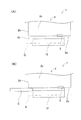
図8を参照して第3実施形態に係る携帯型磁気カードリーダ1について説明する。なお、図8(A)は、本発明の第3実施形態に係わるカード非挿入時における携帯型磁気カードリーダの正面図であり、図8(B)は、カード挿入時における携帯型磁気カードリーダの正面図である。
[Third Embodiment]
Next, a third embodiment will be described.
A portable magnetic card reader 1 according to the third embodiment will be described with reference to FIG. 8A is a front view of the portable magnetic card reader when the card is not inserted according to the third embodiment of the present invention, and FIG. 8B is a portable magnetic card reader when the card is inserted. FIG.

ばね部材15は、図8(A)に示すように、筐体2と対向壁13とを連結すると共に、対向壁13を読取側外壁部2bに向けて付勢する構成で設けられている。これにより、対向壁13とこれに連結した連結部11とが一体となって可動部となる。   As shown in FIG. 8A, the spring member 15 connects the casing 2 and the opposing wall 13 and is configured to bias the opposing wall 13 toward the reading side outer wall 2b. Thereby, the opposing wall 13 and the connection part 11 connected with this are united, and become a movable part.

また、図8(A)に示すように、上記カード非操作時には、対向壁13と読取側外壁部2aとが当接し、図8(B)に示すように、上記カード操作時には、対向壁13と読取側外壁部2aとが磁気カードCの介在により離間するようにカード挿通部10が構成されている。   As shown in FIG. 8A, when the card is not operated, the opposing wall 13 and the reading-side outer wall portion 2a come into contact with each other. As shown in FIG. The card insertion portion 10 is configured such that the reading side outer wall portion 2a is separated from the reading side outer wall portion 2a by the magnetic card C.

第1実施形態と同様に、図8(A)、(B)に示すように、非当接部分と当接部分として構成されており、且つカード非操作時における非当接部分と読取側外壁部2aとの間隔は、挿入側となるにつれて次第に広くなるように構成されている。さらに、対向壁13の先端部における非当接部分は、挿入側となるにつれて先端部と回動軸との距離が小さくなるように傾斜している。   As in the first embodiment, as shown in FIGS. 8A and 8B, the non-contact portion and the contact portion are configured as the non-contact portion and the contact-side outer wall when the card is not operated. The space | interval with the part 2a is comprised so that it may become wide gradually as it becomes an insertion side. Furthermore, the non-contact part in the front-end | tip part of the opposing wall 13 inclines so that the distance of a front-end | tip part and a rotating shaft may become small as it becomes an insertion side.

また、図1及び図4(A)に示すように、対向壁13の所定方向一部領域において先端部に当接部分が配置されており、磁気ヘッド3は、当接部分が配置される一部領域に覆われている。   Further, as shown in FIGS. 1 and 4A, a contact portion is disposed at the tip in a partial region of the opposing wall 13 in a predetermined direction, and the magnetic head 3 is provided with a contact portion. It is covered with a partial area.

(第3実施形態の主な効果)
図8(A)、(B)に示すような携帯型磁気カードリーダ1は、ばね部材15を筐体2内部に設けることで、筐体2外部の構造を第1実施形態よりもさらに簡易とすることができ
、磁気カードCを読み取る部分の小型化、軽量化を図ることができる。また、第1実施形態と同様に、磁気カードCの接触に伴う読み取り部分の塑性変形等を抑えられ、読み取り部分の変形に起因する読み取り不良を効果的に防止することができる。その上で、データ読取時に磁気ヘッド3に磁気カードCを押し付けながら正確なデータの読み取りができる。
(Main effects of the third embodiment)
The portable magnetic card reader 1 as shown in FIGS. 8A and 8B is provided with a spring member 15 inside the housing 2 so that the structure outside the housing 2 is further simplified than in the first embodiment. Thus, the portion for reading the magnetic card C can be reduced in size and weight. Further, similarly to the first embodiment, the plastic deformation or the like of the reading portion accompanying the contact of the magnetic card C can be suppressed, and reading defects due to the deformation of the reading portion can be effectively prevented. In addition, accurate data reading can be performed while pressing the magnetic card C against the magnetic head 3 during data reading.

図8(A)に示すように、カード非操作時に対向壁13が読取側外壁部2aに当接するように構成すれば、データ読み取り時により大きな力で磁気カードCを磁気ヘッド3に押し付けることができ、磁気カードCと磁気ヘッド3との接触を安定させることができる。   As shown in FIG. 8A, if the opposing wall 13 is in contact with the reading-side outer wall 2a when the card is not operated, the magnetic card C can be pressed against the magnetic head 3 with a greater force when reading data. The contact between the magnetic card C and the magnetic head 3 can be stabilized.

第1実施形態と同様に、当接部分と非当接部分とを備える所定の対向壁13を構成すれば、対向壁13によって付勢可能な構成を実現しつつ、磁気カードCのカード挿通部10への挿入のし易さを損なわないようにすることができる。さらに、カード挿入時に磁気カードCの引っ掛かり等の問題も生じにくくすることができる。   Similarly to the first embodiment, if a predetermined opposing wall 13 having an abutting portion and a non-abutting portion is configured, a card insertion portion of the magnetic card C can be realized while realizing a configuration that can be biased by the opposing wall 13. The ease of insertion into 10 can be prevented from being impaired. Further, problems such as the magnetic card C being caught when the card is inserted can be made difficult to occur.

また、磁気ヘッド3は当接部分が配置される一部領域に覆われている構成では、対向壁13の所定方向一部領域、すなわち先端部が対向壁13に接触する側で磁気ヘッド3を覆うことができるため、カード挿通部10への挿入のし易さを担保しつつ、磁気ヘッド3に対する磁気カードCの密着性を損なわないようにすることができる。   Further, in a configuration in which the magnetic head 3 is covered with a partial region where the contact portion is disposed, the magnetic head 3 is placed on a partial region of the opposing wall 13 in a predetermined direction, that is, on the side where the tip portion contacts the opposing wall 13. Since it can be covered, the adhesion of the magnetic card C to the magnetic head 3 can be prevented from being impaired while ensuring ease of insertion into the card insertion portion 10.

1…携帯型磁気カードリーダ
2…筐体
2a…読取側外壁部
3…磁気ヘッド
10…カード挿通部
11…連結部
13…対向壁
13a…第2所定部分(当接部分)
15、15a、15b…ばね部材(付勢手段)
21…第1所定部分(非当接部分)
C…磁気カード
DESCRIPTION OF SYMBOLS 1 ... Portable magnetic card reader 2 ... Housing 2a ... Reading side outer wall part 3 ... Magnetic head 10 ... Card insertion part 11 ... Connection part 13 ... Opposite wall 13a ... 2nd predetermined part (contact part)
15, 15a, 15b ... Spring member (biasing means)
21 ... 1st predetermined part (non-contact part)
C ... Magnetic card

Claims (6)

筐体の一方面に沿って移動操作される磁気カードを読み取る携帯型磁気カードリーダであって、
前記筐体の前記一方面側に設けられた読取側外壁部から前記磁気カードの移動経路に向けて露出して配置された磁気ヘッドと、
前記読取側外壁部との間を前記移動経路とするように当該読取用外壁部と対向して配置された対向壁と、
前記読取側外壁部側と前記対向壁とを連結する連結部と、
前記対向壁を前記読取側外壁部に向けて付勢する付勢手段と、
を備え、
前記対向壁は、前記連結部とは反対側を先端側とするように片持ち状に構成され、
前記磁気カードが前記読取側外壁部と前記対向壁との間に配置されないカード非操作時には、前記対向壁と前記読取側外壁部とが第1の距離で配置され、
前記磁気カードが前記読取側外壁部と前記対向壁との間を操作されるカード操作時には、前記付勢手段による付勢に抗して前記対向壁と前記読取側外壁部との間が前記第1の距離よりも大きい第2の距離に拡がるように退避すると共に、その移動操作される前記磁気カードが前記対向壁により前記読取側外壁部側に押圧されることを特徴とする携帯型磁気カードリーダ。
A portable magnetic card reader that reads a magnetic card that is moved and operated along one side of a housing,
A magnetic head disposed exposed from the reading-side outer wall provided on the one surface side of the housing toward the moving path of the magnetic card;
An opposing wall disposed to face the reading outer wall so as to be the movement path between the reading side outer wall and the reading side outer wall,
A connecting portion for connecting the reading side outer wall portion side and the facing wall;
Biasing means for biasing the opposing wall toward the reading-side outer wall;
With
The opposing wall is configured in a cantilever shape so that the side opposite to the connecting portion is the tip side,
At the time of card non-operation where the magnetic card is not disposed between the reading side outer wall portion and the facing wall, the facing wall and the reading side outer wall portion are disposed at a first distance,
During the card operation in which the magnetic card is operated between the reading-side outer wall portion and the opposing wall, the gap between the opposing wall and the reading-side outer wall portion is against the urging by the urging means. The portable magnetic card is retracted so as to extend to a second distance larger than the first distance, and the magnetic card to be moved is pressed toward the reading side outer wall by the opposing wall. leader.
前記カード非操作時には、前記対向壁と前記読取側外壁部とが当接し、
前記カード操作時には、前記対向壁と前記読取側外壁部とが前記磁気カードの介在により離間することを特徴とする請求項1に記載の携帯型磁気カードリーダ。
When the card is not operated, the facing wall and the reading side outer wall abut,
2. The portable magnetic card reader according to claim 1, wherein when the card is operated, the opposing wall and the reading-side outer wall portion are separated by interposition of the magnetic card.
前記連結部は、前記読取側外壁部の壁面から凸となる構成で配置され、
前記対向壁は、
基端側が前記読取側外壁部から離れた位置で前記連結部に取り付けられ、且つ所定の回動軸を中心として前記連結部に回動可能に保持され、
前記カード非操作時には、当該対向壁の先端部と前記読取側外壁部とが当接した第1回動位置となり、
前記カード操作時には、当該対向壁の前記先端部と前記読取側外壁部とが離間した第2回動位置となるように構成されていることを特徴とする請求項2に記載の携帯型磁気カードリーダ。
The connecting portion is arranged in a configuration that protrudes from the wall surface of the reading-side outer wall portion,
The opposing wall is
The base end side is attached to the connecting portion at a position away from the reading side outer wall portion, and is held rotatably on the connecting portion around a predetermined rotation axis,
When the card is not operated, the first rotation position where the tip of the opposing wall and the reading side outer wall abut,
3. The portable magnetic card according to claim 2, wherein when the card is operated, the distal end portion of the facing wall and the reading-side outer wall portion are in a second rotation position that is separated from each other. leader.
前記連結部は、前記読取側外壁部に沿って所定方向に続いており、
前記対向壁と前記読取側外壁部との間の移動経路は、前記所定方向の一方側が前記磁気カードの挿入側、他方側が前記磁気カードの取出側として構成されており、
前記対向壁の先端部は、前記所定方向の前記挿入側に配される第1所定部分が前記カード非操作時に前記読取側外壁部と当接しない非当接部分として構成され、前記所定方向の取出側に配される第2所定部分が前記カード非操作時に前記読取側外壁部と当接する当接部分として構成されており、且つ前記カード非操作時における前記非当接部分と前記読取側外壁部との間隔は、前記挿入側となるにつれて次第に広くなるように構成されていることを特徴とする請求項1から請求項3のいずれか一項に記載の携帯型磁気カードリーダ。
The connecting portion continues in a predetermined direction along the reading side outer wall portion,
The movement path between the opposing wall and the reading-side outer wall portion is configured such that one side of the predetermined direction is an insertion side of the magnetic card and the other side is an extraction side of the magnetic card,
The front end portion of the opposing wall is configured as a non-contact portion in which a first predetermined portion arranged on the insertion side in the predetermined direction does not contact the reading-side outer wall portion when the card is not operated, A second predetermined portion arranged on the take-out side is configured as a contact portion that contacts the reading side outer wall portion when the card is not operated, and the non-contact portion and the reading side outer wall when the card is not operated The portable magnetic card reader according to any one of claims 1 to 3, wherein an interval with a portion is configured to gradually become wider toward the insertion side.
前記対向壁の前記所定方向一部領域において前記先端部に前記当接部分が配置されており、
前記磁気ヘッドは、前記当接部分が配置される前記一部領域に覆われていることを特徴とする請求項4に記載の携帯型磁気カードリーダ。
The abutting portion is arranged at the tip in the partial region in the predetermined direction of the opposing wall;
The portable magnetic card reader according to claim 4, wherein the magnetic head is covered with the partial region where the contact portion is disposed.
前記対向壁の前記先端部における前記非当接部分は、前記挿入側となるにつれて前記先端部と前記回動軸との距離が小さくなるように傾斜していることを特徴とする請求項4又は請求項5に記載の携帯型磁気カードリーダ。   The non-contact portion at the tip portion of the opposing wall is inclined so that the distance between the tip portion and the rotation shaft becomes smaller toward the insertion side. The portable magnetic card reader according to claim 5.
JP2011052954A 2011-03-10 2011-03-10 Portable magnetic card reader Withdrawn JP2012190507A (en)

Priority Applications (1)

Application Number Priority Date Filing Date Title
JP2011052954A JP2012190507A (en) 2011-03-10 2011-03-10 Portable magnetic card reader

Applications Claiming Priority (1)

Application Number Priority Date Filing Date Title
JP2011052954A JP2012190507A (en) 2011-03-10 2011-03-10 Portable magnetic card reader

Publications (1)

Publication Number Publication Date
JP2012190507A true JP2012190507A (en) 2012-10-04

Family

ID=47083504

Family Applications (1)

Application Number Title Priority Date Filing Date
JP2011052954A Withdrawn JP2012190507A (en) 2011-03-10 2011-03-10 Portable magnetic card reader

Country Status (1)

Country Link
JP (1) JP2012190507A (en)

Similar Documents

Publication Publication Date Title
JP5179924B2 (en) Card reader shutter mechanism and card reader
JP4906523B2 (en) Card connector
EP1577826A2 (en) IC card reader
JP5021096B2 (en) Magnetic card reader
US9519846B2 (en) Card reader
JP2004185822A (en) Connector device for card
JP2012190507A (en) Portable magnetic card reader
JP5603564B2 (en) Information reader
US10282568B2 (en) Card reader
JP6941236B2 (en) Image reader
JP7279514B2 (en) media reader
JP4462002B2 (en) Optical disk device
JP2017220323A (en) Card connector and electronic device
JP6096073B2 (en) Magnetic head holding mechanism, card processing device
JP4888355B2 (en) Terminal holding apparatus and portable information reading terminal holding structure
US20020040931A1 (en) IC contact unit and IC card reader
JP4661956B2 (en) Disk device and printing device
TW410328B (en) Recording medium driving apparatus
JP2001250209A (en) Magnetic stripe reader device
JP2018116415A (en) Card reader
JP2005182302A (en) Card reader
JP2010113446A (en) Card connector
JP2011165604A (en) Card connector
JP2004362407A (en) Card slot mechanism
JP2013045323A (en) Information reading device and magnetic information reading device

Legal Events

Date Code Title Description
A300 Withdrawal of application because of no request for examination

Free format text: JAPANESE INTERMEDIATE CODE: A300

Effective date: 20140513