JP2012190451A - Electronic apparatus - Google Patents
Electronic apparatus Download PDFInfo
- Publication number
- JP2012190451A JP2012190451A JP2012038825A JP2012038825A JP2012190451A JP 2012190451 A JP2012190451 A JP 2012190451A JP 2012038825 A JP2012038825 A JP 2012038825A JP 2012038825 A JP2012038825 A JP 2012038825A JP 2012190451 A JP2012190451 A JP 2012190451A
- Authority
- JP
- Japan
- Prior art keywords
- touch panel
- bezel
- press
- housing
- seal member
- Prior art date
- Legal status (The legal status is an assumption and is not a legal conclusion. Google has not performed a legal analysis and makes no representation as to the accuracy of the status listed.)
- Granted
Links
Images


Classifications
-
- H—ELECTRICITY
- H05—ELECTRIC TECHNIQUES NOT OTHERWISE PROVIDED FOR
- H05K—PRINTED CIRCUITS; CASINGS OR CONSTRUCTIONAL DETAILS OF ELECTRIC APPARATUS; MANUFACTURE OF ASSEMBLAGES OF ELECTRICAL COMPONENTS
- H05K5/00—Casings, cabinets or drawers for electric apparatus
- H05K5/06—Hermetically-sealed casings
- H05K5/061—Hermetically-sealed casings sealed by a gasket held between a removable cover and a body, e.g. O-ring, packing
-
- G—PHYSICS
- G06—COMPUTING; CALCULATING OR COUNTING
- G06F—ELECTRIC DIGITAL DATA PROCESSING
- G06F1/00—Details not covered by groups G06F3/00 - G06F13/00 and G06F21/00
- G06F1/16—Constructional details or arrangements
- G06F1/1613—Constructional details or arrangements for portable computers
- G06F1/1633—Constructional details or arrangements of portable computers not specific to the type of enclosures covered by groups G06F1/1615 - G06F1/1626
- G06F1/1637—Details related to the display arrangement, including those related to the mounting of the display in the housing
-
- G—PHYSICS
- G06—COMPUTING; CALCULATING OR COUNTING
- G06F—ELECTRIC DIGITAL DATA PROCESSING
- G06F1/00—Details not covered by groups G06F3/00 - G06F13/00 and G06F21/00
- G06F1/16—Constructional details or arrangements
- G06F1/1613—Constructional details or arrangements for portable computers
- G06F1/1633—Constructional details or arrangements of portable computers not specific to the type of enclosures covered by groups G06F1/1615 - G06F1/1626
- G06F1/1656—Details related to functional adaptations of the enclosure, e.g. to provide protection against EMI, shock, water, or to host detachable peripherals like a mouse or removable expansions units like PCMCIA cards, or to provide access to internal components for maintenance or to removable storage supports like CDs or DVDs, or to mechanically mount accessories
-
- G—PHYSICS
- G06—COMPUTING; CALCULATING OR COUNTING
- G06F—ELECTRIC DIGITAL DATA PROCESSING
- G06F3/00—Input arrangements for transferring data to be processed into a form capable of being handled by the computer; Output arrangements for transferring data from processing unit to output unit, e.g. interface arrangements
- G06F3/01—Input arrangements or combined input and output arrangements for interaction between user and computer
- G06F3/016—Input arrangements with force or tactile feedback as computer generated output to the user
-
- H—ELECTRICITY
- H04—ELECTRIC COMMUNICATION TECHNIQUE
- H04M—TELEPHONIC COMMUNICATION
- H04M1/00—Substation equipment, e.g. for use by subscribers
- H04M1/02—Constructional features of telephone sets
- H04M1/18—Telephone sets specially adapted for use in ships, mines, or other places exposed to adverse environment
-
- H—ELECTRICITY
- H04—ELECTRIC COMMUNICATION TECHNIQUE
- H04M—TELEPHONIC COMMUNICATION
- H04M1/00—Substation equipment, e.g. for use by subscribers
- H04M1/02—Constructional features of telephone sets
- H04M1/0202—Portable telephone sets, e.g. cordless phones, mobile phones or bar type handsets
- H04M1/026—Details of the structure or mounting of specific components
- H04M1/0266—Details of the structure or mounting of specific components for a display module assembly
Abstract
Description
本発明は、タッチパネルを備える電子機器に関するものである。 The present invention relates to an electronic device including a touch panel.
現在、電子機器の入力装置として、タッチパネルやタッチパッドなどが広く採用されている。そのような入力装置において、操作者がタッチパネルやタッチパッドなどを操作した際に、タッチパネルやタッチパッドを振動させることにより、操作者の指先などに操作感をフィードバックするものが提案されている(例えば、特許文献1参照)。 Currently, touch panels and touch pads are widely used as input devices for electronic devices. In such an input device, when an operator operates a touch panel, a touch pad, or the like, a device that feeds back a feeling of operation to an operator's fingertip or the like by vibrating the touch panel or the touch pad has been proposed (for example, , See Patent Document 1).
図8は、特許文献1に記載の電子機器の分解斜視図である。図8に示すように、特許文献1に記載の電子機器(ディスプレイ装置)は、ディスプレイモニタ100、パネル固定用フレーム210、タッチパネル400、およびカバー500を備えている。この電子機器は、タッチパネル400等の各部品が、上記ディスプレイモニタ100に対して組付けられることにより構成されている。
FIG. 8 is an exploded perspective view of the electronic device described in Patent Document 1. As shown in FIG. 8, the electronic device (display device) described in Patent Document 1 includes a
特許文献1に記載の電子機器において、ディスプレイモニタ100は、液晶ディスプレイ(LCD)からなり、全体が矩形かつ扁平な形状を有している。ディスプレイモニタ100は、図示しない制御装置による制御に従って、例えばキーやボタン等のオブジェクトまたは各種の情報などを、その表示面に表示する。このディスプレイモニタ100の表示面上には、当該モニタ100とほぼ同じ大きさのタッチパネル400が位置するように組付けられる。
In the electronic device described in Patent Document 1, the
タッチパネル400は、例えば透明な樹脂板にマトリクス状のスイッチ回路が形成され、パネル表面が操作者の指先などにより接触されると、その接触位置に応じた検出信号を制御装置に出力するように構成されている。つまり、操作者は、タッチパネル400を通して映し出されるディスプレイモニタ100の表示に従って当該パネル400に対して操作を行うことにより、電子機器に対して当該表示に応じた各種情報を入力することができる。
The
この電子機器においては、図8に示すように、タッチパネル400の裏面側の対向する2辺に沿って、それぞれ圧電素子(ピエゾ素子)420が貼り付けられている。タッチパネル400が操作者による接触を検出すると、この電子機器は、制御装置から圧電素子420に駆動信号(電圧)を付与する。この駆動信号を受信すると、圧電素子420は伸縮するため、この電子機器は、タッチパネル400の操作面に対して振動を発生させることができる。すなわち、上記操作に伴って、タッチパネル400が振動することにより、操作者は操作感を得ることができるようになっている。
In this electronic apparatus, as shown in FIG. 8, piezoelectric elements (piezo elements) 420 are attached along two opposing sides on the back surface side of the
なお、この電子機器において、タッチパネル400は、パネル固定用フレーム210を介してディスプレイモニタ100に組付けられている。パネル固定用フレーム210は、ABS等の硬質の樹脂材料から形成されることにより全体が剛性を有した構成となっている。
In this electronic apparatus, the
図8に示すように、パネル固定用フレーム210には、タッチパネル400をその四隅において保持するホルダ220が組付けられる。図9は、4つのホルダ220のうち1つが、タッチパネル400の隅に取り付けられる様子を示す拡大図である。各ホルダ220には、タッチパネル400の角部を差込み可能なスリット状の差込み部360がそれぞれ形成されている。また、図8に示すように、パネル固定用フレーム210の周囲側面には、各側面それぞれの端部付近に、ホルダ220を固定するための固定孔320が設けられている。そして、図9に示すホルダ220に形成されたフック340aが、図8に示す各固定孔320に差し込まれることにより、各ホルダ220は、タッチパネル400をパネル固定用フレーム210に固定される。
As shown in FIG. 8,
このように、各ホルダ220にタッチパネル400の四隅がそれぞれ差込まれると、各ホルダ220は、タッチパネル400を四隅で外側から拘束するとともに、厚み方向の両側からも拘束した状態で保持する。したがって、特許文献1に記載の電子機器は、タッチパネル400が固定されるように配置することができる。
As described above, when the four corners of the
また、ホルダ220は、それぞれ、パネル固定用フレーム210よりも弾性係数の小さい材料から形成されており、例えばシリコン系の樹脂またはゴムにより一体成型されている。このように、ホルダ220は、タッチパネル400を安定的に保持する一方で、タッチパネル400が振動できるように弾性変形可能に構成されている。なお、タッチパネル400とディスプレイモニタ100との間には、タッチパネル400の厚み方向の変位を可能とする隙間が確保される。このため、圧電素子420が振動する際に、当該振動に伴うタッチパネル400の厚み方向の変位が可能となっている。
Each of the
したがって、特許文献1に記載の電子機器は、タッチパネル400を振動させる際に、その振動を大きく妨げることがないようになっているため、タッチパネル400の振動による操作感を良好に確保することができる。
Therefore, since the electronic device described in Patent Document 1 is configured not to greatly disturb the vibration when the
しかしながら、特許文献1に記載の電子機器は、例えば車載用ナビゲーションシステムのディスプレイ装置などを想定しており、電子機器そのものの防塵対策および防水対策は特に施されていない。例えば、図8に示す電子機器を組み立てると、タッチパネル400は、弾性材料のホルダ220の差込み部360に差し込まれた状態で、つまりホルダ220を介して、パネル固定用フレーム210に取り付けられる。これは、タッチパネル400をパネル固定用フレーム210に強固に固定してしまうと、圧電素子420が振動する際に、タッチパネル400が厚み方向に変位せず、タッチパネル400を良好に振動させることができなくなるためである。したがって、タッチパネル400とパネル固定用フレーム210との間には、隙間ができることになり、当該隙間から埃や水分が浸入することが多分に想定される。
However, the electronic device described in Patent Document 1 is assumed to be, for example, a display device of an in-vehicle navigation system, and no dust-proof measures and waterproof measures are taken for the electronic device itself. For example, when the electronic device shown in FIG. 8 is assembled, the
そこで、特許文献1に記載の電子機器において、防塵対策として、例えば、タッチパネル400とパネル固定用フレーム210との間に防塵用クッションなどの部材を挿入することが考えられる。しかし、このような防塵用クッションは、ある程度圧縮可能な材質を用いたとしても、圧縮後の厚さのぶんだけタッチパネルが振動する物理的なスペースを奪ってしまうことになる。したがって、このような構造においては、タッチパネルが振動する際の振幅を稼ぐことができないことになる。
Therefore, in the electronic device described in Patent Document 1, as a dust-proof measure, for example, a member such as a dust-proof cushion may be inserted between the
また、特許文献1に示されている電子機器に対して防水を施す場合、外部からの埃や水の浸入を防ぐために、例えば、タッチパネル400と当該タッチパネル400の周囲を覆う部材との間を防水テープで固着するという対策が考えられる。例えば図8に示したように、パネル固定用フレーム210を介してタッチパネル400とディスプレイモニタ100とを組み合わせたものに、さらにカバー500を装着する場合、カバー500とタッチパネル400とを防水テープで固着することが想定される。このようにすれば、カバー500とタッチパネル400との隙間を埋めることができるため、外部からの水の浸入を防ぐことが可能になる。
Further, when waterproofing the electronic device disclosed in Patent Document 1, in order to prevent entry of dust and water from the outside, for example, waterproofing is performed between the
しかしながら、このようにカバー500とタッチパネル400とを防水テープで固着してしまうと、タッチパネル400が振動する際の振幅を稼ぐことができなくなるとともに、タッチパネル400を振動させる際の振幅を抑制してしまうことになる。
However, if the
かかる事情に鑑みてなされた本発明の目的は、タッチパネルの振動を可能な限り減殺させずに防塵および防水対策を施した電子機器を提供することにある。 An object of the present invention made in view of such circumstances is to provide an electronic device that is dust-proofed and waterproofed without reducing the vibration of the touch panel as much as possible.
上記目的を達成する本発明に係る電子機器は、タッチパネルと、該タッチパネルを振動させる振動部と、前記タッチパネルに取り付けられた弾性シール部材と、前記タッチパネルの上面周縁部を覆うように筐体に装着されたベゼルと、を備え、前記弾性シール部材は、前記タッチパネルの側面全周に亘って固着されて、前記筐体の前記タッチパネルの取り付け開口部の壁面に、前記タッチパネルと一体に摺動可能に圧入される圧入部と、前記タッチパネルの周囲の少なくとも一部において前記ベゼルの装着部に延在して、前記ベゼルと前記支持部材との間に挟持される被挟持部と、を有する、ことを特徴とするものである。 An electronic device according to the present invention that achieves the above object is mounted on a housing so as to cover a touch panel, a vibration part that vibrates the touch panel, an elastic seal member that is attached to the touch panel, and an upper surface peripheral part of the touch panel. The elastic seal member is fixed over the entire side surface of the touch panel, and is slidable integrally with the touch panel on the wall surface of the mounting opening of the touch panel of the housing. A press-fitting portion that is press-fitted, and a sandwiched portion that extends to the mounting portion of the bezel in at least a part of the periphery of the touch panel and is sandwiched between the bezel and the support member. It is a feature.
さらに、上記目的を達成する本発明に係る電子機器は、タッチパネルと、該タッチパネルを振動させる振動部と、前記タッチパネルに取り付けられた弾性シール部材と、前記タッチパネルの上面周縁部を覆うように筐体に装着されたベゼルと、を備え、前記弾性シール部材は、前記タッチパネルの側面全周に亘って接触されて、前記筐体の前記タッチパネルの取り付け開口部の壁面に、前記タッチパネルと一体に摺動可能に圧入される圧入部と、前記タッチパネルの底面端部全周に亘って固着されて、前記タッチパネルを載置する受け部と、前記タッチパネルの周囲の少なくとも一部において前記ベゼルの装着部に延在して、前記ベゼルと前記支持部材との間に挟持される被挟持部と、を有する、ことを特徴とするものである。 Furthermore, an electronic device according to the present invention that achieves the above-described object includes a touch panel, a vibration unit that vibrates the touch panel, an elastic seal member that is attached to the touch panel, and a casing that covers a peripheral surface of the upper surface of the touch panel. The elastic seal member is in contact with the entire circumference of the side surface of the touch panel and slides integrally with the touch panel on the wall surface of the mounting opening of the touch panel of the housing. A press-fit part that can be press-fitted, a bottom part of the bottom surface of the touch panel, and a receiving part on which the touch panel is placed; and at least a part of the periphery of the touch panel that extends to the mounting part of the bezel. And a sandwiched portion that is sandwiched between the bezel and the support member.
本発明によれば、タッチパネルの振動を可能な限り減殺させずに、防塵性および防水性を向上させた電子機器を提供することが可能となる。 ADVANTAGE OF THE INVENTION According to this invention, it becomes possible to provide the electronic device which improved dustproof property and waterproofness, without reducing the vibration of a touchscreen as much as possible.
以下、本発明の一実施の形態について、図を参照して説明する。 Hereinafter, an embodiment of the present invention will be described with reference to the drawings.
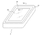
図1は、本発明の一実施の形態に係る電子機器の外観を示す斜視図である。図1に示す電子機器1は、外観上、筐体10と、タッチパネル20と、ベゼル30と、を備える。筐体10は、図示の例では一つの筐体として示しているが、上部筐体と下部筐体とが一体に組み合わされて構成される場合もある。この場合、上部筐体と下部筐体との間は、これらが一体に組み合わされた状態において、例えばゴム製のパッキンを介した密閉構造にする等して、適当な防塵および防水の措置が施されているものとする。筐体10は、ある程度の衝撃に耐えうる例えば樹脂により構成するのが好適である。
FIG. 1 is a perspective view showing an external appearance of an electronic apparatus according to an embodiment of the present invention. The electronic device 1 illustrated in FIG. 1 includes a
タッチパネル20は、後述するように表示部の表示面側に配置されて、表示部に表示されたオブジェクトに対する操作者の指やスタイラスペン等(以下、単に「接触物」と総称する)による接触を、対応するタッチパネル20のタッチ面において検出する。したがって、本実施の形態において、「タッチパネル」とは、表示部の前面に配置される部材、すなわち当該表示部とは別に設けられる部材を想定して説明する。また、タッチパネル20は、タッチ面に対する接触物の接触の位置を検出し、当該検出した接触の位置を制御部(図示せず)に通知する。
As will be described later, the
このタッチパネル20は、例えば抵抗膜方式、静電容量方式、光学式等の方式のものを用いることができる。なお、タッチパネル20が接触物による接触を検出する上で、接触物がタッチパネル20に物理的に触れることは必須ではない。例えば、タッチパネル20が光学式である場合は、タッチパネル20は当該タッチパネル20上の赤外線が接触物で遮られた位置を検出するため、接触物がタッチパネル20に触れることは不要である。
As this
ベゼル30は、タッチパネル20の上面の周縁部を覆うように、筐体10の上部に装着されている。つまり、本実施の形態において、ベゼル30は、筐体10を支持部材として、筐体10とタッチパネル20との間に跨るように筐体10に装着されている。そして、ベゼル30は、後述する防塵および防水用の弾性シール部材と協働して、筐体10とタッチパネル20との間の防塵および防水の機能を果たしている。ベゼル30は、例えば金属製、プラスチック製、樹脂製などとすることができ、薄型ながらもある程度の強度を有する素材で構成するのが好適である。
The
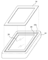
図2は、図1に示した電子機器1において、筐体10からベゼル30を取り外した状態を示す分解斜視図である。図2に示すように、ベゼル30は、筐体10の上部に段差状に成形された装着部10aに嵌め込まれるように構成されている。また、タッチパネル20の周囲には、防塵および防水用の弾性シール部材40が取り付けられている。ベゼル30は、弾性シール部材40およびタッチパネル20の周縁部を覆うことによって、弾性シール部材40およびタッチパネル20の周縁が外部から見えないようにしている。
FIG. 2 is an exploded perspective view showing a state in which the
図3は、図2に示したベゼル30を取り外した後、さらに筐体10からタッチパネル20および弾性シール部材40を一体に取り外した状態を示す分解斜視図である。弾性シール部材40は、例えばシリコンゴムからなり、タッチパネル20に固着されて、筐体10の取り付け開口部10bに圧入される。
FIG. 3 is an exploded perspective view illustrating a state in which the
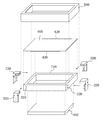
タッチパネル20は、その少なくとも四隅において支持子50を介して表示部60の表示面側に位置するように四点支持される。支持子50は、弾性シール部材40よりも硬度の高いシリコンゴムなどの弾性体とするのが好適である。支持子50は、その一端面がタッチパネル20の下面に接着され、他端面は、筐体10の底部や筐体10に固定された固定部、あるいは表示部60の上面の表示領域以外の領域に接着される。なお、タッチパネル20の支持点数は、四点支持に限らず、タッチパネル20の大きさに応じて、六点支持等、適宜設定することができる。本実施の形態においては、タッチパネル20が四個の支持子50を介して表示部60の上面に四点支持される場合を例示している。
The
表示部60は、例えば操作者が入力の操作に用いる押しボタンスイッチ等の各種のオブジェクトを画像で表示する。このオブジェクトは、タッチパネル20のタッチ面上において接触すべき領域を操作者に示唆する画像である。この表示部60は、例えば、液晶表示パネル(LCD)や有機EL表示パネル等を用いて構成される。
The
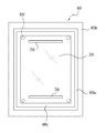
図4は、図3に示した弾性シール部材40からタッチパネル20を取り外した状態を一部切り欠いて示す分解斜視図である。また、図5は、図3に示した弾性シール部材40を固着したタッチパネル20を裏面から見た平面図である。タッチパネル20の裏面には、対向する二辺の近傍で、ベゼル30により覆われる部分にそれぞれ振動部を構成する圧電素子70が接着されている。圧電素子70は、例えば長さ方向に伸縮するもので、対応するタッチパネル20の辺に沿って、例えば両面テープまたは接着剤などにより接着される。そして、圧電素子70は、図示しない制御部から電圧が印加されると、その長手方向に伸縮してタッチパネル20を圧電素子70の長手方向に平行な方向に湾曲させる。これにより、圧電素子70は、印加電圧に応じた振動パターンでタッチパネル20を振動させて、タッチパネル20のタッチ面に接触している接触物に対して触感を呈示する。
FIG. 4 is an exploded perspective view showing a state where the
弾性シール部材40は、タッチパネル20の周囲に亘って取り付けられている。この弾性シール部材40は、タッチパネル20の側面全周に亘って固着されて、筐体10の取り付け開口部10bに圧入される。また、弾性シール部材40は、取り付け開口部10bの壁面10cに側圧により圧接される圧入部40aを有している。圧入部40aは、開口部10bの壁面10cに圧接される部分が、例えば断面半円状の突状に形成されて、タッチパネル20の湾曲振動に従って壁面10c(図3参照)を摺動可能に構成されている。
The
また、弾性シール部材40は、タッチパネル20の全周に亘ってベゼル30の筐体10への装着部10aに延在して、ベゼル30と筐体10との間に挟持される被挟持部40bを有する。さらに、弾性シール部材40は、タッチパネル20の下面縁部に固着される受け部40cを有する。なお、図4および図5は、受け部40cが、タッチパネル20の下面縁部の全周に亘って設けられている場合を例示しているが、この受け部40cは、部分的に設けてもよい。
The
弾性シール部材40は、タッチパネル20と一体成型によりタッチパネル20に取り付けられるか、あるいは、圧入部40aにおいて防水両面テープや接着剤による接着などによりタッチパネル20に取り付けられる。
The
タッチパネル20は、例えば、裏面に圧電素子70が固着され、かつ周囲に弾性シール部材40が取り付けられた状態で、弾性シール部材40の圧入部40aを縮めながら、図3に示した筐体10の取り付け開口部10bに嵌め込まれる。これにより、弾性シール部材40の圧入部40aが、筐体10の取り付け開口部10bに圧入されて、圧入部40aが取り付け開口部10bの壁面10cに側圧により圧接される。その後、ベゼル30が筐体10の装着部10aに装着されて、ベゼル30の装着部10aに延在する被挟持部40bが、ベゼル30と筐体10との間に挟持される。
The
図6は、図1のVI−VI線の拡大断面図である。図6に示すように、タッチパネル20は、その側面全周に設けられた弾性シール部材40の圧入部40aを介して、筐体10の取り付け開口部10bの壁面10cに側圧により圧接される。これにより、タッチパネル20と筐体10との間の防塵および防水効果が得られる。
FIG. 6 is an enlarged cross-sectional view taken along line VI-VI in FIG. As shown in FIG. 6, the
また、弾性シール部材40は、全周に亘って設けられた被挟持部40bが、ベゼル30の装着部10aにおいて、ベゼル30と筐体10との間に挟持される。これにより、防塵および防水効果をさらに高めることができるとともに、タッチパネル20の湾曲振動の振幅を可能な限り抑制せずに、圧入部40aを、タッチパネル20の湾曲振動に正確に追従させて、開口部10bの壁面10c上で摺動させることができる。つまり、被挟持部40bをベゼル30と筐体10との間に挟持して固定することにより、圧入部40aが開口部10bの壁面10c上で摺動変位した際に、圧入部40aと被挟持部40bとの連結部分に、圧入部40aを元の状態(位置)に戻そうとする弾性力(復元力)が作用することになる。これにより、圧入部40aは、タッチパネル20の湾曲振動に正確に追従して、開口部10bの壁面10cを摺動することになる。
In addition, the
なお、被挟持部40bをベゼル30と筐体10との間に挟持する場合、好ましくは、ベゼル30と被挟持部40bとの間、および、筐体10と被挟持部40bとの間を防水用両面テープ等により接着する、あるいは、被挟持部40bをベゼル30および筐体10により圧縮した状態で挟持する。これにより、防塵および防水効果をさらに高めることができる。
In the case where the sandwiched
このように、本実施の形態に係る電子機器1によれば、圧電素子70によりタッチパネル20を湾曲振動させる構成において、タッチパネル20の振動を可能な限り減殺させずに、防塵性および防水性を向上させることが可能となる。
As described above, according to the electronic device 1 according to the present embodiment, in the configuration in which the
なお、本発明は、上記実施の形態にのみ限定されるものではなく、幾多の変形または変更が可能である。例えば、上記実施の形態において、タッチパネル20は、圧電素子70が振動すると、圧電素子70の長さ方向と平行な辺が、他の辺よりも大きく湾曲変位する。したがって、弾性シール部材40の圧入部40aは、タッチパネル20の湾曲変位の大きい辺における側圧が、他の辺における側圧よりも小さくなるように構成して、タッチパネル20がよりスムーズに湾曲変位できるように構成することもできる。
In addition, this invention is not limited only to the said embodiment, Many deformation | transformation or a change is possible. For example, in the above-described embodiment, when the
また、タッチパネル20の湾曲変位の小さい辺では、当該辺に対応する圧入部40aの摺動変位も小さいので、当該辺に対応する被挟持部40bを省略することも可能である。この場合、当該辺に対応する圧入部40aは、側圧を比較的大きくして、防塵および防水機能をさらに高めるようにすることが好ましい。
Further, since the sliding displacement of the press-
さらに、図7に図6と同様の拡大断面図を示すように、被挟持部40bには、適宜の複数箇所に孔40dを形成し、ベゼル30には、孔40dを貫通する突起30aを形成して、突起30aを孔40dに貫通させて、被挟持部40bをベゼル30の装着部10aにおいて、ベゼル30と筐体10との間に挟持することもできる。このように構成すれば、被挟持部40bを、ベゼル30と筐体10との間に位置ずれを生じることなく保持することができるので、長期間に亘ってタッチパネル20の安定した湾曲変位が可能となる。
Further, as shown in FIG. 7 which is an enlarged cross-sectional view similar to FIG. 6, the sandwiched
また、弾性シール部材40の受け部40cは、圧入部40aのタッチパネル20に対する固着が充分であれば、省略することも可能である。さらに、タッチパネル20は、支持子50による支持を省略して、弾性シール部材40により筐体10の取り付け開口部10bに湾曲変位可能に支持するようにしてもよい。
The receiving
さらに、上記実施の形態では、タッチパネル20の周囲に亘って圧入部40aを固着した場合について説明したが、タッチパネル20の周囲に亘って圧入部40aが接触した状態で、タッチパネル20の底面端部全周に亘って受け部40cを固着するようにしてもよい。さらには、タッチパネル20が圧入部40aおよび受け部40cの双方に固着するようにしてもよい。
Further, in the above embodiment, the case where the press-
また、上記実施の形態では、タッチパネル20およびベゼル30の支持部材が筐体10である場合について説明したが、表示部60の図示しないホルダ等、筐体10に直接あるいは間接的に固定される部材であってもよく、本発明における筐体はこれらの部材を含むものを意味するものである。
Moreover, although the said embodiment demonstrated the case where the supporting member of the
また、上述した実施の形態においては、タッチパネル20の裏側に配置した表示部60にオブジェクトを表示してタッチパネル20が操作者の接触を検出する態様について説明した。しかしながら、本発明はこのような態様に限定されるものではなく、例えば表示部60を有さずに、タッチパネル20のタッチ面上にオブジェクトがインクなどにより直接印刷されているような態様を想定することもできる。
Moreover, in embodiment mentioned above, the aspect which displays an object on the
また、上記実施の形態では、タッチパネル20を用いて、当該タッチパネル20のタッチ面に対する接触を検出した。すなわち、上記実施の形態において、「タッチパネル20」は、いわゆるタッチセンサのような部材を想定して説明した。しかしながら、本発明による電子機器に用いるタッチパネルは、操作者の指やスタイラスペンなどの接触物により接触されるものであれば任意のものとすることができる。
In the above embodiment, the
例えば、本発明による電子機器に用いるタッチパネルは、タッチ面に対する接触物の接触の位置を検出しない(つまりセンシング機能を有さない)、単なる「パネル」のような部材とすることもできる。また、接触位置のセンシング機能の有無に関わらず、例えば、タッチパネルに対する押圧を検出する押圧検出部をさらに設け、該押圧検出部が検出する押圧に基づいて、タッチパネルに対する接触がなされたものと判定して、振動部を駆動してタッチパネルを振動させることができる。 For example, the touch panel used in the electronic device according to the present invention may be a member such as a simple “panel” that does not detect the position of contact of the contact object with the touch surface (that is, has no sensing function). Further, regardless of the presence / absence of the sensing function of the touch position, for example, a press detection unit that detects a press on the touch panel is further provided, and it is determined that the touch is made on the touch panel based on the press detected by the press detection unit. Then, the touch panel can be vibrated by driving the vibration unit.
このような押圧検出部は、タッチパネルのタッチ面に対する押圧を検出するもので、例えば、押圧に応じて物理的または電気的な特性(歪み、抵抗、電圧等)が変化する歪みゲージセンサや圧電素子等を任意の個数用いて構成することができる。また、振動部を圧電素子とした場合には、当該圧電素子を押圧検出部としても用いることができる。このような構成を採用して、押圧によるタッチパネルの歪みを検出することにより、当該歪みからタッチパネルに対する押圧を算出するなどの構成を想定することができる。 Such a pressure detection unit detects a pressure on the touch surface of the touch panel. For example, a strain gauge sensor or a piezoelectric element whose physical or electrical characteristics (distortion, resistance, voltage, etc.) change according to the pressure. Etc. can be configured using an arbitrary number. Further, when the vibration unit is a piezoelectric element, the piezoelectric element can also be used as a press detection unit. By adopting such a configuration and detecting the distortion of the touch panel due to the press, it is possible to assume a configuration in which the pressure on the touch panel is calculated from the distortion.
例えば、押圧検出部が圧電素子等を用いて構成された場合、押圧検出部の圧電素子は、タッチパネルのタッチ面に対する押圧に係る荷重(力)の大きさ(または、荷重(力)の大きさが変化する速さ(加速度))に応じて、電気的な特性である電圧の大きさ(電圧値)が変化する。この場合、押圧検出部は、この電圧の大きさ(電圧値(以下、単にデータと称する))を制御部に通知することができる。制御部は、押圧検出部がデータを制御部に通知することにより、または、制御部が押圧検出部の圧電素子に係るデータを検出することにより、当該データを取得する。つまり、制御部は、タッチパネルのタッチ面に対する押圧に基づくデータを取得する。すなわち、制御部は、押圧検出部から押圧に基づくデータを取得する。そして、制御部は、押圧に基づくデータが所定の基準を満たした場合に、接触がなされたものと判定し、所定の振動を発生することができる。ここで、上記所定の基準は、表現したい押しボタンスイッチの押圧時の荷重特性に応じて適宜設定することができる。 For example, when the pressure detection unit is configured using a piezoelectric element or the like, the piezoelectric element of the pressure detection unit is a load (force) magnitude (or magnitude of the load (force) related to the pressure on the touch surface of the touch panel. The voltage magnitude (voltage value), which is an electrical characteristic, changes according to the speed (acceleration) at which the voltage changes. In this case, the pressure detection unit can notify the control unit of the magnitude of the voltage (voltage value (hereinafter simply referred to as data)). The control unit acquires the data when the press detection unit notifies the control unit of the data, or when the control unit detects data related to the piezoelectric element of the press detection unit. That is, a control part acquires the data based on the press with respect to the touch surface of a touchscreen. That is, a control part acquires the data based on a press from a press detection part. Then, when the data based on the press satisfies a predetermined standard, the control unit can determine that contact has been made and generate a predetermined vibration. Here, the predetermined reference can be set as appropriate according to the load characteristic when the push button switch is to be expressed.
さらに、このような押圧検出部は、タッチパネルにおける接触検出方式に応じて構成することができる。例えば、抵抗膜方式の場合には、接触面積の大きさに応じた抵抗の大きさを、タッチパネルのタッチ面に対する押圧の荷重(力)に対応付けることにより、歪みゲージセンサや圧電素子等を用いることなく構成することができる。あるいは、静電容量方式の場合には、静電容量の大きさを、タッチパネルのタッチ面に対する押圧の荷重(力)に対応付けることにより、歪みゲージセンサや圧電素子等を用いることなく構成することができる。 Furthermore, such a press detection part can be comprised according to the contact detection system in a touch panel. For example, in the case of the resistance film method, a strain gauge sensor, a piezoelectric element, or the like is used by associating the magnitude of the resistance corresponding to the size of the contact area with the pressing load (force) on the touch surface of the touch panel. It can be configured without. Alternatively, in the case of the capacitance method, the capacitance can be configured without using a strain gauge sensor or a piezoelectric element by associating the size of the capacitance with a load (force) of pressing against the touch surface of the touch panel. it can.
また、振動部は、任意の個数の圧電振動子を用いて構成したり、タッチパネルの全面に透明圧電素子を設けて構成したり、偏心モータを駆動信号の1周期で1回転させるようにして構成したり、することもできる。さらに、押圧検出部および振動部は、圧電素子を用いて構成する場合は、圧電素子を共用して押圧検出部兼振動部を構成することもできる。圧電素子は、圧力が加わると電圧を発生し、電圧が加えられると変形するためである。 Further, the vibration unit is configured by using an arbitrary number of piezoelectric vibrators, is configured by providing a transparent piezoelectric element on the entire surface of the touch panel, or configured to rotate the eccentric motor once in one cycle of the drive signal. You can also do it. Furthermore, when the pressure detection unit and the vibration unit are configured using a piezoelectric element, the pressure detection unit and the vibration unit may be configured by sharing the piezoelectric element. This is because the piezoelectric element generates a voltage when pressure is applied and deforms when the voltage is applied.
また、上述したように、振動部は、押圧検出部も兼ねる圧電素子の電圧の大きさ(電圧値(データ))が所定の基準を満たした際に、当該圧電素子を駆動することにより振動を発生するようにもできる。ここで、圧電素子の電圧の大きさ(電圧値(データ))が所定の基準を満たした際とは、電圧値(データ)が所定の基準値に達した際であってもよいし、電圧値(データ)が所定の基準値を超えた際でもよいし、所定の基準値と等しい電圧値(データ)が検出された際でもよい。 Further, as described above, when the magnitude (voltage value (data)) of the voltage of the piezoelectric element that also serves as the pressure detection unit satisfies a predetermined standard, the vibration unit drives the piezoelectric element to generate vibration. It can also be generated. Here, when the voltage level (voltage value (data)) of the piezoelectric element satisfies a predetermined reference, the voltage value (data) may reach a predetermined reference value, It may be when the value (data) exceeds a predetermined reference value or when a voltage value (data) equal to the predetermined reference value is detected.
なお、振動部は、タッチパネルに圧電素子を配設することにより、タッチパネルを直接的に振動させるように構成してもよいし、振動モータ(偏心モータ)などに基づいて電子機器を振動させることにより、タッチパネルを間接的に振動させるように構成してもよい。 The vibration unit may be configured to directly vibrate the touch panel by disposing a piezoelectric element on the touch panel, or by vibrating the electronic device based on a vibration motor (eccentric motor) or the like. The touch panel may be configured to vibrate indirectly.
また、上述した実施形態においては、タッチパネル20を表示部60の表示面側に重ねて配置した構成について説明した。しかしながら、本発明による電子機器は、このような構成に限られるものではなく、タッチパネル20と表示部60とを離間した構成にすることもできる。しかしながら、タッチパネルを表示部60の表示面側に重ねて配置した構成とする方が、表示される画像と、操作入力が検出される領域および発生する振動との対応関係を、操作者に容易に認識させることができる。
In the above-described embodiment, the configuration in which the
上述した実施の形態の説明において、表示部60およびタッチパネル20は、表示部と接触検出部との両機能を共通の基板に持たせる等により、一体化した装置によって構成されるようにしてもよい。このように表示部と接触検出部との両機能を一体化した装置の一例としては、液晶パネルが有するマトリクス状配列の画素電極群に、フォトダイオード等の複数の光電変換素子を規則的に混在させたものを挙げることができる。この装置は、液晶パネル構造によって画像を表示する一方で、パネル表面の所望位置をタッチ入力するペンの先端で液晶表示用のバックライトの光を反射させ、この反射光を周辺の光電変換素子で受光することによって、タッチ位置を検出することができる。
In the description of the above-described embodiment, the
1 電子機器
10 筐体
10a 装着部
10b 取り付け開口部
10c 壁面
20 タッチパネル
30 ベゼル
40 弾性シール部材
40a 圧入部
40b 被挟持部
40c 受け部
50 支持子
60 表示部
70 圧電素子
DESCRIPTION OF SYMBOLS 1
Claims (2)
該タッチパネルを振動させる振動部と、
前記タッチパネルに取り付けられた弾性シール部材と、
前記タッチパネルの上面周縁部を覆うように筐体に装着されたベゼルと、を備え、
前記弾性シール部材は、
前記タッチパネルの側面全周に亘って固着されて、前記筐体の前記タッチパネルの取り付け開口部の壁面に、前記タッチパネルと一体に摺動可能に圧入される圧入部と、
前記タッチパネルの周囲の少なくとも一部において前記ベゼルの装着部に延在して、前記ベゼルと前記支持部材との間に挟持される被挟持部と、を有する、
ことを特徴とする電子機器。 A touch panel;
A vibrating section for vibrating the touch panel;
An elastic seal member attached to the touch panel;
A bezel attached to the housing so as to cover the peripheral edge of the upper surface of the touch panel,
The elastic seal member is
A press-fit portion that is fixed over the entire circumference of the side surface of the touch panel and is press-fitted to the wall surface of the attachment opening of the touch panel of the casing so as to be slidable integrally with the touch panel.
Extending to the mounting portion of the bezel in at least a part of the periphery of the touch panel, and a sandwiched portion sandwiched between the bezel and the support member,
An electronic device characterized by that.
該タッチパネルを振動させる振動部と、
前記タッチパネルに取り付けられた弾性シール部材と、
前記タッチパネルの上面周縁部を覆うように筐体に装着されたベゼルと、を備え、
前記弾性シール部材は、
前記タッチパネルの側面全周に亘って接触されて、前記筐体の前記タッチパネルの取り付け開口部の壁面に、前記タッチパネルと一体に摺動可能に圧入される圧入部と、
前記タッチパネルの底面端部全周に亘って固着されて、前記タッチパネルを載置する受け部と、
前記タッチパネルの周囲の少なくとも一部において前記ベゼルの装着部に延在して、前記ベゼルと前記支持部材との間に挟持される被挟持部と、を有する、
ことを特徴とする電子機器。 A touch panel;
A vibrating section for vibrating the touch panel;
An elastic seal member attached to the touch panel;
A bezel attached to the housing so as to cover the peripheral edge of the upper surface of the touch panel,
The elastic seal member is
A press-fit portion that is contacted over the entire circumference of the side surface of the touch panel and is press-fitted to the wall surface of the mounting opening of the touch panel of the housing so as to be slidable integrally with the touch panel;
A receiving part that is fixed over the entire bottom edge of the touch panel and places the touch panel;
Extending to the mounting portion of the bezel in at least a part of the periphery of the touch panel, and a sandwiched portion sandwiched between the bezel and the support member,
An electronic device characterized by that.
Priority Applications (1)
| Application Number | Priority Date | Filing Date | Title |
|---|---|---|---|
| JP2012038825A JP5809081B2 (en) | 2011-02-24 | 2012-02-24 | Electronics |
Applications Claiming Priority (3)
| Application Number | Priority Date | Filing Date | Title |
|---|---|---|---|
| JP2011038377 | 2011-02-24 | ||
| JP2011038377 | 2011-02-24 | ||
| JP2012038825A JP5809081B2 (en) | 2011-02-24 | 2012-02-24 | Electronics |
Publications (2)
| Publication Number | Publication Date |
|---|---|
| JP2012190451A true JP2012190451A (en) | 2012-10-04 |
| JP5809081B2 JP5809081B2 (en) | 2015-11-10 |
Family
ID=46720553
Family Applications (1)
| Application Number | Title | Priority Date | Filing Date |
|---|---|---|---|
| JP2012038825A Expired - Fee Related JP5809081B2 (en) | 2011-02-24 | 2012-02-24 | Electronics |
Country Status (2)
| Country | Link |
|---|---|
| JP (1) | JP5809081B2 (en) |
| WO (1) | WO2012114763A1 (en) |
Cited By (2)
| Publication number | Priority date | Publication date | Assignee | Title |
|---|---|---|---|---|
| JP2014186653A (en) * | 2013-03-25 | 2014-10-02 | Kyocera Corp | Input device and electronic apparatus |
| JP2015043826A (en) * | 2013-08-27 | 2015-03-12 | 日立アプライアンス株式会社 | Washing machine |
Families Citing this family (8)
| Publication number | Priority date | Publication date | Assignee | Title |
|---|---|---|---|---|
| JP5850168B2 (en) * | 2012-09-17 | 2016-02-03 | 株式会社村田製作所 | Touch input device |
| WO2014046279A1 (en) * | 2012-09-24 | 2014-03-27 | 京セラ株式会社 | Vibration device and electronic instrument |
| JP5674895B1 (en) | 2013-10-29 | 2015-02-25 | 京セラ株式会社 | Electronics |
| JP5925874B2 (en) * | 2014-12-22 | 2016-05-25 | 京セラ株式会社 | Electronics |
| CN112083817A (en) * | 2019-06-14 | 2020-12-15 | 致伸科技股份有限公司 | Touch pad module and electronic computer with same |
| EP4055467A4 (en) * | 2019-11-07 | 2023-08-02 | Fresenius Medical Care Deutschland GmbH | Seal for touch screen module, touch screen module, monitor and method for assembling monitor |
| CN112739095B (en) * | 2020-12-23 | 2022-05-20 | Oppo广东移动通信有限公司 | Electronic device with a detachable cover |
| CN116071993A (en) * | 2021-11-03 | 2023-05-05 | 荣耀终端有限公司 | Foldable terminal |
Citations (2)
| Publication number | Priority date | Publication date | Assignee | Title |
|---|---|---|---|---|
| JP2005228161A (en) * | 2004-02-13 | 2005-08-25 | Fujitsu Component Ltd | Flat board vibration device and switch using the same |
| JP2009105610A (en) * | 2007-10-23 | 2009-05-14 | Casio Hitachi Mobile Communications Co Ltd | Waterproof structure and electronic apparatus |
Family Cites Families (3)
| Publication number | Priority date | Publication date | Assignee | Title |
|---|---|---|---|---|
| JP2000223858A (en) * | 1999-02-03 | 2000-08-11 | Casio Comput Co Ltd | Small-size electronic apparatus |
| US6897852B2 (en) * | 2002-03-28 | 2005-05-24 | Symbol Technologies, Inc. | Information input display device |
| JP2005209868A (en) * | 2004-01-22 | 2005-08-04 | Casio Comput Co Ltd | Electronic apparatus |
-
2012
- 2012-02-23 WO PCT/JP2012/001251 patent/WO2012114763A1/en active Application Filing
- 2012-02-24 JP JP2012038825A patent/JP5809081B2/en not_active Expired - Fee Related
Patent Citations (2)
| Publication number | Priority date | Publication date | Assignee | Title |
|---|---|---|---|---|
| JP2005228161A (en) * | 2004-02-13 | 2005-08-25 | Fujitsu Component Ltd | Flat board vibration device and switch using the same |
| JP2009105610A (en) * | 2007-10-23 | 2009-05-14 | Casio Hitachi Mobile Communications Co Ltd | Waterproof structure and electronic apparatus |
Cited By (2)
| Publication number | Priority date | Publication date | Assignee | Title |
|---|---|---|---|---|
| JP2014186653A (en) * | 2013-03-25 | 2014-10-02 | Kyocera Corp | Input device and electronic apparatus |
| JP2015043826A (en) * | 2013-08-27 | 2015-03-12 | 日立アプライアンス株式会社 | Washing machine |
Also Published As
| Publication number | Publication date |
|---|---|
| WO2012114763A1 (en) | 2012-08-30 |
| JP5809081B2 (en) | 2015-11-10 |
Similar Documents
| Publication | Publication Date | Title |
|---|---|---|
| JP5809081B2 (en) | Electronics | |
| JP5919025B2 (en) | Electronics | |
| JP5618867B2 (en) | Electronics | |
| WO2012114761A1 (en) | Electronic device | |
| JP2012190452A (en) | Electronic device | |
| JP2012190450A (en) | Electronic device | |
| JP5809080B2 (en) | Electronics | |
| JP5638634B2 (en) | Electronics | |
| JP2012173955A (en) | Electronic apparatus | |
| JP5586787B2 (en) | Electronics | |
| JP5611078B2 (en) | Electronics | |
| JP5767995B2 (en) | Electronics | |
| JP5805571B2 (en) | Electronics | |
| JP5653249B2 (en) | Electronics | |
| JP5777552B2 (en) | Electronics | |
| JP5719196B2 (en) | Electronics | |
| JP5530026B2 (en) | Electronics | |
| JP2012173896A (en) | Electronic apparatus | |
| JP2012185815A (en) | Electronic device | |
| JP5496373B2 (en) | Electronics | |
| JP5715862B2 (en) | Electronics | |
| JP5731227B2 (en) | Electronics | |
| JP5606954B2 (en) | Electronics | |
| JP5921811B2 (en) | Electronics | |
| WO2012140878A1 (en) | Electronic device |
Legal Events
| Date | Code | Title | Description |
|---|---|---|---|
| A621 | Written request for application examination |
Free format text: JAPANESE INTERMEDIATE CODE: A621 Effective date: 20140514 |
|
| A977 | Report on retrieval |
Free format text: JAPANESE INTERMEDIATE CODE: A971007 Effective date: 20150218 |
|
| A131 | Notification of reasons for refusal |
Free format text: JAPANESE INTERMEDIATE CODE: A131 Effective date: 20150224 |
|
| A521 | Request for written amendment filed |
Free format text: JAPANESE INTERMEDIATE CODE: A523 Effective date: 20150423 |
|
| TRDD | Decision of grant or rejection written | ||
| A01 | Written decision to grant a patent or to grant a registration (utility model) |
Free format text: JAPANESE INTERMEDIATE CODE: A01 Effective date: 20150901 |
|
| A61 | First payment of annual fees (during grant procedure) |
Free format text: JAPANESE INTERMEDIATE CODE: A61 Effective date: 20150910 |
|
| R150 | Certificate of patent or registration of utility model |
Ref document number: 5809081 Country of ref document: JP Free format text: JAPANESE INTERMEDIATE CODE: R150 |
|
| LAPS | Cancellation because of no payment of annual fees |