JP2012189479A - Shape measuring device - Google Patents
Shape measuring device Download PDFInfo
- Publication number
- JP2012189479A JP2012189479A JP2011054011A JP2011054011A JP2012189479A JP 2012189479 A JP2012189479 A JP 2012189479A JP 2011054011 A JP2011054011 A JP 2011054011A JP 2011054011 A JP2011054011 A JP 2011054011A JP 2012189479 A JP2012189479 A JP 2012189479A
- Authority
- JP
- Japan
- Prior art keywords
- target object
- measurement target
- lattice
- light source
- imaging
- Prior art date
- Legal status (The legal status is an assumption and is not a legal conclusion. Google has not performed a legal analysis and makes no representation as to the accuracy of the status listed.)
- Granted
Links
- 239000000758 substrate Substances 0.000 claims abstract description 58
- 238000004458 analytical method Methods 0.000 claims abstract description 40
- 230000003287 optical effect Effects 0.000 claims abstract description 36
- 238000005259 measurement Methods 0.000 claims description 191
- 238000003384 imaging method Methods 0.000 claims description 98
- 238000009792 diffusion process Methods 0.000 claims 1
- 238000000034 method Methods 0.000 description 55
- 230000010363 phase shift Effects 0.000 description 25
- 238000009826 distribution Methods 0.000 description 9
- 230000015572 biosynthetic process Effects 0.000 description 5
- 238000010586 diagram Methods 0.000 description 3
- 230000001678 irradiating effect Effects 0.000 description 3
- 230000002411 adverse Effects 0.000 description 2
- 238000006243 chemical reaction Methods 0.000 description 2
- 230000004075 alteration Effects 0.000 description 1
- 230000003247 decreasing effect Effects 0.000 description 1
- 239000005338 frosted glass Substances 0.000 description 1
- 239000005337 ground glass Substances 0.000 description 1
- 238000007689 inspection Methods 0.000 description 1
- 238000011835 investigation Methods 0.000 description 1
- 238000000691 measurement method Methods 0.000 description 1
- 238000002834 transmittance Methods 0.000 description 1
Images


Abstract
Description
本発明は、計測対象物体の形状を高速かつ高精度に計測する形状計測装置に関するものである。 The present invention relates to a shape measuring apparatus that measures the shape of a measurement target object at high speed and with high accuracy.
従来、物体や人体等の計測対象物体の形状を非接触かつ3次元的に計測する方法として、位相シフト法を用いた方法がある。位相シフト法は、位相を変化させながら格子画像や干渉縞画像を1台の撮影装置で順次撮影し、これら位相を変化させた複数枚の格子画像や干渉縞画像に基づいて格子の位相分布を求めるものである。 Conventionally, there is a method using a phase shift method as a method for non-contact and three-dimensionally measuring the shape of a measurement target object such as an object or a human body. In the phase shift method, a lattice image and an interference fringe image are sequentially photographed by a single photographing device while changing the phase, and the phase distribution of the lattice is calculated based on a plurality of lattice images and interference fringe images whose phases are changed. It is what you want.
これまでに、位相シフト法を用いた様々な方法が提案されてきた。例えば、特許文献1は、カメラを用いた形状計測装置において、カメラまたはプロジェクタのレンズ収差の影響を受けない高精度な形状計測を行うことを目的としており、格子が描かれた基準平板の画像からカメラまたはプロジェクタのレンズ中心座標を算出するのではなく、基準面に固定された2次元格子から、カメラの画素毎の視線が通る光路と、プロジェクタから投影される光の光路とをそれぞれ全て求めて、それら光路の交点として空間座標を算出する形状計測方法および装置について記載されている。
So far, various methods using the phase shift method have been proposed. For example,
しかしながら、特許文献1に記載の方法では、位相シフトを行うために格子基板を移動機構上に設けて格子基板を機械的に移動させるが、この移動機構は、例えばピエゾステージ等の非常に高価なものである。
また、格子の位相シフトを高速に行うことは困難であり、例えば高速で移動する物体の形状を計測することができない点に課題を残していた。
However, in the method described in
In addition, it is difficult to perform phase shift of the grating at high speed, and there remains a problem in that the shape of an object moving at high speed cannot be measured, for example.
そこで、本発明の目的は、計測対象物体の形状を高速かつ高精度に計測する方法を提供することにある。 Therefore, an object of the present invention is to provide a method for measuring the shape of an object to be measured at high speed and with high accuracy.
発明者らは、上記課題を解決する方途について鋭意検討した。その結果、図1に示すように、基板2の表面2a上に、複数の発光ダイオード(Light Emitting Diode,LED)3を一列に並べて配置した発光装置(光源)1を用意し、LED3を順次点灯させることにより、計測対象物体上に投影される格子の位相を高速にシフトできることを見出した(以下、上記方法を「光ステッピング法」と称する)。
The inventors diligently studied how to solve the above problems. As a result, as shown in FIG. 1, a light emitting device (light source) 1 in which a plurality of light emitting diodes (LEDs) 3 are arranged in a line on a
図2に、上記光源1を備える形状計測装置の一例を示す。この形状計測装置100は、光源用基板2と、該光源用基板2の表面上に配置された複数の格子投影用LED3とからなる格子投影用光源1と、1次元格子が描かれた格子面を含む、光源用基板2に平行に配置された格子プレート4とを有する格子投影部10と、1次元格子が投影された計測対象物体21を撮像する撮像部11と、撮影された画像に対して位相解析処理を施して、計測対象物体21の形状を求める解析制御装置12とを備える。この形状計測装置100を用いて、格子投影部10により格子プレート4の格子面に描かれた1次元格子が計測対象物体21に投影され、光源1におけるLED3を順次点灯させることにより、投影された1次元格子の位相を高速にシフトさせることができる。
In FIG. 2, an example of a shape measuring apparatus provided with the
しかしながら、格子投影用光源1にLEDを用いる場合には、以下のような問題が生じる。すなわち、図3に概略的に示すように、形状計測装置100により形状計測を行う際には、三角測量法の原理に基づいて、計測対象物体21、格子投影部10および撮像部11が、それぞれ三角形の頂点を為すように配置される。その際、計測対象物体21の表面における所望の形状計測領域を撮影できるように、計測対象物体21を撮影部11の正面に配置し、従って、格子投影部10は、計測対象物体21から見て斜め方向に配置されるのが一般的である。
However, when an LED is used for the grid
ここで、格子投影用LED3の発光強度分布は、図4に示すように、格子投影用LED3の光軸近傍の領域に分布しており、計測対象物体21の撮影に有効な光が到達する領域(以下、「有効光到達領域」と称する)は、撮像部11の性能に依存するものの、格子投影用LED3から有効な光が到達する限界の位置を規定する線(以下、「有効光限界線」と称する)で挟まれた狭い領域となる。そのため、格子投影部10から見て、計測対象物体21が斜め方向に配置されると、格子投影用LED3から照射された光が計測対象物体21に十分に届かず、その結果、照射された光の使用効率が著しく低下する。その結果、計測対象物体21に投影される1次元格子、ひいては撮影された画像も暗くなり、計測誤差が増大してしまう。
Here, as shown in FIG. 4, the light emission intensity distribution of the
上記問題を回避するために、格子投影部10全体を計測対象物体21に向けると、格子投影部10の座標軸と撮像部11の座標軸とが異なってしまうため、撮影された画像に対して位相解析処理を施して計測対象物体21の形状を求める際に、座標変換を行う必要が生じる。その結果、解析処理が複雑になるとともに多くの時間を要することになり、高速な形状計測が妨げられてしまう。
In order to avoid the above problem, when the entire
そこで、格子投影部10と撮像部11の位置関係(両者の座標系が同一の状態)を固定した状態で、計測対象物体21を格子投影部10の正面に配置すると、撮像部11から見て、計測対象物体21は斜め前方に存在することになるため、今度は得られた画像データに対して回転処理を施す等の画像データの変換処理を行う必要が生じ、高速な形状計測を行うことができなくなる。
また、撮像部11は、計測対象物体21を斜め方向から撮影することになるため、形状を計測しようとする計測対象物体21上の領域を適切に撮影できない虞もある。
Therefore, when the
In addition, since the
このように、計測対象物体21の形状計測を行う際には、格子投影部10、撮像部11、および計測対象物体21の位置関係について制限があり、格子投影用光源1から照射された光を計測対象物体21上に有効に照射し、照射された光の使用効率を向上させる方途が希求されている。
As described above, when measuring the shape of the
そこで、発明者らは、上記制限の下で、LED3から照射光の使用効率を向上させる方途について鋭意検討した結果、光源用基板2上に複数の格子投影用LED3を配置し、該LED3の各々の光軸が、光源用基板2の法線に対して、計測対象物体21側に傾斜させて配置することが有効であることを見出し、本発明を完成させるに到った。
Thus, as a result of intensive investigations on how to improve the use efficiency of the irradiation light from the
ところで、計測対象物体21の3次元の画像データを取得する際、計測対象物体21の表面の3次元座標とともに、計測対象物体21の輝度および色相のデータを取得することが必要になる。そのため、計測対象物体21に所定の色の光を照射するための撮像用光源を設ける必要があるが、格子投影用光源11とは別に撮像用光源を設けると、装置の小型化が困難になる問題がある。そこで、発明者らは、鋭意検討した結果、格子投影部10が撮像用LEDを更に備えるように構成することが有効であることを見出し、本発明を完成させるに到った。
By the way, when acquiring the three-dimensional image data of the
すなわち、本発明の形状計測装置は、計測対象物体の形状を計測する装置であって、光源用基板と該光源用基板上に配置された複数の格子投影用発光ダイオードとからなる格子投影用光源と、1次元格子が描かれた格子面を含む、前記光源用基板に平行に配置された格子プレートとを有する格子投影部と、前記1次元格子が投影された前記計測対象物体を撮像する撮像部と、前記撮影された画像に対して位相解析処理を施して前記計測対象物体の形状を求める解析装置とを備え、前記複数の格子投影用発光ダイオードの各々の光軸が、前記光源用基板の法線に対して、前記計測対象物体側に傾斜していることを特徴とするものである。 That is, the shape measuring device of the present invention is a device for measuring the shape of an object to be measured, and includes a light source for lattice projection comprising a light source substrate and a plurality of light emitting diodes for lattice projection arranged on the light source substrate. A grid projection unit including a grid surface on which the one-dimensional grid is drawn and a grid plate arranged in parallel to the light source substrate; and imaging for imaging the measurement target object on which the one-dimensional grid is projected And an analysis device that performs a phase analysis process on the photographed image to obtain the shape of the measurement target object, and each of the optical axes of the plurality of grating projection light emitting diodes includes the light source substrate. It is characterized in that it is inclined toward the measurement object side with respect to the normal line.
また、本発明の形状計測装置において、前記光源用基板の表面が凹部または凸部を有し、前記複数の格子投影用発光ダイオードの各々は、前記凹部または前記凸部に配置されていることを特徴とするものである。 Moreover, in the shape measuring apparatus of the present invention, the surface of the light source substrate has a recess or a protrusion, and each of the plurality of grating projection light emitting diodes is disposed in the recess or the protrusion. It is a feature.
また、本発明の形状計測装置において、前記格子投影用光源が、前記計測対象物体を照明するための複数の撮像用発光ダイオードを更に備えることを特徴とするものである。 In the shape measuring apparatus of the present invention, the grid projection light source further includes a plurality of imaging light emitting diodes for illuminating the measurement target object.
また、本発明の形状計測装置において、前記撮像用発光ダイオードの各々の光軸が前記格子プレートを通過することを特徴とするものである。 In the shape measuring apparatus of the present invention, each optical axis of the imaging light emitting diode passes through the lattice plate.
また、本発明の形状計測装置において、前記複数の撮像用発光ダイオードと前記格子プレートとの間に光拡散板を更に備えることを特徴とするものである。 In the shape measuring apparatus of the present invention, a light diffusing plate is further provided between the plurality of imaging light emitting diodes and the grating plate.
また、本発明の形状計測装置において、前記複数の撮像用発光ダイオード間の間隔は、前記格子投影用発光ダイオードの間隔よりも小さいことが好ましい。 In the shape measuring apparatus of the present invention, it is preferable that an interval between the plurality of imaging light emitting diodes is smaller than an interval between the grating projection light emitting diodes.
本発明の発光装置は、基板と、該基板上に配置された複数の発光ダイオードとを有し、該複数の発光ダイオードの各々の光軸は、前記基板の法線に対して傾斜していることを特徴とするものである。 The light emitting device of the present invention includes a substrate and a plurality of light emitting diodes disposed on the substrate, and an optical axis of each of the plurality of light emitting diodes is inclined with respect to a normal line of the substrate. It is characterized by this.
また、本発明の発光装置において、前記基板の表面が凹部または凸部を有し、前記複数の発光ダイオードの各々は、前記凹部または前記凸部に配置されていることを特徴とするものである。 In the light emitting device of the present invention, the surface of the substrate has a concave portion or a convex portion, and each of the plurality of light emitting diodes is disposed in the concave portion or the convex portion. .
本発明によれば、4つ以上の光源を順次点灯させることにより位相シフトを高速に行うことができるため、計測対象物体の形状を高速かつ高精度に計測することができる。 According to the present invention, since the phase shift can be performed at high speed by sequentially turning on four or more light sources, the shape of the measurement target object can be measured at high speed and with high accuracy.
以下、図面を参照して、本発明の実施形態について説明する。
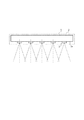
図5は、本発明による計測対象物体の形状計測装置を示す図である。この形状計測装置200は、光源用基板32と該光源用基板32上に配置された複数の格子投影用LED33とからなる格子投影用光源31と、1次元格子が描かれた格子面を含む、前記光源用基板32に平行に配置された格子プレート34とを有する格子投影部30と、1次元格子が投影された計測対象物体21を撮影する撮影部11と、撮影された画像に対して位相解析処理を施して、計測対象物体21の形状を求める解析装置12とを備える。ここで、複数の格子投影用LED33の各々の光軸が、光源用基板32の法線に対して、計測対象物体21側に傾斜していることが肝要である。以下、形状計測装置200の各構成について説明する。
Embodiments of the present invention will be described below with reference to the drawings.
FIG. 5 is a diagram illustrating a shape measuring apparatus for a measurement target object according to the present invention. The
格子投影部30は、計測対象物体21の形状を計測する際に、計測対象物体21に1次元格子を投影する。この格子投影用光源31に複数のLEDを用い、該LEDを順次点灯することにより、計測対象物体21上に投影された1次元格子の位相を高速にシフトさせることが可能になり、計測対象物体21の形状計測を高速に行うことができる。
上述のように、格子投影用LED33の光軸を、光源用基板32の法線に対して平行に向けて配置すると、格子投影用光源31から照射された光が、計測対象物体21に有効に届かない。そこで、本発明においては、複数の格子投影用LED33の各々の光軸を、計測対象物体21側に傾斜させるように構成する。これにより、格子投影用LED33から照射された光の使用効率を格段に向上させることができ、その結果、形状計測の精度も向上させることができる。
The
As described above, when the optical axis of the
光源用基板32上における複数の格子投影用LED33を、該LED33の光軸が光源用基板32の法線に対して、傾斜するように配置する方法は何ら限定されない。例えば、光源用基板32の表面に凹部または凸部を設け、該凹部または凸部に各LED33を配置することにより、各LED33を傾斜させて配置することができる。具体的には、図6に示すように、光源用基板32の表面にv字型の凹部32bを設けることにより、各LED33を傾斜させて配置することができる。また、図7に示すように、光源用基板32の表面にv字型の凸部32cを設けて格子投影用LED33を配置することができる。
The method of arranging the plurality of
光源用基板32の法線方向に対するLED33の光軸の傾斜角度は、LED33の有効光到達領域がLEDによって異なり、また、計測対象物体21との位置関係により異なるため、具体的な角度範囲は規定できないが、少なくともLED33全ての有効光到達領域を重ね合わせた領域中に、計測対象物体21が配置されるように設定する。
The angle of inclination of the optical axis of the
また、図6および7に例示した格子投影用LED33は、その全ての光軸が、光源用基板32の表面32aの法線に対して同じ角度で傾斜しているが、各LED33の光軸は、それぞれ異なる角度で傾斜させて配置しても良い。例えば、計測対象物体21から離れたLEDについては傾斜角度を大きくし、計測対象物体21に近いLEDについては傾斜角度を小さくすることができる。
6 and 7, all of the optical axes of the
格子投影用LED33の数は、計測対象物体21に照射される光の使用効率を向上させる点からは何ら限定されないが、形状計測の際に使用する位相解析手法に依存する。例えば、位相解析手法として後述する光ステッピング法を用いる場合には4個以上、また、全空間テーブル化手法に基づく位相解析手法の場合には3個以上あればよい。
The number of
また、格子投影用LED33の形状については、点光源ばかりでなく、線状光源とすることもできる。また、一般にLEDの出力は小さいため、複数の点光源を並べて線状の光源にし、出力を増やすようにすることもできる。
The shape of the
複数の格子投影用LED33の間隔については、計測対象物体21に照射される光の使用効率を向上させる点からは何ら限定されないが、形状計測の際に使用する位相解析手法により限定される場合がある。例えば、位相解析手法として後述する光ステッピング法を用いる場合には、X軸方向に等間隔に配置とする必要がある。一方、全空間テーブル化手法に基づく位相解析手法の場合には、必ずしも等間隔に配置する必要はない。
The interval between the plurality of
格子プレート34の格子面34aに描かれた1次元格子は、等間隔かつY軸方向に平行に並んだ直線からなる。格子投影用LED33から照射された光が格子プレート34を通過することにより、格子面34a上に描かれた1次元格子が計測対象物体21上に投影されるように構成されている。
The one-dimensional lattice drawn on the
撮像部11は、計測対象物体21、および格子投影部10により1次元格子が投影された計測対象物体21を撮像する。撮像部11としては、例えばCMOSカメラやCCDカメラを使用することができる。
The
解析制御装置12は、撮像部11により撮影された計測対象物体21の画像に対して位相解析処理を施すことにより、計測対象物体21の形状を求めるとともに、格子投影部10におけるLED3の点灯の切り換え制御や、撮像部11の撮影の制御を行う。この解析制御装置12としては、例えばパーソナルコンピュータ(PC)を用いることができる。
The
このような本発明による形状計測装置により、計測対象物体の形状を高速に計測することができる。
また、格子投影用LEDの光軸を、光源用基板の法線に対して計測対象物体側に傾斜させて配置したため、格子投影用LEDから照射された光を計測対象物体に有効に照射して、照射光の使用効率、ひいては形状計測の精度を向上させることができる。
With such a shape measuring apparatus according to the present invention, the shape of the object to be measured can be measured at high speed.
In addition, since the optical axis of the grid projection LED is arranged to be inclined toward the measurement target object with respect to the normal of the light source substrate, the light irradiated from the grid projection LED is effectively irradiated to the measurement target object. In addition, the use efficiency of irradiation light, and hence the accuracy of shape measurement can be improved.
以上の本発明の形状計測装置200に、撮像用LEDを更に設けることにより、計測対象物体21の形状計測とともに、計測対象物体21の3次元の画像データを取得するために必要となる、計測対象物体21の輝度および色相のデータを取得することが可能になる。
By providing an imaging LED in the
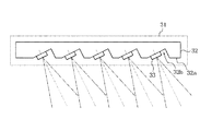
図8は、格子投影部40における格子投影用光源41に、複数の撮像用LED45を備える形状計測装置300を示している。この撮像用LED45は、計測対象物体21の3次元の画像データを取得するために必要となる、計測対象物体21の輝度および色相のデータを取得するために、計測対象物体21に所定の波長(色)の光を照射する。
FIG. 8 shows a
ここで、撮像用LED45は、格子投影用LED43とともに、光源用基板42上の計測対象物体21側に配置されている。これにより、格子投影用光源41がコンパクトになるとともに、撮像用LED45を格子投影用LED43の制御が容易になり、計測対象物体21の形状計測とともに3次元の画像データを取得するために必要となる、計測対象物体21の輝度および色相のデータを瞬時に取得することができるようになる。
Here, the
また、計測対象物体21に1次元格子を投影するための格子プレート44は、撮像用LED45の有効光到達領域に入らないように構成されている。
Further, the
計測対象物体21の形状計測を行う際には、撮像用LED45は全て消灯させた状態で、格子投影用LED43を順次点灯させるようにする。一方、計測対象物体21を撮像する際には、格子投影用LED43を消灯させた状態で、撮像用LED45の全てを同時に点灯させるようにする。
When the shape of the
撮像用LED45としては、格子投影用LED43と同様に、点光源だけでなく、線状光源とすることもできる。また、撮像用LED45の出力は小さいため、複数の点光源を並べて線状の光源にし、出力を増やすようにすることもできる。また、撮像用LED45が照射する光の波長は、用途に応じて適切に選択するようにする。
The
撮像用LED45の数は、計測対象物体21に照射される光の使用効率を向上させる点からは何ら限定されず、計測対象物体21を明瞭に撮影できればよい。
更に、複数の撮像用LED45の間隔についても特に限定されず、必要に応じて適切に設定すればよい。
The number of the
Further, the interval between the plurality of
なお、撮像用LED45の光軸は、格子投影用LED43の場合とは異なり、光源用基板42の法線に対して必ずしも傾斜させる必要はないが、計測対象物体21側に傾斜させて配置することにより、計測対象物体21をより明るく照明させて、より明瞭な画像を撮影することができる。
Note that the optical axis of the
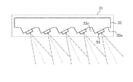
図9は、図8とは異なる構成を有する、撮像用LED45を備える形状計測装置を示している。この形状計測装置400と、図8に示した形状計測装置300との相違は、形状計測装置400における格子プレート44が、撮像用LED45の有効光到達領域に含まれることである。そのため、撮像用LED45から照射された光は、格子プレート44を通過し、従って、1次元格子が計測対象物体21に投影されることになる。しかし、後述する形状計測原理から明らかなように、撮像用LED45間の間隔を狭くして配置し、全ての撮像用LED45を同時に点灯させることにより、各LED45から投影された格子模様が重ね合わされるため、結果として計測対象物体21に投影された1次元格子を消すことができる。こうして、計測対象物体21には1次元格子が消された所定の色の光が照明されるため、計測対象物体21の3次元の画像データを取得するために必要となる、計測対象物体21の輝度および色相のデータを取得することができる。
FIG. 9 shows a shape measuring apparatus having an
また、形状計測装置400において、複数の撮像用LED45と格子プレート44との間に、すりガラス等の光拡散板を更に配置することにより、撮像用LED45を点灯させた際に計測対象物体21上に投影される1次元格子を更に目立たせないようにして、計測物体21を撮像することができる。この光拡散板は、格子プレート44を介した計測対象物体21上への1次元格子の投影に悪影響を与えないような適切な位置に配置する。
Further, in the
上記の形状計測装置400において、複数の撮像用LED45間の間隔は、小さければ小さいほど好ましい。この複数の撮像用LED45間の間隔は、単にLED45の間隔を狭めるだけでなく、LED面内において、複数の撮像用LED45の並ぶ向きをX軸に対して傾斜させることにより調整することもできる。
In the
なお、図9において、撮像用LED45は、格子投影用LED43よりも小さく描かれているが、これは、撮像用LED45の間隔が細かく設定されていることを意味するものであり、格子投影用LEDよりも寸法が小さいことを意味していないことに注意する。
In FIG. 9, the
こうして、撮像用LED45を設けることにより、所定の波長(色)の光を計測対象物体21に照射して、計測対象物体21の3次元の画像データを取得するために必要となる、計測対象物体21の輝度および色相のデータを瞬時に取得することができる。
Thus, by providing the
図10は、本発明による計測対象物体の形状計測装置を示す図である。この形状計測装置500は、光源用基板52と該光源用基板52上に配置された複数の格子投影用LED53とからなる格子投影用光源51と、1次元格子が描かれた格子面を含む、前記光源用基板52に平行に配置された格子プレート54と、前記光源用基板52上に配置された複数の撮像用LED55とを有する格子投影部50と、1次元格子が投影された計測対象物体21を撮影する撮影部11と、撮影された画像に対して位相解析処理を施して、計測対象物体21の形状を求める解析制御装置12とを備える。ここで、格子プレート54は、撮像用LED55の光軸が格子プレート54を通過しないように構成されている。以下、形状計測装置500の各構成について説明する。
FIG. 10 is a diagram illustrating a shape measuring apparatus for a measurement target object according to the present invention. The
格子投影部50は、計測対象物体21の形状を計測する際に、計測対象物体21に1次元格子を投影する。ここで、格子投影用LED53は、その光軸が光源用基板52の法線方向に対して平行となるように配置される。格子投影用光源51に複数のLEDを用い、該LEDを順次点灯することにより、計測対象物体21上に投影された1次元格子の位相を高速にシフトさせることが可能になり、計測対象物体21の形状計測を高速に行うことができる。
The
格子投影用LED53の数は、計測対象物体21に照射される光の使用効率を向上させる点からは何ら限定されないが、形状計測の際に使用する位相解析手法に依存する。例えば、位相解析手法として後述する光ステッピング法を用いる場合には4個以上、また、全空間テーブル化手法に基づく位相解析手法の場合には3個以上あればよい。
The number of
また、格子投影用LED53の形状については、点光源だけでなく、線状光源とすることもできる。また、LEDの出力は小さいため、複数の点光源を並べて線状の光源にし、出力を増やすようにすることもできる。
Further, the shape of the
複数の格子投影用LED53の間隔については、計測対象物体21に照射される光の使用効率を向上させる点からは何ら限定されないが、形状計測の際に使用する位相解析手法により限定される場合がある。例えば、位相解析手法として後述する光ステッピング法を用いる場合には、Y軸方向に等間隔に配置とする必要がある。一方、全空間テーブル化手法に基づく位相解析手法の場合には、必ずしも等間隔に配置する必要はない。
The interval between the plurality of
撮像用LED55は、計測対象物体21の3次元の画像データを取得するために必要となる、計測対象物体21の輝度および色相のデータを取得するために、計測対象物体21に所定の波長(色)の光を照射する。
The
ここで、撮像用LED55は、格子投影用LED53とともに、光源用基板52上の計測対象物体21側に配置されている。これにより、格子投影用光源51がコンパクトになるとともに、撮像用LED55および格子投影用LED53の制御が容易になり、計測対象物体21の形状計測とともに3次元の画像データを取得するために必要となる、計測対象物体21の輝度および色相のデータを瞬時に取得することができるようになる。
Here, the
計測対象物体21の形状計測を行う際には、撮像用LED55は全て消灯させた状態で、格子投影用LED53を順次点灯させるようにする。一方、計測対象物体21を撮像する際には、格子投影用LED53を消灯させた状態で、撮像用LED55の全てを同時に点灯させるようにする。
When measuring the shape of the
格子プレート54の格子面54aに描かれた1次元格子は、等間隔かつY軸方向に平行に並んだ直線からなる。格子投影用LED53から照射された光が格子プレート54を通過することにより、格子面54a上に描かれた1次元格子が計測対象物体21上に投影されるように構成されている。
The one-dimensional lattice drawn on the lattice surface 54a of the
撮像部11は、計測対象物体21、および格子投影部10により1次元格子が投影された計測対象物体21を撮像する。撮像部11としては、例えばCMOSカメラやCCDカメラを使用することができる。
The
解析制御装置12は、撮像部11により撮影された計測対象物体21の画像に対して位相解析処理を施すことにより、計測対象物体21の形状を求めるとともに、格子投影部50における格子投影用LED53の点灯の切り換え制御や、撮像部11の撮影の制御を行う。解析制御装置12としては、例えばパーソナルコンピュータ(PC)を用いることができる。
The
図11は、図10とは異なる構成を有する、撮像用LED55を備える形状計測装置を示している。この形状計測装置600と、図10に示した形状計測装置500との相違は、形状計測装置500における格子プレート54が、撮像用LED55の有効光到達領域に含まれることである。そのため、撮像用LED55から照射された光は、格子プレート54を通過し、従って、1次元格子が計測対象物体21に投影されることになる。
FIG. 11 shows a shape measuring apparatus having an
しかし、撮像用LED55間の間隔を狭めて配置し、全ての撮像用LED55を同時に点灯させることにより、各LED55から投影された格子模様が重ね合わされるため、結果として計測対象物体21に投影された1次元格子を消すことができる。こうして、計測対象物体21には1次元格子が消された所定の色の光が照明されるため、計測対象物体21の3次元の画像データを取得するために必要となる、計測対象物体21の輝度および色相のデータを取得することができる。
However, since the lattice patterns projected from the
また、形状計測装置600において、複数の撮像用LED55と格子プレート54との間に、すりガラス等の光拡散板を更に配置することにより、撮像用LED55を点灯させた際に計測対象物体21上に投影される1次元格子を更に目立たせないようにして、計測物体21を撮像することができる。この光拡散板は、格子プレート54を介した計測対象物体21上への1次元格子の投影に悪影響を与えないような適切な位置に配置する。
Further, in the
上記の形状計測装置600において、複数の撮像用LED55間の間隔は、小さければ小さいほど好ましい。この複数の撮像用LED55間の間隔は、単にLED55の間隔を狭めるだけでなく、LED面内において、複数の撮像用LED55の並ぶ向きをX軸に対して傾斜させることにより調整することもできる。
In the
なお、図11において、撮像用LED55は、格子投影用LED53よりも小さく描かれているが、これは、撮像用LED55の間隔が細かく設定されていることを意味するものであり、格子投影用LEDよりも寸法が小さいことを意味していないことに注意する。
In FIG. 11, the
こうして、撮像用LED55を設けることにより、計測対象物体21の形状計測とともに、所定の波長(色)の光を計測対象物体21に照射して、計測対象物体21の3次元の画像データを取得するために必要となる、計測対象物体21の輝度および色相のデータを瞬時に取得することができる。
In this way, by providing the
以上の本発明の形状計測装置を用いて、撮像部12により、1次元格子模様が投影された計測対象物体21を撮像し、撮影された画像に対して位相解析処理を施すことにより計測対象物体の形状を求めることができるが、位相解析処理の方法は限定されず、様々な方法を採用することができる。ここで、位相解析方法の例として、光ステッピング法、および全空間テーブル化手法について説明する。そのために、5つの格子投影用LED33を有する形状計測装置200を用いて形状計測を行う場合について説明するが、LED33の数が5以外の場合にも同様に計測することができる。
Using the shape measuring device of the present invention described above, the
[形状計測原理]
(基準面を用いない場合)
図12は、本発明による形状計測装置200を用いて、光ステッピング法により計測対象物体21の形状計測を行う原理を示す図である。この形状計測装置200は、光源用基板32と該光源用基板32上に等間隔かつ一列に並べられた5つの格子投影用LED33であるL-2、L-1、L0、L1およびL2からなる格子投影用光源31と、1次元格子が描かれた格子面34aを有する格子プレート34とを有する格子投影部30と、撮影部11とを備える。なお、図12において、解析制御装置12は省略されている。
ここで、5つの格子投影用LED33であるL-2、L-1、L0、L1およびL2における両端のLED間の中央位置(すなわち、L0の位置)を原点Oとし、5つのLEDを通る方向にX軸を、該X軸に直交する方向に、互いに直交するY軸およびZ軸をとる(以下、LED面からZ軸方向の位置を「高さ」と称する)。計測対象物体21は、Z軸方向に配置される。
なお、原点Oの位置は、LEDの数が5以外の場合にも上記と同様の方法、すなわち、4つ以上の光源における両端の光源間の中央位置として規定される。
[Shape measurement principle]
(When the reference plane is not used)
FIG. 12 is a diagram showing the principle of measuring the shape of the
Here, the center position (that is, the position of L 0 ) between the LEDs at both ends in the five grid projection LEDs 33 L −2 , L −1 , L 0 , L 1 and L 2 is the origin O, and the five The X axis is taken in the direction passing through the LED, and the Y axis and Z axis perpendicular to each other are taken in the direction perpendicular to the X axis (hereinafter, the position in the Z axis direction from the LED surface is referred to as “height”). The
Note that the position of the origin O is defined in the same manner as described above even when the number of LEDs is other than 5, that is, the center position between the light sources at both ends in four or more light sources.
LED間の間隔はlである。以下、5つのLEDであるL-2、L-1、L0、L1およびL2を含み、Z=0の面を「LED面」と呼ぶ。 The spacing between the LEDs is l. Hereinafter, a surface including five LEDs L −2 , L −1 , L 0 , L 1 and L 2 and having Z = 0 is referred to as an “LED surface”.
格子プレート34の格子面34aに描かれた1次元格子は、等間隔かつY軸方向に平行に並んだ直線からなる。格子投影用光源31から照射された光が格子プレート34を通過することにより、格子面34a上に描かれた1次元格子が計測対象物体21上に投影されるように構成されている。1次元格子を構成する直線の間隔はpであり、LED面と格子面34aとの間隔はdである。また、1次元格子を構成する直線間の中央位置のうち、Z軸からの距離が最短なものを原点Eとし、また、格子面34aとZ軸との交点をCとする。
The one-dimensional lattice drawn on the
以下の説明において、5つのLEDであるL-2、L-1、L0、L1およびL2の明るさ分布は、観測範囲内において、Z=一定のXおよびY軸方向に対して均一で等しいと仮定する。なお、均一でない場合は、その分布を係数として、考慮すればよいが、ここでは取り扱いを簡単にするため、均一と仮定する。 In the following description, the brightness distributions of five LEDs L −2 , L −1 , L 0 , L 1, and L 2 are uniform in the observation range with Z = constant X and Y axis directions. Are equal. If it is not uniform, the distribution may be considered as a coefficient, but here it is assumed to be uniform in order to simplify handling.
今、LEDであるLnのみを順次点灯し、1次元格子が計測対称物体21上に投影することを考える。このとき、Z=dにある1次元格子の透過率分布は余弦波状になっており、LEDであるLnにより照射された1次元格子の影の輝度分布は、以下の式で表される。
Now, only sequentially lighting the L n is LED, and considering that one-dimensional lattice is projected onto the measuring

まず、5つのLEDのうち、中央のL0の点灯により1次元格子が投影された計測対象物体21上の位置S(x,y,z)における輝度I0は、近似的に次式で表される。
First, Table of the five LED, the brightness I 0 at the position S on the
このとき、幾何学的関係より、 At this time, from the geometric relationship,
次に、LEDをL0からL1に切り換えると、G点の影は、Z=zの(x,y)面では、A点に投影される。このとき、点Sには1次元格子のF点の影が投影されている。
LEDであるL1による位置S(x,y,z)における輝度I1は,次のようにして求められる。
すなわち、LEDをL0からL1に切り替えたことにより、計測対象物体21に投影される1次元格子の位相(アンラッピングされた位相)は、以下の式(4)で与えられる量だけシフトする。
Next, when the LED is switched from L 0 to L 1 , the shadow of the point G is projected onto the point A in the (x, y) plane where Z = z. At this time, a shadow of point F of the one-dimensional lattice is projected onto point S.
The luminance I 1 at the position S (x, y, z) by the LED L 1 is obtained as follows.
That is, by switching the LED from L 0 to L 1 , the phase (unwrapped phase) of the one-dimensional grating projected onto the
同様に、LEDであるL0からLEDであるLnに切り替えることにより、式(2)に比べて位相がnΨだけシフトするため、位置S(x,y,z)における輝度Inは、次式となる。 Similarly, by switching from L 0 is a LED to L n is a LED, for shifting the phase only nΨ compared to equation (2), the luminance I n at position S (x, y, z), the following It becomes an expression.
![]()
こうして、Lnを点灯したときの、位置S(x,y,z)における輝度Inを求めることができた。
なお、計測対象物体21の反射率rを考慮する場合は、aおよびbに反射率rを掛ければよいが、ここでは説明を簡単化するために省略する。
![]()
Thus, when the lit L n, were able to determine the intensity I n at position S (x, y, z) .
Note that when the reflectance r of the
(位相シフト量Ψと高さzとの関係)
次に、高さzを求めるために、高さzと位相シフト量Ψまたは位相Φとの関係を求める。位相シフト量Ψが求められると、式(8)から、
(Relationship between phase shift amount Ψ and height z)
Next, in order to obtain the height z, the relationship between the height z and the phase shift amount Ψ or the phase Φ is obtained. When the phase shift amount Ψ is obtained, from the equation (8),
(位相Φと高さzとの関係)
また、式(12)から、
(Relationship between phase Φ and height z)
Also, from equation (12)
このように、位相シフト量Ψまたは位相Φを求めることができれば、式(14)または式(15)から、撮影部11の位置に関係なしに高さzを求めることができる。この位相シフト量Ψおよび位相Φを求める方法については後述する。
As described above, if the phase shift amount ψ or the phase Φ can be obtained, the height z can be obtained from the equation (14) or the equation (15) regardless of the position of the
また、xおよびy座標については、様々な方法、例えばフーリエ変換格子法により、X軸方向およびY軸方向の位相をそれぞれ求め、更に位相接続を行うことにより、各点におけるx座標およびy座標をそれぞれ得ることができる(例えば、特許第3281918号公報参照)。 For the x and y coordinates, the phase in the X-axis direction and the Y-axis direction are obtained by various methods, for example, the Fourier transform grid method, and further, phase connection is performed to obtain the x-coordinate and y-coordinate at each point. Each can be obtained (for example, refer to Japanese Patent No. 3281918).
なお、図12において、5つのLED以外の構成(X、YおよびZ軸も含む)の配置を全て固定した状態で、5つのLEDをZ=0の面内において原点Oを中心にしてX軸に対して傾けて配置することができる。つまり、5つのLEDは、X軸に対して平行である必要はない。この場合、上記の説明における5つのLED間の間隔lとしては、X軸方向(すなわち、1次元格子を構成する直線に垂直な方向)のLED間の間隔(すなわち、5つのLED間の間隔のX軸方向の成分)を用いる。LED間の間隔を物理的に狭めることは困難であるが、上記のように5つのLEDをX軸に対して傾けることにより、X軸方向のLED間の間隔を容易に狭めることができるようになる。 In FIG. 12, in the state where the arrangement of the configuration other than the five LEDs (including the X, Y, and Z axes) is all fixed, the five LEDs are arranged on the X axis around the origin O in the plane of Z = 0. It can be tilted with respect to. That is, the five LEDs do not need to be parallel to the X axis. In this case, the interval l between the five LEDs in the above description is the interval between the LEDs in the X-axis direction (that is, the direction perpendicular to the straight line constituting the one-dimensional lattice) (that is, the interval between the five LEDs). X-axis direction component) is used. Although it is difficult to physically reduce the interval between the LEDs, the interval between the LEDs in the X-axis direction can be easily reduced by tilting the five LEDs with respect to the X-axis as described above. Become.
また、図12において、5つのLED以外の構成(X、YおよびZ軸も含む)の配置を全て固定した状態で、Z=0の面内において、5つのLEDであるL―2,L―1,L0,L1,L2の各々を、Y軸方向の任意の位置に配置することもできる。つまり、5つのLEDであるL―2,L―1,L0,L1,L2は、X軸方向に等間隔に並んでいればよい。
Further, in FIG. 12, in the state where all the arrangements other than the five LEDs (including the X, Y, and Z axes) are fixed, five LEDs L- 2 , L- Each of L 1 , L 0 , L 1 , and L 2 can be arranged at an arbitrary position in the Y-axis direction. That is L-2 in five LED, L- 1, L 0,
こうして、計測対象物体21上の点Sの座標x、yおよびzを求めることができ、計測対象物体21の形状を求めることができる。
Thus, the coordinates x, y, and z of the point S on the
(基準面を用いる場合)
次いで、基準面を用いる場合の形状計測の原理について説明する。この形状計測方法は、4つ以上の光源からなる格子投影用光源と、1次元格子を有する格子面を含む、格子投影用光源に平行に配置された格子プレートと、撮影部であって、該撮影部のレンズの中心が格子投影用光源を含み格子プレートに平行な光源面上に配置された撮影部とを備える形状計測装置と、格子面に平行に配置された、基準面を含む基準平板とを用いて計測対象物体の形状を計測する方法であって、4つ以上の光源を順次点灯させて基準面に投影される1次元格子の位相をシフトさせながら、撮影部により基準面を撮影するステップと、計測対象物体を格子プレートと基準平板との間に配置し、4つ以上の光源を順次点灯させて計測対象物体に投影される1次元格子の位相をシフトさせながら、撮影部により計測対象物体を撮影するステップと、撮影された基準面の画像および計測対象物体の画像に対して位相解析処理を施して、計測対象物体の形状を求めるステップとを含む。ここで、4つ以上の光源は1次元格子を構成する直線に垂直な方向に等間隔に配置されており、光源面からの距離は、投影された1次元格子の、所定の位置での位相と、レンズ中心と所定の位置とを通る直線と基準面との交点における位相とに依存することを特徴とするものである。
以下、格子投影用光源を構成する光源の数が5つの場合を例に、本発明による別の形状計測方法の原理について説明するが、この場合についても5つの光源の場合に限定されないことに注意する。
(When using a reference surface)
Next, the principle of shape measurement when using a reference surface will be described. The shape measuring method includes a grating projection light source including four or more light sources, a grating plate including a grating surface having a one-dimensional grating, and arranged in parallel to the grating projection light source, and an imaging unit, A shape measuring device having a photographing unit disposed on a light source surface in which the center of the lens of the photographing unit includes a light source for lattice projection and is parallel to the lattice plate, and a reference plate including a reference surface disposed in parallel to the lattice surface In this method, the shape of the measurement target object is measured using four or more light sources that are sequentially turned on and the reference plane is imaged by the imaging unit while shifting the phase of the one-dimensional grating projected onto the reference surface. And a step of arranging the measurement target object between the grating plate and the reference plate, sequentially turning on four or more light sources and shifting the phase of the one-dimensional grating projected onto the measurement target object, Shooting objects to be measured A step that, by performing a phase analysis processing on the image of the image and the measurement object of the photographed reference plane, and determining the shape of the measurement object. Here, the four or more light sources are arranged at equal intervals in a direction perpendicular to the straight line constituting the one-dimensional grating, and the distance from the light source surface is the phase of the projected one-dimensional grating at a predetermined position. And the phase at the intersection of the straight line passing through the lens center and a predetermined position and the reference plane.
Hereinafter, the principle of another shape measuring method according to the present invention will be described by taking as an example the case where the number of light sources constituting the grid projection light source is five, but this case is not limited to the case of five light sources. To do.
図13は、図12に示した形状計測装置1に、LED面から距離zRだけ離れた位置に格子面34a(すなわちLED面)と平行な基準面13aを有する基準平板13を更に備える形状計測装置200である。ここで、撮影部11のレンズの中心Vは、X=vの位置に配置されている。すなわち、原点Oからレンズの中心VまでのX軸方向の距離はvである。計測対象物体21は、格子プレート34と基準平板13との間に配置される。
この形状計測装置200を用いて、まず、この基準面13aに1次元格子を投影し、その位相ΦR分布を記録し、次いで、基準面13aの前に計測対象物体21を配置し、該計測対象物体21上の点Sにおける、投影された1次元格子の位相ΦSを求める。これにより、撮影部11の各画素において、基準面13aと計測対象物体21上の点Sとの位相差(ΦS−ΦR)から、zまたは基準面13aからの高さhs=zR−zを求めることができる。以下に、その原理について説明する。
FIG. 13 shows the
Using this
今、撮影部11のある1画素Uが、計測対象物体21が格子プレート34と基準平板13との間に配置されていない場合には基準面13a上の点Rを、計測対象物体21が配置されている場合には該計測対象物体21上の点Sを見ているとする。計測対象物体21上に投影された1次元格子の、点Sでの位相をΦS、点Rでの位相をΦRとする。点Rと原点Oを結ぶ直線の格子面34aとの交点をQとする。このとき、位相ΦSとΦRは、それぞれ点Gと点Qにおける1次元格子の位相と同じであり、それらの位相差から次式の関係が得られる。
If one pixel U of the photographing
こうして、式(21)から、カメラの画素の基準面13aにおける位相ΦRおよび計測対象物体21上の点Sの位相ΦSから、点Sのz座標を求めることができる。また、等位相差(ΦS−ΦR)線は等高線となる。
Thus, from the equation (21), the z coordinate of the point S can be obtained from the phase Φ R on the
また、xおよびy座標については、基準面13a(すなわち、基準平板13)を用いない場合と同様に、例えばフーリエ変換格子法により、X軸方向およびY軸方向の位相をそれぞれ求め、更に位相接続を行うことにより、各点におけるx座標およびy座標をそれぞれ得ることができる。
なお、図12の場合と同様に、図13において、5つのLED以外の構成(X、YおよびZ軸も含む)の配置を全て固定した状態で、5つのLEDをZ=0の面内において原点Oを中心にしてX軸に対して傾けて配置することができる。つまり、5つのLEDは、X軸に対して平行である必要はない。この場合、上記の説明における5つのLED間の間隔lとしては、X軸方向(すなわち、1次元格子を構成する直線に垂直な方向)のLED間の間隔(すなわち、5つのLED間の間隔のX軸方向の成分)を用いる。LED間の間隔を物理的に狭めることは困難であるが、上記のように5つのLEDをX軸に対して傾けることにより、X軸方向のLED間の間隔を容易に狭めることができるようになる。
For the x and y coordinates, as in the case where the
As in the case of FIG. 12, in FIG. 13, in the state where all the arrangements other than the five LEDs (including the X, Y, and Z axes) are fixed, the five LEDs are arranged in the plane of Z = 0. It can be arranged to be inclined with respect to the X axis around the origin O. That is, the five LEDs do not need to be parallel to the X axis. In this case, the interval l between the five LEDs in the above description is the interval between the LEDs in the X-axis direction (that is, the direction perpendicular to the straight line constituting the one-dimensional lattice) (that is, the interval between the five LEDs). X-axis direction component) is used. Although it is difficult to physically reduce the interval between the LEDs, the interval between the LEDs in the X-axis direction can be easily reduced by tilting the five LEDs with respect to the X-axis as described above. Become.
また、図13において、5つのLED以外の構成(X、YおよびZ軸も含む)の配置を全て固定した状態で、Z=0の面内において、5つのLEDであるL―2,L―1,L0,L1,L2の各々を、Y軸方向の任意の位置に配置することもできる。つまり、5つのLEDであるL―2,L―1,L0,L1,L2は、X軸方向に等間隔に並んでいればよい。
Further, in FIG. 13, in a state where all the configurations other than the five LEDs (including the X, Y, and Z axes) are fixed, the five LEDs L- 2 , L- Each of L 1 , L 0 , L 1 , and L 2 can be arranged at an arbitrary position in the Y-axis direction. That is L-2 in five LED, L- 1, L 0,
こうして、計測対象物体21上の点Sの座標x、yおよびzを求めることができ、計測対象物体21の形状を求めることができる。
Thus, the coordinates x, y, and z of the point S on the
こうして、計測対象物体21上の点Sの座標x、yおよびzを求めることができ、計測対象物体21の形状を求めることができる。
Thus, the coordinates x, y, and z of the point S on the
(光ステッピング法による位相解析)
続いて、高さzを求めるために必要な、位相Φおよび位相シフト量Ψを求める方法について説明する。
上述のように、従来の位相シフト法が、図12または図13の格子を直接動かすことにより、位相2πを整数Nで割って、全ての位置にて位相を2π/Nずつシフトさせるのに対し、本発明の位相シフト法においては、5つのLEDを順次点灯および消灯させることにより、計測対象物体21に投影される1次元格子の位相を、式(14)で示される位相シフト量Ψにて等間隔に5回シフトさせる(初期位置を含めて)位相シフトを行う。この位相シフト量Ψは、通常、2πを5等分したものでない。また、式(14)から明らかなように、zの値によって位相シフト量Ψは異なる。
(Phase analysis by optical stepping method)
Next, a method for obtaining the phase Φ and the phase shift amount ψ necessary for obtaining the height z will be described.
As described above, the conventional phase shift method directly moves the grating of FIG. 12 or 13 to divide the phase 2π by the integer N and shift the phase by 2π / N at all positions. In the phase shift method of the present invention, by sequentially turning on and off the five LEDs, the phase of the one-dimensional grating projected onto the
図14は、余弦波状に輝度が変化する1次元格子の位相を、位相シフト量Ψにて等間隔に位相シフトさせたときの、標本点の輝度および位相のシフト量の関係を示す。光ステッピング法においては、I0における位相Φが求めるべき位相であり、Lnを切り替えて順次点灯させる毎に、Ψずつ位相シフトする。このとき、輝度は上述の式(13)で表され、全てのnについて書くと、 FIG. 14 shows the relationship between the luminance of the sample point and the phase shift amount when the phase of the one-dimensional grating whose luminance changes in a cosine wave shape is phase-shifted at equal intervals by the phase shift amount ψ. In the optical stepping method, the phase Φ at I 0 is the phase to be obtained, and the phase is shifted by Ψ each time L n is switched and sequentially turned on. At this time, the luminance is expressed by the above equation (13).
![]()
![]()
![]()
![]()
![]()
![]()
![]()
![]()
![]()
![]()
なお、式(13)を解くのに、式(22)〜(26)の5つの式を用いたが、未知数の数が4つであるため、この5つの式のうちの4つを用いれば、4つの未知数を求めることができるのは言うまでもない。
In order to solve equation (13), five equations of equations (22) to (26) were used, but since the number of unknowns is four, if four of these five equations are used, Needless to say, four unknowns can be obtained.
こうして、光ステッピング法により、計測対象物体21の形状を求めることができる。
Thus, the shape of the
(全空間テーブル化手法の適用)
上記の本発明の形状計測方法に、全空間テーブル化手法を適用することにより、計測対象物体21の形状計測を更に高速に行うことができる(例えば、特開2008−281491参照)。すなわち、図13に示すように、格子面34aに平行に配置された2次元格子が描かれた(または投影された)基準面13aを有する基準平板13を用意し、該基準平板13をZ軸方向に所定の微少量だけ移動させながら基準面13aを撮影し、撮影された画像に対して位相解析処理を施すことにより、撮影部11の各画素に対して、Ψ、Φおよび(ΦS−ΦR)とzとの関係をテーブルとして予め求めておく。こうして予め用意しておいた各画素に対するテーブルを参照することにより、各画素に対して得られた位相から高さzの値を求めることができる。
(Application of all space table method)
By applying the total space table formation method to the above-described shape measurement method of the present invention, the shape measurement of the
この全空間テーブル化手法においては、予め用意した画素毎のテーブルを参照するだけであり、三角測量などで用いる幾何学的計算をする必要がほとんどないため、計測対象物体21の形状を更に高速に求めることができる。
また、本発明による形状計測方法では、光源や格子面の配置等に、種々の拘束条件を設けたが、このような基準面13aを用いた位相解析により、5個のLEDの明るさ分布に多少のムラがある場合、点光源が完全な点ではなくて多少の面積がある場合、1次元格子やLEDの間隔が一定ではなく少々異なる場合、撮影部11のレンズの位置がLED面から少々外れる場合、平行に配置された各構成が平行から多少ずれる場合、および1次元格子の輝度分布が余弦波から多少ずれる場合のように、計測された位相と高さzとの関係が単調に変化して1対1の対応関係がありさえすれば、これらの誤差を打ち消し、計測対象物体21の形状を精度良く求めることができる。
In this total space table formation method, it is only necessary to refer to a table for each pixel prepared in advance, and there is almost no need to perform geometric calculation used in triangulation or the like, so that the shape of the
Further, in the shape measuring method according to the present invention, various constraint conditions are provided for the arrangement of the light source, the lattice plane, etc., but the brightness distribution of the five LEDs is obtained by the phase analysis using the
こうして、本発明による形状計測を用い、例えば上述の光ステッピング法や全空間テーブル化手法を用いて、計測対象物体の形状を高速かつ高精度に計測することができる。 In this way, using the shape measurement according to the present invention, the shape of the measurement target object can be measured at high speed and with high accuracy using, for example, the above-described optical stepping method or total space table formation method.
本発明によれば、複数のLEDを順次切り替えることにより、計測対象物体に投影された格子の位相を高速にシフトさせて、計測対象物体の形状を高速かつ高精度に計測できるため、電子部品の検査、人体計測、医療、および小型生物の立体観察や立体計測等に有用である。 According to the present invention, by sequentially switching a plurality of LEDs, the phase of the grating projected onto the measurement target object can be shifted at high speed, and the shape of the measurement target object can be measured with high speed and high accuracy. It is useful for inspection, human body measurement, medical care, and stereoscopic observation and stereoscopic measurement of small organisms.
1 光源
2 基板
2a 基板表面
3 LED
31,41,51 格子投影用光源
32,42,52 光源用基板
32a 光源用基板表面
3,33,43,53 L―2,L―1,L0,L1,L2 格子投影用LED
4,34,44,54 格子プレート
10,30,40,50 格子投影部
11 撮像部
12 解析制御装置
13 基準平板
13a 基準面
21 計測対象物体
32b 凹部
32c 凸部
34a 格子面
45,55 撮像用LED
100,200,300,400,500,600 形状計測装置
U 撮影装置の画素
V 撮影装置のレンズの中心
1
31, 41, 51 the lattice
4, 34, 44, 54
100, 200, 300, 400, 500, 600 Shape measuring device U Pixel of imaging device V Center of lens of imaging device
Claims (8)
光源用基板と該光源用基板上に配置された複数の格子投影用発光ダイオードとからなる格子投影用光源と、1次元格子が描かれた格子面を含む、前記光源用基板に平行に配置された格子プレートとを有する格子投影部と、
前記1次元格子が投影された前記計測対象物体を撮像する撮像部と、
前記撮影された画像に対して位相解析処理を施して前記計測対象物体の形状を求める解析装置と、
を備え、前記複数の格子投影用発光ダイオードの各々の光軸が、前記光源用基板の法線に対して、前記計測対象物体側に傾斜していることを特徴とする形状計測装置。 An apparatus for measuring the shape of an object to be measured,
A light source for lattice projection comprising a light source substrate and a plurality of light emitting diodes for lattice projection arranged on the light source substrate, and a lattice plane on which a one-dimensional lattice is drawn, are arranged in parallel to the light source substrate. A grid projection unit having a grid plate;
An imaging unit that images the measurement target object onto which the one-dimensional lattice is projected;
An analysis device for performing phase analysis processing on the captured image to obtain the shape of the measurement target object;
The shape measuring apparatus is characterized in that each of the plurality of grating projection light emitting diodes is inclined toward the measurement target object with respect to a normal line of the light source substrate.
該複数の発光ダイオードの各々の光軸は、前記基板の法線に対して傾斜していることを特徴とする発光装置。 A substrate and a plurality of light emitting diodes disposed on the substrate;
An optical axis of each of the plurality of light emitting diodes is inclined with respect to a normal line of the substrate.
Priority Applications (1)
| Application Number | Priority Date | Filing Date | Title |
|---|---|---|---|
| JP2011054011A JP5770495B2 (en) | 2011-03-11 | 2011-03-11 | Shape measuring device and lattice projection device |
Applications Claiming Priority (1)
| Application Number | Priority Date | Filing Date | Title |
|---|---|---|---|
| JP2011054011A JP5770495B2 (en) | 2011-03-11 | 2011-03-11 | Shape measuring device and lattice projection device |
Publications (2)
| Publication Number | Publication Date |
|---|---|
| JP2012189479A true JP2012189479A (en) | 2012-10-04 |
| JP5770495B2 JP5770495B2 (en) | 2015-08-26 |
Family
ID=47082813
Family Applications (1)
| Application Number | Title | Priority Date | Filing Date |
|---|---|---|---|
| JP2011054011A Expired - Fee Related JP5770495B2 (en) | 2011-03-11 | 2011-03-11 | Shape measuring device and lattice projection device |
Country Status (1)
| Country | Link |
|---|---|
| JP (1) | JP5770495B2 (en) |
Cited By (6)
| Publication number | Priority date | Publication date | Assignee | Title |
|---|---|---|---|---|
| US20140354797A1 (en) * | 2013-06-04 | 2014-12-04 | Samsung Electro-Mechanics Co., Ltd. | Calibration block for measuring warpage, warpage measuring apparatus using the same, and method thereof |
| JP5854544B1 (en) * | 2015-04-07 | 2016-02-09 | 藤垣 元治 | Shape measuring apparatus and shape measuring method |
| WO2017196084A1 (en) * | 2016-05-10 | 2017-11-16 | 엘지전자 주식회사 | Mobile robot and control method therefor |
| JP2018009883A (en) * | 2016-07-14 | 2018-01-18 | 株式会社Ihi | Distance measurement device and distance measurement method |
| WO2020027440A1 (en) * | 2018-08-01 | 2020-02-06 | 주식회사 뷰온 | Device and method for checking for surface defect, using image sensor |
| US11257232B2 (en) | 2017-05-08 | 2022-02-22 | University Of Fukui | Three-dimensional measurement method using feature amounts and device using the method |
Families Citing this family (1)
| Publication number | Priority date | Publication date | Assignee | Title |
|---|---|---|---|---|
| KR102257723B1 (en) * | 2019-11-19 | 2021-06-16 | 주식회사 앤에이치씨 | Scan apparatus |
Citations (8)
| Publication number | Priority date | Publication date | Assignee | Title |
|---|---|---|---|---|
| JPH09293999A (en) * | 1996-04-26 | 1997-11-11 | Matsushita Electric Ind Co Ltd | Image sensing device for part mounting equipment |
| US6122062A (en) * | 1999-05-03 | 2000-09-19 | Fanuc Robotics North America, Inc. | 3-D camera |
| JP2000292131A (en) * | 1999-04-07 | 2000-10-20 | Minolta Co Ltd | Three-dimensional information input camera |
| JP2003050112A (en) * | 2001-08-07 | 2003-02-21 | Minolta Co Ltd | Three-dimensional shape input device and projector |
| JP2004502168A (en) * | 2000-06-28 | 2004-01-22 | テラダイン・インコーポレーテッド | Illumination equipment for automatic optical inspection systems |
| JP2004053532A (en) * | 2002-07-23 | 2004-02-19 | Ricoh Co Ltd | Optical shape measuring device |
| JP2004226316A (en) * | 2003-01-24 | 2004-08-12 | Saki Corp:Kk | Scanning head and appearance inspection apparatus available for the same |
| JP2009244037A (en) * | 2008-03-31 | 2009-10-22 | Ushio Inc | Illuminating light source and pattern inspection device using the same |
-
2011
- 2011-03-11 JP JP2011054011A patent/JP5770495B2/en not_active Expired - Fee Related
Patent Citations (8)
| Publication number | Priority date | Publication date | Assignee | Title |
|---|---|---|---|---|
| JPH09293999A (en) * | 1996-04-26 | 1997-11-11 | Matsushita Electric Ind Co Ltd | Image sensing device for part mounting equipment |
| JP2000292131A (en) * | 1999-04-07 | 2000-10-20 | Minolta Co Ltd | Three-dimensional information input camera |
| US6122062A (en) * | 1999-05-03 | 2000-09-19 | Fanuc Robotics North America, Inc. | 3-D camera |
| JP2004502168A (en) * | 2000-06-28 | 2004-01-22 | テラダイン・インコーポレーテッド | Illumination equipment for automatic optical inspection systems |
| JP2003050112A (en) * | 2001-08-07 | 2003-02-21 | Minolta Co Ltd | Three-dimensional shape input device and projector |
| JP2004053532A (en) * | 2002-07-23 | 2004-02-19 | Ricoh Co Ltd | Optical shape measuring device |
| JP2004226316A (en) * | 2003-01-24 | 2004-08-12 | Saki Corp:Kk | Scanning head and appearance inspection apparatus available for the same |
| JP2009244037A (en) * | 2008-03-31 | 2009-10-22 | Ushio Inc | Illuminating light source and pattern inspection device using the same |
Cited By (10)
| Publication number | Priority date | Publication date | Assignee | Title |
|---|---|---|---|---|
| US20140354797A1 (en) * | 2013-06-04 | 2014-12-04 | Samsung Electro-Mechanics Co., Ltd. | Calibration block for measuring warpage, warpage measuring apparatus using the same, and method thereof |
| JP5854544B1 (en) * | 2015-04-07 | 2016-02-09 | 藤垣 元治 | Shape measuring apparatus and shape measuring method |
| WO2017196084A1 (en) * | 2016-05-10 | 2017-11-16 | 엘지전자 주식회사 | Mobile robot and control method therefor |
| US11231720B2 (en) | 2016-05-10 | 2022-01-25 | Lg Electronics Inc. | Moving robot and control method thereof |
| JP2018009883A (en) * | 2016-07-14 | 2018-01-18 | 株式会社Ihi | Distance measurement device and distance measurement method |
| US11257232B2 (en) | 2017-05-08 | 2022-02-22 | University Of Fukui | Three-dimensional measurement method using feature amounts and device using the method |
| WO2020027440A1 (en) * | 2018-08-01 | 2020-02-06 | 주식회사 뷰온 | Device and method for checking for surface defect, using image sensor |
| JP2021533344A (en) * | 2018-08-01 | 2021-12-02 | ビュー−オン リミテッド | Surface defect inspection device and inspection method using image sensor |
| JP7277996B2 (en) | 2018-08-01 | 2023-05-19 | ビュー-オン リミテッド | Surface defect inspection device and inspection method using image sensor |
| US11892414B2 (en) | 2018-08-01 | 2024-02-06 | View-On Ltd. | Device and method for checking for surface defect, using image sensor |
Also Published As
| Publication number | Publication date |
|---|---|
| JP5770495B2 (en) | 2015-08-26 |
Similar Documents
| Publication | Publication Date | Title |
|---|---|---|
| JP5770495B2 (en) | Shape measuring device and lattice projection device | |
| US10966614B2 (en) | Intraoral scanner | |
| US8854610B2 (en) | Apparatus and method for measuring a three-dimensional shape | |
| US6977732B2 (en) | Miniature three-dimensional contour scanner | |
| JP5648749B2 (en) | Shape measuring apparatus and shape measuring method | |
| CN107735645B (en) | Three-dimensional shape measuring device | |
| JP5443303B2 (en) | Appearance inspection apparatus and appearance inspection method | |
| KR20110119531A (en) | Shape measuring device and calibration method | |
| JP2013205407A (en) | Shape measurement device, shape measurement method, and calibration processing method in shape measurement device | |
| JP4077754B2 (en) | 3D shape measuring device | |
| CN105700280A (en) | Structured-Light Projector And Three-Dimensional Scanner Comprising Such A Projector | |
| EP3686550A1 (en) | Three-dimensional shape measuring apparatus | |
| JP7280774B2 (en) | Three-dimensional shape measuring device, three-dimensional shape measuring method, three-dimensional shape measuring program, computer-readable recording medium, and recorded equipment | |
| JP3975917B2 (en) | Position measurement system | |
| JP5657276B2 (en) | Shape measuring apparatus and shape measuring method | |
| JP6516453B2 (en) | Image measuring device and measuring device | |
| JP5956296B2 (en) | Shape measuring apparatus and shape measuring method | |
| JP5853284B2 (en) | Shape measuring apparatus and shape measuring method | |
| JP2012237613A (en) | Shape measuring device and shape measuring method | |
| JP5667891B2 (en) | Shape measurement method | |
| US20210131798A1 (en) | Structured light projection optical system for obtaining 3d data of object surface | |
| JP2011021970A (en) | Three-dimensional shape measuring device and three-dimensional shape measuring method | |
| JP2009097941A (en) | Shape measuring device and surface state measuring device | |
| JP2020128931A (en) | Inspection device | |
| JP2017125707A (en) | Measurement method and measurement device |
Legal Events
| Date | Code | Title | Description |
|---|---|---|---|
| A625 | Written request for application examination (by other person) |
Free format text: JAPANESE INTERMEDIATE CODE: A625 Effective date: 20140310 |
|
| A521 | Request for written amendment filed |
Free format text: JAPANESE INTERMEDIATE CODE: A821 Effective date: 20140310 |
|
| A977 | Report on retrieval |
Free format text: JAPANESE INTERMEDIATE CODE: A971007 Effective date: 20141117 |
|
| A131 | Notification of reasons for refusal |
Free format text: JAPANESE INTERMEDIATE CODE: A131 Effective date: 20141125 |
|
| A521 | Request for written amendment filed |
Free format text: JAPANESE INTERMEDIATE CODE: A523 Effective date: 20150121 |
|
| TRDD | Decision of grant or rejection written | ||
| A01 | Written decision to grant a patent or to grant a registration (utility model) |
Free format text: JAPANESE INTERMEDIATE CODE: A01 Effective date: 20150602 |
|
| A61 | First payment of annual fees (during grant procedure) |
Free format text: JAPANESE INTERMEDIATE CODE: A61 Effective date: 20150625 |
|
| R150 | Certificate of patent or registration of utility model |
Ref document number: 5770495 Country of ref document: JP Free format text: JAPANESE INTERMEDIATE CODE: R150 |
|
| S111 | Request for change of ownership or part of ownership |
Free format text: JAPANESE INTERMEDIATE CODE: R313113 |
|
| R350 | Written notification of registration of transfer |
Free format text: JAPANESE INTERMEDIATE CODE: R350 |
|
| R250 | Receipt of annual fees |
Free format text: JAPANESE INTERMEDIATE CODE: R250 |
|
| R250 | Receipt of annual fees |
Free format text: JAPANESE INTERMEDIATE CODE: R250 |
|
| R250 | Receipt of annual fees |
Free format text: JAPANESE INTERMEDIATE CODE: R250 |
|
| R250 | Receipt of annual fees |
Free format text: JAPANESE INTERMEDIATE CODE: R250 |
|
| R250 | Receipt of annual fees |
Free format text: JAPANESE INTERMEDIATE CODE: R250 |
|
| LAPS | Cancellation because of no payment of annual fees |