JP2012189458A - Timepiece - Google Patents
Timepiece Download PDFInfo
- Publication number
- JP2012189458A JP2012189458A JP2011053461A JP2011053461A JP2012189458A JP 2012189458 A JP2012189458 A JP 2012189458A JP 2011053461 A JP2011053461 A JP 2011053461A JP 2011053461 A JP2011053461 A JP 2011053461A JP 2012189458 A JP2012189458 A JP 2012189458A
- Authority
- JP
- Japan
- Prior art keywords
- convex portion
- ring member
- dial
- groove
- engaging
- Prior art date
- Legal status (The legal status is an assumption and is not a legal conclusion. Google has not performed a legal analysis and makes no representation as to the accuracy of the status listed.)
- Granted
Links
Images


Classifications
-
- G—PHYSICS
- G04—HOROLOGY
- G04B—MECHANICALLY-DRIVEN CLOCKS OR WATCHES; MECHANICAL PARTS OF CLOCKS OR WATCHES IN GENERAL; TIME PIECES USING THE POSITION OF THE SUN, MOON OR STARS
- G04B19/00—Indicating the time by visual means
- G04B19/06—Dials
- G04B19/14—Fastening the dials to the clock or watch plates
-
- G—PHYSICS
- G04—HOROLOGY
- G04G—ELECTRONIC TIME-PIECES
- G04G17/00—Structural details; Housings
- G04G17/02—Component assemblies
-
- G—PHYSICS
- G04—HOROLOGY
- G04C—ELECTROMECHANICAL CLOCKS OR WATCHES
- G04C10/00—Arrangements of electric power supplies in time pieces
- G04C10/04—Arrangements of electric power supplies in time pieces with means for indicating the condition of the power supply
Abstract
Description
本発明は、時刻その他の表示をさせるモジュールに、発電用又は発光用のパネルが取付けられるとともに、このパネルが表示板で覆われた腕時計等の時計に係り、特に、表示板を取付ける構成を改善した時計に関する。 The present invention relates to a power generation or light emitting panel attached to a module for displaying time and other indications, and relates to a watch such as a wrist watch covered with a display board. In particular, the structure for attaching the display board is improved. Related to the watch.
モジュール上に、ソーラーセル又はエレクトロルミネッセンスからなるパネルと、これを覆った透光性の表示板が配設された時計が、従来技術として知られている(例えば、特許文献1参照。)。 A timepiece in which a panel made of a solar cell or electroluminescence and a light-transmitting display plate covering the module are arranged on a module is known as a prior art (see, for example, Patent Document 1).
この従来技術で、樹脂成形体からなる補助リングは、その外周部上面の複数個所に夫々一対の円柱突部を有しているとともに、下面に突起を有している。この補助リングの突起をモジュールに係合させて、このモジュールに補助リングが固定されている。これとともに、表示板は、透明なアクリル樹脂やポリカーボネイト樹脂等の合成樹脂で薄板状に形成されていて、その周部に複数の切欠を有している。これらの切欠をモジュールの円柱突部に係合させることで、表示板が補助リングに固定されている。 In this prior art, the auxiliary ring made of a resin molded body has a pair of cylindrical protrusions at a plurality of locations on the upper surface of the outer peripheral portion, and has protrusions on the lower surface. The auxiliary ring is fixed to the module by engaging the protrusion of the auxiliary ring with the module. At the same time, the display board is formed into a thin plate shape with a synthetic resin such as a transparent acrylic resin or polycarbonate resin, and has a plurality of notches in its peripheral portion. The display plate is fixed to the auxiliary ring by engaging these notches with the cylindrical protrusions of the module.
詳しくは、一対の円柱突部は、相互間に隙間を有していて、その隙間に向かって弾性変形が可能に形成されている。表示板の切欠は、その内側に配置された一対の円柱突部を互に近付く方向に弾性変形させてこれらに係合されている。それにより、表示板をその横ずれや回転が防止された状態に固定することが可能である。 Specifically, the pair of cylindrical protrusions have a gap between them, and are formed to be elastically deformable toward the gap. The notch of the display board is engaged with a pair of cylindrical protrusions that are elastically deformed in a direction approaching each other. Thereby, it is possible to fix the display panel in a state in which the lateral displacement and rotation are prevented.
従来技術に係る時計は、補助リングの外周部上面を起点にした円柱突部の長さが短いので、この円柱突部の弾性変形は容易ではなく難しい。言い換えれば、円柱突部のばね性が極めて低い。このため、円柱突部を弾性変形させながらこれに切欠を係合させて、表示板を補助リングに取付ける作業が面倒である。 In the timepiece according to the prior art, since the length of the cylindrical protrusion starting from the upper surface of the outer peripheral portion of the auxiliary ring is short, elastic deformation of the cylindrical protrusion is not easy and difficult. In other words, the spring property of the cylindrical protrusion is extremely low. For this reason, it is troublesome to attach the display panel to the auxiliary ring by engaging the notch with the cylindrical protrusion while elastically deforming the cylindrical protrusion.
時計の組立において補助リングへの表示板の装着が不良である場合等、この表示板を外した上で、再度取付ける作業が行われ、或いは新たな表示板と交換する作業が行われる。この作業は表示板の組み直しと称されている。 When the display plate is not properly attached to the auxiliary ring in assembling the timepiece, the display plate is removed and then reattached or replaced with a new display plate. This operation is called reassembling the display board.
この組み直し作業では、始めに、装着不良の表示板をピンセットのような工具を用いてモジュール上から外すことが必要である。この場合、既述のように円柱凸部の弾性変形が難しいので、当然に装着不良の表示板を外す作業も面倒である。 In this reassembly work, it is necessary to first remove the poorly mounted display board from the module using a tool such as tweezers. In this case, as described above, it is difficult to elastically deform the cylindrical convex portion, so it is naturally troublesome to remove the poorly mounted display board.
このように従来の時計は、表示板を補助リングに容易に着脱することが難しい。更に、表示板の取付けに伴って、長さが短く弾性変形が容易ではない円柱突部は、その弾性限界を超えてヘたり易い。こうした事態に至った場合、表示板の組み直しを行っても、表示板を適正に取付けることが困難となり、組み直しに伴う表示板の取付け不良を生じる可能性が高い。 Thus, it is difficult for the conventional timepiece to easily attach and detach the display board to and from the auxiliary ring. Furthermore, along with the mounting of the display board, the cylindrical protrusions that are short in length and are not easily elastically deformed tend to exceed their elastic limit. In such a situation, even if the display panel is reassembled, it becomes difficult to attach the display board properly, and there is a high possibility that the display board will be poorly attached due to reassembly.
即ち、従来技術は、補助リングに対する表示板の取付け作業及び表示板の組み直し作業が面倒であるとともに、表示板の組み直しに伴う表示板の取付け不良が起きる可能性が高い、という課題がある。 That is, the prior art has a problem that the display plate is attached to the auxiliary ring and the display plate is reassembled, and the display plate is likely to be poorly attached when the display plate is reassembled.
前記課題を解決するために、本発明は、モジュールと、このモジュール上に固定されたパネルと、前記モジュールの周部に固定された平面視リング形のリング部材であって、この部材の複数個所に上向きの係合凸部が形成されていて、この係合凸部が前記リング部材の外周面に寄って配置された接触部位を有している前記リング部材と、前記パネルを覆って配設された表示板であって、この表示板の周面に開放された複数の凸部収容溝、及びこの収容溝を区画しかつ弾性変形された状態で前記接触部位に密接されて前記係合凸部を前記リング部材の径方向と直交する方向に沿って挟む挟み部を複数有しており、前記各凸部収容溝を前記各係合凸部に夫々収めて前記リング部材に取付けられた前記表示板と、を具備することを特徴としている。 In order to solve the above-described problems, the present invention provides a module, a panel fixed on the module, and a ring member having a ring shape fixed to the periphery of the module. An upward engaging convex portion is formed on the ring member, and the engaging convex portion has a contact portion disposed near the outer peripheral surface of the ring member, and is disposed so as to cover the panel. A plurality of protruding portion receiving grooves opened on a peripheral surface of the display plate, and the engaging protrusions are in close contact with the contact portion in a state where the receiving grooves are partitioned and elastically deformed. A plurality of sandwiching portions sandwiching the portion along a direction orthogonal to the radial direction of the ring member, and the convex housing grooves are housed in the engaging convex portions, respectively, and attached to the ring member. And a display board.
本発明で、モジュールとは、アナログ式の時計として実施する場合は、複数の時刻表示針を駆動するムーブメントを指しており、デジタル式の時計として実施する場合は、時刻等を示すディスプレイを駆動する電子回路を指している。本発明で、パネルとは、太陽電池パネル又は発光パネル等を指している。 In the present invention, the module refers to a movement for driving a plurality of time display hands when implemented as an analog type timepiece, and drives a display indicating time and the like when implemented as a digital type timepiece. Refers to an electronic circuit. In the present invention, the panel refers to a solar cell panel or a light emitting panel.
本発明で、挟み部で挟まれる係合凸部は、単一の凸部であっても、凸部収容溝の溝底面と平行に並べられた一対の凸部であってもよく、前者の単一の係合凸部の場合はその幅方向両側部に接触部位を有し、又、後者の一対の係合凸部の場合は、夫々が単一の接触部位を有して構成される。これとともに、接触部位は係合凸部の周面の一部であっても、又はこの周面から突出されたビードであっても差し支えない。更に、本発明で、接触部位がリング部材の外周面に寄って配置されたとは、リング部材の外周面に可能な限り近い位置、言い換えれば、凸部収容溝の溝底面から最も遠ざかるように接触部位が設けられていることを指している。 In the present invention, the engaging convex portion sandwiched between the sandwiching portions may be a single convex portion or a pair of convex portions arranged in parallel with the groove bottom surface of the convex portion accommodating groove. In the case of a single engaging convex part, it has a contact part in the both sides of the width direction, and in the case of the latter pair of engaging convex parts, each has a single contact part. . At the same time, the contact portion may be a part of the peripheral surface of the engaging convex portion or a bead protruding from the peripheral surface. Furthermore, in the present invention, that the contact portion is arranged close to the outer peripheral surface of the ring member means that the contact portion is located as close as possible to the outer peripheral surface of the ring member, in other words, the furthest away from the groove bottom surface of the convex portion receiving groove. It means that the part is provided.
本発明で、凸部収容溝は、その溝幅に変化がない構成であっても差し支えないが、後述する好ましい形態のように表示板の外周側ほど溝幅が狭くなるように形成するとよい。本発明では、後述する好ましい形態のように表示板に逃げ溝を設けることは妨げないが、この逃げ溝を省略して実施することも可能である。 In the present invention, the convex portion receiving groove may have a configuration in which the groove width does not change, but it is preferable that the convex portion receiving groove be formed so that the groove width becomes narrower toward the outer peripheral side of the display plate as in a preferred form described later. In the present invention, it is not hindered to provide the escape groove on the display plate as in the preferred embodiment described later, but the escape groove may be omitted.
又、本発明で、表示板とは、アナログ式の時計として実施する場合、透明な文字板を指しており、デジタル式の時計として実施する場合、時刻等を示すディスプレイの所望の部位に対向する窓を有し、この窓以外の部位がディスプレイを覆うカバー板(なお、この板は見切り板と通称されている。)を指している。 Further, in the present invention, the display board refers to a transparent dial when implemented as an analog timepiece, and faces a desired part of the display indicating the time or the like when implemented as a digital timepiece. A cover plate having a window and a portion other than the window covering the display (this plate is commonly referred to as a parting plate) is indicated.
本発明では、表示板の凸部収容溝にリング部材の係合凸部が夫々収められているとともに、係合凸部の接触部位に弾性変形された状態で密接された表示板の挟み部により、係合凸部をリング部材の径方向と直交する方向に沿って挟んで、表示板がリング部材に取付けられている。このように表示板の挟み部を弾性変形させて表示板をリング部材に取付けたので、係合凸部が無理に弾性変形されることを抑制できる。 In the present invention, the engaging protrusions of the ring member are housed in the protrusion receiving grooves of the display board, respectively, and the sandwiched portions of the display board are brought into close contact with the contact portions of the engaging protrusions while being elastically deformed. The display plate is attached to the ring member with the engaging convex portion sandwiched along the direction orthogonal to the radial direction of the ring member. Since the display plate is attached to the ring member by elastically deforming the sandwiching portion of the display plate in this way, it is possible to suppress the engagement convex portion from being elastically deformed.
表示板の板厚は係合凸部の高さ寸法と略同じ程度の薄いので、表示板の弾性変形は係合凸部より容易である。これとともに、表示板の挟み部が密接する接触部位はリング部材の外周面側に寄せて係合凸部に設けられているので、挟み部の根元から接触部位への密接箇所までの長さを長く確保できる。これにより、係合凸部が無理に変形されることを抑制しつつ、主として挟み部を容易に弾性変形させてリング部材に表示板を着脱することができる。 Since the thickness of the display board is as thin as about the height of the engaging protrusion, elastic deformation of the display board is easier than that of the engaging protrusion. At the same time, the contact portion where the sandwiching portion of the display plate is in close contact is provided on the engaging convex portion close to the outer peripheral surface side of the ring member, so the length from the root of the sandwiching portion to the contact portion is close. Can be secured for a long time. Thereby, it is possible to attach / detach the display plate to / from the ring member by easily elastically deforming the sandwiching portion while suppressing the engagement convex portion from being forcibly deformed.
したがって、本発明では、リング部材に対する表示板の取付け作業及び表示板の組み直し作業が容易であるとともに、表示板の組み直しに伴う表示板の取付け不良を抑制可能である。 Therefore, according to the present invention, it is easy to attach the display plate to the ring member and to reassemble the display plate, and it is possible to suppress defective display plate attachment due to the reassembly of the display plate.
本発明の好ましい形態では、前記係合凸部を挟んだ前記挟み部間の距離が前記表示板の周面側ほど狭くなるように前記凸部収容溝が形成されていることを特徴としている。この好ましい形態の発明で、挟み部間の距離が表示板の周面側ほど狭くなるようにするために、係合凸部を挟んだ挟み部のうちの少なくとも一方の凸部収容溝に臨んだ面を傾ければよい。 In a preferred embodiment of the present invention, the convex portion receiving groove is formed so that a distance between the sandwiched portions sandwiching the engaging convex portion is narrower toward a peripheral surface side of the display plate. In this preferred embodiment of the invention, in order to make the distance between the sandwiching portions narrower toward the peripheral surface side of the display panel, it faces at least one projecting portion receiving groove of the sandwiching portions sandwiching the engaging projecting portion. Just tilt the surface.
この好ましい形態の発明では、リング部材に取付けられた表示板がその径方向に動こうとしても、その移動方向と反対側に位置されている係合凸部とこれが収められている凸部収容溝において、係合凸部がストッパとして機能して、この係合凸部とこれを挟んだ挟み部との密接が強められる。これとともに、前記ストッパ機能があることで、挟み部が係合凸部の接触部位に密接する力が小さくても支障がないため、表示板をリング部材に着脱する際における挟み部の弾性変形がより容易となる結果、表示板の着脱作業をより容易に行うことが可能である、という利点を更に有する。しかも、凸部収容溝をその開放端側ほど狭める上で、係合凸部を挟んだ挟み部を夫々傾むけた場合、これら挟み部が長くなることに伴い挟み部の弾性変形がより容易となるので、表示板の着脱操作がより容易になる点で更に好ましい。 In the invention of this preferred embodiment, even if the display plate attached to the ring member tries to move in the radial direction, the engaging convex portion positioned on the opposite side to the moving direction and the convex portion receiving groove in which the convex portion is accommodated , The engaging convex portion functions as a stopper, and the close contact between the engaging convex portion and the sandwiching portion sandwiching the engaging convex portion is strengthened. At the same time, since the stopper function is provided, there is no problem even if the force with which the sandwiching portion is in close contact with the contact portion of the engaging convex portion is small, so that the resilient deformation of the sandwiching portion when the display plate is attached to and detached from the ring member. As a result, it is possible to further easily remove and attach the display panel. In addition, when narrowing the convex portion receiving groove toward the open end side and tilting the sandwiched portions sandwiching the engaging convex portion, the elastic deformation of the sandwiched portions becomes easier as the sandwiched portions become longer. Therefore, it is more preferable in that the attaching / detaching operation of the display board becomes easier.
本発明の好ましい形態では、前記表示板の周面に開放された複数の逃げ溝を前記表示板が更に有しており、この逃げ溝と前記凸部収容溝との間が前記挟み部であることを特徴としている。この好ましい形態の発明で、逃げ溝の深さは、凸部収容溝の深さと略同じであっても、それより短くても差し支えない。 In a preferred embodiment of the present invention, the display plate further includes a plurality of relief grooves opened on the peripheral surface of the display plate, and the sandwiching portion is between the escape groove and the convex portion receiving groove. It is characterized by that. In the invention of this preferred embodiment, the depth of the escape groove may be substantially the same as or shorter than the depth of the convex portion accommodating groove.
この好ましい形態の発明では、表示板が着脱される際に、挟み部が逃げ溝側に逃げながら弾性変形するので、挟み部の弾性変形がより容易となり、その結果、表示板の着脱作業をより容易に行うことが可能である、という利点を更に有する。更に、挟み部の弾性変形がより容易であることにより、係合凸部を挟んだ挟み部によって、文字板にこれをうねるように変形させる程の過大な反力が与えられることを抑制できる、という利点を更に有する。 In the invention of this preferred embodiment, when the display plate is attached / detached, the sandwiching portion is elastically deformed while escaping to the escape groove side, so that the elastic deformation of the sandwiching portion becomes easier, and as a result, the attaching / detaching operation of the display plate is more facilitated. It has the further advantage that it can be easily performed. Furthermore, since the elastic deformation of the sandwiching portion is easier, it is possible to suppress an excessive reaction force from being deformed so as to swell the dial plate by the sandwiching portion sandwiching the engaging convex portion. It has the further advantage.
本発明の好ましい形態では、前記係合凸部が平面視略四角形でかつ中実であることを特徴としている。
この好ましい発明では、係合凸部が中実であるから、表示板が着脱される際に係合凸部が変形し難いことに伴い、表示板の組み直しに伴う表示板の取付け不良を生じることを抑制可能である、という利点を更に有する。
In a preferred aspect of the present invention, the engaging convex portion is substantially rectangular in plan view and solid.
In this preferred invention, since the engaging convex portion is solid, the engaging convex portion is difficult to be deformed when the display plate is attached and detached, resulting in poor mounting of the display plate due to reassembly of the display plate. It has the further advantage that it can be suppressed.
本発明の好ましい形態では、前記係合凸部が、平面視略四角形でかつ上端に開放する内空部を有していることを特徴としている。
この好ましい形態の発明では、表示板が着脱される際、挟み部の弾性変形に加えて、内空部を有した係合凸部が撓むことが可能であるに伴い、表示板の着脱作業をより容易に行うことが可能である、という利点を更に有する。
In a preferred aspect of the present invention, the engaging convex portion has a substantially square shape in a plan view and has an inner space that opens to the upper end.
In this preferred embodiment of the invention, when the display plate is attached / detached, in addition to the elastic deformation of the sandwiching portion, the engagement convex portion having the inner space portion can be bent, and the display plate is attached / detached. It has the further advantage that it can be performed more easily.
本発明の好ましい形態では、前記係合凸部が、前記凸部収容溝の溝底面に対向された壁部と、この壁部の幅方向両端部から夫々前記凸部収容溝の開放端に向けて折れ曲がるように連続した他の壁部とを有していて、これら他の壁部に前記接触部位が設けられていることを特徴としている。
この好ましい形態の発明では、係合凸部の接触部位が設けられた他の壁部が、挟み部の弾性変形に加えて、挟み部の挟み方向に撓むことが可能であるに伴い、表示板の着脱作業をより容易に行うことが可能である、という利点を更に有する。
In a preferred embodiment of the present invention, the engaging convex portion is directed to the wall portion facing the groove bottom surface of the convex portion receiving groove, and from both ends in the width direction of the wall portion toward the open end of the convex portion receiving groove. And another wall portion that is continuous so as to be bent, and the contact portion is provided on the other wall portion.
In the invention of this preferred embodiment, the other wall portion provided with the contact portion of the engaging convex portion can be bent in the pinching direction of the pinching portion in addition to the elastic deformation of the pinching portion. There is a further advantage that the plate can be attached and detached more easily.
本発明の好ましい形態では、前記係合凸部が、前記凸部収容溝の溝底面と平行で、かつ、前記リング部材の径方向に弾性変形が可能な板状壁で形成されていることを特徴としている。
この好ましい形態の発明では、表示板が着脱される際、挟み部の弾性変形に加えて、係合凸部がリング部材の径方向に弾性変形することが可能であるので、表示板の着脱作業をより容易に行うことが可能である。これとともに、係合凸部の構成が単純であるので、リング部材の成形型の型費を低減することが可能である、という利点を更に有する。
In a preferred embodiment of the present invention, the engaging convex portion is formed of a plate-like wall that is parallel to the groove bottom surface of the convex portion receiving groove and is elastically deformable in the radial direction of the ring member. It is a feature.
In the invention of this preferred embodiment, when the display plate is attached / detached, in addition to the elastic deformation of the sandwiching portion, the engagement convex portion can elastically deform in the radial direction of the ring member. Can be performed more easily. At the same time, since the configuration of the engaging convex portion is simple, there is an additional advantage that the cost of the ring member mold can be reduced.
本発明の好ましい形態では、前記係合凸部が前記凸部収容溝の溝底面に接していることを特徴としている。
この好ましい形態の発明では、係合凸部と凸部収容溝の溝底面との接触により、リング部材に取付けられた表示板がその径方向に移動しようとすることを、係合凸部をストッパとして抑制し、表示板をがたつかないように保持することが可能である、という利点を更に有する。
In a preferred embodiment of the present invention, the engaging convex portion is in contact with the groove bottom surface of the convex portion accommodating groove.
In this preferred embodiment of the invention, the contact between the engagement convex portion and the groove bottom surface of the convex portion receiving groove causes the display plate attached to the ring member to move in the radial direction. And the display panel can be held so as not to rattle.
本発明の好ましい形態では、前記凸部収容溝の溝底面と前記係合凸部との間に設けられて、前記リング部材の径方向に弾性変形が可能で、かつ、前記凸部収容溝の溝底面に接する上向きの規制凸部を、前記リング部材が更に備えていることを特徴としている。
この好ましい形態の発明では、リング部材に設けた上向きの規制凸部と凸部収容溝の溝底面との接触により、リング部材に取付けられた表示板がその径方向に移動しようとすることを、規制凸部をストッパとして抑制し、表示板をがたつかないように保持することが可能である、という利点を更に有する。
In a preferred embodiment of the present invention, the convex portion receiving groove is provided between the groove bottom surface of the convex portion receiving groove and the engaging convex portion, and can be elastically deformed in the radial direction of the ring member. The ring member further includes an upward regulating convex portion in contact with the groove bottom surface.
In this preferred embodiment of the invention, the display plate attached to the ring member tries to move in the radial direction due to the contact between the upward restricting convex portion provided on the ring member and the groove bottom surface of the convex portion receiving groove. Further, there is an advantage that the restricting convex portion can be suppressed as a stopper and the display plate can be held so as not to rattle.
本発明の好ましい形態では、前記パネルが光電変換により発電する太陽電池パネルであることを特徴としている。
この好ましい形態の発明では、例えば電力で駆動されるモジュール等に供給される電力を、表示板を透過した光を受ける太陽電池パネルで発電することができる、という利点を更に有する。
In a preferred embodiment of the present invention, the panel is a solar cell panel that generates electricity by photoelectric conversion.
This preferred embodiment of the invention further has the advantage that power supplied to, for example, a module driven by power can be generated by a solar cell panel that receives light transmitted through the display panel.
本発明の好ましい形態では、前記パネルが通電された状態で発光する発光パネルであることを特徴としている。
この好ましい形態の発明では、発光パネルがそれへの通電で発光して、表示板に対するバックライト照明ができるので、時刻等の表示の視認性をより向上できる、という利点を更に有する。
In a preferred embodiment of the present invention, the light emitting panel emits light when the panel is energized.
In the invention of this preferred embodiment, since the light emitting panel emits light by energizing the light emitting panel and the display panel can be illuminated with backlight, there is further an advantage that the visibility of display such as time can be further improved.
本発明の時計によれば、リング部材に対する表示板の取付け作業及び表示板の組み直し作業が容易であるとともに、表示板の組み直しに伴う表示板の取付け不良を抑制可能である、という効果を期待できる。 According to the timepiece of the present invention, it is possible to expect the effect that the attaching operation of the display plate to the ring member and the reassembling operation of the display plate are easy, and the attachment failure of the display plate accompanying the reassembly of the display plate can be suppressed. .
以下、本発明の第1の実施の形態について、図1〜図6を参照して詳細に説明する。
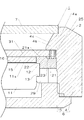
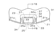
図1中符号1は、時計例えば携帯時計具体的には腕時計を示している。この腕時計1は、時計外装組立2と、モジュール例えばムーブメント11と、パネル例えば太陽電池パネル15と、リング部材21と、表示板例えば文字板31を具備している。
Hereinafter, a first embodiment of the present invention will be described in detail with reference to FIGS.
時計外装組立2は、胴4及び裏蓋5を有した金属製又は合成樹脂製の外装部材6と、カバーガラス7を備えている。裏蓋5は胴4にねじ込まれて連結されている。なお、外装部材6は、胴4と裏蓋5が一体に形成されたワンピース型の構成であってもよい。カバーガラス7は、胴4に形成されたガラス支持部4aの内側に液密に装着されている。
The
外装部材6は見切り4bを有している。図1に示された見切り4bは、胴4の内周に一体に形成されたものであるが、胴4と別体に成形されたリング形の部材であっても良い。見切り4bは斜面4cを有し、この斜面4cはカバーガラス7の周部裏面に対向している。
The
ムーブメント11は、後述の太陽電池パネル15が発電する電力で駆動されるものであって、図示しないが前記電力を蓄積するための二次電池或いはキャパシタ等を備えている。ムーブメント11は平面視円形である。このムーブメント11は時計外装組立2内に後述のリング部材21及び文字板31等とともに組込まれている。
The
このムーブメント11は係合部12を有している。係合部12は、ムーブメント11の周部でかつ上面11a側に設けられて、例えばムーブメント11の周方向に連続する環状凸部の上面部位で形成されている。図1に示すように係合部12は、ムーブメント11の上面11aに対してムーブメント11の裏側(下側)方向に若干後退している。
This
太陽電池パネル15は、図示しない基板に、光電変換により発電する発電素子としてソーラーセル(図示しない)が搭載されたパネルである。ソーラーセルは、結晶系であっても、アモルファス系であっても差し支えない。この太陽電池パネル15は、ムーブメント11の直径よりやや小径であり、接着部材16を用いてムーブメント11の上面11aに固定されている。接着部材16として両面が粘着性を有する両面接着テープを好適に使用できる。
The
リング部材21は、合成樹脂の例えばジュラコンの一体成形品である。リング部材21は、平面視リング形をなしていて、その内径は太陽電池パネル15の直径よりやや大きく、かつ、外径はムーブメント11の直径より大きい。リング部材21はその内面及び裏面(下面)に開放された係合溝22を有している。この係合溝22はリング部材21の周方向に連続して環状に形成されている。
The
更に、リング部材21は、その上面21aに凹み23及びこれと同数の係合凸部25を複数個所に有しているとともに、裏面複数個所にフック部29(図1に一個のみ図示)を有している。
Further, the
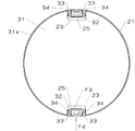
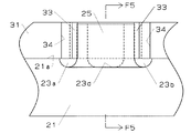
凹み23は図2に示すようにリング部材21の外周部の2箇所に例えば180度離れて設けられている。尚、凹み23は120度ごと三箇所に設けてもよく、或いは90度ごと四箇所に設けてもよい。各凹み23は、リング部材21の上面21a及び外周面に夫々開放されているとともに、図4及び図5に示す第1の凹み部位23a〜第4の凹み部位23dを有している。
As shown in FIG. 2, the
第1の凹み部位23aと第2の凹み部位23bは平行である。これら第1の凹み部位23aと第2の凹み部位23bの一端はいずれもリング部材21の外周面に開放されている。第3の凹み部位23cは、第1の凹み部位23aと第2の凹み部位23bの他端間にわたって設けられている。第4の凹み部位23dは、第1の凹み部位23aと第2の凹み部位23bの一端部間にわたって設けられていて、その長手方向全体にわたってリング部材21の外周面に開放されている。したがって、第1の凹み部位23a〜第4の凹み部位23dは例えば略四角環状をなして連続されている。
The first recessed portion 23a and the second recessed
係合凸部25は、各凹み23の底から一体に上向きに突出されている。そのため、係合凸部25の根元部全体がリング部材21の上面21aより下側に位置されていて、この根元部は、既述のように環状に連続した第1の凹み部位23a〜第4の凹み部位23dで囲まれている。
The engaging
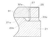
各係合凸部25は、その平面視形状が略四角形、好ましくは図3に示すように略長四角形であるとともに、上端に開放する内空部26を有している。係合凸部25は、その長辺をなした側面がリング部材21の径方向と直交するように設けられている。後述する凸部収容溝32の開放端に近い方の二つ角部、言い換えれば、リング部材21の外周に近い係合凸部25の二つの角部は、夫々接触部位25a(図3参照)として用いられている。
Each engagement
図4に示すように第1の凹み部位23a〜第3の凹み部位23cは半円状に凹んで形成されており、図5に示すように第4の凹み部位23dは1/4の円弧状をなすように凹んで形成されている。そのため、係合凸部25の根元部の側面と凹み23とは、互いの間に角を形成することなく連続されていて、それによって、係合凸部25は凹み23の底に向けて次第に太く形成されている。
As shown in FIG. 4, the first recessed portion 23a to the third recessed
図3及び図5に示すように係合凸部25は、リング部材21の外周から最も遠く位置された側面に、例えば2本のビード27を有している。ビード27は、その平面視形状が円弧状の凸部からなる。ビード27は係合凸部25の中心軸線(図示しない)が延びる方向と平行に延びている。図5に示すようにビード27の上端は係合凸部25の上端より若干下がっており、ビード27の下端は係合凸部25の根元部に達している。
As shown in FIGS. 3 and 5, the engagement
図1に示すようにリング部材21は、そのフック部29をムーブメント11の前記環状凸部の下面13に引掛けるとともに、係合溝22を係合部12の上面に係合することによって、ムーブメント11に取付けられている。以上の取付けによって、180度離れた凹み23が、図2に例示したように12時−6時の方向に配置されるとともに、各係合凸部25を除いたリング部材21の上面21aが、太陽電池パネル15の上面よりやや高く位置されるようになっている(図1参照)。なお、一対の凹み23の配置は、12時−6時の方向に制約されず、9時−3時の方向、或いはその他の方向に配置することも可能である。
As shown in FIG. 1, the
文字板31は、透明なアクリル樹脂やポリカーボネイト樹脂等の透光性で、かつ、リング部材21を成形した合成樹脂材料より硬い合成樹脂で薄板状に成形されている。文字板31は略円形でリング部材21の外径よりやや小径である。この文字板31には、図示しないが目盛、数字、模様等の表示が設けられている。
The
文字板31はその周部に複数の凸部収容溝32を有している。これらの凸部収容溝32は、文字板31をその周面から切欠くように形成されていて、文字板31の周面31aに開放されている。この開放された端を開放端と以下称する。各凸部収容溝32は、係合凸部25と同数でかつこれら係合凸部25の配置に適合して設けられている。したがって、図6に示すように二つの凸部収容溝32が文字板31の周方向に180度離れて設けられている。
The
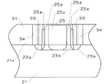
これら凸部収容溝32の幅方向両側は、図3に示すように挟み部33で区画されている。挟み部33は弾性変形が可能である。凸部収容溝32の幅つまり挟み部33間の距離は、凸部収容溝32の開口端側、言い換えれば、文字板31の周面31a側ほど狭くなるように形成されている。そのために、第1実施形態の場合、文字板31の周面31a側ほど挟み部33同士が近付くようにこれら挟み部33が傾斜されている。尚、こうした傾斜は片方の挟み部33のみに設けてもよい。凸部収容溝32を仕切った挟み部33の先端部間の距離、言い換えれば、凸部収容溝32の最小幅である開口端部の幅は、係合凸部25の二つの接触部位25aの離間距離より若干狭い。
Both sides in the width direction of the convex
文字板31は、太陽電池パネル15を覆ってリング部材21に取付けられている。この取付けは、ムーブメント11に装着されているリング部材21に対して、係合凸部25と文字板31の凸部収容溝32を位置合わせした状態で、リング部材21の上方から文字板31を下方に押圧することで実施できる。
The
それにより、挟み部33が主として文字板31の厚み方向に撓み変形(弾性変形)を起こしながら係合凸部25に凸部収容溝32が嵌合される。即ち、係合凸部25が凸部収容溝32に対して相対的に軽圧入されるに伴い、図3等に示すように挟み部33が係合凸部25の接触部位25aに密接されて、これら挟み部33が係合凸部25をリング部材21の径方向と直交する方向に沿った挟んだ状態となる。これとともに、ビード27が凸部収容溝32の溝底面32aに接触される。
As a result, the convex
こうした状態が維持されたままで、文字板31の裏面がリング部材21の上面21aに当たることで、前記押圧操作が阻止される。これにより、各係合凸部25が夫々に対応された各凸部収容溝32に納められて、文字板31が太陽電池パネル15を覆ってリング部材21に取付けられる。
With this state maintained, the pressing operation is prevented by the back surface of the
この場合、挟み部33が密接する接触部位25aは、リング部材21の外周面側に寄せて係合凸部25に設けられているので、挟み部33の根元から接触部位25aへの密接箇所までの長さが長く確保されている。しかも、凸部収容溝32の幅がこの溝の開放端に向けて次第に狭くなるように挟み部33が夫々それらの先端側ほど互に近付くように傾けられているので、これら挟み部33の根元から接触部位25aまでの長さを、凸部収容溝32の幅に変化がない構成に比較して、より長く確保できる。
In this case, the contact portion 25a with which the sandwiching
これにより、以上説明した文字板31の取付け操作において、主として挟み部33を文字板31の厚み方向に容易に弾性変形させてリング部材21に文字板31を取付けることができ、その際、係合凸部25がその根元部を支点に無理に変形されることがない。
Thereby, in the operation of attaching the
しかも、係合凸部25はその上端に開放する内空部26を有しているので、文字板31が取付けられる際において、係合凸部25に大きい力が作用した場合、この係合凸部25は縮径するように多少撓むことが可能である。このため、係合凸部25をその根元から曲げられないようにしながら、リング部材21への文字板31の取付け作業をより容易に行うことが可能である。
Moreover, since the engagement
又、係合凸部25の根元部はそれより上側部位よりも太く形成されているが、この根元部はリング部材21の上面21aより下側に位置されている。そのため、既述の文字板31の取付けにおいて、文字板31の裏面がリング部材21の上面21aに当たることを、係合凸部25の根元部が妨げることがない。
Further, the base part of the engaging
図3及び図6等に示すように文字板31は、その周面に開放された複数の逃げ溝34を有している。これら逃げ溝34と凸部収容溝32との間は挟み部33である。各逃げ溝34は文字板31の周部を例えばV字状に切欠くように形成されていて、その深さは例えば凸部収容溝32の深さと略同じである。凸部収容溝32の奥の角部と逃げ溝34の奥部との間は挟み部33の根元部となっており、この根元部を支点に挟み部33は逃げ溝34の幅を狭める方向に弾性変形が可能である。
As shown in FIGS. 3 and 6, the
このため、文字板31が取付けられる際に、挟み部33は逃げ溝34側に逃げながら弾性変形することも可能であるので、挟み部33の弾性変形がより容易となる。この結果、係合凸部25の変形を抑制しつつ、リング部材21に対する文字板31の取付け作業をより容易に行うことが可能である。
以上の取付けにより、文字板31はがたつかないように保持される。
For this reason, when the
With the above attachment, the
即ち、文字板31の挟み部33がリング部材21の係合凸部25に弾性的に密接されていることで、文字板31をその周方向にがたつかないように保持することが可能である。更に、凸部収容溝32の幅がこの溝の開放端に向けて次第に狭くなっているので、リング部材21に取付けられた文字板31がその凸部収容溝32を結ぶ径方向に動こうとしても、その移動方向と反対側に位置されている係合凸部25とこれが収められている凸部収容溝32において、係合凸部25がストッパとして機能し、係合凸部25とこれを挟んだ挟み部33との密接が強められる。これとともに、凸部収容溝32の溝底面32aに係合凸部25のビード27が接していることで、リング部材21に取付けられた文字板31がその凸部収容溝32を結ぶ径方向に移動しようとしても、係合凸部25をストッパとして抑制できる。したがって、文字板31がその凸部収容溝32を径方向にがたつかないように保持することが可能である。
That is, since the sandwiching
尚、この保持状態では、図3に示されるように斜めの挟み部33とこれに対向した係合凸部25の側面と間に、挟み部33の先端部と接触部位25aとの接触箇所を起点として、凸部収容溝32の溝底面32aに向けて次第に広がる隙間が形成されている。
In this holding state, as shown in FIG. 3, the contact portion between the tip end portion of the sandwiching
既述のように文字板31の挟み部33が長いことと相まって、この挟み部を凸部収容溝32との間に挟みように文字板31に設けられた逃げ溝34によって、弾性変形がより容易である。このため、係合凸部25を挟んだ挟み部33によって、リング部材21に取付けられた文字板31にこれをうねるように変形させる程の過大な反力を与えられることが抑制され、そのような力は、挟み部33が逃げ溝34を狭めるように弾性変形することで吸収される。したがって、凸部収容溝32を起点として透明な文字板31がうねった状態となった場合の不具合、つまり、文字板31の各部での光の反射が異なって、文字板31がうねった状態が容易に視認可能となり、腕時計1の体裁が損なわれる、という不具合が生じないようにできる。
As described above, coupled with the fact that the sandwiching
又、既述のように係合凸部25にストッパ機能があることで、挟み部33が係合凸部25の接触部位25aに密接する力を小さくすることが可能である、これにより、文字板31をリング部材21に取付ける際における挟み部33の弾性変形がより容易となる結果、文字板31の取付け作業をより容易に行うことが可能である。
Further, as described above, since the engaging
以上のように取付けられた文字板31は、図1に示したようにカバーガラス7の裏面に対向され、かつ、この文字板31の周部は前記見切り4bで覆われている。文字板31は透明であるので、カバーガラス7及び文字板31を透過した自然光又は人工光が太陽電池パネル15に入射されるに伴い、この太陽電池パネル15のソーラーセルは光電変換して発電する。したがって、この腕時計1は、以上のように発電された電力を二次電池やキャパシタに蓄えて、その電力でムーブメント11を駆動することができる。
The
又、リング部材21に取付けられた文字板31の凸部収容溝32の周部は、リング部材21の上面21aに接して凹み23を覆っているが、この凹み23は図4に示すようにリング部材21の外周面に開放されている。そのため、文字板31の取付けが不良で、文字板31の組み直しを行う際やメンテナンスにおいて、文字板31をリング部材21から外す場合、文字板31を外すためのピンセット等の工具(図示しない)を、リング部材21の外側から凹み23の第1の凹み部位23a又は第2の凹み部位23b、若しくはこれらの双方に、容易に挿入できる。
Further, the peripheral portion of the convex
それにより、工具を文字板31の裏側に配置した上で、リング部材21の係合凸部25に係合されている文字板31を、工具でこじ上げて外すことができる。加えて、このこじ上げる操作を、係合凸部25の近傍位置で行うことができる。しかも、既述のように斜めの挟み部33はその全長が長く、加えて逃げ溝34が文字板31に設けられていることで、文字板31をリングに材21に取付けるときと同様に挟み部33の弾性変形が容易であるので、前記こじ上げる操作に過大な操作力を要しない。よって、文字板31を容易に外すことができる。
Accordingly, the
又、既述のようにリング部材21に設けた凹み23の底から係合凸部25が上向きに突設されて、各係合凸部25の根元部はリング部材21の上面21aより下側に位置されているため、各係合凸部25の全長が凹み23の深さに応じて長い。これにより、係合凸部25がその根元部を支点に曲げられることがあっても、その弾性変形が比較的容易であり、その際に係合凸部25の根元部にそこへの応力集中を原因とするクラックが発生する恐れがない。
Further, as described above, the engaging
しかも、係合凸部25の根元部は、凹み23の底に向けて次第に太く形成されていて、凹み23の底と根元部の周面は、これらの間に角を形成することなく連続しているとともに、係合凸部25の根元部より上側部位と根元部の周面も、それらの間に角を形成することなく連続している。このため、根元部に応力が集中し難いことに伴い、腕時計1に加わる振動等の外力によって係合凸部25の根元部にクラックを生じる恐れが低減されて、リング部材21への文字板31の所定の取付け状態を確実に維持することができる。
In addition, the base portion of the engaging
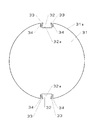
図7及び図8は本発明の第2実施形態を示している。この第2実施形態に係る腕時計は、以下説明する構成以外は図7及び図8に示されていない構成を含めて第1実施形態と同じである。そのため、第1実施形態と同じ構成については第1実施形態と同じ符号を付して、その説明を省略する。 7 and 8 show a second embodiment of the present invention. The wristwatch according to the second embodiment is the same as that of the first embodiment except for the configuration described below, including configurations not shown in FIGS. 7 and 8. Therefore, the same components as those of the first embodiment are denoted by the same reference numerals as those of the first embodiment, and description thereof is omitted.
第2実施形態では、リング部材21の平面視略四角形の係合凸部25が、その上端に開放される内空部を有することなく中実に形成されている。
In the second embodiment, the engagement
これ以外の構成は図7及び図8に示されていない構成を含めて第1実施形態と同じである。そのため、第2実施形態では、第1実施形態で既に説明したのと同じ理由によって、第1実施形態と同じ作用を得て、本発明の課題を解決できる。即ち、リング部材21に対する文字板31の取付け作業及び文字板31の組み直し作業が容易であるとともに、表示板である文字板31の組み直しに伴う文字板31の取付け不良を抑制可能な腕時計を提供できる。
The other configuration is the same as that of the first embodiment including the configuration not shown in FIGS. Therefore, in 2nd Embodiment, the same effect | action as 1st Embodiment is acquired for the same reason already demonstrated in 1st Embodiment, and the subject of this invention can be solved. That is, it is possible to provide a wristwatch in which the attaching work of the
しかも、第2実施形態では、係合凸部25が中実であるので、文字板31が着脱される際に係合凸部25の変形が起こり難いことに伴い、文字板31の組み直しに伴う文字板31の取付け不良を生じることを抑制可能である。加えて、係合凸部25の構成が単純であるに伴い、リング部材21を成形する成形型の構造も単純化するので、型費の低減に伴うコストダウンを期待することが可能である。
Moreover, in the second embodiment, since the engaging
図9及び図10は本発明の第3実施形態を示している。この第3実施形態に係る腕時計は、以下説明する構成以外は図9及び図10に示されていない構成を含めて第1実施形態と同じである。そのため、第1実施形態と同じ構成については第1実施形態と同じ符号を付して、その説明を省略する。 9 and 10 show a third embodiment of the present invention. The watch according to the third embodiment is the same as that of the first embodiment except for the configuration described below, including the configuration not shown in FIGS. 9 and 10. Therefore, the same components as those of the first embodiment are denoted by the same reference numerals as those of the first embodiment, and description thereof is omitted.
第3実施形態では、係合凸部25が、凸部収容溝32の溝底面32aに対向された壁部25cと、この壁部25cの幅方向両端部から夫々凸部収容溝32の開放端に向けて折れ曲がるように設けられて相対向した他の壁部25dとを有していて、平面視略コの字形、言い換えれば、溝形に形成されている。これら他の壁部25dの前記開放端側の端部に接触部位25aが設けられているとともに、これらの接触部位25aは、前記端部外面に一体に形成されて上下方向にも乗るビードにより形成されている。
In 3rd Embodiment, the engagement
以上説明した以外の構成は図9及び図10に示されていない構成を含めて第1実施形態と同じである。そのため、第3実施形態では、第1実施形態で既に説明したのと同じ理由によって、第1実施形態と同じ作用を得て、本発明の課題を解決できる。即ち、リング部材21に対する文字板31の取付け作業及び文字板31の組み直し作業が容易であるとともに、表示板である文字板31の組み直しに伴う文字板31の取付け不良を抑制可能な腕時計を提供できる。
Configurations other than those described above are the same as those in the first embodiment, including configurations not shown in FIGS. 9 and 10. Therefore, in 3rd Embodiment, the same effect | action as 1st Embodiment is acquired for the same reason already demonstrated in 1st Embodiment, and the subject of this invention can be solved. That is, it is possible to provide a wristwatch in which the attaching work of the
しかも、第3実施形態では、挟み部33の弾性変形に加えて、係合凸部25の接触部位25aが設けられた他の壁部25dは、互に近付く方向に倒れるように撓む(弾性変形する)ことが可能である。このため、文字板31が着脱される際に、文字板31の挟み部33が主に弾性変形するだけではなく、他の壁部25dも弾性変形するに伴い、文字板31の着脱作業をより容易に行うことが可能である。
Moreover, in the third embodiment, in addition to the elastic deformation of the sandwiching
これとともに、他の壁部25dが弾性変形可能であることにより、リング部材21と文字板31との硬さが異なるにも拘らず、係合凸部25の接触部位25aが挟み部33で削られ難くなる。そのため、接触部位25aが削られた場合のように挟み部33が係合凸部25を挟み力が低減され難いので、文字板31をリング部材21に対してがたつかないように保持する上で好ましい。
At the same time, since the
更に、接触部位25aをビードにより形成した構成により、傾斜された挟み部33との接触箇所が、挟み部33の先端から少し根元側にずれるので、二つの凸部収容溝32を結ぶ文字板31の径方向に文字板31が動こうとしたときに発揮される係合凸部25のストッパ機能の信頼性を高めることが可能である。尚、接触部位25aをビードにより形成する構成は、第1、第2の実施形態、及び次に説明する第4の実施形態にも適用可能である。
Furthermore, because the contact portion 25a is formed of a bead, the contact portion with the inclined pinching
図11及び図12は本発明の第4実施形態を示している。この第4実施形態に係る腕時計は、以下説明する構成以外は図11及び図12に示されていない構成を含めて第3実施形態と同じである。そのため、第1実施形態と同じ構成については第1実施形態と同じ符号を付して、その説明を省略する。 11 and 12 show a fourth embodiment of the present invention. The wristwatch according to the fourth embodiment is the same as that of the third embodiment except for the configuration described below, including configurations not shown in FIGS. 11 and 12. Therefore, the same components as those of the first embodiment are denoted by the same reference numerals as those of the first embodiment, and description thereof is omitted.
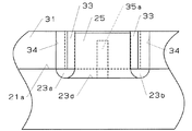
第4実施形態では、リング部材21の係合凸部25が、凸部収容溝32の溝底面32aと平行で、かつ、リング部材21の径方向に弾性変形が可能な板状壁で形成されている。この係合凸部25の幅方向両端部は接触部位25aである。更に、リング部材21には、板状壁からなる係合凸部25とこれが収容された凸部収容溝32の溝底面32aとの間に上向きの規制凸部35が設けられている。規制凸部35はリング部材21の径方向に弾性変形が可能である。この規制凸部35は凸部収容溝32の溝底面32aに接するビードからなる接触部35aを有している。接触部35aは第1実施形態で説明したビード27と同様な機能を得るために設けられている。
In the fourth embodiment, the engaging
以上説明した以外の構成は図11及び図12に示されていない構成を含めて第1実施形態と同じである。そのため、第4実施形態では、第1実施形態で既に説明したのと同じ理由によって、第1実施形態と同じ作用を得て、本発明の課題を解決できる。即ち、リング部材21に対する文字板31の取付け作業及び文字板31の組み直し作業が容易であるとともに、文字板31の組み直しに伴う文字板31の取付け不良を抑制可能な腕時計を提供できる。
Configurations other than those described above are the same as those in the first embodiment, including configurations not shown in FIGS. 11 and 12. Therefore, in the fourth embodiment, the same effect as that of the first embodiment can be obtained for the same reason as already described in the first embodiment, and the problem of the present invention can be solved. That is, it is possible to provide a wristwatch in which the attaching work of the
しかも、第4実施形態では、文字板31が着脱される際、挟み部33の弾性変形に加えて、係合凸部25がリング部材21の径方向に弾性変形することが可能であるので、文字板31の着脱作業をより容易に行うことが可能である。これとともに、係合凸部25の弾性変形が可能であることにより、リング部材21と文字板31との硬さが異なるにも拘らず、係合凸部25の接触部位25aが挟み部33で削られ難くなる。そのため、接触部位25aが削られた場合のように挟み部33が係合凸部25を挟み力が低減されないので、文字板31をリング部材21に対してがたつかないように保持する上で好ましい。又、係合凸部25の構成が板状で単純であるので、リング部材21を成形する成形型の型費の低減に伴うコストダウンを期待することが可能である。
In addition, in the fourth embodiment, when the
なお、本発明は前記各実施形態には制約されない。例えば、前記各実施形態において太陽電池パネルに代えて発光パネルを用いることが可能である。発光パネルには、例えばエレクトロルミネッセンスからなるパネルを好適に使用でき、この発光パネルは、時計外装組立に内蔵された二次電池等から供給される電力で発光される。こうして実施する場合には、発光パネルがそれへの通電で発光して、この発光パネルで表示板に対するバックライト照明ができるため、時刻等の表示の視認性をより向上できる。又、本発明は、腕時計以外に懐中時計等にも適用できる。 In addition, this invention is not restrict | limited to the said each embodiment. For example, in each of the embodiments, a light emitting panel can be used instead of the solar cell panel. As the light-emitting panel, for example, a panel made of electroluminescence can be suitably used, and this light-emitting panel emits light with electric power supplied from a secondary battery or the like built in the watch exterior assembly. When implemented in this way, the light-emitting panel emits light when it is energized, and the light-emitting panel can perform backlight illumination on the display plate. Therefore, the visibility of the display such as time can be further improved. Further, the present invention can be applied to a pocket watch or the like in addition to a wristwatch.
1…腕時計(時計)
11…ムーブメント(モジュール)
15…太陽電池パネル(パネル)
21…リング部材
25…係合凸部
25a…接触部位
25c…壁部
25d…他の壁部
26…内空部
31…文字板(表示板)
32…凸部収容溝
32a…凸部収容溝の溝底面
33…挟み部
34…逃げ溝
35…規制凸部
1 ... Wristwatch
11 ... Movement (module)
15 ... Solar panel (panel)
DESCRIPTION OF
32 ... Convex part receiving groove 32a ... Groove bottom face of convex
Claims (11)
このモジュール上に固定されたパネルと、
前記モジュールの周部に固定された平面視リング形のリング部材であって、この部材の複数個所に上向きの係合凸部が形成されていて、この係合凸部が前記リング部材の外周面に寄って配置された接触部位を有している前記リング部材と、
前記パネルを覆って配設された表示板であって、この表示板の周面に開放された複数の凸部収容溝、及びこの収容溝を区画しかつ弾性変形された状態で前記接触部位に密接されて前記係合凸部を前記リング部材の径方向と直交する方向に沿って挟む挟み部を複数有しており、前記各凸部収容溝を前記各係合凸部に夫々収めて前記リング部材に取付けられた前記表示板と、
を具備することを特徴とする時計。 Module,
A panel fixed on this module;
A ring member having a ring shape fixed to the peripheral portion of the module, and upward engaging convex portions are formed at a plurality of positions of the member, and the engaging convex portions are outer peripheral surfaces of the ring member. The ring member having a contact portion disposed near the
A display plate disposed to cover the panel, the plurality of convex portion receiving grooves opened on the peripheral surface of the display plate, and the contact groove in a state of partitioning and elastically deforming the receiving grooves It has a plurality of pinching portions that are in close contact and sandwich the engaging convex portion along a direction orthogonal to the radial direction of the ring member, and each convex receiving groove is housed in each engaging convex portion. The display plate attached to the ring member;
A watch comprising:
Priority Applications (4)
| Application Number | Priority Date | Filing Date | Title |
|---|---|---|---|
| JP2011053461A JP5623314B2 (en) | 2011-03-10 | 2011-03-10 | clock |
| US13/414,776 US8547802B2 (en) | 2011-03-10 | 2012-03-08 | Timepiece |
| CN201210070794.XA CN102681420B (en) | 2011-03-10 | 2012-03-09 | Clock and watch |
| CH00345/12A CH705046B1 (en) | 2011-03-10 | 2012-03-12 | Watch comprising an electronic or analog display module. |
Applications Claiming Priority (1)
| Application Number | Priority Date | Filing Date | Title |
|---|---|---|---|
| JP2011053461A JP5623314B2 (en) | 2011-03-10 | 2011-03-10 | clock |
Publications (2)
| Publication Number | Publication Date |
|---|---|
| JP2012189458A true JP2012189458A (en) | 2012-10-04 |
| JP5623314B2 JP5623314B2 (en) | 2014-11-12 |
Family
ID=46813504
Family Applications (1)
| Application Number | Title | Priority Date | Filing Date |
|---|---|---|---|
| JP2011053461A Active JP5623314B2 (en) | 2011-03-10 | 2011-03-10 | clock |
Country Status (4)
| Country | Link |
|---|---|
| US (1) | US8547802B2 (en) |
| JP (1) | JP5623314B2 (en) |
| CN (1) | CN102681420B (en) |
| CH (1) | CH705046B1 (en) |
Families Citing this family (7)
| Publication number | Priority date | Publication date | Assignee | Title |
|---|---|---|---|---|
| EP2672331B1 (en) * | 2012-06-06 | 2017-11-15 | Omega SA | Timepiece case with exterior element with improved attachment |
| JP5742830B2 (en) * | 2012-12-14 | 2015-07-01 | カシオ計算機株式会社 | Interior part positioning structure, timepiece, and interior part positioning method |
| JP6132162B2 (en) * | 2014-03-24 | 2017-05-24 | カシオ計算機株式会社 | Timing device and watch |
| CN106164785B (en) * | 2014-03-25 | 2018-10-02 | Eta瑞士钟表制造股份有限公司 | Clock and watch equipped with dial plate and relevant fastening method |
| EP3276433B1 (en) * | 2016-07-26 | 2019-05-15 | Omega SA | Casing subassembly for a timepiece, watch or jewel |
| EP3816734A1 (en) | 2019-11-04 | 2021-05-05 | ETA SA Manufacture Horlogère Suisse | Electronic watch with solar cell |
| EP3822494A1 (en) * | 2019-11-13 | 2021-05-19 | ETA SA Manufacture Horlogère Suisse | Member and device for attaching a disc |
Citations (6)
| Publication number | Priority date | Publication date | Assignee | Title |
|---|---|---|---|---|
| JPS4951266U (en) * | 1972-08-09 | 1974-05-07 | ||
| JPS5132566U (en) * | 1974-08-29 | 1976-03-10 | ||
| JPS5451873U (en) * | 1977-09-19 | 1979-04-10 | ||
| WO1995027234A1 (en) * | 1994-03-31 | 1995-10-12 | Citizen Watch Co., Ltd. | Timepiece having light transmission type display plate |
| JP2000321373A (en) * | 1999-04-22 | 2000-11-24 | Eta Sa Fab Ebauches | Watch |
| JP2004257918A (en) * | 2003-02-27 | 2004-09-16 | Citizen Watch Co Ltd | Fixing structure of indication plate for watch |
Family Cites Families (6)
| Publication number | Priority date | Publication date | Assignee | Title |
|---|---|---|---|---|
| KR100242601B1 (en) * | 1994-10-21 | 2000-04-01 | 이쿠노 도모히사 | Dial for solar cell timepiece and production method thereof |
| US5936914A (en) * | 1995-08-16 | 1999-08-10 | Casio Computer Co., Ltd. | Electronic appliance equipped with light emitting apparatus |
| DE69935656T2 (en) * | 1999-04-22 | 2007-12-13 | Eta Sa Manufacture Horlogère Suisse | Method for mounting a housing ring in a watch case and housing ring that can be used for this purpose |
| JP4398555B2 (en) | 2000-01-13 | 2010-01-13 | シチズンホールディングス株式会社 | Clock display board fixing structure |
| JP2003227884A (en) * | 2001-11-29 | 2003-08-15 | Casio Comput Co Ltd | Light emission and display device and electronic apparatus |
| JP2010133756A (en) * | 2008-12-03 | 2010-06-17 | Casio Computer Co Ltd | Mounting structure of dial plate |
-
2011
- 2011-03-10 JP JP2011053461A patent/JP5623314B2/en active Active
-
2012
- 2012-03-08 US US13/414,776 patent/US8547802B2/en active Active
- 2012-03-09 CN CN201210070794.XA patent/CN102681420B/en active Active
- 2012-03-12 CH CH00345/12A patent/CH705046B1/en unknown
Patent Citations (6)
| Publication number | Priority date | Publication date | Assignee | Title |
|---|---|---|---|---|
| JPS4951266U (en) * | 1972-08-09 | 1974-05-07 | ||
| JPS5132566U (en) * | 1974-08-29 | 1976-03-10 | ||
| JPS5451873U (en) * | 1977-09-19 | 1979-04-10 | ||
| WO1995027234A1 (en) * | 1994-03-31 | 1995-10-12 | Citizen Watch Co., Ltd. | Timepiece having light transmission type display plate |
| JP2000321373A (en) * | 1999-04-22 | 2000-11-24 | Eta Sa Fab Ebauches | Watch |
| JP2004257918A (en) * | 2003-02-27 | 2004-09-16 | Citizen Watch Co Ltd | Fixing structure of indication plate for watch |
Also Published As
| Publication number | Publication date |
|---|---|
| CH705046A2 (en) | 2012-11-15 |
| JP5623314B2 (en) | 2014-11-12 |
| US20120257481A1 (en) | 2012-10-11 |
| CH705046B1 (en) | 2017-07-31 |
| US8547802B2 (en) | 2013-10-01 |
| CN102681420B (en) | 2015-11-25 |
| CN102681420A (en) | 2012-09-19 |
Similar Documents
| Publication | Publication Date | Title |
|---|---|---|
| JP5782274B2 (en) | clock | |
| JP5623314B2 (en) | clock | |
| JP5946390B2 (en) | Electronic watch with solar cell | |
| JP2009163672A (en) | Display | |
| US20080031007A1 (en) | Housing for backlight module, backlight module and liquid crystal display device | |
| JP5462038B2 (en) | clock | |
| US7682065B2 (en) | Backlight module having holding device for holding light source | |
| JP3633446B2 (en) | Clock with solar battery | |
| JP5946368B2 (en) | Electronic watch with solar cell | |
| JP5142043B2 (en) | Dial structure | |
| JP2009238838A (en) | Electronic apparatus comprising solar cell panel | |
| JP2010133756A (en) | Mounting structure of dial plate | |
| JP5144448B2 (en) | Electronic watch with solar cell | |
| JP2009282435A (en) | Display | |
| JP2013029468A (en) | Component fixing structure | |
| JP2013029468A5 (en) | ||
| JP5182438B2 (en) | Display device | |
| JP2013029469A (en) | Electronic timepiece with solar battery | |
| JP6117656B2 (en) | Electronic watch with solar cell | |
| JP2020095059A (en) | Timepiece with solar cell | |
| JP5921407B2 (en) | A watch having a regulating portion for an external operation member | |
| JP2009229358A (en) | Electronic timepiece with solar cell | |
| JP5589693B2 (en) | Display device and clock device | |
| JP2003057369A (en) | Electronic timepiece | |
| JP2017146216A (en) | Timepiece with solar cell |
Legal Events
| Date | Code | Title | Description |
|---|---|---|---|
| A621 | Written request for application examination |
Free format text: JAPANESE INTERMEDIATE CODE: A621 Effective date: 20140116 |
|
| RD03 | Notification of appointment of power of attorney |
Free format text: JAPANESE INTERMEDIATE CODE: A7423 Effective date: 20140117 |
|
| A977 | Report on retrieval |
Free format text: JAPANESE INTERMEDIATE CODE: A971007 Effective date: 20140828 |
|
| TRDD | Decision of grant or rejection written | ||
| A01 | Written decision to grant a patent or to grant a registration (utility model) |
Free format text: JAPANESE INTERMEDIATE CODE: A01 Effective date: 20140916 |
|
| A61 | First payment of annual fees (during grant procedure) |
Free format text: JAPANESE INTERMEDIATE CODE: A61 Effective date: 20140924 |
|
| R150 | Certificate of patent or registration of utility model |
Ref document number: 5623314 Country of ref document: JP Free format text: JAPANESE INTERMEDIATE CODE: R150 |
|
| R250 | Receipt of annual fees |
Free format text: JAPANESE INTERMEDIATE CODE: R250 |
|
| R250 | Receipt of annual fees |
Free format text: JAPANESE INTERMEDIATE CODE: R250 |
|
| R250 | Receipt of annual fees |
Free format text: JAPANESE INTERMEDIATE CODE: R250 |
|
| R250 | Receipt of annual fees |
Free format text: JAPANESE INTERMEDIATE CODE: R250 |
|
| R250 | Receipt of annual fees |
Free format text: JAPANESE INTERMEDIATE CODE: R250 |
|
| R250 | Receipt of annual fees |
Free format text: JAPANESE INTERMEDIATE CODE: R250 |
|
| R250 | Receipt of annual fees |
Free format text: JAPANESE INTERMEDIATE CODE: R250 |