JP2012187807A - Three-dimensional molding machine - Google Patents
Three-dimensional molding machine Download PDFInfo
- Publication number
- JP2012187807A JP2012187807A JP2011053110A JP2011053110A JP2012187807A JP 2012187807 A JP2012187807 A JP 2012187807A JP 2011053110 A JP2011053110 A JP 2011053110A JP 2011053110 A JP2011053110 A JP 2011053110A JP 2012187807 A JP2012187807 A JP 2012187807A
- Authority
- JP
- Japan
- Prior art keywords
- shutter
- tank
- molding machine
- opening
- resin
- Prior art date
- Legal status (The legal status is an assumption and is not a legal conclusion. Google has not performed a legal analysis and makes no representation as to the accuracy of the status listed.)
- Granted
Links
Images
Abstract
【課題】槽内の光硬化性樹脂が台の上に飛び散ったとしても3次元物体の生成効率が低下しない3次元造型機を提供する。
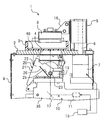
【解決手段】3次元造型機1は、液体状の光硬化性の樹脂40を収容する槽3が載置される台2と、台2の下方に配置され、少なくとも光を発する光源11を有し、台2の開口4を通じて光源11からの光を槽3内の樹脂40に照射する光学装置10と、光が照射されて硬化した樹脂を引き上げる昇降自在なホルダ8と、開口4を開閉自在に覆うシャッター20と、を備える。
【選択図】図1
The present invention provides a three-dimensional molding machine in which the generation efficiency of a three-dimensional object does not decrease even if a photocurable resin in a tank is scattered on a table.
A three-dimensional molding machine (1) has a table (2) on which a tank (3) containing a liquid photocurable resin (40) is placed, and a light source (11) that is disposed below the table (2) and emits at least light. The optical device 10 that irradiates the resin 40 in the tank 3 with the light from the light source 11 through the opening 4 of the table 2, the up and down holder 8 that pulls up the cured resin when irradiated with the light, and the opening 4 can be opened and closed. And a shutter 20 for covering.
[Selection] Figure 1
Description
本発明は3次元造型機に関する。 The present invention relates to a three-dimensional molding machine.
従来から、槽内に収容された液体状の光硬化性樹脂に光を照射し、上記樹脂を硬化させることによって3次元物体を生成する3次元造型機が知られている。例えば特許文献1には、そのような3次元造型機が開示されている。
2. Description of the Related Art Conventionally, a three-dimensional molding machine that generates a three-dimensional object by irradiating light onto a liquid photocurable resin accommodated in a tank and curing the resin is known. For example,
特許文献1に開示された3次元造型機は、開口が形成された台と、台の上に載置された槽と、槽の上方に配置された昇降自在なキャリアプラットホームとを備えている。槽の中には、光が照射されると硬化する液体材料が収容されている。以下では、上記液体材料は光硬化性の樹脂であるとして説明する。台の下方には、光源および反射鏡等が配置されている。光源から照射された光は反射鏡で反射され、開口を通じて槽内の樹脂に照射される。光が照射された樹脂は硬化する。光の照射位置を制御することにより、硬化する樹脂の位置を適宜変更することができ、硬化後の樹脂によって所望の断面形状を形成することができる。キャリアプラットホームを順次上昇させることにより、所望の断面形状が下方に向かって連続的に形成される。これにより、硬化後の樹脂によって所望の3次元物体が生成される。
The three-dimensional molding machine disclosed in
ところで、3次元造型機では、3次元物体を生成する前に、液体状の樹脂が収容された槽を台の上に載置する作業が必要である。また、3次元物体を生成した後に、液体状の樹脂が残った槽を台の上から移動させる作業が必要である。この際、樹脂が台の上に飛び散り、開口を通じて反射鏡等に付着してしまう場合がある。しかし、光硬化性樹脂が反射鏡等に付着してしまうと、反射鏡等の性能を低下させるおそれがある。 By the way, in a three-dimensional molding machine, before producing | generating a three-dimensional object, the operation | work which mounts the tank in which liquid resin was accommodated on a stand is required. Further, after generating the three-dimensional object, it is necessary to move the tank in which the liquid resin remains from the top. At this time, the resin may scatter on the table and adhere to the reflecting mirror or the like through the opening. However, if the photocurable resin adheres to the reflecting mirror or the like, the performance of the reflecting mirror or the like may be reduced.
開口を通じて樹脂が反射鏡等に付着しないように、透明な板で開口を塞いでしまうことが考えられる。しかし、光源から発せられた光が樹脂に照射される前に、上記透明板で減衰されてしまい、樹脂を効率的に硬化できなくなるおそれがある。そのため、樹脂を効率的に硬化させるためには、出力の大きな光源が必要になる。また、樹脂が反射鏡に付着することを防止できたとしても、開口を塞ぐ透明板に樹脂が付着してしまい、付着した樹脂によって光源からの光が遮られてしまうおそれがある。 It is conceivable that the opening is blocked with a transparent plate so that the resin does not adhere to the reflecting mirror or the like through the opening. However, before the light emitted from the light source is applied to the resin, the resin is attenuated by the transparent plate, and the resin may not be cured efficiently. Therefore, in order to cure the resin efficiently, a light source with a large output is required. Even if the resin can be prevented from adhering to the reflecting mirror, the resin adheres to the transparent plate that closes the opening, and the light from the light source may be blocked by the adhering resin.
本発明はかかる点に鑑みてなされたものであり、その目的とするところは、樹脂が台の上に飛び散ったとしても3次元物体の生成効率が低下しない3次元造型機を提供することにある。 The present invention has been made in view of the above points, and an object of the present invention is to provide a three-dimensional molding machine in which the generation efficiency of a three-dimensional object does not decrease even when resin is scattered on a table. .
本発明に係る3次元造型機は、開口が形成され、液体状の光硬化性の樹脂を収容する槽が載置される台と、前記台の下方に配置され、少なくとも光を発する光源を有し、前記開口を通じて前記光源からの光を前記槽内の前記樹脂に照射する光学装置と、前記光が照射されて硬化した前記樹脂を引き上げる昇降自在なホルダと、前記開口を開閉自在に覆うシャッターと、を備えたものである。 The three-dimensional molding machine according to the present invention has a base on which a tank in which an opening is formed and a liquid photocurable resin is placed, and a light source that emits light at least. And an optical device for irradiating the resin in the tank with light from the light source through the opening, a liftable holder for pulling up the resin cured by the light, and a shutter for opening and closing the opening. And.
前記3次元造型機によれば、樹脂が入った槽を台の上に載置する際および台の上から離反させる際にシャッターを閉じておくことにより、槽から飛び散った樹脂が開口を通じて光学装置に付着することを防止することができる。また、槽から飛び散った樹脂がシャッターに付着したとしても、樹脂に光を照射する際にはシャッターを開くので、シャッターに付着した樹脂が上記照射を邪魔することはない。よって、3次元物体の生成効率が低下するおそれはない。 According to the three-dimensional molding machine, when the tank containing the resin is placed on the table and when the tank is moved away from the table, the shutter is closed to allow the resin scattered from the tank to pass through the opening through the optical device. Can be prevented from adhering to the surface. Further, even if the resin splashed from the tank adheres to the shutter, the shutter is opened when the resin is irradiated with light, so that the resin adhered to the shutter does not interfere with the irradiation. Therefore, there is no possibility that the generation efficiency of the three-dimensional object is lowered.
本発明によれば、樹脂が台の上に飛び散ったとしても3次元物体の生成効率が低下しない3次元造型機を提供することができる。 According to the present invention, it is possible to provide a three-dimensional molding machine in which the generation efficiency of a three-dimensional object does not decrease even if resin is scattered on a table.
図1に示すように、3次元造型機1は、槽3が載置される台2と、槽3内に収容される光硬化性樹脂40に光を照射する光学装置10と、硬化した樹脂を引き上げるホルダ8とを備えている。
As shown in FIG. 1, the three-
槽3は、光を透過させることのできる材料、例えば透明な樹脂またはガラス等で形成されたものである。本実施形態では、槽3は透明なアクリル樹脂で形成されている。図示は省略するが、槽3の底板の表面には、光硬化性樹脂40が固着してしまうことを抑制する層、例えばシリコン層が設けられている。
The
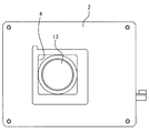
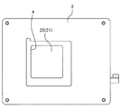
図2は台2の平面図である。図2に示すように、台2には開口4が形成されている。開口4の形状は特に限定される訳ではないが、本実施形態では略矩形状に形成されている。光学装置10からの光は、開口4を通じて、槽3内の光硬化性樹脂40に照射される。
FIG. 2 is a plan view of the table 2. As shown in FIG. 2, an
図1に示すように、光学装置10はケース9内に収容されている。光学装置10は、光を発する光源11と、光源11からの光を反射する鏡12と、鏡12によって反射された光を集光するレンズ13を備えている。
As shown in FIG. 1, the
鏡12の角度は自由に制御することができる。鏡12の角度を制御することにより、槽3内における光の照射位置を適宜変更することができる。光の照射位置を適宜変更することにより、所望の位置で光硬化性樹脂40を硬化させることができ、硬化後の樹脂によって所望の断面形状を形成することができる。
The angle of the
光源11の種類は何ら限定されないが、例えば、レーザダイオード等を好適に用いることができる。本実施形態では、光源11および鏡12は同一のケーシング内に収容され、ガルバノミラー35を構成している。なお、鏡12およびレンズ13は必要に応じて設ければよく、必ずしも必要ではない。
Although the kind of the light source 11 is not limited at all, for example, a laser diode or the like can be suitably used. In the present embodiment, the light source 11 and the
台2には、支柱5が設けられている。支柱5の内部には、モータ7の駆動力を受けて回転するガイド軸6が設けられている。ガイド軸6にはスライダ18が取り付けられている。スライダ18は、ガイド軸6の回転に伴って昇降する。ホルダ8は、スライダ18に取り付けられている。そのため、ホルダ8は昇降自在であり、モータ7によって上方または下方に駆動される。ホルダ8は開口4の上方に配置されている。
The
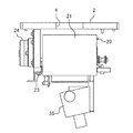
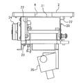
3次元造型機1は、開口4を開閉自在に覆うシャッター20を備えている。シャッター20は、開口4の面積よりも大きな表面積を有する遮蔽板21と(図3参照)、遮蔽板21の両側に位置する側板22とを有している。側板22は遮蔽板21に対して直交している。本実施形態では、遮蔽板21の上面は平面となっているが、遮蔽板21の上面は曲面であってもよい。遮蔽板21の形状は特に限定される訳ではない。側板22には、側方に突出する軸23が形成されている。図3に示すように、軸23はモータ24に連結されている。モータ24が軸23を回転させると、遮蔽板21が開口4を覆わない開位置(図1〜3参照)と、遮蔽板21が開口4を下方から覆う閉位置(図4〜6参照)との間で、シャッター20が移動する。シャッター20は、モータ24によって開閉される。
The three-
図1に示すように、側板22には側方に突出するピン25が形成されている。ピン25には、トーションばね26が引っ掛けられている。シャッター20はトーションばね26により、閉じる方向(図1の時計回り方向)の力を受けている。外部から力を加えない限り、シャッター20はトーションばね26の力により閉じた状態となる。なお、シャッター20を閉じる方向に付勢する手段は、トーションばね26に限定されない。上記手段は他の種類のばねであってもよく、ばね以外の付勢手段であってもよい。
As shown in FIG. 1, the
シャッター20の材料は何ら限定されず、例えば金属であってもよく、樹脂であってもよい。本実施形態では、シャッター20は鉄製であり、遮蔽板21および側板22は一体的に形成されている。ただし、シャッター20は複数の部品からなっていてもよい。シャッター20は、実質的に光を透過しない材料によって構成されている。そのため、台2の上に槽3を置いていないときに誤って光源11の電源がONされたとしても、光源11からの光が開口4を通じて外部に漏れ出すことは防止される。ただし、実質的に光を透過する材料でシャッター20を構成することも勿論可能である。
The material of the
3次元造型機1は、各種の制御を行う制御装置15を備えている。制御装置15は、光源11、鏡12を駆動するモータ(図示せず)、ホルダ8を昇降させるモータ7、およびシャッター20を駆動するモータ24を制御する。制御装置15は単一のコンピュータで構成されていてもよいが、複数のコンピュータによって構成されていてもよい。なお、ここでいうコンピュータは、マイクロコンピュータ等を含む意味である。
The three-
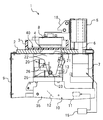
3次元造型機1の電源OFF時には、モータ24は駆動されず、シャッター20は閉じた状態となる。3次元造型機1を用いて3次元物体を生成する際には、電源をONする前またはONした後に、液体状の光硬化性樹脂40が収容された槽3を台2の上に載置する。この際、図5に示すようにシャッター20は開口4を塞いでいるので、たとえ槽3内の光硬化性樹脂40が台2の上に飛び散ったとしても、その樹脂40が開口4を通じてケース9内に入り込むことはなく、上記樹脂40がレンズ13等に付着してしまうことはない。
When the power of the three-
台2の上に槽3を載置した後、ユーザは図示しないスイッチを入力することにより、モータ24を駆動する。すると、図1に示すように、シャッター20が開かれる。ユーザが3次元造型機1の動作を開始させると、光源11から光が発せられる。光源11からの光は、鏡12に反射されかつレンズ13を通過した後、開口4を通過する。開口4を通過した光は、槽3の底板を通過し、底板とホルダ8との間に位置する光硬化性樹脂40に照射される。光を受けた光硬化性樹脂40は硬化する。鏡12の角度が適宜変更されることにより、光の照射位置が適宜変更され、光硬化性樹脂40によって、所望の断面形状を有する固体の樹脂の層が形成される。
After placing the
上記層が形成されると、モータ7が駆動され、ホルダ8は上方に移動する。すると、ホルダ8に保持された固体の樹脂層は引き上げられ、その樹脂層と槽3との間に隙間が形成され、この隙間に液体状の光硬化性樹脂40が流れ込む。そして、光源11からの光が上記隙間内の光硬化性樹脂40に照射され、所望の断面形状を有する次の固体樹脂層が形成される。以後、同様の動作が繰り返され、所望の3次元形状を有する物体が生成される。
When the above layer is formed, the
本実施形態に係る3次元造型機1によれば、台2の開口4を開閉自在に覆うシャッター20を備えている。台2の上に槽3を載置するまではシャッター20を閉じておくことにより、槽3内の液体状の光硬化性樹脂40が台2の上に飛び散ったとしても、上記樹脂40が開口4を通じてケース9の内部に入り込むことを防止することができる。よって、上記樹脂がレンズ13等に付着することを防止することができ、3次元造型機1の性能の低下を防ぐことができる。一方、3次元物体の生成の際にはシャッター20を開くことにより、光源11からの光を開口4を通じて、槽3内の光硬化性樹脂40に照射することができる。3次元造型機1によれば、開口4に透明なカバーが設けられている訳ではないので、開口4を通過する際の光の減衰を招くことなく、効率のよい3次元物体の生成が可能である。
According to the three-
本実施形態では、シャッター20は軸23を中心として水平軸周りに回転可能である。シャッター20は、回転式のシャッターである。しかし、シャッター20は回転式に限定されない。例えば、シャッター20は、水平方向にスライドするスライド式のシャッター等であってもよい。
In the present embodiment, the
ただし、シャッター20が回転式であれば、シャッター20を閉じているときに遮蔽板21に付着した樹脂は、シャッター20を開いたときに遮蔽板21から落下しやすくなり、円滑に排出されやすくなる。そのため、シャッター20が回転式であれば、遮蔽板21に付着した樹脂を円滑に除去しやすいという効果が期待できる。なお、シャッター20を開いたときの遮蔽板21の最下端部分の下方に、排出された樹脂を受けるトレイ等を設けるようにしてもよい。
However, if the
ユーザが誤って、槽3を台2の上に載せる前にシャッター20を開いてしまう可能性がある。また、ユーザが誤って、シャッター20が開いた状態のまま、槽3を台2の上から持ち上げてしまう可能性がある。そこで、槽3を台2の上に置かなければシャッター20が開かないようにするロック手段を設けるようにしてもよい。ロック手段の具体的構成は特に限定されず、例えば、フック等の機構を設けてもよく、制御装置15の制御によってロック手段を構築することも可能である。
There is a possibility that the user accidentally opens the
槽3が台2の上に載置されていることを検出する検出装置を設け、検出装置により台2の上に槽3が載置されていることが検出されると、ロック手段のロックを解除するようにしてもよい。上記検出装置の具体的構成は特に限定されず、従来から公知の各種の検出装置を利用することができる。
A detection device for detecting that the
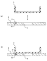
例えば図7(a)に示すように、台2に出没自在な突起31を設けるようにしてもよい。台2の上に槽3を載置していない場合には、突起31はばね32の力を受けて、台2から突出した状態となる。一方、図7(b)に示すように、台2の上に槽3を載置した場合、突起31は槽3の自重によって押し下げられ、台2に埋没した状態となる。したがって、突起31の状態に基づいて、槽3が台2の上に載置されているか否かを検出することができる。
For example, as shown in FIG. 7 (a), a
また、検出装置として、光学式センサ、接触式センサ等を用いることも勿論可能である。 Of course, an optical sensor, a contact sensor, or the like can be used as the detection device.
制御装置15は、台2の上に槽3が置かれているか否かに応じて、シャッター20を開閉させるモータ24を自動的に制御するように構成されていてもよい。制御装置15は、槽3が台2の上に載置されていることが上記検出装置により検出されないときには、シャッター20を閉じるようにモータ24を制御するように構成されていてもよい。この場合、制御装置15は、シャッター20を閉じた状態にロックし、槽3が台2の上に載置されるとロックを解除するロック手段として機能する。
The
また、上記制御装置15は、槽3が台2から離反するとシャッター20を閉じる自動閉鎖手段として機能する。これにより、シャッター20が開いているときに槽3を台2の上から持ち上げたとしても、シャッター20は直ちに自動的に閉じられる。そのため、ユーザが誤ってシャッター20を閉め忘れたまま槽3を台2の上から持ち上げたとしても、槽3内の光硬化性樹脂40が開口4を通じて光学装置10に付着することを防ぐことができる。
The
なお、シャッター20はトーションばね26によって、常に閉じる方向の付勢力を受けている。そのため、槽3が台2の上に載置されていることが上記検出装置により検出されないときには、モータ24への通電を停止するようにしてもよい。これにより、シャッター20はトーションばね26の付勢力により、自動的に閉じられる。
The
前記実施形態では、シャッター20はモータ24によって開閉されるように構成されていた。しかし、シャッター20は手動で開閉されるように構成されていてもよい。
In the embodiment, the
前記実施形態では、シャッター20の遮蔽板21は単一の部材により構成されていた。しかし、遮蔽板21は複数の部材から構成されていてもよい。例えば、開口4を開閉するシャッターは、互いに接近および離反する2枚のスライド板によって構成されていてもよい。シャッター20の構成は何ら限定されるものではない。
In the said embodiment, the shielding
1 3次元造型機
2 台
3 槽
4 開口
8 ホルダ
10 光学装置
11 光源
12 鏡
13 レンズ
15 制御装置(ロック手段、自動閉鎖手段)
20 シャッター
21 遮蔽板(遮蔽体)
23 軸
24 モータ(駆動装置)
26 トーションばね
40 光硬化性樹脂
1 Three-
20
23
26
Claims (7)
前記台の下方に配置され、少なくとも光を発する光源を有し、前記開口を通じて前記光源からの光を前記槽内の前記樹脂に照射する光学装置と、
前記光が照射されて硬化した前記樹脂を引き上げる昇降自在なホルダと、
前記開口を開閉自在に覆うシャッターと、
を備えた3次元造型機。 A base on which an opening is formed and on which a tank containing a liquid photocurable resin is placed;
An optical device disposed below the table, having a light source emitting at least light, and irradiating the resin in the tank with light from the light source through the opening;
A holder that can be raised and lowered to pull up the resin that has been irradiated with the light and cured;
A shutter that covers the opening so as to be freely opened and closed;
3D molding machine equipped with
前記駆動装置を制御する制御装置と、
前記槽が前記台上に載置されていることを検出する検出装置と、を備え、
前記ロック手段は、前記槽が前記台上に載置されていることが前記検出装置により検出されないと前記シャッターが開かないように前記駆動装置を制御する前記制御装置によって構成されている、請求項2に記載の3次元造型機。 A driving device for driving the shutter;
A control device for controlling the driving device;
A detection device for detecting that the tank is placed on the table,
The said lock | rock means is comprised by the said control apparatus which controls the said drive device so that the said shutter will not open, if it is not detected by the said detection apparatus that the said tank is mounted on the said table | surface. The three-dimensional molding machine according to 2.
前記駆動装置を制御する制御装置と、
前記槽が前記台上に載置されていることを検出する検出装置と、を備え、
前記自動閉鎖手段は、前記槽が前記台上に載置されていることが前記検出装置により検出されないと前記シャッターを閉じるように前記駆動装置を制御する前記制御装置によって構成されている、請求項4に記載の3次元造型機。 A driving device for driving the shutter;
A control device for controlling the driving device;
A detection device for detecting that the tank is placed on the table,
The said automatic closing means is comprised by the said control apparatus which controls the said drive device to close the said shutter, if it is not detected by the said detection apparatus that the said tank is mounted on the said table | surface. The three-dimensional molding machine according to 4.
The shutter rotates the shield between a shield having a surface area larger than the area of the opening, a closed position where the shield blocks the opening, and an open position where the shield does not block the opening. The three-dimensional molding machine according to any one of claims 1 to 4, further comprising a shaft that freely supports the shaft.
Priority Applications (1)
| Application Number | Priority Date | Filing Date | Title |
|---|---|---|---|
| JP2011053110A JP5689716B2 (en) | 2011-03-10 | 2011-03-10 | 3D molding machine |
Applications Claiming Priority (1)
| Application Number | Priority Date | Filing Date | Title |
|---|---|---|---|
| JP2011053110A JP5689716B2 (en) | 2011-03-10 | 2011-03-10 | 3D molding machine |
Publications (2)
| Publication Number | Publication Date |
|---|---|
| JP2012187807A true JP2012187807A (en) | 2012-10-04 |
| JP5689716B2 JP5689716B2 (en) | 2015-03-25 |
Family
ID=47081502
Family Applications (1)
| Application Number | Title | Priority Date | Filing Date |
|---|---|---|---|
| JP2011053110A Expired - Fee Related JP5689716B2 (en) | 2011-03-10 | 2011-03-10 | 3D molding machine |
Country Status (1)
| Country | Link |
|---|---|
| JP (1) | JP5689716B2 (en) |
Cited By (1)
| Publication number | Priority date | Publication date | Assignee | Title |
|---|---|---|---|---|
| CN104339656A (en) * | 2013-08-09 | 2015-02-11 | 罗兰Dg有限公司 | Three-dimensional printing apparatus |
-
2011
- 2011-03-10 JP JP2011053110A patent/JP5689716B2/en not_active Expired - Fee Related
Cited By (5)
| Publication number | Priority date | Publication date | Assignee | Title |
|---|---|---|---|---|
| CN104339656A (en) * | 2013-08-09 | 2015-02-11 | 罗兰Dg有限公司 | Three-dimensional printing apparatus |
| JP2015033826A (en) * | 2013-08-09 | 2015-02-19 | ローランドディー.ジー.株式会社 | 3D modeling equipment |
| EP2848393A1 (en) | 2013-08-09 | 2015-03-18 | Roland DG Corporation | Three-dimensional printing apparatus |
| US9409346B2 (en) | 2013-08-09 | 2016-08-09 | Roland Dg Corporation | Three-dimensional printing apparatus |
| CN104339656B (en) * | 2013-08-09 | 2018-09-25 | 罗兰Dg有限公司 | Three-dimensional moulding device |
Also Published As
| Publication number | Publication date |
|---|---|
| JP5689716B2 (en) | 2015-03-25 |
Similar Documents
| Publication | Publication Date | Title |
|---|---|---|
| JP6058502B2 (en) | 3D modeling equipment | |
| JP2017107242A5 (en) | ||
| JP6643438B2 (en) | Gaming machine | |
| JP5220138B2 (en) | Automatic liquid dispenser | |
| US10807309B2 (en) | Latching system for three dimensional print engine | |
| KR101715587B1 (en) | automatic tilted three-dimensional printer | |
| JP5689716B2 (en) | 3D molding machine | |
| JP2008286895A5 (en) | ||
| TW200740049A (en) | Electronic device and an enection device | |
| JP2011072470A (en) | Liftable shelf device | |
| JP5983595B2 (en) | Processing container and laser processing apparatus | |
| JP2008246014A (en) | Game machine | |
| CN205767555U (en) | A kind of solidification lamp box for 3D printed product | |
| JP2020521649A (en) | Three-dimensional printing system with improved light path | |
| US20240319390A1 (en) | Radiation image scanner | |
| JP2014226209A (en) | Photo-polymerization device | |
| KR102254748B1 (en) | 3D printing method and apparatus for printing objects by selectively using resin tanks | |
| JP2013183905A (en) | Game machine | |
| JP6687833B2 (en) | Amusement machine production equipment | |
| JP4749407B2 (en) | Gift acquisition game machine | |
| JP6736202B2 (en) | Amusement machine | |
| JP6736203B2 (en) | Amusement machine | |
| US20250187329A1 (en) | Recording device and control method of recording device | |
| JP6000304B2 (en) | Game machine | |
| CN201672329U (en) | Improved structure of ultraviolet light source device |
Legal Events
| Date | Code | Title | Description |
|---|---|---|---|
| A621 | Written request for application examination |
Free format text: JAPANESE INTERMEDIATE CODE: A621 Effective date: 20140130 |
|
| A977 | Report on retrieval |
Free format text: JAPANESE INTERMEDIATE CODE: A971007 Effective date: 20141218 |
|
| TRDD | Decision of grant or rejection written | ||
| A01 | Written decision to grant a patent or to grant a registration (utility model) |
Free format text: JAPANESE INTERMEDIATE CODE: A01 Effective date: 20150106 |
|
| A61 | First payment of annual fees (during grant procedure) |
Free format text: JAPANESE INTERMEDIATE CODE: A61 Effective date: 20150129 |
|
| R150 | Certificate of patent or registration of utility model |
Ref document number: 5689716 Country of ref document: JP Free format text: JAPANESE INTERMEDIATE CODE: R150 |
|
| R250 | Receipt of annual fees |
Free format text: JAPANESE INTERMEDIATE CODE: R250 |
|
| R250 | Receipt of annual fees |
Free format text: JAPANESE INTERMEDIATE CODE: R250 |
|
| R250 | Receipt of annual fees |
Free format text: JAPANESE INTERMEDIATE CODE: R250 |
|
| R250 | Receipt of annual fees |
Free format text: JAPANESE INTERMEDIATE CODE: R250 |
|
| R250 | Receipt of annual fees |
Free format text: JAPANESE INTERMEDIATE CODE: R250 |
|
| R250 | Receipt of annual fees |
Free format text: JAPANESE INTERMEDIATE CODE: R250 |
|
| R250 | Receipt of annual fees |
Free format text: JAPANESE INTERMEDIATE CODE: R250 |
|
| LAPS | Cancellation because of no payment of annual fees | ||
| S111 | Request for change of ownership or part of ownership |
Free format text: JAPANESE INTERMEDIATE CODE: R313111 |
|
| R360 | Written notification for declining of transfer of rights |
Free format text: JAPANESE INTERMEDIATE CODE: R360 |
|
| R360 | Written notification for declining of transfer of rights |
Free format text: JAPANESE INTERMEDIATE CODE: R360 |
|
| R371 | Transfer withdrawn |
Free format text: JAPANESE INTERMEDIATE CODE: R371 |