JP2012185230A - Erect life-size lens array plate, optical scanning unit, image reading device, and image writing device - Google Patents
Erect life-size lens array plate, optical scanning unit, image reading device, and image writing device Download PDFInfo
- Publication number
- JP2012185230A JP2012185230A JP2011046816A JP2011046816A JP2012185230A JP 2012185230 A JP2012185230 A JP 2012185230A JP 2011046816 A JP2011046816 A JP 2011046816A JP 2011046816 A JP2011046816 A JP 2011046816A JP 2012185230 A JP2012185230 A JP 2012185230A
- Authority
- JP
- Japan
- Prior art keywords
- lens array
- array plate
- light shielding
- lens
- shielding member
- Prior art date
- Legal status (The legal status is an assumption and is not a legal conclusion. Google has not performed a legal analysis and makes no representation as to the accuracy of the status listed.)
- Withdrawn
Links
Images


Classifications
-
- G—PHYSICS
- G02—OPTICS
- G02B—OPTICAL ELEMENTS, SYSTEMS OR APPARATUS
- G02B13/00—Optical objectives specially designed for the purposes specified below
- G02B13/24—Optical objectives specially designed for the purposes specified below for reproducing or copying at short object distances
- G02B13/26—Optical objectives specially designed for the purposes specified below for reproducing or copying at short object distances for reproducing with unit magnification
-
- G—PHYSICS
- G02—OPTICS
- G02B—OPTICAL ELEMENTS, SYSTEMS OR APPARATUS
- G02B3/00—Simple or compound lenses
- G02B3/0006—Arrays
- G02B3/0037—Arrays characterized by the distribution or form of lenses
- G02B3/0062—Stacked lens arrays, i.e. refractive surfaces arranged in at least two planes, without structurally separate optical elements in-between
-
- B—PERFORMING OPERATIONS; TRANSPORTING
- B41—PRINTING; LINING MACHINES; TYPEWRITERS; STAMPS
- B41J—TYPEWRITERS; SELECTIVE PRINTING MECHANISMS, i.e. MECHANISMS PRINTING OTHERWISE THAN FROM A FORME; CORRECTION OF TYPOGRAPHICAL ERRORS
- B41J2/00—Typewriters or selective printing mechanisms characterised by the printing or marking process for which they are designed
- B41J2/435—Typewriters or selective printing mechanisms characterised by the printing or marking process for which they are designed characterised by selective application of radiation to a printing material or impression-transfer material
- B41J2/447—Typewriters or selective printing mechanisms characterised by the printing or marking process for which they are designed characterised by selective application of radiation to a printing material or impression-transfer material using arrays of radiation sources
- B41J2/45—Typewriters or selective printing mechanisms characterised by the printing or marking process for which they are designed characterised by selective application of radiation to a printing material or impression-transfer material using arrays of radiation sources using light-emitting diode [LED] or laser arrays
-
- G—PHYSICS
- G02—OPTICS
- G02B—OPTICAL ELEMENTS, SYSTEMS OR APPARATUS
- G02B26/00—Optical devices or arrangements for the control of light using movable or deformable optical elements
- G02B26/08—Optical devices or arrangements for the control of light using movable or deformable optical elements for controlling the direction of light
- G02B26/10—Scanning systems
- G02B26/101—Scanning systems with both horizontal and vertical deflecting means, e.g. raster or XY scanners
Abstract
Description
本発明は、画像読取装置や画像書込装置に用いられる正立等倍レンズアレイプレートに関する。 The present invention relates to an erecting equal-magnification lens array plate used for an image reading apparatus and an image writing apparatus.
従来、スキャナ等の画像読取装置として、正立等倍結像光学系を用いた装置が知られている。正立等倍結像光学系を用いた場合、縮小結像光学系の場合よりも装置をコンパクトにすることができる。画像読取装置の場合、正立等倍結像光学系は、ライン状光源と、正立等倍レンズアレイと、ラインイメージセンサから構成される。 2. Description of the Related Art Conventionally, an apparatus using an erecting equal magnification imaging optical system is known as an image reading apparatus such as a scanner. When an erecting equal-magnification imaging optical system is used, the apparatus can be made more compact than in the case of a reduction imaging optical system. In the case of an image reading apparatus, the erecting equal-magnification imaging optical system includes a line light source, an erecting equal-magnification lens array, and a line image sensor.
正立等倍結像光学系における正立等倍レンズアレイとしては、正立等倍像を結像可能なロッドレンズアレイが用いられる。ロッドレンズアレイは、通常はレンズアレイの長手方向(画像読取装置の主走査方向)にロッドレンズが配列される。ロッドレンズの列数を増加することで、光量伝達率の向上、透過光量ムラの低減が図れるが、ロッドレンズアレイの場合、ロッドレンズの列数は、価格とのかねあいで1〜2列が一般的である。 As the erecting equal magnification lens array in the erecting equal magnification imaging optical system, a rod lens array capable of forming an erecting equal magnification image is used. In the rod lens array, rod lenses are usually arranged in the longitudinal direction of the lens array (main scanning direction of the image reading apparatus). Increasing the number of rows of rod lenses can improve the light transmission rate and reduce the amount of transmitted light, but in the case of a rod lens array, the number of rows of rod lenses is generally 1 to 2 depending on the price. Is.
一方、正立等倍レンズアレイとして、両面に複数の微小凸レンズを規則的に配列した透明な平板状レンズアレイプレートを、個々の凸レンズの光軸が一致するように2枚積層した正立等倍レンズアレイプレートも構成可能である。このような正立等倍レンズアレイプレートは、射出成形などの方法により形成できるため、正立等倍レンズアレイを比較的安価に製造することができる。 On the other hand, as an erecting equal-magnification lens array, an erecting equal-magnification obtained by laminating two transparent flat lens array plates regularly arranged with a plurality of minute convex lenses on both sides so that the optical axes of the individual convex lenses coincide with each other. A lens array plate can also be constructed. Since such an erecting equal-magnification lens array plate can be formed by a method such as injection molding, the erecting equal-magnification lens array can be manufactured at a relatively low cost.
正立等倍レンズアレイプレートでは、隣接したレンズ間に光を隔離するための壁が無いため、正立等倍レンズアレイプレートに斜めに入射した光が、プレート内部を斜めに進んで隣接した凸レンズに入り込み、出射してノイズ(ゴーストノイズともいう)を発生するという問題がある。 In an erecting equal-magnification lens array plate, there is no wall for isolating light between adjacent lenses, so light incident obliquely on the erecting equal-magnification lens array plate travels obliquely through the plate and is adjacent to the convex lens. There is a problem of entering and exiting to generate noise (also called ghost noise).
そこで、ゴーストノイズを低減するために、2枚のレンズアレイプレート間に遮光部材(以下、中間遮光部材と称する)を設けた正立等倍レンズアレイプレートが知られている(例えば、特許文献1参照)。 In order to reduce ghost noise, an erecting equal-magnification lens array plate in which a light shielding member (hereinafter referred to as an intermediate light shielding member) is provided between two lens array plates is known (for example, Patent Document 1). reference).
特許文献1に開示された正立等倍レンズアレイプレートにおいては、中間遮光部材は2枚のレンズアレイプレートにより挟み込まれている。言い換えると、2枚のレンズアレイプレートのレンズ間距離は、中間遮光部材の厚さによって規定されている。正立等倍レンズアレイプレートにおいては、所望の光学特性を実現するためにレンズ間距離は非常に重要である。従って、特許文献1に開示された正立等倍レンズアレイプレートの場合、中間遮光部材の厚さは正確に制御されなければならない。 In the erecting equal-magnification lens array plate disclosed in Patent Document 1, the intermediate light shielding member is sandwiched between two lens array plates. In other words, the distance between the lenses of the two lens array plates is defined by the thickness of the intermediate light shielding member. In an erecting equal-magnification lens array plate, the distance between lenses is very important in order to realize desired optical characteristics. Therefore, in the case of the erecting equal-magnification lens array plate disclosed in Patent Document 1, the thickness of the intermediate light shielding member must be accurately controlled.
中間遮光部材は、一般的に、例えば黒色のABS樹脂などの光吸収性材料を用いて、射出成形により形成される。中間遮光部材は、レンズアレイプレートの複数のレンズに対応する複数の開口部(貫通孔)を設けるために、貫通孔を形成するピン状の金型とこれを受ける金型を用いて形成される。しかしながら、実際の製造においては、ピン状の金型を用いるため、ピンに沿ったバリが貫通孔からレンズアレイプレートに対して垂直方向に発生しやすい(縦バリとも称される)。貫通孔に縦バリが発生すると、特許文献1のように中間遮光部材を2枚のレンズアレイプレートにより挟み込む構造の場合、貫通孔とレンズとの間にバリが挟まって隙間が生じ、光学特性に悪影響を与える可能性がある。バリを例えば研磨により削ればこの問題は解決できるが、このバリは非常に小さいので除去するのは容易ではない。また、除去できたとしても、このバリ除去行程分だけ製造コストが上昇する。 The intermediate light-shielding member is generally formed by injection molding using a light-absorbing material such as black ABS resin. The intermediate light shielding member is formed using a pin-shaped mold for forming a through hole and a mold for receiving the same in order to provide a plurality of openings (through holes) corresponding to the plurality of lenses of the lens array plate. . However, in actual manufacturing, since a pin-shaped mold is used, burrs along the pins are likely to occur in a direction perpendicular to the lens array plate from the through holes (also referred to as vertical burrs). When a vertical burr occurs in the through hole, as in Patent Document 1, in the structure in which the intermediate light shielding member is sandwiched between the two lens array plates, a burr is formed between the through hole and the lens, resulting in an optical characteristic. May have adverse effects. This problem can be solved if the burrs are shaved by polishing, for example, but the burrs are so small that they are not easy to remove. Even if it can be removed, the manufacturing cost increases by the amount of the deburring process.
本発明はこうした状況に鑑みてなされたものであり、その目的は、所望の光学特性を達成できる正立等倍レンズアレイプレート、並びに該正立等倍レンズアレイプレートを用いた光走査ユニット、画像読取装置および画像書込装置を提供することにある。 The present invention has been made in view of such circumstances, and an object thereof is an erecting equal-magnification lens array plate capable of achieving desired optical characteristics, an optical scanning unit using the erecting equal-magnification lens array plate, and an image. An object of the present invention is to provide a reading device and an image writing device.
上記課題を解決するために、本発明のある態様の正立等倍レンズアレイプレートは、両面に複数のレンズが形成された第1レンズアレイプレートと第2レンズアレイプレートとが対向するように配置された正立等倍レンズアレイプレートであって、第1レンズアレイプレートおよび/または第2レンズアレイプレートは、対向するレンズ間の距離を規定するためのレンズ間距離規定部を備える。 In order to solve the above-described problem, the erecting equal-magnification lens array plate according to an aspect of the present invention is disposed so that the first lens array plate and the second lens array plate in which a plurality of lenses are formed on both surfaces face each other. The first lens array plate and / or the second lens array plate includes an inter-lens distance defining unit for defining the distance between the facing lenses.
レンズ間距離規定部は、第1レンズアレイプレートおよび/または第2レンズアレイプレートと一体成形されていてもよい。 The inter-lens distance defining portion may be integrally formed with the first lens array plate and / or the second lens array plate.
レンズ間距離規定部は、第1レンズアレイプレートおよび/または第2レンズアレイプレートの対向面におけるレンズ部以外の部位から突出するように形成されていてもよい。 The inter-lens distance defining portion may be formed so as to protrude from a portion other than the lens portion on the facing surface of the first lens array plate and / or the second lens array plate.
レンズ間距離規定部は、当該レンズアレイプレートの主走査方向に延びるように形成されていてもよい。 The inter-lens distance defining portion may be formed to extend in the main scanning direction of the lens array plate.
第1レンズアレイプレートおよび第2レンズアレイプレートそれぞれにレンズ間距離規定部が形成されており、互いのレンズ間距離規定部同士が当接することで対向するレンズ間の距離が規定されてもよい。 An inter-lens distance defining portion may be formed on each of the first lens array plate and the second lens array plate, and the distance between the opposing lenses may be defined by contacting the inter-lens distance defining portions.
第1レンズアレイプレートと第2レンズアレイプレートは同一形状に形成されていてもよい。 The first lens array plate and the second lens array plate may be formed in the same shape.
第1レンズアレイプレートと第2レンズアレイプレートとの間に、それらの少なくとも一方から離間するよう設けられた中間遮光部材をさらに備えてもよい。 An intermediate light shielding member may be further provided between the first lens array plate and the second lens array plate so as to be separated from at least one of them.
本発明の別の態様もまた、正立等倍レンズアレイプレートである。この正立等倍レンズアレイプレートは、両面に複数のレンズが形成された第1レンズアレイプレートと第2レンズアレイプレートとが対向するように配置された正立等倍レンズアレイプレートであって、第2レンズアレイプレートの外側面を覆うように設けられた遮光部材をさらに備える。遮光部材は、第1レンズアレイプレートと第2レンズアレイプレートの対向するレンズ間の距離を規定するためのレンズ間距離規定部を備える。 Another embodiment of the present invention is also an erecting equal-magnification lens array plate. The erecting equal-magnification lens array plate is an erecting equal-magnification lens array plate arranged so that the first lens array plate and the second lens array plate, each having a plurality of lenses formed on both sides, are opposed to each other. A light shielding member is further provided to cover the outer surface of the second lens array plate. The light shielding member includes an inter-lens distance defining portion for defining a distance between the facing lenses of the first lens array plate and the second lens array plate.
遮光部材は、第2レンズアレイプレートの外側面を覆う遮光部と、遮光部から突出するように形成されたレンズ間距離規定部とを備えてもよい。第2レンズアレイプレートは、遮光部と当接することにより遮光部材との相対位置が規定され、第1レンズアレイプレートは、レンズ間距離規定部の先端部と当接することにより遮光部材との相対位置が規定されてもよい。 The light shielding member may include a light shielding part that covers the outer surface of the second lens array plate, and an inter-lens distance defining part that is formed so as to protrude from the light shielding part. The second lens array plate is in contact with the light shielding portion to define the relative position with the light shielding member, and the first lens array plate is in contact with the tip portion of the inter-lens distance defining portion to be relative to the light shielding member. May be defined.
第1レンズアレイプレートと第2レンズアレイプレートとの間に、それらの少なくとも一方から離間するよう設けられた中間遮光部材をさらに備えてもよい。 An intermediate light shielding member may be further provided between the first lens array plate and the second lens array plate so as to be separated from at least one of them.
遮光部材は、第2レンズアレイプレートの外側面を覆う遮光部と、遮光部から突出するように形成されたレンズ間距離規定部とを備えてもよい。第1レンズアレイプレートと第2レンズアレイプレートとの間に、第2レンズアレイプレートから離間するようレンズ間距離規定部により保持された中間遮光部材をさらに備えてもよい。第2レンズアレイプレートは、遮光部と当接することにより遮光部材との相対位置が規定され、第1レンズアレイプレートは、中間遮光部材と当接することにより遮光部材との相対位置が規定されてもよい。 The light shielding member may include a light shielding part that covers the outer surface of the second lens array plate, and an inter-lens distance defining part that is formed so as to protrude from the light shielding part. An intermediate light shielding member held by an inter-lens distance defining portion may be further provided between the first lens array plate and the second lens array plate so as to be separated from the second lens array plate. The relative position of the second lens array plate with the light shielding member is defined by contacting the light shielding portion, and the relative position of the first lens array plate with the light shielding member is defined by contacting with the intermediate light shielding member. Good.
本発明のさらに別の態様は、光走査ユニットである。この光走査ユニットは、被読取画像に光を照射するライン状光源と、被読取画像から反射した光を集光する上述の正立等倍レンズアレイプレートと、正立等倍レンズアレイプレートを透過した光を受光するラインイメージセンサとを備える。 Yet another embodiment of the present invention is an optical scanning unit. The optical scanning unit transmits the line-shaped light source that irradiates light to the read image, the above-described erecting equal-magnification lens array plate that collects the light reflected from the read image, and the erecting equal-magnification lens array plate. A line image sensor that receives the received light.
本発明のさらに別の態様は、画像読取装置である。この装置は、上述の光走査ユニットと、光走査ユニットによって検出された画像信号を処理する画像処理部と、を備える。 Yet another embodiment of the present invention is an image reading apparatus. This apparatus includes the above-described optical scanning unit and an image processing unit that processes an image signal detected by the optical scanning unit.
本発明のさらに別の態様は、画像書込装置である。この装置は、複数のLEDがアレイ状に配列されたLEDアレイと、LEDアレイから出射された光を集光する正立等倍レンズアレイプレートと、正立等倍レンズアレイプレートを透過した光を受光する感光体ドラムとを備える。 Yet another embodiment of the present invention is an image writing device. This device includes an LED array in which a plurality of LEDs are arranged in an array, an erecting equal-magnification lens array plate that collects light emitted from the LED array, and light transmitted through the erecting equal-magnification lens array plate. A photosensitive drum for receiving light.
なお、以上の構成要素の任意の組合せ、本発明の表現を方法、装置、システム、などの間で変換したものもまた、本発明の態様として有効である。 It should be noted that any combination of the above-described constituent elements and a representation obtained by converting the expression of the present invention between a method, an apparatus, a system, and the like are also effective as an aspect of the present invention.
本発明によれば、所望の光学特性を達成できる正立等倍レンズアレイプレート、並びに該正立等倍レンズアレイプレートを用いた光走査ユニット、画像読取装置および画像書込装置を提供できる。 According to the present invention, it is possible to provide an erecting equal-magnification lens array plate that can achieve desired optical characteristics, and an optical scanning unit, an image reading apparatus, and an image writing apparatus that use the erecting equal-magnification lens array plate.
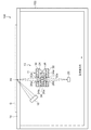
図1は、本発明の実施形態に係る画像読取装置100を説明するための図である。図1において、横方向が副走査方向であり、奥行き方向が主走査方向である。
FIG. 1 is a diagram for explaining an
図1に示すように、画像読取装置100は、筐体102、原稿Gを載置する原稿台としてのガラス板14、筐体102内に収容された光走査ユニット10、光走査ユニット10を走査する駆動機構(図示せず)、光走査ユニット10によって読み取られたデータを処理する画像処理部(図示せず)等を備える。
As shown in FIG. 1, the
光走査ユニット10は、ガラス板14上に載置された原稿Gに光を照射するライン状光源16と、原稿Gからの反射光を集光する正立等倍レンズアレイプレート11と、正立等倍レンズアレイプレート11により集光された光を受けるラインイメージセンサ(光電変換素子)20と、ライン状光源16、正立等倍レンズアレイプレート11およびラインイメージセンサ20を固定するケース(図示せず)とを備える。
The
ライン状光源16は、略直線状の光を出射する光源である。ライン状光源16は、その光軸が、正立等倍レンズアレイプレート11の光軸Axとガラス板14の上面との交点を通るように固定される。ライン状光源16から出射された光は、ガラス板14上に置かれた原稿Gに照射される。原稿Gに照射された光は、原稿Gにより正立等倍レンズアレイプレート11に向けて反射される。
The
正立等倍レンズアレイプレート11は、第1レンズアレイプレート24と第2レンズアレイプレート26とが対向するように配置されたものである。第1レンズアレイプレート24および第2レンズアレイプレート26は、長方形状のプレートであり、その両面には複数の凸レンズが配列形成されている。第1レンズアレイプレート24および第2レンズアレイプレート26は、ホルダ(図示せず)により保持されている。
The erecting equal-magnification
第1レンズアレイプレート24および第2レンズアレイプレート26は、射出成形により形成される。第1レンズアレイプレート24および第2レンズアレイプレート26の材質は、射出成形に使用可能で、必要な波長帯域の光に対して光透過性が高く、吸水性の低いものが望ましい。望ましい材質としては、シクロオレフィン系樹脂や、オレフィン系樹脂、ノルボルネン系樹脂、ポリカーボネートなどを例示することができる。
The first
第1レンズアレイプレート24の外側面(原稿側面)上には、複数の第1レンズ24aが、第1レンズアレイプレート24の長手方向(主走査方向)に沿って一列に配列されている。また、第1レンズアレイプレート24の内側面(第2レンズアレイプレート26と対向する面)上には、複数の第2レンズ24bが、第1レンズアレイプレート24の長手方向に沿って一列に配列されている。
A plurality of
第2レンズアレイプレート26の内側面(第1レンズアレイプレート24と対向する面)上には、複数の第3レンズ26aが、第2レンズアレイプレート26の長手方向(主走査方向)に沿って一列に配列されている。また、第2レンズアレイプレート26の外側面(ラインイメージセンサ側面)上には、複数の第4レンズ26bが、第2レンズアレイプレート26の長手方向に沿って一列に配列されている。
On the inner surface of the second lens array plate 26 (the surface facing the first lens array plate 24), a plurality of
第1レンズアレイプレート24と第2レンズアレイプレート26は、対応する第1レンズ24a、第2レンズ24b、第3レンズ26a、第4レンズ26bの組が共軸のレンズ系を構成するように内側面同士を対向させて積層される。言い換えると、第1レンズアレイプレート24と第2レンズアレイプレート26は、対応する第1レンズ24a、第2レンズ24b、第3レンズ26a、第4レンズ26bの光軸が一致するように積層される。
The first
第1レンズアレイプレート24の外側面上には、第1遮光部材30が設けられている。この第1遮光部材30は、遮光性材料によって形成されたプレート状の遮光部材であり、複数の第1貫通孔30aが形成されている。第1貫通孔30aは、第1遮光部材30の長手方向(主走査方向)に沿って一列に、第1レンズアレイプレート24の第1レンズ24aと対応するように形成されている。第1遮光部材30は、各第1貫通孔30aが対応する第1レンズ24aの正面に位置するように設けられる。
A first
第2レンズアレイプレート26の外側面上には、第2遮光部材32が設けられている。この第2遮光部材32もまた、遮光性材料によって形成されたプレート状の遮光部材であり、複数の第2貫通孔32aが形成されている。第2貫通孔32aは、第2遮光部材32の長手方向(主走査方向)に沿って一列に、第2レンズアレイプレート26の第4レンズ26bと対応するように形成されている。第2遮光部材32は、各第2貫通孔32aが対応する第4レンズ26bの正面に位置するように設けられる。
A second
第1レンズアレイプレート24と第2レンズアレイプレート26との間には中間遮光部材34が設けられている。この中間遮光部材34は、遮光性材料によって形成されたプレート状の遮光部材であり、複数の中間貫通孔34aが形成されている。中間貫通孔34aは、中間遮光部材34の長手方向(主走査方向)に沿って一列に、第2レンズ24bと第3レンズ26aと対応するように形成されている。中間遮光部材34は、各中間貫通孔34aが対応する第2レンズ24bおよび第3レンズ26aの正面に位置するように、第1レンズアレイプレート24と第2レンズアレイプレート26との間に設けられる。本実施形態においては、中間遮光部材34は、第1レンズアレイプレート24と第2レンズアレイプレート26の両方から離間して設けられている。言い換えると、中間遮光部材34は、第1レンズアレイプレート24と第2レンズアレイプレート26に接触していない。中間遮光部材34は、図示しないホルダにより保持されている。
An intermediate
第1遮光部材30、第2遮光部材32および中間遮光部材34は、例えば黒色のABS樹脂などの光吸収性材料を用いて、射出成形などの方法により形成することができる。第1遮光部材30、第2遮光部材32および中間遮光部材34は、正立等倍レンズアレイプレート11を斜めに通過する光を遮光し、ゴーストノイズを低減する機能を有する。
The first
以上のように構成された正立等倍レンズアレイプレート11は、その長手方向が主走査方向に、短手方向が副走査方向に一致するように画像読取装置100に装着される。
The erecting equal-magnification
正立等倍レンズアレイプレート11は、上方に位置する原稿Gから反射されたライン状の光を受けて、下方に位置する像面、すなわちラインイメージセンサ20の受光面に正立等倍像を形成する。画像読取装置100は、光走査ユニット10を副走査方向に走査することにより、原稿Gを読み取ることができる。
The erecting equal-magnification
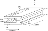
図2は、本実施形態に係る正立等倍レンズアレイプレート11の概略斜視図である。図2においては、第1レンズアレイプレート24と第2レンズアレイプレート26のみ図示しており、第1遮光部材30、第2遮光部材32および中間遮光部材34の図示を省略している。
FIG. 2 is a schematic perspective view of the erecting equal-magnification
図2に示すように、第1レンズアレイプレート24は、第2レンズアレイプレート26と対向する面における第2レンズ24b以外の部位から突出するように形成された第1レンズ間距離規定部24cを備える。また、第2レンズアレイプレート26は、第1レンズアレイプレート24と対向する面における第3レンズ26a以外の部位から突出するように形成された第2レンズ間距離規定部26cを備える。第1レンズ間距離規定部24cおよび第2レンズ間距離規定部26cは、対向する第2レンズ24bと第3レンズ26aとの間の距離D(以下、レンズ間距離Dとも称する)を規定するために設けられる。
As shown in FIG. 2, the first
第1レンズ間距離規定部24cおよび第2レンズ間距離規定部26cは、各レンズアレイプレートの長手方向(主走査方向)に延びるように形成されている。図2においては、各レンズ間距離規定部は、主走査方向に連続的に延びる突起部として形成されているが、断続的に形成されてもよい。また、第1レンズ間距離規定部24cおよび第2レンズ間距離規定部26cの先端は平坦面とされている。第1レンズ間距離規定部24cおよび第2レンズ間距離規定部26cは、それぞれ第1レンズアレイプレート24および第2レンズアレイプレート26と一体成形されている。
The first inter-lens
図2に示すように、正立等倍レンズアレイプレート11においては、第1レンズ間距離規定部24cの先端の平坦面と第2レンズ間距離規定部26cの先端の平坦面とが当接することで、レンズ間距離Dが規定される。中間遮光部材34はレンズ間距離Dの規定に関与していない。このように中間遮光部材34に代えて第1レンズ間距離規定部24cおよび第2レンズ間距離規定部26cを用いてレンズ間距離Dを規定することで、仮に中間遮光部材34の中間貫通孔34aにバリが発生しても、レンズ間距離Dの変動が生じにくくなる。
As shown in FIG. 2, in the erecting equal-magnification
レンズアレイプレートは、その寸法精度が光学特性に直接影響するので、元々正確な厚み制御が必要な部材である。本実施形態では、その厚みが正確に制御されたレンズアレイプレートにレンズ間距離を規定する機能を持たせることで、所望の(設計値通りの)レンズ間距離Dを達成できる。一方、中間遮光部材34にはそれほど高精度な厚み制御が要求されなくなるので、歩留まりを向上できる。また、バリの除去工程を省略できるので、製造コストを低減できる。
The lens array plate is a member that originally requires accurate thickness control because its dimensional accuracy directly affects the optical characteristics. In the present embodiment, a desired lens distance D (as designed) can be achieved by providing the lens array plate whose thickness is accurately controlled to have a function of defining the lens distance. On the other hand, since the intermediate
また、レンズアレイプレートや中間遮光部材を射出成形で製造する場合、レンズ間距離の設計を変更するときには成形用金型を修正する必要がある。このような場合、従来のように中間遮光部材を用いてレンズ間距離を規定する構成においては、比較的複雑な形状の中間遮光部材成形用金型を修正する必要があるので、レンズ間距離の設計変更は容易ではない。一方、本実施形態のようにレンズ間距離規定部を用いる構成においては、シンプルな形状のレンズ間距離規定部の高さを修正するだけでよいので、レンズ間距離の設計変更を容易に行うことができる。 Further, when the lens array plate and the intermediate light shielding member are manufactured by injection molding, it is necessary to modify the molding die when changing the design of the inter-lens distance. In such a case, in the conventional configuration in which the inter-lens distance is defined using the intermediate light shielding member, it is necessary to correct the intermediate light shielding member molding die having a relatively complicated shape. Design changes are not easy. On the other hand, in the configuration using the inter-lens distance defining portion as in the present embodiment, it is only necessary to modify the height of the simple lens-to-lens distance defining portion, so that the design of the inter-lens distance can be easily changed. Can do.
本実施形態においては、第1レンズアレイプレート24と第2レンズアレイプレート26は略同一形状に形成されている。この場合、別々の形状の2つのレンズアレイプレートを用意する必要がないので、部品コストを低減できる。
In the present embodiment, the first
しかしながら、第1レンズアレイプレート24と第2レンズアレイプレート26は異なる形状に形成されてもよい。例えば、本実施形態では、第1レンズアレイプレート24と第2レンズアレイプレート26の両方にレンズ間距離規定部を形成したが、いずれか一方のレンズアレイプレートにのみレンズ間距離規定部を形成し、他方のレンズアレイプレートに当接させてもよい。この場合も、上記と同様にレンズ間距離の精度を向上できる。
However, the first
本実施形態においては、第1レンズアレイプレート24と第2レンズアレイプレート26の両方から離間するよう中間遮光部材34を設けたが、少なくとも一方のレンズアレイプレートから離間するように設けられていればよい。言い換えると、中間遮光部材34が両方のレンズアレイプレートに接触していなければよい。これは、中間遮光部材34が両方のレンズアレイプレートに接触していると、中間遮光部材34のバリの影響を受けるおそれがあるためである。
In the present embodiment, the intermediate
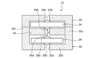
図3は、本発明の別の実施形態に係る正立等倍レンズアレイプレートを説明するための断面図である。図3において、横方向が副走査方向であり、奥行き方向が主走査方向である。 FIG. 3 is a cross-sectional view for explaining an erecting equal-magnification lens array plate according to another embodiment of the present invention. In FIG. 3, the horizontal direction is the sub-scanning direction, and the depth direction is the main scanning direction.
図3に示すように、本実施形態に係る正立等倍レンズアレイプレート11は、第1レンズアレイプレート24と、第2レンズアレイプレート26と、第1遮光部材30と、第2遮光部材32と、中間遮光部材34とを備える。各構成要素の基本的な機能は図1および図2に示す正立等倍レンズアレイプレートと同様である。本実施形態に係る正立等倍レンズアレイプレート11は、レンズ間距離Dを規定するための構造が図1および図2に示す正立等倍レンズアレイプレートと異なる。
As shown in FIG. 3, the erecting equal-magnification
本実施形態において、第2遮光部材32は、第2レンズアレイプレート26の外側面(ラインイメージセンサ側面)を覆う平板状の遮光部32bと、遮光部32bの副走査方向両端部から突出するように形成されたレンズ間距離規定部32cとを備える。遮光部32bとレンズ間距離規定部32cは一体成形されている。本実施形態においては、この第2遮光部材32に設けられたレンズ間距離規定部32cによって、レンズ間距離Dが規定される。
In the present embodiment, the second
図3に示すように、第2レンズアレイプレート26は、その外側面(ラインイメージセンサ側面)が第2遮光部材32の遮光部32bの内側面と当接することにより第2遮光部材32との相対位置が規定される。図3では第2レンズアレイプレート26の第4レンズ26bが遮光部32bと接触しているが、第2レンズアレイプレート26の外側面における第4レンズ26b以外の平坦部が遮光部32bと接触していてもよい。
As shown in FIG. 3, the second
一方、第1レンズアレイプレート24は、その内側面(第2レンズアレイプレート26と対向する面)がレンズ間距離規定部32cの先端部と当接することにより第2遮光部材32との相対位置が規定される。また、第1レンズアレイプレート24の外側面上には第1遮光部材30が設けられており、この第1遮光部材30と第2遮光部材32により第1レンズアレイプレート24が挟み込まれている。
On the other hand, the first
中間遮光部材34は、第1レンズアレイプレート24と第2レンズアレイプレート26の両方から離間して設けられている。つまり、中間遮光部材34は、第1レンズアレイプレート24と第2レンズアレイプレート26に接触していない。中間遮光部材34は、レンズ間距離規定部32cにより保持されている。
The intermediate
このように本実施形態においては、レンズ間距離Dは第2遮光部材32を基準として規定されている。中間遮光部材34はレンズ間距離Dの規定に関与していない。これにより、仮に中間遮光部材34の中間貫通孔34aにバリが発生しても、レンズ間距離Dの変動が生じにくくなる。なお、本実施形態においては、第2レンズアレイプレート26と遮光部32bとが当接する構造となっているが、第2貫通孔32aのバリが外側方向(ラインイメージセンサ方向)に出るように第2遮光部材32を製造すれば、バリにより第2レンズアレイプレート26が遮光部32bから浮き上がってレンズ間距離が変動する事態を回避できる。
Thus, in the present embodiment, the inter-lens distance D is defined with the second
また本実施形態においても、シンプルな形状のレンズ間距離規定部32cの高さを修正するだけでよいので、レンズ間距離の設計変更を容易に行うことができる。
Also in the present embodiment, it is only necessary to modify the height of the simple lens-to-lens
本実施形態においては、第1レンズアレイプレート24と第2レンズアレイプレート26の両方から離間するよう中間遮光部材34を設けたが、少なくとも一方のレンズアレイプレートから離間するように設けられていればよい。つまり、中間遮光部材34が両方のレンズアレイプレートに接触していなければよい。
In the present embodiment, the intermediate
図4は、本発明のさらに別の実施形態に係る正立等倍レンズアレイプレートを説明するための断面図である。図4において、横方向が副走査方向であり、奥行き方向が主走査方向である。 FIG. 4 is a cross-sectional view for explaining an erecting equal-magnification lens array plate according to still another embodiment of the present invention. In FIG. 4, the horizontal direction is the sub-scanning direction, and the depth direction is the main scanning direction.
図4に示すように、本実施形態に係る正立等倍レンズアレイプレート11は、第1レンズアレイプレート24と、第2レンズアレイプレート26と、第1遮光部材30と、第2遮光部材32と、中間遮光部材34とを備える。各構成要素の基本的な機能は図1および図2に示す正立等倍レンズアレイプレートと同様である。本実施形態に係る正立等倍レンズアレイプレート11は、レンズ間距離Dを規定するための構造が上述の正立等倍レンズアレイプレートと異なる。
As shown in FIG. 4, the erecting equal-magnification
本実施形態において、第2遮光部材32は、第2レンズアレイプレート26の外側面(ラインイメージセンサ側面)を覆う平板状の遮光部32bと、遮光部32bの副走査方向両端部から突出するように形成されたレンズ間距離規定部32cとを備える。遮光部32bとレンズ間距離規定部32cは一体成形されている。
In the present embodiment, the second
本実施形態において、中間遮光部材34は、第2レンズアレイプレート26から離間した状態で、第2遮光部材32のレンズ間距離規定部32cにより保持されている。
In the present embodiment, the intermediate
図4に示すように、第2レンズアレイプレート26は、その外側面が第2遮光部材32の遮光部32bの内側面と当接することにより第2遮光部材32との相対位置が規定される。図4では第2レンズアレイプレート26の第4レンズ26bが遮光部32bと接触しているが、第2レンズアレイプレート26の外側面における第4レンズ26b以外の平坦部が遮光部32bと接触していてもよい。
As shown in FIG. 4, the second
一方、第1レンズアレイプレート24は、その内側面が中間遮光部材34の上面(原稿側面)と当接することにより第2遮光部材32との相対位置が規定される。また、第1レンズアレイプレート24の外側面上には第1遮光部材30が設けられており、この第1遮光部材30と中間遮光部材34により第1レンズアレイプレート24が挟み込まれている。
On the other hand, the inner surface of the first
このように本実施形態においては、第2レンズアレイプレート26の位置は第2遮光部材32により規定され、第1レンズアレイプレート24の位置は中間遮光部材34を介して第2遮光部材32により規定されている。つまり、本実施形態におけるレンズ間距離Dもまた、第2遮光部材32を基準として規定されている。
Thus, in the present embodiment, the position of the second
本実施形態においては、中間遮光部材34と第1レンズアレイプレート24とが当接し、中間遮光部材34と第2レンズアレイプレート26とが離間する構造となっているため、中間貫通孔34aのバリが下方向(第2レンズアレイプレート方向)に出るように中間遮光部材34を製造すれば、バリによるレンズ間距離の変動を回避できる。
In the present embodiment, the intermediate
また本実施形態においては、第2遮光部材32による中間遮光部材34の保持位置を修正するだけでよいので、レンズ間距離の設計変更を容易に行うことができる。
Further, in the present embodiment, it is only necessary to correct the holding position of the intermediate
図5は、本発明の別の実施形態に係る画像書込装置200を説明するための図である。図5に示すように、画像書込装置200は、複数のLEDがアレイ状に配列されたLEDアレイ206と、LEDアレイ206が搭載された基板204と、LEDアレイ206を制御する制御部202と、LEDアレイ206から出射された光を集光する上述の正立等倍レンズアレイプレート11と、正立等倍レンズアレイプレート11を透過した光を受光する感光体ドラム208と、上記構成要素を収容する筐体210とを備える。なお、図5においては、感光体ドラム208の周辺に設けられる現像装置、転写装置などについては図示を省略している。図1に示す画像読取装置100の原稿Gを、画像書込装置200では感光体ドラム208に置き換え、更に、画像読取装置100のラインイメージセンサ20を画像書込装置200のLEDアレイ206に置き換えることで、画像読取装置100に関して説明した事項は、画像書き込み装置にも当てはまる。
FIG. 5 is a diagram for explaining an
画像書込装置200は、LEDを光源に用いた所謂LEDプリントヘッド方式の画像書込装置である。LEDプリントヘッド方式は、画素と発光源が1対1に対応しており、走査機構が不要である。従って、レーザ光源とポリゴンミラーを組み合わせたレーザROS(Raster Output Scanner)方式と比べて、装置を小型且つ軽量化できる。
The
従来、LEDプリントヘッド方式の正立等倍レンズアレイとしては、ロッドレンズアレイが用いられていたが、本発明に係る正立等倍レンズアレイプレート11を用いることにより、より安価な画像書込装置200を実現できる。また、本発明に係る正立等倍レンズアレイプレート11を用いることにより、所望の光学特性を実現できるので、良好な画像を感光体ドラム208上に形成できる。
Conventionally, a rod lens array has been used as an erecting equal-magnification lens array of the LED print head type. However, by using the erecting equal-magnification
以上、本発明を実施の形態をもとに説明した。この実施の形態は例示であり、それらの各構成要素や各処理プロセスの組合せにいろいろな変形例が可能なこと、またそうした変形例も本発明の範囲にあることは当業者に理解されるところである。 The present invention has been described based on the embodiments. This embodiment is an exemplification, and it will be understood by those skilled in the art that various modifications can be made to combinations of the respective constituent elements and processing processes, and such modifications are also within the scope of the present invention. is there.
10 光走査ユニット、 11 正立等倍レンズアレイプレート、 14 ガラス板、 16 ライン状光源、 20 ラインイメージセンサ、 24 第1レンズアレイプレート、 24c 第1レンズ間距離規定部、 26 第2レンズアレイプレート、 26c 第2レンズ間距離規定部、 30 第1遮光部材、 32 第2遮光部材、 32b 遮光部、 32c レンズ間距離規定部、 34 中間遮光部材、 34a 中間貫通孔、 100 画像読取装置、 200 画像書込装置、 202 制御部、 206 LEDアレイ、 208 感光体ドラム。 10 optical scanning unit, 11 erecting equal-magnification lens array plate, 14 glass plate, 16 line light source, 20 line image sensor, 24 first lens array plate, 24c first inter-lens distance defining portion, 26 second lens array plate , 26c second lens distance defining portion, 30 first light shielding member, 32 second light shielding member, 32b light shielding portion, 32c inter lens distance defining portion, 34 intermediate light shielding member, 34a intermediate through hole, 100 image reading device, 200 images Writing device, 202 control unit, 206 LED array, 208 photosensitive drum.
Claims (14)
前記第1レンズアレイプレートおよび/または前記第2レンズアレイプレートは、対向するレンズ間の距離を規定するためのレンズ間距離規定部を備えることを特徴とする正立等倍レンズアレイプレート。 An erecting equal-magnification lens array plate arranged so that a first lens array plate and a second lens array plate having a plurality of lenses formed on both sides face each other,
The first lens array plate and / or the second lens array plate is provided with an inter-lens distance defining portion for defining a distance between opposing lenses.
前記第2レンズアレイプレートの外側面を覆うように設けられた遮光部材をさらに備え、
前記遮光部材は、前記第1レンズアレイプレートと前記第2レンズアレイプレートの対向するレンズ間の距離を規定するためのレンズ間距離規定部を備えることを特徴とする正立等倍レンズアレイプレート。 An erecting equal-magnification lens array plate arranged so that a first lens array plate and a second lens array plate having a plurality of lenses formed on both sides face each other,
A light shielding member provided to cover an outer surface of the second lens array plate;
The erecting equal-magnification lens array plate, wherein the light shielding member includes an inter-lens distance defining portion for defining a distance between the facing lenses of the first lens array plate and the second lens array plate.
前記第2レンズアレイプレートは、前記遮光部と当接することにより前記遮光部材との相対位置が規定され、
前記第1レンズアレイプレートは、前記レンズ間距離規定部の先端部と当接することにより前記遮光部材との相対位置が規定されることを特徴とする請求項8に記載の正立等倍レンズアレイプレート。 The light shielding member includes a light shielding part that covers an outer surface of the second lens array plate, and the inter-lens distance defining part that is formed to protrude from the light shielding part,
The second lens array plate is in contact with the light shielding portion to define a relative position with the light shielding member,
9. The erecting equal-magnification lens array according to claim 8, wherein the first lens array plate has a relative position with respect to the light shielding member defined by abutting against a tip of the inter-lens distance defining portion. plate.
前記第1レンズアレイプレートと前記第2レンズアレイプレートとの間に、前記第2レンズアレイプレートから離間するよう前記レンズ間距離規定部により保持された中間遮光部材をさらに備え、
前記第2レンズアレイプレートは、前記遮光部と当接することにより前記遮光部材との相対位置が規定され、
前記第1レンズアレイプレートは、前記中間遮光部材と当接することにより前記遮光部材との相対位置が規定されることを特徴とする請求項8に記載の正立等倍レンズアレイプレート。 The light shielding member includes a light shielding part that covers an outer surface of the second lens array plate, and the inter-lens distance defining part that is formed to protrude from the light shielding part,
An intermediate light-shielding member held by the inter-lens distance defining portion so as to be separated from the second lens array plate between the first lens array plate and the second lens array plate;
The second lens array plate is in contact with the light shielding portion to define a relative position with the light shielding member,
9. The erecting equal-magnification lens array plate according to claim 8, wherein the first lens array plate is in contact with the intermediate light shielding member to define a relative position with respect to the light shielding member.
前記被読取画像から反射した光を集光する請求項1から11のいずれかに記載の正立等倍レンズアレイプレートと、
前記正立等倍レンズアレイプレートを透過した光を受光するラインイメージセンサと、
を備えることを特徴とする光走査ユニット。 A line-shaped light source for irradiating light on the read image;
The erecting equal-magnification lens array plate according to any one of claims 1 to 11, which collects light reflected from the read image;
A line image sensor that receives light transmitted through the erecting equal-magnification lens array plate;
An optical scanning unit comprising:
前記光走査ユニットによって検出された画像信号を処理する画像処理部と、
を備えることを特徴とする画像読取装置。 An optical scanning unit according to claim 12,
An image processing unit for processing an image signal detected by the optical scanning unit;
An image reading apparatus comprising:
前記LEDアレイから出射された光を集光する請求項1から11のいずれかに記載の正立等倍レンズアレイプレートと、
前記正立等倍レンズアレイプレートを透過した光を受光する感光体ドラムと、
を備えることを特徴とする画像書込装置。 An LED array in which a plurality of LEDs are arranged in an array;
The erecting equal-magnification lens array plate according to any one of claims 1 to 11, which collects light emitted from the LED array;
A photoconductive drum that receives light transmitted through the erecting equal-magnification lens array plate;
An image writing apparatus comprising:
Priority Applications (2)
| Application Number | Priority Date | Filing Date | Title |
|---|---|---|---|
| JP2011046816A JP2012185230A (en) | 2011-03-03 | 2011-03-03 | Erect life-size lens array plate, optical scanning unit, image reading device, and image writing device |
| US13/411,831 US8810912B2 (en) | 2011-03-03 | 2012-03-05 | Erecting equal-magnification lens array plate, optical scanning unit, image reading device, and image writing device |
Applications Claiming Priority (1)
| Application Number | Priority Date | Filing Date | Title |
|---|---|---|---|
| JP2011046816A JP2012185230A (en) | 2011-03-03 | 2011-03-03 | Erect life-size lens array plate, optical scanning unit, image reading device, and image writing device |
Publications (1)
| Publication Number | Publication Date |
|---|---|
| JP2012185230A true JP2012185230A (en) | 2012-09-27 |
Family
ID=46753134
Family Applications (1)
| Application Number | Title | Priority Date | Filing Date |
|---|---|---|---|
| JP2011046816A Withdrawn JP2012185230A (en) | 2011-03-03 | 2011-03-03 | Erect life-size lens array plate, optical scanning unit, image reading device, and image writing device |
Country Status (2)
| Country | Link |
|---|---|
| US (1) | US8810912B2 (en) |
| JP (1) | JP2012185230A (en) |
Cited By (2)
| Publication number | Priority date | Publication date | Assignee | Title |
|---|---|---|---|---|
| JP2015118357A (en) * | 2013-11-14 | 2015-06-25 | キヤノン株式会社 | Lens array optical system, image forming device having the same, and image reading device |
| JP2016186580A (en) * | 2015-03-27 | 2016-10-27 | キヤノン株式会社 | Lens array unit, image forming apparatus, and manufacturing method of lens array unit |
Families Citing this family (3)
| Publication number | Priority date | Publication date | Assignee | Title |
|---|---|---|---|---|
| JP2011119970A (en) * | 2009-12-03 | 2011-06-16 | Nippon Sheet Glass Co Ltd | Erecting equal-magnification lens array plate, optical scanning unit, and image reader |
| JP5863512B2 (en) * | 2012-02-29 | 2016-02-16 | 日本板硝子株式会社 | Lens array unit, erecting equal-magnification lens array, optical scanning unit, image reading device, and image writing device |
| JP5914422B2 (en) * | 2013-07-08 | 2016-05-11 | 京セラドキュメントソリューションズ株式会社 | Image reading apparatus and image forming apparatus |
Family Cites Families (3)
| Publication number | Priority date | Publication date | Assignee | Title |
|---|---|---|---|---|
| JP4950103B2 (en) | 2007-08-20 | 2012-06-13 | 日本板硝子株式会社 | Erecting equal-magnification lens array plate, image sensor unit and image reading apparatus |
| JP5243161B2 (en) * | 2008-09-18 | 2013-07-24 | 日本板硝子株式会社 | Image reading device |
| JP2011119970A (en) * | 2009-12-03 | 2011-06-16 | Nippon Sheet Glass Co Ltd | Erecting equal-magnification lens array plate, optical scanning unit, and image reader |
-
2011
- 2011-03-03 JP JP2011046816A patent/JP2012185230A/en not_active Withdrawn
-
2012
- 2012-03-05 US US13/411,831 patent/US8810912B2/en active Active
Cited By (2)
| Publication number | Priority date | Publication date | Assignee | Title |
|---|---|---|---|---|
| JP2015118357A (en) * | 2013-11-14 | 2015-06-25 | キヤノン株式会社 | Lens array optical system, image forming device having the same, and image reading device |
| JP2016186580A (en) * | 2015-03-27 | 2016-10-27 | キヤノン株式会社 | Lens array unit, image forming apparatus, and manufacturing method of lens array unit |
Also Published As
| Publication number | Publication date |
|---|---|
| US20120224242A1 (en) | 2012-09-06 |
| US8810912B2 (en) | 2014-08-19 |
Similar Documents
| Publication | Publication Date | Title |
|---|---|---|
| JP5863512B2 (en) | Lens array unit, erecting equal-magnification lens array, optical scanning unit, image reading device, and image writing device | |
| JP5802408B2 (en) | Erecting equal-magnification lens array plate, optical scanning unit, image reading device, and image writing device | |
| JP5466456B2 (en) | Erecting equal-magnification lens array plate, optical scanning unit, and image reading apparatus | |
| JP2012163850A (en) | Erecting equal-magnification lens array plate, optical scanning unit, image reading device, and image writing system | |
| US8947747B2 (en) | Erecting equal-magnification lens array plate and image reading device | |
| JP2013037298A (en) | Erecting life-size lens array plate | |
| JP2010224164A (en) | Erect equal magnification lens array plate, optical scanning unit, and image reading device | |
| JP2012185230A (en) | Erect life-size lens array plate, optical scanning unit, image reading device, and image writing device | |
| KR20080088222A (en) | Image forming apparatus and laser scanning unit and polygon mirror thereof | |
| JP2010286741A (en) | Erecting unit magnification lens array plate, optical scanning unit and image reader | |
| JP5918938B2 (en) | Lens array plate and erecting equal-magnification lens array plate manufacturing method | |
| JP5802405B2 (en) | Erecting equal-magnification lens array plate, optical scanning unit, image reading device, and image writing device | |
| JP2018152713A (en) | Image reader | |
| JP6102091B2 (en) | Image reading device | |
| JP2011118122A (en) | Erecting equal magnification lens array plate, optical scanning unit and image reading apparatus | |
| JP2011119970A (en) | Erecting equal-magnification lens array plate, optical scanning unit, and image reader | |
| US9417447B2 (en) | Rod lens array and image sensor | |
| WO2011004593A1 (en) | Erecting same-size lens array plate, optical scan unit, image reader, and method for manufacturing erecting same-size lens array plate | |
| JP2020160239A (en) | Optical device, image reading device, and image forming apparatus | |
| JP6112977B2 (en) | Rod lens array and image sensor | |
| JP5889684B2 (en) | Erecting equal-magnification lens array unit and image reading apparatus | |
| US10136019B2 (en) | Illumination apparatus, sensor unit, and reading apparatus | |
| JP2013228625A (en) | Erect equal magnification lens array, optical scanning unit, image reader, and image writing device | |
| JP2010210716A (en) | Lens unit, lens assembly member, led head, exposure device, image forming apparatus, reader, and method for manufacturing the lens assembly member | |
| JP2008067340A (en) | Image sensor and image transmission module |
Legal Events
| Date | Code | Title | Description |
|---|---|---|---|
| A300 | Application deemed to be withdrawn because no request for examination was validly filed |
Free format text: JAPANESE INTERMEDIATE CODE: A300 Effective date: 20140513 |