JP2012184021A - Packaging bag and method for packing the same - Google Patents
Packaging bag and method for packing the same Download PDFInfo
- Publication number
- JP2012184021A JP2012184021A JP2011048154A JP2011048154A JP2012184021A JP 2012184021 A JP2012184021 A JP 2012184021A JP 2011048154 A JP2011048154 A JP 2011048154A JP 2011048154 A JP2011048154 A JP 2011048154A JP 2012184021 A JP2012184021 A JP 2012184021A
- Authority
- JP
- Japan
- Prior art keywords
- sheet
- inner lid
- bag
- bag body
- packaging bag
- Prior art date
- Legal status (The legal status is an assumption and is not a legal conclusion. Google has not performed a legal analysis and makes no representation as to the accuracy of the status listed.)
- Granted
Links
- 238000004806 packaging method and process Methods 0.000 title claims abstract description 87
- 238000000034 method Methods 0.000 title claims description 24
- 238000012856 packing Methods 0.000 title abstract description 5
- 239000000463 material Substances 0.000 claims abstract description 32
- 239000000853 adhesive Substances 0.000 claims description 36
- 230000001070 adhesive effect Effects 0.000 claims description 36
- 238000000605 extraction Methods 0.000 claims description 12
- 239000000945 filler Substances 0.000 claims description 10
- 230000003014 reinforcing effect Effects 0.000 claims description 6
- 238000003466 welding Methods 0.000 abstract description 50
- 239000010410 layer Substances 0.000 description 32
- 229920005989 resin Polymers 0.000 description 18
- 239000011347 resin Substances 0.000 description 18
- 230000015572 biosynthetic process Effects 0.000 description 6
- 230000008569 process Effects 0.000 description 6
- 238000004519 manufacturing process Methods 0.000 description 5
- 238000002844 melting Methods 0.000 description 5
- 229920003023 plastic Polymers 0.000 description 5
- 239000004033 plastic Substances 0.000 description 5
- 230000008018 melting Effects 0.000 description 4
- 239000000843 powder Substances 0.000 description 4
- 230000001105 regulatory effect Effects 0.000 description 4
- 238000005520 cutting process Methods 0.000 description 3
- 241000209140 Triticum Species 0.000 description 2
- 235000021307 Triticum Nutrition 0.000 description 2
- 230000008859 change Effects 0.000 description 2
- 235000013351 cheese Nutrition 0.000 description 2
- 239000000428 dust Substances 0.000 description 2
- 230000000694 effects Effects 0.000 description 2
- 238000005429 filling process Methods 0.000 description 2
- 235000013312 flour Nutrition 0.000 description 2
- 239000011521 glass Substances 0.000 description 2
- 230000001771 impaired effect Effects 0.000 description 2
- 239000002184 metal Substances 0.000 description 2
- -1 polyethylene, ethylene-vinyl acetate Polymers 0.000 description 2
- 230000002787 reinforcement Effects 0.000 description 2
- 150000003839 salts Chemical class 0.000 description 2
- 235000002639 sodium chloride Nutrition 0.000 description 2
- 238000003860 storage Methods 0.000 description 2
- 239000000126 substance Substances 0.000 description 2
- 239000002699 waste material Substances 0.000 description 2
- 229920010126 Linear Low Density Polyethylene (LLDPE) Polymers 0.000 description 1
- 235000015429 Mirabilis expansa Nutrition 0.000 description 1
- 244000294411 Mirabilis expansa Species 0.000 description 1
- 239000004952 Polyamide Substances 0.000 description 1
- 239000004743 Polypropylene Substances 0.000 description 1
- 238000005452 bending Methods 0.000 description 1
- 229920001577 copolymer Polymers 0.000 description 1
- 239000003599 detergent Substances 0.000 description 1
- 239000005038 ethylene vinyl acetate Substances 0.000 description 1
- 230000004927 fusion Effects 0.000 description 1
- 238000010438 heat treatment Methods 0.000 description 1
- 239000012793 heat-sealing layer Substances 0.000 description 1
- 235000015110 jellies Nutrition 0.000 description 1
- 239000008274 jelly Substances 0.000 description 1
- 239000007788 liquid Substances 0.000 description 1
- 235000013536 miso Nutrition 0.000 description 1
- 230000004048 modification Effects 0.000 description 1
- 238000012986 modification Methods 0.000 description 1
- 239000002245 particle Substances 0.000 description 1
- 229920002647 polyamide Polymers 0.000 description 1
- 229920000728 polyester Polymers 0.000 description 1
- 229920001155 polypropylene Polymers 0.000 description 1
- 238000003825 pressing Methods 0.000 description 1
- 230000009467 reduction Effects 0.000 description 1
- 238000007789 sealing Methods 0.000 description 1
- 239000002356 single layer Substances 0.000 description 1
- 235000014214 soft drink Nutrition 0.000 description 1
- 229920002554 vinyl polymer Polymers 0.000 description 1
Images


Classifications
-
- B—PERFORMING OPERATIONS; TRANSPORTING
- B31—MAKING ARTICLES OF PAPER, CARDBOARD OR MATERIAL WORKED IN A MANNER ANALOGOUS TO PAPER; WORKING PAPER, CARDBOARD OR MATERIAL WORKED IN A MANNER ANALOGOUS TO PAPER
- B31B—MAKING CONTAINERS OF PAPER, CARDBOARD OR MATERIAL WORKED IN A MANNER ANALOGOUS TO PAPER
- B31B70/00—Making flexible containers, e.g. envelopes or bags
- B31B70/74—Auxiliary operations
- B31B70/81—Forming or attaching accessories, e.g. opening devices, closures or tear strings
- B31B70/84—Forming or attaching means for filling or dispensing contents, e.g. valves or spouts
- B31B70/85—Applying patches or flexible valve inserts, e.g. applying film-like valves
Abstract
Description
本発明は、シート材から形成される包装袋、及びその包装袋に対する充填方法に関する。 The present invention relates to a packaging bag formed from a sheet material and a filling method for the packaging bag.
近年、プラスチックボトルやガラス瓶等のボトル容器に代えて、樹脂シートを袋状に形成した包装袋が容器として使用されている。この種のシート材から形成される包装袋は、プラスチックボトルやガラス瓶等のボトル容器に比べて省資源化が可能であり、また使用後に小さく折り畳むことができるため、ごみの減容化にも寄与する。 In recent years, instead of bottle containers such as plastic bottles and glass bottles, packaging bags in which resin sheets are formed in a bag shape have been used as containers. Packaging bags made of this type of sheet material can save resources compared to bottle containers such as plastic bottles and glass bottles, and can be folded down after use, contributing to the reduction of waste volume. To do.
ところで、粉チーズ、食塩、小麦粉等の粉粒体用の容器として上記包装袋を適用する際、充填物である粉粒体が一度に多量に振り出されることを防止するために、袋口にプラスチック製の振出用キャップが取り付けられる場合がある。こうした振出用キャップとしては、例えば特許文献1に開示されるものが知られている。特許文献1の振出用キャップは、筒状の基体と、基体の上部開口を塞ぐ複数の取出孔が形成された内蓋と、内蓋の取出孔を塞ぐ外蓋とから構成されるものである。この振出用キャップを取り付けた包装袋は、振出用キャップの外蓋のみを開いた状態とすることにより、粉粒体の振出量を規制しつつ、内蓋に形成された取出孔から少量ずつ粉粒体を振り出すことができる。
By the way, when applying the packaging bag as a container for powdered cheese, salt, wheat flour, etc., in order to prevent a large amount of powdered powders from being swung out at once, A plastic swing cap may be attached. As such a swing cap, for example, a cap disclosed in
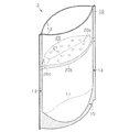
しかしながら、包装袋に対してプラスチック製の振出用キャップを取り付けた場合には、省資源化やごみの減容化ができるという包装袋を用いることによる利点が損なわれてしまう。そこで、本発明者らは図5に示すように、プラスチック製の振出用キャップに代えて、取出孔を有するシート材から形成された内蓋シートを備える包装袋を開発した。ところが、こうした内蓋シートを備える包装袋では、内部に充填物を充填する充填作業が困難になるという問題があった。 However, when a plastic ejecting cap is attached to the packaging bag, the advantages of using the packaging bag that can save resources and reduce the volume of waste are impaired. Therefore, the present inventors have developed a packaging bag including an inner lid sheet formed of a sheet material having an extraction hole, instead of a plastic cap for ejection as shown in FIG. However, the packaging bag provided with such an inner lid sheet has a problem that it is difficult to fill the inside with a filling material.
すなわち、内蓋シートを備える包装袋においては内蓋シートの下部が充填物の収容部分となるが、この収容部分に充填物を充填するためには、内蓋シートに形成された取出孔を通じて充填しなければならない。そのため、少量ずつしか充填することができず、充填作業に多大な時間がかかる。ここで、充填作業を素早く行うために、内蓋シートの取出孔を大きくする、或いは充填ノズルを挿入可能な程度の大きさの充填孔を取出孔とは別に内蓋シートに設けるといった方法も考えられる。しかしながら、これらの場合には、取出量を規制するという内蓋シートの機能が損なわれるおそれがある。さらに、内蓋シートを取り付けていない包装袋に対して充填物を充填し、充填後に内蓋シートを取り付けるという方法も試みた。しかしながら、包装袋及び内蓋シートが共に可撓性を有し、屈曲しやすいために、充填物が充填されて膨張した包装袋内の特定位置に内蓋シートを位置決めしつつ、内蓋シートの縁部を包装袋の内面に接着することは困難な作業であった。 That is, in a packaging bag having an inner lid sheet, the lower part of the inner lid sheet is a storage portion for the filling material. In order to fill the storage portion with the filling material, filling is performed through an extraction hole formed in the inner lid sheet. Must. Therefore, it can be filled only in small amounts, and the filling work takes a lot of time. Here, in order to perform the filling operation quickly, a method of enlarging the take-out hole of the inner lid sheet or providing a fill hole of a size that can be inserted with the filling nozzle in the inner lid sheet is also considered. It is done. However, in these cases, there is a possibility that the function of the inner lid sheet for regulating the removal amount is impaired. Furthermore, a method of filling the packing bag without the inner lid sheet with the filling material and attaching the inner lid sheet after filling was also attempted. However, since both the packaging bag and the inner lid sheet have flexibility and are easy to bend, the inner lid sheet is positioned at a specific position in the packaging bag filled with the filler and inflated. Adhering the edge to the inner surface of the packaging bag was a difficult task.
この発明は、こうした従来の実情に鑑みてなされたものであり、その目的は、シート材からなる内蓋を有する包装袋であって、省資源化やごみの減容化ができるとともに、充填作業を容易に行うことのできる包装袋を提供することにある。また、そうした包装袋に対する充填方法を提供することにある。 The present invention has been made in view of such conventional circumstances, and an object thereof is a packaging bag having an inner lid made of a sheet material, which can save resources and reduce the volume of dust, and can be used for filling work. It is an object of the present invention to provide a packaging bag that can be easily performed. Moreover, it is providing the filling method with respect to such a packaging bag.
上記の目的を達成するために請求項1に記載の包装袋は、シート材により上辺部分を開口可能な袋状に形成された袋本体と、該袋本体内に取り付けられ、複数の取出孔を有するシート材からなる内蓋シートとを備え、前記袋本体の左辺及び右辺には、同袋本体の側面を形成する一対の側面シート同士を接着してなる左辺接着領域及び右辺接着領域が設けられ、前記内蓋シートは、上下二つ折りにされた状態で前記袋本体内に配置されるとともに、その折辺方向の両端に設けられる端部接着部が、前記袋本体の左辺接着領域及び右辺接着領域にて前記一対の側面シートと共に接着されており、二つ折りにされた前記内蓋シートにおける少なくとも一方側の外面を前記側面シートに対して未接着とすることにより、前記内蓋シートの外面と前記側面シートとの間を離間可能に構成したことを特徴とする。
In order to achieve the above object, a packaging bag according to
請求項1に記載の包装袋では、樹脂シート等のシート材からなる内蓋シートを上下二つ折りにした状態で袋本体の側面シート間に挟み込み、内蓋シートの折辺方向の両端に設けられた端部接着部を、袋本体の左辺接着領域及び右辺接着領域にて側面シートと共に接着することによって、袋本体内に内蓋シートを固定している。一方、二つ折りにされた内蓋シートの外面の少なくとも一方については、側面シートに対して未接着とし、内蓋シートの外面と側面シートとの間を離間可能に構成している。
In the packaging bag according to
これにより、充填物を充填する際に、充填ノズルを内蓋シートの外面と側面シートの内面との間に挿入することが可能となる。そのため、袋本体内における内蓋シートの下部に位置する収容部内へ充填ノズルから充填物を直接充填することが可能となり、充填作業を素早く行うことができるようになる。 Thereby, when filling a filling material, it becomes possible to insert a filling nozzle between the outer surface of the inner lid sheet and the inner surface of the side sheet. Therefore, it becomes possible to directly fill the filling portion from the filling nozzle into the accommodating portion located in the lower portion of the inner lid sheet in the bag body, and the filling operation can be performed quickly.
また、充填物の充填後において、互いに離間可能に構成されていた内蓋シートと側面シートとが接着されることにより、内蓋シートは充填物の取出量を規制するための内蓋として機能するようになる。このとき、内蓋シートは、端部接着部が袋本体の左辺接着領域及び右辺接着領域に接着されて、既に袋本体内の所定位置に位置決めされた状態にあるため、内蓋シートの外面と側面シートとの接着を容易に行うことができる。 Further, the inner lid sheet and the side sheet, which are configured to be separated from each other after the filling of the filler, are bonded to each other, so that the inner lid sheet functions as an inner lid for regulating the amount of the filler taken out. It becomes like this. At this time, the inner lid sheet is in a state in which the end adhesive portion is bonded to the left side adhesive region and the right side adhesive region of the bag body and is already positioned at a predetermined position in the bag body. Adhesion with the side sheet can be easily performed.
請求項2に記載の包装袋は、請求項1に記載の発明において、前記袋本体における前記内蓋シートの端部接着部との接着部分の上部に、開口状態を維持するための補強部材が取り付けられていることを特徴とする。上記構成によれば、補強部材によって開口状態が維持されることにより、取出孔を介して内蓋シートを通過した充填物をより確実に袋外に取り出すことができる。
The packaging bag according to
請求項3に記載の充填方法は、請求項1又は請求項2に記載の包装袋に対する充填方法であって、前記袋本体の上辺部分を開口させるとともに、前記内蓋シートの外面と前記側面シートとを離間させる開口工程と、前記内蓋シートの外面と前記側面シートと間の隙間を通じて、前記包装袋内に充填物を充填する充填工程と、前記内蓋シートの外面と前記側面シートとを接着する接着工程とを有することを特徴とする。上記構成によれば、請求項1〜請求項3のいずれか一項に記載の包装袋に対して充填物を容易に充填することができる。
The filling method according to claim 3 is a filling method for the packaging bag according to
本発明の包装袋、及びその包装袋に対する充填方法によれば、省資源化やごみの減容化ができるとともに、充填作業を容易に行うことができる。 According to the packaging bag and the filling method for the packaging bag of the present invention, it is possible to save resources and reduce the volume of dust, and to perform filling work easily.
以下、本発明の包装袋1を図面に基づいて説明する。
図1に示すように、本実施形態の包装袋1は、複数のシート材からなる袋状の袋本体10と、袋本体10の内部に取り付けられ、同じくシート材からなる内蓋シート20とを備えている。この袋本体10を構成するシート材及び内蓋シート20を構成するシート材としては、包装袋に一般的に用いられる公知の樹脂シート(例えば、ポリエチレン、エチレン−酢酸ビニル共重合体、エチレン−ビニルアルコール共重合体、ポリアミド、及びポリエステル等からなる単層又は多層の樹脂シート)を用いることができる。本実施形態では、袋本体10を構成するシート材として、一方側の表面のみに熱溶着性樹脂からなる熱溶着層を有する樹脂シートを用いている。そして、内蓋シート20を構成するシート材として、両側の表面に熱溶着性樹脂からなる熱溶着層を有する樹脂シートを用いている。
Hereinafter, the
As shown in FIG. 1, the
まず、袋本体10について説明する。図2に示すように、袋本体10は、折り目が上方を向くように二つ折りにされた横長長方形状の底面シート11と、その底面シート11を挟み込むように対向配置された一対の縦長長方形状の側面シート12とから構成されている。底面シート11は熱溶着層を有する側の面が外側を向くようにして二つ折りにされる。また、一対の側面シート12は熱溶着層を有する側の面を互いに向かい合わせるようにして対向配置される。
First, the
図1(b)に示すように、袋本体10は、底面シート11を挟んで一対の側面シート12を重ね合わせた状態とされ、その左辺部分、右辺部分及び下辺部分がそれぞれ熱溶着されることにより、上辺部分を開口可能な袋状に形成されている。具体的には、袋本体10の左辺及び右辺においては、側面シート12の内面同士が左辺及び右辺に沿って一定幅で熱溶着されており、この熱溶着部分がそれぞれ左辺接着領域13及び右辺接着領域14となる。
As shown in FIG.1 (b), the bag
一方、袋本体10の下辺においては、側面シート12の内面と底面シート11の外面とが熱溶着され、この熱溶着領域が下辺接着領域15となる。この下辺接着領域15は、上下方向において円弧状に凹んだ曲線と側面シート12の左縁、右縁及び下縁とによって囲まれた領域となるように形成されている。また、袋本体10の左辺接着領域13及び右辺接着領域14には、U字状に切り欠かれた切取溝16がそれぞれ形成されている。
On the other hand, at the lower side of the
次に、内蓋シート20について説明する。図3に示すように、内蓋シート20は横長長方形状に形成されたシート材であり、その中央部分には複数の取出孔21が貫通形成されている。内蓋シート20の短辺側の側縁である短側縁20aの両端部には、長辺側の側縁である長側縁20bに沿って長手方向に突出する一対の端部接着部22がそれぞれ設けられている。内蓋シート20の長さ寸法L1(端部接着部22の先端間の距離)は、袋本体10の幅(左右方向の長さ)に等しくなるように設定されている。また、端部接着部22の突出長L2は、袋本体10の左辺接着領域13及び右辺接着領域14の幅に等しくなるように設定されている。
Next, the
また、上で述べたとおり、内蓋シート20には両側の表面に熱溶着層を有する樹脂シートを用いているが、内蓋シート20の一方側の表面である第1面(図3における紙面表側の面)には、熱溶着層のない非熱溶着部23が部分的に設けられている。この非熱溶着部23は、長側縁20bから所定幅の範囲で一方側の端部接着部22の基端から他方側の端部接着部22の基端まで形成されている。
Further, as described above, the
図2に示すように、内蓋シート20は、上記第1面を内側とし、一対の長側縁20bを重ねるようにして上下に二つ折りし、その折辺24を上側に向けた状態で、袋本体10の左右方向に延びるようにして側面シート12間に挟みこまれている。そして、二つ折りにされた内蓋シート20の左右に突出する端部接着部22は、二重に重ねられた状態で、袋本体10の左辺接着領域13及び右辺接着領域14内にて、側面シート12の左辺部分及び右辺部分と共に一体に熱溶着されている(図1(b)参照)。つまり、端部接着部22の外面と側面シート12の内面とが熱溶着されるとともに、端部接着部22の内面同士が熱溶着されている。一方、二つ折りにされた内蓋シート20の両外面は、(端部接着部22部分を除いて)袋本体10の側面シート12に対して未接着となっている。したがって、内蓋シート20は、折辺24方向の両端に位置する端部接着部22のみが袋本体10に接着された状態で袋本体10内に取り付けられている。
As shown in FIG. 2, the
袋本体10に対する上下方向における内蓋シート20の取付位置は、袋本体10の中央部より上辺側であって、且つ内蓋シート20の折辺24と袋本体10の上辺との間に所定の間隔が形成される位置となっている。なお、袋本体10における切取溝16の形成位置は、内蓋シート20の折辺24よりも上辺側となっている。
The attachment position of the
次に、包装袋1を製造する方法について説明する。
まず、一方側の表面のみに熱溶着層を有する樹脂シートからなり、底面シート11を形成する帯状の第1シートを用意し、この第1シートを上下に二つ折りの状態とする。また、両方の表面に熱溶着層を有する樹脂シートからなり、内蓋シート20を形成する帯状の第2シートを用意し、この第2シートも同様に上下に二つ折りの状態とする。そして、二つ折りにした第1シート及び第2シートを、各折辺が共に上方を向くように向きを揃えた状態で並列に配置する。
Next, a method for manufacturing the
First, a belt-like first sheet made of a resin sheet having a heat-welded layer only on one surface and forming the
ここで、底面シート11を形成する帯状の第1シートは、熱溶着層を有する側の面が外側を向くように二つ折りにされている。一方、図4に示すように、内蓋シート20を形成する帯状の第2シートには、二つ折りにされた状態で、その長手方向において所定間隔毎に、折辺側から形成される切欠25が複数設けられている。そして、各切欠25間に位置する領域には複数の取出孔21が設けられている。切欠25は内蓋シート20の端部接着部22を形成するために設けられるものであり、切欠25の幅は、袋本体10における左辺接着領域13の幅と右辺接着領域14の幅の合計に相当する大きさに設定されている。
Here, the belt-shaped first sheet forming the
また、上で述べたとおり、第2シートは両方側の表面に熱溶着層を有する樹脂シートからなるが、二つ折りにした第2シートの内側面における各切欠25間の位置には、折辺と反対側の縁部から所定幅の範囲で同縁部に沿って延びるように形成される非熱溶着部23が設けられている。この非熱溶着部23は、第2シートの長さ方向において、隣接する切欠25のうちの一方側の切欠25の側辺から他方側の切欠25の側辺まで形成されている。つまり、非熱溶着部23の長さ寸法は切欠25間の間隔の幅に等しくなっている。そして、隣接する非熱溶着部23間の間隔は切欠25の幅に等しく、袋本体10における左辺接着領域13の幅と右辺接着領域14の幅の合計に相当する大きさとなっている。
In addition, as described above, the second sheet is made of a resin sheet having a heat-welded layer on both surfaces, but there is a folding edge at the position between the
次いで、一方側の側面シート12を形成する帯状の第3シート及び他方側の側面シート12を形成する帯状の第4シートを用意する。この第3及び第4シートは共に一方側の表面のみに熱溶着層を有する樹脂シートからなるものである。この第3及び第4シートを互いの熱溶着層を有する側の面を向かい合わせるようにして対向配置し、第3及び第4シートにて、二つ折りにした第1シート(底面シート11)及び第2シート(内蓋シート20)を挟み込むようにして各シートを重ね合わせる。このとき、第1シート(底面シート11)の下辺と第3及び第4シート(側面シート12)の下辺とを揃えるように重ね合わせる。また、第2シート(内蓋シート20)の折辺と第3及び第4シート(側面シート12)の上辺との間に所定の間隔が形成されるように重ね合わせる。
Next, a belt-like third sheet that forms the
そして、第1シート(底面シート11)が挟み込まれている第3及び第4シート(側面シート12)の下辺部分を熱溶着する、即ち二つ折りにした第1シートの外面と第3及び第4シートの内面とを熱溶着することにより下辺接着領域15を形成する。また、第3及び第4シート(側面シート12)の長手方向において所定間隔毎に、第3及び第4シートを、その幅方向に沿って熱溶着する。この幅方向の熱溶着部分は左辺接着領域13及び右辺接着領域14となる部位である。以下では、この幅方向の熱溶着部分を幅方向溶着部と記載する。
Then, the lower sides of the third and fourth sheets (side sheet 12) between which the first sheet (bottom sheet 11) is sandwiched are thermally welded, that is, the outer surface of the first sheet folded in half and the third and fourth sheets. The lower
上記幅方向溶着部は、第2シート(内蓋シート20)の切欠25上、及び隣接する非熱溶着部23間に位置する領域上に重なるように形成されている。そして、幅方向溶着部の幅は、第2シートにおける切欠25の幅、及び隣接する非熱溶着部23間の間隔と同じ大きさ、即ち袋本体10における左辺接着領域13の幅と右辺接着領域14の幅の合計に相当する大きさに設定されている。幅方向溶着部においては、第3及び第4シート(側面シート12)の内面同士、二つ折りにした第2シート(内蓋シート20)の内面同士、及び同第2シートの外面と第3及び第4シートの内面がそれぞれ熱溶着される。
The width direction welded portion is formed so as to overlap the
各シートを熱溶着により一体化した後、一体化されたシートを、幅方向溶着部に沿って幅方向溶着部の中央部にて裁断することにより包装袋1を得ることができる。なお、切取溝16は一体化されたシートの裁断時に同時に形成する。
After integrating each sheet | seat by heat welding, the
(作用)
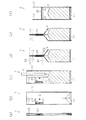
次に、包装袋1に対する充填物の充填方法を図6に基づいて説明する。
[開口工程]
まず、閉じた状態にある包装袋1(図6(a))の上辺部分を開口させ、両側面シート12を互いに離間させるとともに袋内にエアを吹き込み、袋全体を開いた状態とする(図6(b))。このとき、内蓋シート20は二つ折りの状態のまま、一方側の側面シート12に添うようにして屈曲する。そのため、内蓋シート20と他方側の側面シート12とが離間した状態となって、内蓋シート20の外面と他方側の側面シート12の内面との間に隙間Sが形成される。
(Function)
Next, the filling method of the filling material with respect to the
[Opening process]
First, the upper side portion of the
[充填工程]
包装袋1の開口部分を通じて、内蓋シート20と他方側の側面シート12との間に形成された隙間Sに充填ノズル31を挿入する(図6(c))。このとき、充填ノズル31の先端が内蓋シート20よりも下方に位置するように充填ノズル31を挿入する。そして、充填ノズル31から充填物Aを包装袋1内へ充填し、充填後、包装袋1内から充填ノズル31を退避させる。
[Filling process]
The filling nozzle 31 is inserted into the gap S formed between the
[接着工程]
両側面シート12上部の内面同士を密着させるようにして包装袋1を閉じた状態とする(図6(d))。このとき、内蓋シート20と他方側の側面シート12との間の隙間Sは無くなり、内蓋シート20と他方側の側面シート12とが密着した状態となる。また、内蓋シート20は一方側の側面シート12に対しても密着した状態となる。
[Adhesion process]
The
そして、内蓋シート20と両側面シート12とを密着させた状態で、内蓋シート20の外面下部と両側面シート12の内面とを、内蓋シート20の長側縁20bに沿って直線状に一定幅で熱溶着する。このとき、二つ折りにした内蓋シート20の内面には、長側縁20bに沿って非熱溶着部23が形成されているため、内蓋シート20の内面同士が熱溶着されることはない。したがって、内蓋シート20の長さ寸法L1から端部接着部22の突出長L2を引いた展開寸法L3の範囲で、二つ折りされた内蓋シート20の長側縁20b同士は互いに離間可能である(図2参照)。
Then, in a state where the
さらに、接着工程では、包装袋1の袋本体10の上辺部分を上辺に沿って熱溶着して包装袋1を密封する。接着工程における内蓋シート20の外面と両側面シート12との熱溶着、及び袋本体10の上辺部分の熱溶着は、包装袋1に対して外面側から加熱部材32を押し当てることにより行われる。この接着工程において、内蓋シート20と両側面シート12とが熱溶着されることによって、袋本体10に対して内蓋シート20が完全に接着された状態となる(図6(e))。以下では、袋本体10に対して内蓋シート20が完全に接着された包装袋1を内蓋付き包装袋2と記載する。
Further, in the bonding step, the upper side portion of the
次に、内蓋付き包装袋2から充填物Aを取り出す方法について説明する。
内蓋付き包装袋2から充填物Aを取り出す場合には、まず、切取溝16を起点として包装袋1の上部を切り取ることにより内蓋付き包装袋2を開封する。図6(e)における破線は、このときの切り取り線を示している。そして、上部が切り取られた内蓋付き包装袋2の開口を開く(図6(f))。その際、内蓋付き包装袋2の開口を開く動作に伴って、内蓋シート20は二つ折りの状態から、長側縁20b同士を互いに離間させるようにして袋内を上下に区画する平面状に展開される。参考として、図5には内蓋シート20を展開させた状態の内蓋付き包装袋2の斜視図を示している。そして、内蓋シート20を展開させた状態にて、開口側を下側に向けることにより、内蓋シート20の取出孔21を介して袋内の充填物Aを少量ずつ取り出すことができる。
Next, a method for taking out the filling A from the
When taking out the filling A from the
次に、本実施形態における効果について、以下に記載する。
(1)本実施形態の包装袋1は、シート材により上辺部分を開口可能な袋状に形成された袋本体10と、複数の取出孔21を有するシート材からなり、袋本体10内に取り付けられる内蓋シート20とを備えている。袋本体10の左辺及び右辺には、同袋本体10の側面を形成する一対の側面シート12同士を熱溶着してなる左辺接着領域13及び右辺接着領域14が設けられている。内蓋シート20は、上下二つ折りにされた状態で袋本体10内に配置されるとともに、その折辺方向の両端に設けられる端部接着部22が、袋本体10の左辺接着領域13及び右辺接着領域14にて一対の側面シート12と共に熱溶着されている。そして内蓋シート20の外面を側面シート12に対して未接着としている。
Next, the effect in this embodiment will be described below.
(1) The
これにより、充填物Aを充填する際に、内蓋シート20の取出孔21に関与させることなく充填ノズル31を内蓋シート20の外面と側面シート12の内面との間に挿入することが可能となる。そのため、袋本体10内において、内蓋シート20の下部に位置する収容部内へ充填ノズル31から充填物Aを直接充填することが可能となり、充填作業を素早く行うことができる。
Thereby, when filling the filling A, the filling nozzle 31 can be inserted between the outer surface of the
また、充填物Aの充填後において、互いに離間可能となるように未接着とされていた内蓋シート20と側面シート12とが接着される(接着工程)ことにより、内蓋シート20は充填物Aの取出量を規制するための内蓋として機能するようになる。このとき、内蓋シート20の端部接着部22が袋本体10に熱溶着されて、既に内蓋シート20は袋本体10内の所定位置に位置決めされた状態にある。そのため、内蓋シート20の外面と側面シート12との接着を容易に行うことができる。
In addition, after the filling A is filled, the
(2)本実施形態では、内蓋シート20の短側縁20aの両端部分に端部接着部22を設けている。これにより、接着工程後において、内蓋シート20をより確実に展開させることができる。つまり、内蓋シート20の短側縁20aの全体にわたって端部接着部22を設けると、内蓋シート20の短側縁20a全体が左辺接着領域13及び右辺接着領域14にて袋本体10に固定されることになる。この場合、左辺接着領域13及び右辺接着領域14に固定された内蓋シート20の短側縁20a部分に引っ張られて内蓋シート20を十分に展開させることが難しくなるが、上記構成によれば、そうした問題を回避することができる。
(2) In this embodiment, the edge
(3)二つ折りにした内蓋シート20の折辺24を上側にして、袋本体10内に内蓋シート20を取り付けている。上記構成によれば、内蓋シート20の折辺24を下側にして内蓋シート20を取り付けた場合と比較して、包装袋1内に充填ノズル31を挿入する際にノズル先端と内蓋シート20との間に引っ掛かりが生じ難くなる。したがって、包装袋1内に充填ノズル31をよりスムーズに挿入することができる。
(3) The
(4)充填工程において、充填ノズル31の先端が内蓋シート20よりも下方に位置するように充填ノズル31を挿入している。これにより、充填時において、内蓋シート20に充填物Aが付着することを抑制できる。内蓋シート20に対する充填物Aの付着を抑制することによって、続く接着工程における内蓋シート20と側面シート12との接着をより確実に行うことができるようになる。
(4) In the filling step, the filling nozzle 31 is inserted so that the tip of the filling nozzle 31 is positioned below the
なお、本実施形態は、次のように変更して具体化することも可能である。また、次の変更例を互いに組み合わせ、その組み合わせの構成のように上記実施形態を変更することも可能である。 In addition, this embodiment can also be changed and embodied as follows. Moreover, it is also possible to change the said embodiment like the structure of the combination of the following modification example mutually.
・ 本実施形態では、底面シート11及び一対の側面シート12から袋本体10を形成していたが、袋本体10を形成するシート材の構成はこれに限定されるものではない。たとえば、底面シート11を省略し、一対の側面シート12の下辺部分同士を熱溶着するようにしてもよい。また、一枚のシート材を左右に二つ折り又は三つ折りにすることによって、対向する一対の側面シート12を構成してもよい。
-In this embodiment, although the bag
・ 内蓋シート20の形状を適宜変更してもよい。たとえば、端部接着部22の突出長L2を左辺接着領域13及び右辺接着領域14の幅よりも大きく設定し(短側縁20a側の凹みを大きくする)、端部接着部22の先端側の一部のみが左辺接着領域13及び右辺接着領域14内に位置するように構成してもよい。
-The shape of the
また、本実施形態では、横長長方形状に形成される内蓋シート20の短側縁20aにおける両端部分に端部接着部22を設けていたが、短側縁20a全体にわたって端部接着部22を設けてもよい。この場合、包装袋1の製造時において、内蓋シート20を形成する第2シートに切欠25を設ける必要はない。なお、端部接着部22が短側縁20a全体にわたって形成されていれば、内蓋シート20の短側縁20a全体が一対の側面シート12に対して位置決め固定される。したがって、包装袋1の開口及び閉口が繰り返されたとしても、その短側縁20a部分における内蓋シート20の二つ折り状態が安定する。さらに、図7に示すように、内蓋シート20の全体形状を楕円状に形成し、これを二つ折りして配設するようにしてもよい。
Moreover, in this embodiment, although the edge
・ 内蓋シート20に貫通形成される取出孔21の大きさ及び形状は特に限定されるものではない。また、内蓋シート20における取出孔21の形成位置も特に限定されるものではない。
-The magnitude | size and shape of the
・ 内蓋シート20の第1面における非熱溶着部23の形成位置は本実施形態の構成に限定されるものではない。少なくとも、内蓋シート20を二つ折りにした状態で、左辺接着領域13及び右辺接着領域14に配置されることとなる端部接着部22の内面同士が熱溶着可能であり、且つ接着工程時に内蓋シート20の内面同士(特に内面中央部同士)が熱溶着されないように構成されていればよい。たとえば、内蓋シート20の第1面における端部接着部22以外の部位すべてを非熱溶着部23とする構成であってもよい。
-The formation position of the
・ 内蓋シート20の第1面の一部に非熱溶着部23を設ける代わりに、内蓋シート20の第1面、及びその反対側の面である第2面に対して、それぞれ溶解温度の異なる熱溶着層を形成する構成としてもよい。具体的には、二つ折りした状態で外面となる第2面には、低温溶解性の熱溶着層を形成するとともに、二つ折りした状態で内面となる第1面には、第2面に形成する熱溶着層よりも溶解温度の高い高温溶解性の熱溶着層を形成する。
-Instead of providing the
そして、包装袋1の左辺接着領域13及び右辺接着領域14を形成する際(幅方向溶着部を形成する際)には、上記高温溶解性の熱溶着層が溶解可能な温度で熱溶着を行う。一方、接着工程時には、上記低温溶解性の熱溶着層が溶解可能、且つ上記高温溶解性の熱溶着層が溶解不可能な温度で熱溶着を行う。これにより、左辺接着領域13及び右辺接着領域14を形成する際、左辺接着領域13及び右辺接着領域14内において内蓋シート20の端部接着部22の内面同士を確実に熱溶着することができる。そして、内蓋シート20の外面(第2面)と側面シート12の内面とを熱溶着する接着工程時に、内蓋シート20の内面同士(第1面同士)が熱溶着されてしまうことを回避することができる。
And when forming the left side adhesion | attachment area |
なお、上記低温溶解性の熱溶着層と上記高温溶解性の熱溶着層の組み合わせとしては、例えば、溶解温度が約80℃である直鎖状低密度ポリエチレン(LLDPE)と、溶解温度が約160℃である無延伸ポリプロピレン(CPP)との組み合わせが挙げられる。また、側面シート12に形成する熱融着層は、上記低温溶解性の熱溶着層及び上記高温溶解性の熱溶着層のいずれであってもよいが、接着工程時における熱溶着性の観点から、内蓋シート20の第2面と同様の上記低温溶解性の熱溶着層とすることが好ましい。
Examples of the combination of the low-temperature soluble heat-welded layer and the high-temperature soluble heat-welded layer include, for example, linear low density polyethylene (LLDPE) having a melting temperature of about 80 ° C. and a melting temperature of about 160. A combination with unstretched polypropylene (CPP) that is at 0 ° C. is mentioned. Further, the heat-sealing layer formed on the
さらに、内蓋シート20の第1面全体に上記高温溶解性の熱溶着層を形成するのではなく、同第1面の一部に上記高温溶解性の熱溶着層を形成する構成としてもよい。たとえば、上記実施形態における内蓋シート20の第1面における非熱溶着部23を形成していた部位に上記高温溶解性の熱溶着層を形成し、その他の部位には上記低温溶解性の熱溶着層を形成する構成としてもよい。また、第1面における端部接着部22に対応する部位に上記低温溶解性の熱溶着層を形成し、その他の部位には上記高温溶解性の熱溶着層を形成する構成としてもよい。
Furthermore, it is good also as a structure which does not form the said high temperature soluble heat welding layer in the whole 1st surface of the
・ 包装袋1の製造時に用いる第2シートについて、隣接する非熱溶着部23間の間隔を、袋本体10における左辺接着領域13の幅と右辺接着領域14の幅の合計に相当する大きさよりも大きくしてもよい。この場合、隣接する非熱溶着部23間の間隔は、包装袋1の製造時に形成される幅方向溶着部の幅よりも大きくなり、非熱溶着部23の幅は、左辺接着領域13と右辺接着領域14との間の間隔(上記実施形態の展開寸法L3)よりも小さくなる。そのため、仮に包装袋1の製造時に幅方向溶着部の形成位置が各シートの長さ方向に多少ずれたとしても、幅方向溶着部が第2シートに形成される非熱溶着部23に重なることが抑制される。なお、幅方向溶着部が非熱溶着部23に重なってしまうと、幅方向溶着部内にて第2シートの内面同士を熱溶着させることができず、包装袋1となったときに左辺接着領域13及び右辺接着領域14内に隙間が形成されてしまうおそれがある。
-About the 2nd sheet | seat used at the time of manufacture of the
・ 二つ折りにした内蓋シート20の折辺24を下側にして内蓋シート20を袋本体10内に取り付けてもよい。また、二つ折りにした内蓋シート20の一方側の端部接着部22が袋本体10の左辺接着領域13内に位置し、他方側の端部接着部22が右辺接着領域14内に位置しているのであれば、袋本体10に対して内蓋シート20を斜めに取り付けてもよい。つまり、二つ折りにした内蓋シート20の一方側の端部接着部22と他方側の端部接着部22の上下方向における位置が異なっていてもよい。
The
・ 本実施形態では、二つ折りにされた内蓋シート20の両外面を、袋本体10の側面シート12に対して共に未接着としていたが、内蓋シート20の一方側の外面のみを側面シート12に対して未接着とし、他方側の外面については側面シート12に熱溶着するように構成してもよい。この場合、開口工程における内蓋シート20の屈曲方向が一方向に規定される。
In the present embodiment, both outer surfaces of the folded
・ 一般的に、包装袋に用いられるような樹脂シートは剛性が小さいために、曲がった状態で維持することが難しい。そのため、包装袋1を開口させた際にも、側面シート12を円弧状に曲げた状態を維持することが難しく、元の閉口した状態に戻りやすい。
-Generally, a resin sheet used for a packaging bag has a low rigidity, and is difficult to maintain in a bent state. Therefore, even when the
そこで、図8に示すように、袋本体10の上辺近傍、具体的には、側面シート12における内蓋シート20の端部接着部22との接着部分より上部に、袋本体10の上辺に沿って延びる補強部材17を取り付けることが好ましい。補強部材17によって袋本体10の上辺近傍に剛性が付与されることで、袋本体10の開口時に側面シート12の屈曲状態が維持されやすくなり、閉口した状態に戻ることが抑制される。そして、袋本体10の開口状態が維持されやすくなることによって、充填工程における充填物Aの充填作業をより容易に行うことができるようになる。また、内蓋シート20の外面を接着した後の内蓋付き包装袋2となった後は、内蓋付き包装袋2の開口状態が維持され易くなるため、充填物Aをより確実に袋外に取り出すことができるようになる。
Therefore, as shown in FIG. 8, near the upper side of the
なお、補強部材17としては、側面シート12よりも剛性が大きく、且つ可撓性を有する部材、例えば、金属又は樹脂からなる線状部材や帯状部材、金属又は樹脂からなる線状部材を帯状の樹脂フィルムに取り付けた部材(所謂、ツイストタイ等)を用いることができる。
In addition, as the reinforcing
・ 図9(a)及び(b)に示すように、雄型テープと雌型テープとからなるファスナ部材33を備える包装袋1としてもよい。この場合、ファスナ部材33は雄型テープと雌型テープとを噛合させた状態で袋本体10内に配置されるが、ファスナ部材33も内蓋シート20と同様にして袋本体10に熱溶着する。つまり、ファスナ部材33の両端部を、袋本体10の左辺接着領域13及び右辺接着領域14内にて、側面シート12と共に一体に熱溶着する。そして、ファスナ部材33の少なくとも一方の外面は、袋本体10の側面シート12に対して未接着の状態とし、ファスナ部材33の外面と側面シート12との間を離間可能に構成する。
-As shown to Fig.9 (a) and (b), it is good also as the
また、ファスナ部材33の両外面を共に袋本体10の側面シート12に対して接着させた構成としてもよい。この場合には、開口工程において、噛合状態にあるファスナ部材33の雄型テープと雌型テープとを強制的に離間させて包装袋1を開口させるようにすればよい。
Further, both the outer surfaces of the
・ 本実施形態では、接着工程において、内蓋シート20の外面下部と両側面シート12の内面とを、内蓋シート20の長側縁20bに沿った一定幅の直線状に熱溶着していたが、この熱溶着部位の形状を変更してもよい。
In the present embodiment, in the bonding step, the lower outer surface of the
たとえば、内蓋シート20が図7に示すような楕円状である場合には、内蓋シート20の円弧状の側縁に沿って上側に凹む一定幅の曲線状に熱溶着部位を形成することが好ましい。本実施形態のように、上記熱溶着部位を内蓋シート20の長側縁20bに沿った直線状に形成すると、内蓋シート20の展開時に、図5に示すように内蓋シート20の両端部分に余りが生じて浮き上り部分20cが形成されてしまう。しかし、上側に凹む一定幅の曲線状に熱溶着部位を形成した場合には、上記浮き上り部分20cの形成を抑制することができる。
For example, when the
なお、内蓋シート20が図3に示すような横長長方形状であったとしても、上記熱溶着部位を上側に凹む一定幅の曲線状に形成する、或いは上側に凹む一定幅の曲線と内蓋シート20の短側縁20a及び長側縁20bとによって囲まれた部位を上記熱溶着部位とすることにより、上記浮き上り部分20cの形成を抑制することが可能である。
In addition, even if the
・ 包装袋1を構成する各シート同士の接着方法は熱融着に限定されるものではなく、包装袋を形成する場合に一般的に採用される接着方法(例えば、接着剤を用いた接着方法等)のいずれを採用してもよい。なお、本実施形態では、各シートとして熱溶着層を有する樹脂シートを用いていたが、熱融着以外の接着方法を採用する場合には、必ずしも熱溶着性層を必要としない。
-The bonding method between the sheets constituting the
・ 包装袋1に充填する充填物Aは特に限定されるものではない。たとえば、粉チーズ、食塩、小麦粉等の粉粒体、清涼飲料水、洗剤等の液体、ゼリー飲料等のゲル状物質、及び味噌等のペースト状物質を充填物Aとすることができる。
-The filling A filled in the
・ 次のような方法でも本願課題を解決することが可能である。つまり、袋本体10に関し、二つ折りにした底面シート11の一方側の外面と同外面と対向する側面シート12の内面とを未接着とし、底面シート11の外面と側面シート12との間を離間可能に構成する。内蓋シート20については、図5に示すように袋本体10に完全に接着させた状態とする。
-The following problem can be solved by the following method. That is, with respect to the
この包装袋を逆さの状態とし、底面シート11の外面と側面シート12との間に充填ノズル31を挿入して、袋内に充填物Aを充填する。充填後、底面シート11の外面と側面シート12を接着して袋本体10の底部分を封止する。この場合にも、上記(1)と類似の効果を得ることができる。なお、充填物Aを充填する際には、二つ折り状態の内蓋シート20を挟むようにして包装袋の上部をクランプし、内蓋シート20が展開しないように保持しておくことが好ましい。このようにすれば、充填時に、内蓋シート20の取出孔21から充填物Aがこぼれることを防止することができる。
The packaging bag is turned upside down, and the filling nozzle 31 is inserted between the outer surface of the
次に、上記実施形態及び別例から把握できる技術的思想について記載する。
(イ)内部に充填物を充填した後、前記内蓋シートの外面と前記側面シートとを接着して使用されることを特徴とする包装袋。
Next, a technical idea that can be grasped from the above embodiment and another example will be described.
(B) A packaging bag characterized by being used by adhering the outer surface of the inner lid sheet and the side sheet after filling the inside with a filler.
(ロ)雄型テープと雌型テープとからなるファスナ部材を備え、該ファスナ部材は、雄型テープと雌型テープとを噛合させた状態で前記一対の側面シート間に挟み込まれており、前記ファスナ部材の両端部が、前記袋本体の左辺接着領域及び右辺接着領域にて前記一対の側面シートと共に接着されており、前記ファスナ部材の少なくとも一方の外面を前記側面シートに対して未接着とすることにより、前記ファスナ部材の外面と前記側面シートとの間を離間可能に構成したことを特徴とする包装袋。 (B) a fastener member composed of a male tape and a female tape, the fastener member being sandwiched between the pair of side sheets in a state where the male tape and the female tape are engaged, Both ends of the fastener member are bonded together with the pair of side sheets in the left side bonding region and the right side bonding region of the bag body, and at least one outer surface of the fastener member is not bonded to the side sheet. Thus, the packaging bag is configured so that the outer surface of the fastener member and the side sheet can be separated from each other.
(ハ)前記袋本体の上辺部分を開口させるとともに、前記内蓋シートの前記側縁部と前記側面シートとの間を離間させる開口工程と、前記内蓋シートの外面と前記側面シートと間の隙間を通じて、前記包装袋内に充填物を充填する充填工程と、前記内蓋シートの外面と前記側面シートとを接着する接着工程とを有することを特徴とする充填物入り包装袋の製造方法。 (C) an opening step of opening the upper side portion of the bag body and separating the side edge portion of the inner lid sheet from the side sheet; and between the outer surface of the inner lid sheet and the side sheet. A method for producing a filled-in packaging bag, comprising: a filling step for filling the packing bag with a filling through a gap; and an adhesion step for bonding the outer surface of the inner lid sheet and the side sheet.
A…充填物、S…隙間、1…包装袋、10…袋本体、11…底面シート、12…側面シート、13…左辺接着領域、14…右辺接着領域、15…下辺接着領域、17…補強部材、20…内蓋シート、21…取出孔、22…端部接着部、24…折辺。 DESCRIPTION OF SYMBOLS A ... Filling thing, S ... Gap, 1 ... Packaging bag, 10 ... Bag main body, 11 ... Bottom sheet, 12 ... Side sheet, 13 ... Left side adhesion area, 14 ... Right side adhesion area, 15 ... Lower side adhesion area, 17 ... Reinforcement Member, 20 ... inner lid sheet, 21 ... take-out hole, 22 ... end bonded portion, 24 ... folded side.
Claims (3)
前記袋本体の左辺及び右辺には、同袋本体の側面を形成する一対の側面シート同士を接着してなる左辺接着領域及び右辺接着領域が設けられ、
前記内蓋シートは、上下二つ折りにされた状態で前記袋本体内に配置されるとともに、その折辺方向の両端に設けられる端部接着部が、前記袋本体の左辺接着領域及び右辺接着領域にて前記一対の側面シートと共に接着されており、
二つ折りにされた前記内蓋シートにおける少なくとも一方側の外面を前記側面シートに対して未接着とすることにより、前記内蓋シートの外面と前記側面シートとの間を離間可能に構成したことを特徴とする包装袋。 A bag body formed in a bag shape capable of opening an upper side portion by a sheet material, and an inner lid sheet attached to the bag body and made of a sheet material having a plurality of extraction holes,
The left side and the right side of the bag body are provided with a left side bonding region and a right side bonding region formed by bonding a pair of side sheets forming the side surface of the bag body,
The inner lid sheet is arranged in the bag body in a state of being folded in the upper and lower sides, and the end bonding portions provided at both ends in the folding side direction are the left side bonding region and the right side bonding region of the bag main body. And bonded together with the pair of side sheets,
The outer cover of the inner lid sheet folded in half is not bonded to the side sheet so that the outer surface of the inner cover sheet and the side sheet can be separated from each other. Characteristic packaging bag.
前記袋本体の上辺部分を開口させるとともに、前記内蓋シートの外面と前記側面シートとを離間させる開口工程と、
前記内蓋シートの外面と前記側面シートと間の隙間を通じて、前記包装袋内に充填物を充填する充填工程と、
前記内蓋シートの外面と前記側面シートとを接着する接着工程とを有することを特徴とする充填方法。 A filling method for the packaging bag according to claim 1 or 2,
An opening step of opening the upper side portion of the bag body and separating the outer surface of the inner lid sheet and the side sheet;
A filling step of filling the packaging bag with a filler through a gap between the outer surface of the inner lid sheet and the side sheet;
A filling method comprising a bonding step of bonding the outer surface of the inner lid sheet and the side sheet.
Priority Applications (1)
| Application Number | Priority Date | Filing Date | Title |
|---|---|---|---|
| JP2011048154A JP5719642B2 (en) | 2011-03-04 | 2011-03-04 | Packaging bag and filling method for the packaging bag |
Applications Claiming Priority (1)
| Application Number | Priority Date | Filing Date | Title |
|---|---|---|---|
| JP2011048154A JP5719642B2 (en) | 2011-03-04 | 2011-03-04 | Packaging bag and filling method for the packaging bag |
Related Child Applications (1)
| Application Number | Title | Priority Date | Filing Date |
|---|---|---|---|
| JP2015055132A Division JP5824177B2 (en) | 2015-03-18 | 2015-03-18 | Packaging bag |
Publications (2)
| Publication Number | Publication Date |
|---|---|
| JP2012184021A true JP2012184021A (en) | 2012-09-27 |
| JP5719642B2 JP5719642B2 (en) | 2015-05-20 |
Family
ID=47014464
Family Applications (1)
| Application Number | Title | Priority Date | Filing Date |
|---|---|---|---|
| JP2011048154A Active JP5719642B2 (en) | 2011-03-04 | 2011-03-04 | Packaging bag and filling method for the packaging bag |
Country Status (1)
| Country | Link |
|---|---|
| JP (1) | JP5719642B2 (en) |
Cited By (5)
| Publication number | Priority date | Publication date | Assignee | Title |
|---|---|---|---|---|
| JP2014162519A (en) * | 2013-02-26 | 2014-09-08 | Oshio Sangyo Kk | Packaging bag and filling method for packaging bag |
| NO20141330A1 (en) * | 2014-11-07 | 2016-05-09 | Fimtech As | A dosing device |
| JP2019182498A (en) * | 2018-04-12 | 2019-10-24 | 凸版印刷株式会社 | Packaging bag |
| JP2020006997A (en) * | 2018-07-06 | 2020-01-16 | 凸版印刷株式会社 | Standing pouch |
| WO2022258579A3 (en) * | 2021-06-08 | 2023-02-02 | Hdg-Verpackungsmaschinen Gmbh | Method for manufacturing a packing container having an inlay, insertion device, and packaging machine |
Citations (7)
| Publication number | Priority date | Publication date | Assignee | Title |
|---|---|---|---|---|
| JPH0958706A (en) * | 1995-08-11 | 1997-03-04 | Kao Corp | Self-supporting packing bag and production thereof |
| US5709479A (en) * | 1996-09-06 | 1998-01-20 | Kapak Corp. | Bag construction for distributing material |
| JPH1081347A (en) * | 1996-09-09 | 1998-03-31 | Sanwa Kogyo Kk | Bag with dispensing function |
| US6375037B1 (en) * | 2000-10-10 | 2002-04-23 | Kapak Corporation | Bag construction for distributing material |
| JP2004203414A (en) * | 2002-12-25 | 2004-07-22 | Fujimori Kogyo Co Ltd | Packaging bag and method for measuring stored stuff |
| JP2004256120A (en) * | 2003-02-24 | 2004-09-16 | Fuji Seal Inc | Pouch container |
| JP2006193173A (en) * | 2005-01-12 | 2006-07-27 | Hosokawa Yoko Co Ltd | Packaging bag and manufacturing method therefor |
-
2011
- 2011-03-04 JP JP2011048154A patent/JP5719642B2/en active Active
Patent Citations (7)
| Publication number | Priority date | Publication date | Assignee | Title |
|---|---|---|---|---|
| JPH0958706A (en) * | 1995-08-11 | 1997-03-04 | Kao Corp | Self-supporting packing bag and production thereof |
| US5709479A (en) * | 1996-09-06 | 1998-01-20 | Kapak Corp. | Bag construction for distributing material |
| JPH1081347A (en) * | 1996-09-09 | 1998-03-31 | Sanwa Kogyo Kk | Bag with dispensing function |
| US6375037B1 (en) * | 2000-10-10 | 2002-04-23 | Kapak Corporation | Bag construction for distributing material |
| JP2004203414A (en) * | 2002-12-25 | 2004-07-22 | Fujimori Kogyo Co Ltd | Packaging bag and method for measuring stored stuff |
| JP2004256120A (en) * | 2003-02-24 | 2004-09-16 | Fuji Seal Inc | Pouch container |
| JP2006193173A (en) * | 2005-01-12 | 2006-07-27 | Hosokawa Yoko Co Ltd | Packaging bag and manufacturing method therefor |
Cited By (7)
| Publication number | Priority date | Publication date | Assignee | Title |
|---|---|---|---|---|
| JP2014162519A (en) * | 2013-02-26 | 2014-09-08 | Oshio Sangyo Kk | Packaging bag and filling method for packaging bag |
| NO20141330A1 (en) * | 2014-11-07 | 2016-05-09 | Fimtech As | A dosing device |
| US10773874B2 (en) | 2014-11-07 | 2020-09-15 | Fimtech As | Dosage device |
| JP2019182498A (en) * | 2018-04-12 | 2019-10-24 | 凸版印刷株式会社 | Packaging bag |
| JP7131043B2 (en) | 2018-04-12 | 2022-09-06 | 凸版印刷株式会社 | packaging bag |
| JP2020006997A (en) * | 2018-07-06 | 2020-01-16 | 凸版印刷株式会社 | Standing pouch |
| WO2022258579A3 (en) * | 2021-06-08 | 2023-02-02 | Hdg-Verpackungsmaschinen Gmbh | Method for manufacturing a packing container having an inlay, insertion device, and packaging machine |
Also Published As
| Publication number | Publication date |
|---|---|
| JP5719642B2 (en) | 2015-05-20 |
Similar Documents
| Publication | Publication Date | Title |
|---|---|---|
| JP5221515B2 (en) | Slider-operated bag with reclosable spout | |
| EP2384992B1 (en) | Side-gusseted bag and method for manufacturing the same | |
| JP5690694B2 (en) | Composite container | |
| JP5719642B2 (en) | Packaging bag and filling method for the packaging bag | |
| JP6516027B2 (en) | Refill container | |
| JP2011131897A (en) | Standing pouch and method of manufacturing the same | |
| JP6394166B2 (en) | Liquid packaging container | |
| JP4629414B2 (en) | A pouch with a spout part in which the pour-out auxiliary member and the pour-out auxiliary member are attached to the spout part of the bag | |
| JP6977423B2 (en) | Packaging bag with spout | |
| JP5899557B2 (en) | Pouch container | |
| JP7110555B2 (en) | Packaging bag with spout nozzle | |
| JP5824177B2 (en) | Packaging bag | |
| JP3135179U (en) | Stick-shaped packaging bag | |
| JP6288856B2 (en) | Composite container, package and composite container manufacturing method | |
| JP5463560B2 (en) | Refillable pouch | |
| JP2009001311A (en) | Gusset bag | |
| JP6672650B2 (en) | Manufacturing method of self-standing packaging bag with spout | |
| JP4313659B2 (en) | Packaging bag and manufacturing method thereof | |
| JP6406609B2 (en) | Packaging bag | |
| JP7069704B2 (en) | Pouch | |
| JP2011063320A (en) | Composite container | |
| JP5690483B2 (en) | Resealable packaging bag | |
| JP2011063325A (en) | Composite container | |
| JP2011063326A (en) | Composite container | |
| JP7028571B2 (en) | Gazette bag |
Legal Events
| Date | Code | Title | Description |
|---|---|---|---|
| A621 | Written request for application examination |
Free format text: JAPANESE INTERMEDIATE CODE: A621 Effective date: 20140122 |
|
| A977 | Report on retrieval |
Free format text: JAPANESE INTERMEDIATE CODE: A971007 Effective date: 20140929 |
|
| A131 | Notification of reasons for refusal |
Free format text: JAPANESE INTERMEDIATE CODE: A131 Effective date: 20141007 |
|
| A521 | Request for written amendment filed |
Free format text: JAPANESE INTERMEDIATE CODE: A523 Effective date: 20141208 |
|
| TRDD | Decision of grant or rejection written | ||
| A01 | Written decision to grant a patent or to grant a registration (utility model) |
Free format text: JAPANESE INTERMEDIATE CODE: A01 Effective date: 20150303 |
|
| A61 | First payment of annual fees (during grant procedure) |
Free format text: JAPANESE INTERMEDIATE CODE: A61 Effective date: 20150323 |
|
| R150 | Certificate of patent or registration of utility model |
Ref document number: 5719642 Country of ref document: JP Free format text: JAPANESE INTERMEDIATE CODE: R150 |
|
| R250 | Receipt of annual fees |
Free format text: JAPANESE INTERMEDIATE CODE: R250 |
|
| R250 | Receipt of annual fees |
Free format text: JAPANESE INTERMEDIATE CODE: R250 |
|
| R250 | Receipt of annual fees |
Free format text: JAPANESE INTERMEDIATE CODE: R250 |