JP2012183322A - Improvement of substance delivery device - Google Patents
Improvement of substance delivery device Download PDFInfo
- Publication number
- JP2012183322A JP2012183322A JP2012103680A JP2012103680A JP2012183322A JP 2012183322 A JP2012183322 A JP 2012183322A JP 2012103680 A JP2012103680 A JP 2012103680A JP 2012103680 A JP2012103680 A JP 2012103680A JP 2012183322 A JP2012183322 A JP 2012183322A
- Authority
- JP
- Japan
- Prior art keywords
- container
- delivery device
- plunger
- substance delivery
- substance
- Prior art date
- Legal status (The legal status is an assumption and is not a legal conclusion. Google has not performed a legal analysis and makes no representation as to the accuracy of the status listed.)
- Granted
Links
Images


Classifications
-
- A—HUMAN NECESSITIES
- A61—MEDICAL OR VETERINARY SCIENCE; HYGIENE
- A61M—DEVICES FOR INTRODUCING MEDIA INTO, OR ONTO, THE BODY; DEVICES FOR TRANSDUCING BODY MEDIA OR FOR TAKING MEDIA FROM THE BODY; DEVICES FOR PRODUCING OR ENDING SLEEP OR STUPOR
- A61M5/00—Devices for bringing media into the body in a subcutaneous, intra-vascular or intramuscular way; Accessories therefor, e.g. filling or cleaning devices, arm-rests
- A61M5/178—Syringes
- A61M5/20—Automatic syringes, e.g. with automatically actuated piston rod, with automatic needle injection, filling automatically
- A61M5/2033—Spring-loaded one-shot injectors with or without automatic needle insertion
-
- A—HUMAN NECESSITIES
- A61—MEDICAL OR VETERINARY SCIENCE; HYGIENE
- A61M—DEVICES FOR INTRODUCING MEDIA INTO, OR ONTO, THE BODY; DEVICES FOR TRANSDUCING BODY MEDIA OR FOR TAKING MEDIA FROM THE BODY; DEVICES FOR PRODUCING OR ENDING SLEEP OR STUPOR
- A61M5/00—Devices for bringing media into the body in a subcutaneous, intra-vascular or intramuscular way; Accessories therefor, e.g. filling or cleaning devices, arm-rests
- A61M5/178—Syringes
- A61M5/31—Details
- A61M5/315—Pistons; Piston-rods; Guiding, blocking or restricting the movement of the rod or piston; Appliances on the rod for facilitating dosing ; Dosing mechanisms
- A61M5/31501—Means for blocking or restricting the movement of the rod or piston
-
- A—HUMAN NECESSITIES
- A61—MEDICAL OR VETERINARY SCIENCE; HYGIENE
- A61M—DEVICES FOR INTRODUCING MEDIA INTO, OR ONTO, THE BODY; DEVICES FOR TRANSDUCING BODY MEDIA OR FOR TAKING MEDIA FROM THE BODY; DEVICES FOR PRODUCING OR ENDING SLEEP OR STUPOR
- A61M5/00—Devices for bringing media into the body in a subcutaneous, intra-vascular or intramuscular way; Accessories therefor, e.g. filling or cleaning devices, arm-rests
- A61M5/178—Syringes
- A61M5/31—Details
- A61M5/315—Pistons; Piston-rods; Guiding, blocking or restricting the movement of the rod or piston; Appliances on the rod for facilitating dosing ; Dosing mechanisms
- A61M5/31525—Dosing
- A61M5/31528—Dosing by means of rotational movements, e.g. screw-thread mechanisms
-
- A—HUMAN NECESSITIES
- A61—MEDICAL OR VETERINARY SCIENCE; HYGIENE
- A61M—DEVICES FOR INTRODUCING MEDIA INTO, OR ONTO, THE BODY; DEVICES FOR TRANSDUCING BODY MEDIA OR FOR TAKING MEDIA FROM THE BODY; DEVICES FOR PRODUCING OR ENDING SLEEP OR STUPOR
- A61M5/00—Devices for bringing media into the body in a subcutaneous, intra-vascular or intramuscular way; Accessories therefor, e.g. filling or cleaning devices, arm-rests
- A61M5/178—Syringes
- A61M5/31—Details
- A61M5/32—Needles; Details of needles pertaining to their connection with syringe or hub; Accessories for bringing the needle into, or holding the needle on, the body; Devices for protection of needles
- A61M5/3202—Devices for protection of the needle before use, e.g. caps
-
- A—HUMAN NECESSITIES
- A61—MEDICAL OR VETERINARY SCIENCE; HYGIENE
- A61M—DEVICES FOR INTRODUCING MEDIA INTO, OR ONTO, THE BODY; DEVICES FOR TRANSDUCING BODY MEDIA OR FOR TAKING MEDIA FROM THE BODY; DEVICES FOR PRODUCING OR ENDING SLEEP OR STUPOR
- A61M5/00—Devices for bringing media into the body in a subcutaneous, intra-vascular or intramuscular way; Accessories therefor, e.g. filling or cleaning devices, arm-rests
- A61M5/178—Syringes
- A61M5/31—Details
- A61M5/32—Needles; Details of needles pertaining to their connection with syringe or hub; Accessories for bringing the needle into, or holding the needle on, the body; Devices for protection of needles
- A61M5/3205—Apparatus for removing or disposing of used needles or syringes, e.g. containers; Means for protection against accidental injuries from used needles
- A61M5/321—Means for protection against accidental injuries by used needles
- A61M5/3243—Means for protection against accidental injuries by used needles being axially-extensible, e.g. protective sleeves coaxially slidable on the syringe barrel
- A61M5/326—Fully automatic sleeve extension, i.e. in which triggering of the sleeve does not require a deliberate action by the user
-
- A—HUMAN NECESSITIES
- A61—MEDICAL OR VETERINARY SCIENCE; HYGIENE
- A61M—DEVICES FOR INTRODUCING MEDIA INTO, OR ONTO, THE BODY; DEVICES FOR TRANSDUCING BODY MEDIA OR FOR TAKING MEDIA FROM THE BODY; DEVICES FOR PRODUCING OR ENDING SLEEP OR STUPOR
- A61M5/00—Devices for bringing media into the body in a subcutaneous, intra-vascular or intramuscular way; Accessories therefor, e.g. filling or cleaning devices, arm-rests
- A61M5/178—Syringes
- A61M5/20—Automatic syringes, e.g. with automatically actuated piston rod, with automatic needle injection, filling automatically
- A61M2005/206—With automatic needle insertion
-
- A—HUMAN NECESSITIES
- A61—MEDICAL OR VETERINARY SCIENCE; HYGIENE
- A61M—DEVICES FOR INTRODUCING MEDIA INTO, OR ONTO, THE BODY; DEVICES FOR TRANSDUCING BODY MEDIA OR FOR TAKING MEDIA FROM THE BODY; DEVICES FOR PRODUCING OR ENDING SLEEP OR STUPOR
- A61M5/00—Devices for bringing media into the body in a subcutaneous, intra-vascular or intramuscular way; Accessories therefor, e.g. filling or cleaning devices, arm-rests
- A61M5/178—Syringes
- A61M5/20—Automatic syringes, e.g. with automatically actuated piston rod, with automatic needle injection, filling automatically
- A61M2005/2073—Automatic syringes, e.g. with automatically actuated piston rod, with automatic needle injection, filling automatically preventing premature release, e.g. by making use of a safety lock
-
- A—HUMAN NECESSITIES
- A61—MEDICAL OR VETERINARY SCIENCE; HYGIENE
- A61M—DEVICES FOR INTRODUCING MEDIA INTO, OR ONTO, THE BODY; DEVICES FOR TRANSDUCING BODY MEDIA OR FOR TAKING MEDIA FROM THE BODY; DEVICES FOR PRODUCING OR ENDING SLEEP OR STUPOR
- A61M5/00—Devices for bringing media into the body in a subcutaneous, intra-vascular or intramuscular way; Accessories therefor, e.g. filling or cleaning devices, arm-rests
- A61M5/178—Syringes
- A61M5/24—Ampoule syringes, i.e. syringes with needle for use in combination with replaceable ampoules or carpules, e.g. automatic
- A61M2005/2403—Ampoule inserted into the ampoule holder
- A61M2005/2407—Ampoule inserted into the ampoule holder from the rear
-
- A—HUMAN NECESSITIES
- A61—MEDICAL OR VETERINARY SCIENCE; HYGIENE
- A61M—DEVICES FOR INTRODUCING MEDIA INTO, OR ONTO, THE BODY; DEVICES FOR TRANSDUCING BODY MEDIA OR FOR TAKING MEDIA FROM THE BODY; DEVICES FOR PRODUCING OR ENDING SLEEP OR STUPOR
- A61M5/00—Devices for bringing media into the body in a subcutaneous, intra-vascular or intramuscular way; Accessories therefor, e.g. filling or cleaning devices, arm-rests
- A61M5/178—Syringes
- A61M5/31—Details
- A61M5/315—Pistons; Piston-rods; Guiding, blocking or restricting the movement of the rod or piston; Appliances on the rod for facilitating dosing ; Dosing mechanisms
- A61M5/31501—Means for blocking or restricting the movement of the rod or piston
- A61M2005/31508—Means for blocking or restricting the movement of the rod or piston provided on the piston-rod
-
- A—HUMAN NECESSITIES
- A61—MEDICAL OR VETERINARY SCIENCE; HYGIENE
- A61M—DEVICES FOR INTRODUCING MEDIA INTO, OR ONTO, THE BODY; DEVICES FOR TRANSDUCING BODY MEDIA OR FOR TAKING MEDIA FROM THE BODY; DEVICES FOR PRODUCING OR ENDING SLEEP OR STUPOR
- A61M5/00—Devices for bringing media into the body in a subcutaneous, intra-vascular or intramuscular way; Accessories therefor, e.g. filling or cleaning devices, arm-rests
- A61M5/178—Syringes
- A61M5/31—Details
- A61M5/32—Needles; Details of needles pertaining to their connection with syringe or hub; Accessories for bringing the needle into, or holding the needle on, the body; Devices for protection of needles
- A61M5/3205—Apparatus for removing or disposing of used needles or syringes, e.g. containers; Means for protection against accidental injuries from used needles
- A61M5/321—Means for protection against accidental injuries by used needles
- A61M5/3243—Means for protection against accidental injuries by used needles being axially-extensible, e.g. protective sleeves coaxially slidable on the syringe barrel
- A61M5/3245—Constructional features thereof, e.g. to improve manipulation or functioning
- A61M2005/3247—Means to impede repositioning of protection sleeve from needle covering to needle uncovering position
-
- A—HUMAN NECESSITIES
- A61—MEDICAL OR VETERINARY SCIENCE; HYGIENE
- A61M—DEVICES FOR INTRODUCING MEDIA INTO, OR ONTO, THE BODY; DEVICES FOR TRANSDUCING BODY MEDIA OR FOR TAKING MEDIA FROM THE BODY; DEVICES FOR PRODUCING OR ENDING SLEEP OR STUPOR
- A61M5/00—Devices for bringing media into the body in a subcutaneous, intra-vascular or intramuscular way; Accessories therefor, e.g. filling or cleaning devices, arm-rests
- A61M5/178—Syringes
- A61M5/24—Ampoule syringes, i.e. syringes with needle for use in combination with replaceable ampoules or carpules, e.g. automatic
-
- A—HUMAN NECESSITIES
- A61—MEDICAL OR VETERINARY SCIENCE; HYGIENE
- A61M—DEVICES FOR INTRODUCING MEDIA INTO, OR ONTO, THE BODY; DEVICES FOR TRANSDUCING BODY MEDIA OR FOR TAKING MEDIA FROM THE BODY; DEVICES FOR PRODUCING OR ENDING SLEEP OR STUPOR
- A61M5/00—Devices for bringing media into the body in a subcutaneous, intra-vascular or intramuscular way; Accessories therefor, e.g. filling or cleaning devices, arm-rests
- A61M5/178—Syringes
- A61M5/31—Details
- A61M5/3146—Priming, e.g. purging, reducing backlash or clearance
-
- A—HUMAN NECESSITIES
- A61—MEDICAL OR VETERINARY SCIENCE; HYGIENE
- A61M—DEVICES FOR INTRODUCING MEDIA INTO, OR ONTO, THE BODY; DEVICES FOR TRANSDUCING BODY MEDIA OR FOR TAKING MEDIA FROM THE BODY; DEVICES FOR PRODUCING OR ENDING SLEEP OR STUPOR
- A61M5/00—Devices for bringing media into the body in a subcutaneous, intra-vascular or intramuscular way; Accessories therefor, e.g. filling or cleaning devices, arm-rests
- A61M5/178—Syringes
- A61M5/31—Details
- A61M5/315—Pistons; Piston-rods; Guiding, blocking or restricting the movement of the rod or piston; Appliances on the rod for facilitating dosing ; Dosing mechanisms
- A61M5/31511—Piston or piston-rod constructions, e.g. connection of piston with piston-rod
- A61M5/31515—Connection of piston with piston rod
-
- A—HUMAN NECESSITIES
- A61—MEDICAL OR VETERINARY SCIENCE; HYGIENE
- A61M—DEVICES FOR INTRODUCING MEDIA INTO, OR ONTO, THE BODY; DEVICES FOR TRANSDUCING BODY MEDIA OR FOR TAKING MEDIA FROM THE BODY; DEVICES FOR PRODUCING OR ENDING SLEEP OR STUPOR
- A61M5/00—Devices for bringing media into the body in a subcutaneous, intra-vascular or intramuscular way; Accessories therefor, e.g. filling or cleaning devices, arm-rests
- A61M5/178—Syringes
- A61M5/31—Details
- A61M5/315—Pistons; Piston-rods; Guiding, blocking or restricting the movement of the rod or piston; Appliances on the rod for facilitating dosing ; Dosing mechanisms
- A61M5/31533—Dosing mechanisms, i.e. setting a dose
- A61M5/31545—Setting modes for dosing
- A61M5/31548—Mechanically operated dose setting member
- A61M5/3155—Mechanically operated dose setting member by rotational movement of dose setting member, e.g. during setting or filling of a syringe
- A61M5/31553—Mechanically operated dose setting member by rotational movement of dose setting member, e.g. during setting or filling of a syringe without axial movement of dose setting member
-
- A—HUMAN NECESSITIES
- A61—MEDICAL OR VETERINARY SCIENCE; HYGIENE
- A61M—DEVICES FOR INTRODUCING MEDIA INTO, OR ONTO, THE BODY; DEVICES FOR TRANSDUCING BODY MEDIA OR FOR TAKING MEDIA FROM THE BODY; DEVICES FOR PRODUCING OR ENDING SLEEP OR STUPOR
- A61M5/00—Devices for bringing media into the body in a subcutaneous, intra-vascular or intramuscular way; Accessories therefor, e.g. filling or cleaning devices, arm-rests
- A61M5/178—Syringes
- A61M5/31—Details
- A61M5/315—Pistons; Piston-rods; Guiding, blocking or restricting the movement of the rod or piston; Appliances on the rod for facilitating dosing ; Dosing mechanisms
- A61M5/31533—Dosing mechanisms, i.e. setting a dose
- A61M5/31545—Setting modes for dosing
- A61M5/31548—Mechanically operated dose setting member
- A61M5/31563—Mechanically operated dose setting member interacting with a displaceable stop member
-
- A—HUMAN NECESSITIES
- A61—MEDICAL OR VETERINARY SCIENCE; HYGIENE
- A61M—DEVICES FOR INTRODUCING MEDIA INTO, OR ONTO, THE BODY; DEVICES FOR TRANSDUCING BODY MEDIA OR FOR TAKING MEDIA FROM THE BODY; DEVICES FOR PRODUCING OR ENDING SLEEP OR STUPOR
- A61M5/00—Devices for bringing media into the body in a subcutaneous, intra-vascular or intramuscular way; Accessories therefor, e.g. filling or cleaning devices, arm-rests
- A61M5/178—Syringes
- A61M5/31—Details
- A61M5/315—Pistons; Piston-rods; Guiding, blocking or restricting the movement of the rod or piston; Appliances on the rod for facilitating dosing ; Dosing mechanisms
- A61M5/31565—Administration mechanisms, i.e. constructional features, modes of administering a dose
- A61M5/31576—Constructional features or modes of drive mechanisms for piston rods
- A61M5/31578—Constructional features or modes of drive mechanisms for piston rods based on axial translation, i.e. components directly operatively associated and axially moved with plunger rod
-
- A—HUMAN NECESSITIES
- A61—MEDICAL OR VETERINARY SCIENCE; HYGIENE
- A61M—DEVICES FOR INTRODUCING MEDIA INTO, OR ONTO, THE BODY; DEVICES FOR TRANSDUCING BODY MEDIA OR FOR TAKING MEDIA FROM THE BODY; DEVICES FOR PRODUCING OR ENDING SLEEP OR STUPOR
- A61M5/00—Devices for bringing media into the body in a subcutaneous, intra-vascular or intramuscular way; Accessories therefor, e.g. filling or cleaning devices, arm-rests
- A61M5/178—Syringes
- A61M5/31—Details
- A61M5/315—Pistons; Piston-rods; Guiding, blocking or restricting the movement of the rod or piston; Appliances on the rod for facilitating dosing ; Dosing mechanisms
- A61M5/31565—Administration mechanisms, i.e. constructional features, modes of administering a dose
- A61M5/3159—Dose expelling manners
- A61M5/31591—Single dose, i.e. individually set dose administered only once from the same medicament reservoir, e.g. including single stroke limiting means
-
- A—HUMAN NECESSITIES
- A61—MEDICAL OR VETERINARY SCIENCE; HYGIENE
- A61M—DEVICES FOR INTRODUCING MEDIA INTO, OR ONTO, THE BODY; DEVICES FOR TRANSDUCING BODY MEDIA OR FOR TAKING MEDIA FROM THE BODY; DEVICES FOR PRODUCING OR ENDING SLEEP OR STUPOR
- A61M5/00—Devices for bringing media into the body in a subcutaneous, intra-vascular or intramuscular way; Accessories therefor, e.g. filling or cleaning devices, arm-rests
- A61M5/178—Syringes
- A61M5/31—Details
- A61M5/32—Needles; Details of needles pertaining to their connection with syringe or hub; Accessories for bringing the needle into, or holding the needle on, the body; Devices for protection of needles
- A61M5/3202—Devices for protection of the needle before use, e.g. caps
- A61M5/3204—Needle cap remover, i.e. devices to dislodge protection cover from needle or needle hub, e.g. deshielding devices
Abstract
Description
本発明は、物質送達装置(例えば、注入装置)及びその部品に関し、特に、このような装置に用いるための放出量調節機構に関する。 The present invention relates to substance delivery devices (e.g., infusion devices) and components thereof, and more particularly to a release control mechanism for use in such devices.
これに限定されるわけではないが、本発明は、容器を収容し、または具備するようになされた物質送達装置(特に薬物放出装置)に具体的な用途を見出し、容器は放出プロセス時に遠位方向に移動され、そのため、容器は患者の皮膚に向かって移動され、これにより、容器の移動後に容器に含まれる物質が放出される。容器は、例えば、注射器でよく、そのため、容器(注射器)が遠位方向に移動すると、注射器の針が患者の皮膚を貫通し、そのため、次に注射器内の物質が患者に注入される。本明細書で用いられるように、「遠位」という用語は患者の皮膚(の注入部位)へ向かう位置又は方向を指し、「近位」という用語は患者の皮膚(の注入部位)から離れた位置又は方向を指すものとする。 Without being limited thereto, the present invention finds particular application in a substance delivery device (especially a drug release device) adapted to receive or contain a container, the container being distal during the release process. The container is moved toward the patient's skin, thereby releasing the substance contained in the container after movement of the container. The container may be, for example, a syringe, so that as the container (syringe) moves distally, the needle of the syringe penetrates the patient's skin so that the substance in the syringe is then injected into the patient. As used herein, the term “distal” refers to a location or direction toward the patient's skin (infusion site) and the term “proximal” is remote from the patient's skin (infusion site). It shall refer to a position or direction.
放出される物質は、大部分の場合、流体であり、特に液体である。しかし、物質が粉末、懸濁液又は類似の物質又はこれらの任意の物質の混合物を含みうることが考えられる。容器はデュアルチャンバー・カートリッジを備えることも可能であり、例えば、一方のチャンバーに液体を、他方のチャンバーに粉末を有し、これらは放出直前に混合される。便宜上、放出される物質の一例として流体を用いて説明していくこととし、針を有する注射器を容器の一例として用いるが、本発明が針を用いない用途を包含することを理解されよう。 The substance released is in most cases a fluid, in particular a liquid. However, it is contemplated that the material may comprise a powder, suspension or similar material or a mixture of any of these materials. The container can also comprise a dual chamber cartridge, for example with liquid in one chamber and powder in the other chamber, which are mixed just prior to release. For convenience, we will use fluid as an example of the material to be released and a syringe with a needle will be used as an example of a container, but it will be understood that the present invention encompasses applications that do not use a needle.
上述のタイプ(即ち、注入操作時に注射器が遠位方向に移動される)の多くの注入装置は、全注入プロセス(注射器の針を皮膚に貫通させ、放出量を注入する)が1つのボタンを押すだけで始動可能なため、特に使用が簡便である。このような注入装置の一例が国際公開第03/011378号パンフレットに開示されており、その全体を参照して本明細書に組み込まれる。この装置は良好に動作するが、本発明者ではこの装置に関して少なくとも2つの難点を認めた。注入される放出量を調節するための手段がなく、注射器をプライミングする手段もない。本発明は、これらの難点を克服することを目的としてなされた。しかし、本明細書について検討すると、本発明の種々の態様が他のタイプの注入/物質送達装置にも用途を見出すということを理解されよう。 Many infusion devices of the type described above (ie, the syringe is moved distally during the infusion operation), the entire infusion process (penetrating the needle of the syringe through the skin and injecting the release volume) has one button Since it can be started simply by pressing, it is particularly easy to use. An example of such an injection device is disclosed in WO 03/011378, which is incorporated herein by reference in its entirety. Although this device works well, the inventor has recognized at least two difficulties with this device. There is no means for adjusting the amount of discharge injected and no means for priming the syringe. The present invention was made to overcome these difficulties. However, upon review of this specification, it will be understood that the various aspects of the present invention find use in other types of infusion / substance delivery devices.
放出量調節及びプライミング機能は公知であるが(読み手の注意は国際公開第2005/044346号パンフレット及び国際公開第2005/046770号パンフレットに向けられ、これらもその全体を参照して本明細書に組み込まれる)、例えば、国際公開第03/011378号パンフレットの注入装置に調節及び/又はプライミング機能を付与する試みはこれまでなかったことを理解されよう。説明すると、「プライミング」とは、初めに注射器に含まれる空気及びおそらくは少量の流体を注射器から放出するプロセスをいう。理解されるように、本発明による調節及びプライミング機能が動作する仕方は、国際公開第2005/046770号パンフレット及び国際公開第2005/044346号パンフレットに開示されている調節又はプライミング機能と相当に異なる。この故に、特に放出量調節機構はそれ自体で有用であり、即ち、他の様々な注入装置に用いることができ、注入プロセス時に注射器が遠位方向に移動される注入装置に限定されない。 Release control and priming functions are known (reader's attention is directed to WO 2005/044346 and WO 2005/046770, which are also incorporated herein by reference in their entirety. For example, it will be appreciated that there have been no previous attempts to provide adjustment and / or priming functions to the infusion device of WO 03/011378. To illustrate, “priming” refers to the process of releasing air and possibly a small amount of fluid initially contained in a syringe from the syringe. As will be appreciated, the manner in which the adjustment and priming functions according to the present invention operate is significantly different from the adjustment or priming functions disclosed in WO 2005/046770 and WO 2005/044346. Thus, in particular, the dose adjustment mechanism is useful by itself, that is, it can be used in various other infusion devices and is not limited to infusion devices in which the syringe is moved distally during the infusion process.
本発明の態様は独立請求項に示されている。 Aspects of the invention are set out in the independent claims.
本発明の好ましい実施形態のいくつかを単なる例として、また、添付図面を参照して述べる。 Some of the preferred embodiments of the present invention will now be described by way of example only and with reference to the accompanying drawings.
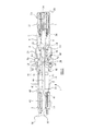
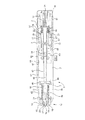
図1において断面にて示される注入装置1は、使用前の状態にて示されている。図2は同一の装置を示し、同様に使用前であるが、図1に対して90°にて断面化されている。
The
図1及び2を参照すると(両図にすべての符号が示されているわけではない)、注入装置1は体部又はハウジング2を備えており、これは3つの部分を有する。これらは(装置1の近位端から遠位端への順に)、本体10、中間体13及びシュラウド保持部15であり、本体10は近位本体部11と遠位本体部12に細分化される。これらの部分は一体として形成可能である。ハウジング2はスリーブ様の注射器キャリア82を保持または収容し、次に注射器キャリア82は注射器20を保持している。注射器20は流体22を収容するための概して筒状の容器部24と、針26と、を備えている。針は容器部24の内部と連通しており、そのため、流体22は針26を通じて放出されうる。栓28は近位端にて容器部24に挿入されている。このことは、容器部24の近位端からの流体22の外部への漏出を防止する。注射器20はバネ23によって近位端に向かって付勢される。しかし、このバネは比較的弱い。当初、針26は針鞘29により保護されている。
With reference to FIGS. 1 and 2 (not all symbols are shown in both figures), the
注入装置1の遠位端に安全キャップ又は針鞘リムーバー30が設けられている。この安全キャップはハウジング2のシュラウド保持部15により保持されている。その近位端の方に安全キャップは針鞘29の近位端を越えて引っ掛けられ、そのため、安全キャップ30が取り外されると、針鞘も取り外される。
A safety cap or
注入装置1の遠位端には針受32又は「ロックアウト・シュラウド」も設けられている。この針受は限定された範囲にわたり注入装置の縦軸に沿って移動可能である。しかし、当初、針受32は覆われており、安全キャップ30により移動を阻止されている。一旦、安全キャップ30が取り外されると(下記に説明するように)、針受30は移動することが可能となる。
The distal end of the
注入装置1の近位端の方にはプランジャ40が設けられ、これは、遠位部41及び近位部42を有する。プランジャはバネ50により遠位方向へ付勢される。この付勢は比較的強く、バネ23により付与される付勢よりもはるかに強力である。
A
注入装置1の最近位端には発射ボタン・組立品51が設けられている。その構造及び機能については以下に説明する。
A firing button /
注入装置1の操作の中核原理及び大部分の構造は、国際公開第03/011378号パンフレットに開示されている技術に酷似している。原則的に、この先行文献におけるように、安全キャップ30(及び針鞘29)の除去後、針受32はバネ34により付与される付勢のため、遠位方向に延長する。次に、注入装置1の遠位端が患者の皮膚に押圧される。このことが、バネ34の付勢に逆らって針受32を近位方向に押し動かす。しかし、この動作の間、針26は針受30の遠位端を越えて突出しない。
The core principle and most structure of the operation of the
先行開示された技術におけるように、発射ボタンが押されると、プランジャは解放され、遠位方向に移動可能となる。プランジャ40の前面45が栓28に接触すると、遠位方向におけるプランジャの連続移動は、初めに注射器20(即ち、栓28のみではない)を遠位方向に移動させる。この理由は、容器部24に対して栓28を遠位方向に移動させるのに必要な力が、注射器20全体を遠位方向に移動させるのに必要な力よりも大きいためである(このために、容器部24の内面は外周リブ又は他の摩擦増大構造体を備えることができる)。この注射器20の移動時に、針26は患者の皮膚を貫通する。最終的に、注射器20の遠位方向への移動は停止するが、プランジャ40は依然として遠位方向へ更に移動することが可能である。これにより、栓28は容器部24に対して遠位方向に移動され、これは、流体22が容器部24から針26を通じて患者に放出されるということである。従って、注射器20(全体として)の移動及び注射器20内の栓28の移動は、栓28に力を及ぼすプランジャ40によってもたらされる。注射器20に力を及ぼして注射器を移動させるプランジャ40の部分(遠位端面45)が、流体を放出するために注射器に力を及ぼして栓28を移動させるプランジャの部分と同一であることを理解されよう。プランジャ40が遠位方向へのその移動を停止すると、注入操作は完了している。次に、使用者は注入部位から針を抜去するため、注入装置1を近位方向に移動させることができる。注入装置1が患者の皮膚から抜去されると、針受32はバネ34により付与される付勢によって遠位方向に移動される。次に、針受32は遠位位置で、装置を安全な状態にロックする。次に、注入装置1は処分することができる。
As in the previously disclosed technique, when the firing button is pressed, the plunger is released and allowed to move in the distal direction. When the
先行開示された注入装置と対照的に、図1及び2に示される注入装置は複数の付加的特徴を有する。最も注目すべきことは、これらの付加的特徴が、注入される放出量を調節するための調節手段とプライミング機能であることである。 In contrast to the previously disclosed injection devices, the injection device shown in FIGS. 1 and 2 has a number of additional features. Most notably, these additional features are the adjustment means and priming function for adjusting the amount of injected injection.
調節手段は、主に、遠位プランジャ部41により保持されたストップ部材44から成る。ストップ部材44は、好ましい実施形態では、遠位プランジャ部41の外周面上の雄ネジ43と協働する雌ネジを備える。更に、ストップ部材44は46において遠位ハウジング部12の内面にキー嵌合されている。ストップ部材44が遠位プランジャ部41とねじ係合し、且つ遠位ハウジング部12にキー嵌合された(例えば、スプライン又は類似物によって、図示せず)状態にて、遠位プランジャ部41がその縦軸の周りを回転すると、ストップ部材44は遠位又は近位方向に移動する。
The adjusting means mainly comprises a
遠位プランジャ部41は調節リング48によって回転可能である。調節リング48はプランジャ40の遠位部41の比較的大きな径の近位部49にキー嵌合されている。このことは、調節リング48の回転時に、遠位プランジャ部41が同じ回転を実行するが、遠位プランジャ部41が調節リング48から独立してプランジャ軸に平行な方向に実質的に自由に移動できるということである。遠位プランジャ部41は、近位プランジャ部42に対して実質的に自由に回転できるように、遠位プランジャ部41の近位部49は近位プランジャ部42の遠位部47と係合しているが、近位部49は、近位プランジャ部42と同様に、遠位又は近位方向に移動する必要がある。
The
調節リング48は近位本体部11及び遠位本体部12の間に位置する。窓14は、近位本体部11及び遠位本体部12が接触する、本体10の反対側に設けられている。
The
注入装置1は概して楕円形の断面を有する。窓14は、楕円形の中心からの距離が短い、楕円形の「両側」に設けられている。本体は、楕円形の中心からの距離が最大の、楕円形の「両側」にて連続している。これは、近位本体部11及び遠位本体部12を有する本体10が一体として形成(例えば、成形)可能であり、更に、調節リング48が本体10内に固定保持されながら窓14を通じて突出可能であるということである。
The
注入される放出量を調節するため、使用者は調節リング48を回転することができ、これにより、プランジャ40の遠位部41を回転させる。既述のように、これにより、ストップ部材44の軸位置が遠位プランジャ部41に沿って設定される。この軸位置を設定することにより、使用者は、プランジャがどの程度まで容器部24内に突出することを許容されているのかを判断することができる。この理由は、ストップ部材44が容器部24の近位端と接触する際、注入プロセス時の遠位方向でのプランジャの移動が停止するためである。遠位プランジャ部41に沿ったストップ部材44の軸位置(注入操作の開始前)は、遠位本体部12に設けられた更なる窓16を通じて使用者によって観察可能である。窓16に対してストップ部材44の設定位置にどの放出量が対応するのかを使用者に示すため、窓16に好適な標示を設けてもよい。
To adjust the amount of discharge injected, the user can rotate the
図1及び2は概して同じ状態の注入装置1を示すが、これらの2図ではストップ部材44の位置が異なることに留意されよう。詳細な説明を不明瞭にすることがないように、図1ではストップ部材44は近位方向に移動されている。
1 and 2 show the
次に、注入装置1のプライミング機能の説明に入るが、遠位ハウジング部12に2つのプライミングボタン70が設けられている(プライミング機能は1つのみのプライミングボタンで果たせられうるが、2つのプライミングボタンが好ましいということに留意すべきである)。プライミングボタン70は、窓18の長さにより決定する短距離上を注入装置1の縦軸と平行に摺動可能である。各プライミングボタン70の半径方向内側に突起部72が設けられており、この突起部は、容器部24を囲う注射器キャリア82の係合構造体80と係合する。突起部72と係合構造体80との協働は、初めに、注射器キャリア82がプライミングボタン70についての軸移動に対してロックされる、ことを意味する。次に、容器部24は注射器キャリア82に十分に固定されており、これは、注射器20もプライミングボタン70についての軸移動に対してロックされる、ことを意味する。プライミングボタンは偶発的プライミングを防止できるように形成されうる。例えば、プライミングボタン70は、近位方向に移動可能となる前に、押し下げねばならないように、留め具又は類似物で形成されうる(図示せず)。
Next, the priming function of the
注射器20をプライミングするため、使用者は遠位端が上方を向くように注入装置1を垂直に保持するであろう。次に、使用者はプライミングボタン70が窓18の近位端と接触するまでプライミングボタン70を近位方向(即ち、下方)に移動させる。注射器キャリア82及び注射器20は同じ近位側移動を行う。この近位側移動の結果として、栓28は、栓28の近位端が遠位プランジャ部41の遠位端45と接触するため、容器部24に対して遠位方向に押し動かされる。従って、容器部24内に含まれる如何なる空気も針26を通じて放出される(おそらく、少量の流体22も)。
To prime the
注射器20及び注射器キャリア82が近位方向に移動する際、注射器キャリア82は注射器の軸の周りをわずかに旋回する。この旋回は注射器キャリア82の近位端におけるカム構成によって果たされる。カム構成は、注射器キャリア82の近位端におけるカム面と、対応するカム面であって、遠位本体部12の内側に設けられた突起部又はリブ90の遠位端に設けられたカム面と、を備えている。これらのカム面が互いに沿って接触・摺動するため、注射器キャリア82は旋回する。この旋回は、注射器キャリア82における内部突起部72及び係合構造体80が周方向で制限されているので、注射器キャリア82が(従って、注射器20も)プライミングボタン70についての軸移動に対して、もはやロックされないという効果を有する。このことは、注射器キャリア82が一旦回転すると、係合構造体80が注入操作を阻止または阻害しないように内部突起部72を自由に通過することができることを意味する。プライミング時に、注射器20は注射器キャリア82と共に回転しうるが、これは必須ではない。
As
プライミング機能が実行される方法は、まず、プライミング操作が実行されないと、通常、注入操作が実行できないということを意味する。それは、プライミング操作が実行されないと、注射器20がプライミングボタン70に対してロックされているため、注射器20が遠位方向に移動できず、プライミングボタン70もまた、窓18の遠位端と接触するため、プライミングボタン70が遠位方向に移動することを阻止されているためである。
The method by which the priming function is executed means that the injection operation cannot normally be executed unless the priming operation is executed. That is, if the priming operation is not performed, the
好ましい実施形態では、突起部又はリブ90並びにプライミングボタン70の大部分の構造体(好ましくはプライミングボタン70のすべての構造体、それらの内部突起部72は別にして)は、遠位本体部12の拡大径部に収容される。これにより、一旦プライミング操作が完了すると、プランジャ40が遠位方向に移動する際、突起部又はリブ90並びにプライミングボタン70がストップ部材44に干渉しないことが確実となりうる。
In a preferred embodiment, the protrusions or
しかし、別の実施形態では、このような遠位本体部12の拡大径部は設けられず、突起部又はリブ90並びにプライミングボタン70の大部分の構造体は遠位本体部12内に突出する。それらの実施形態では、プランジャ40及びストップ部材44が遠位方向に移動する際、ストップ部材44が突起部90及びプライミングボタン70を通過できるように、ストップ部材44は突起部90(及びプライミングボタン70)の外周位置において凹部を備えている。従って、プランジャ40と突起部90又はプライミングボタン70との干渉は回避可能である。ストップ部材44における凹部(図示せず)は、本体10に対してストップ部材44をキー嵌合するための凹部及びスプライン構成の一部として一般的に用いられうる。
However, in another embodiment, such an enlarged diameter portion of the
中間体13は使用者が容器24を観察できるように反対側に2つの観察窓9を備える。好ましい実施形態では、観察窓9、窓14及び窓16は、すべてハウジング2の同一側に設けられる。各種の窓9,14及び16について、反対側にある窓が2つ設けられることが好ましいが、装置1は、1つのみ又は3つ以上の各種の窓9,14及び16で形成してもよい。
The intermediate body 13 includes two
次に、発射ボタン構成51について説明するが、別の発射構成が用いられうることを理解されよう。発射ボタン構成51は発射ボタン52を備えており、発射ボタン52は、近位本体部11の近位端により保持されるとともに、近位本体部11の近位端内にて摺動可能である。しかし、当初の位置では発射ボタン52は摺動可能ではない。この理由は次のようになる。近位プランジャ部42の近位端において、58によって示される外側に突出する歯又はプランジャ保持かぎ状突起を備えた、2つ又はそれ以上の指状体が、設けられている。これらの外側に突出する歯58は肩部19に当接しており、肩部19は近位本体部11に固定され、または近位本体部11に対して一体形成される。これにより、近位プランジャ部42は遠位方向に移動することを阻止される。発射ボタン52の中央部に安全タブ56が設けられており、安全タブ56の遠位端も肩部19に当接している。これにより、安全ボタン52は押されることを回避される。注入装置が使用される際、使用者は安全タブ56を引きはがし(これは、容易に切断される薄形架橋部57により発射ボタン52に結合している)、発射ボタン52から安全タブ56を取り外す。これにより、発射ボタン52はバネ54の付勢に逆らって遠位方向に押し下げられることが可能となる。発射ボタン52は少なくとも1つの内部突起部59、好ましくは環状突起部59を備えている。突起部59は、歯58が肩部19を通過してしまえるように、近位プランジャ部41の近位端における指状体を一緒に締め付けるように配置される。従って、プランジャ40は解放され、これにより、注入操作を実施することが可能となる。
Next, although the
注入操作の完了時に、一連のロッキングかぎ状突起61が一連のハウジングかぎ状突起17を通過して遠位方向に移動しているように、注射器キャリア82は遠位方向に移動している。ハウジングかぎ状突起17は中間体部13の内面に設けられ、一方、ロッキングかぎ状突起61は注射器キャリア82と一体形成された可撓性脚部60に設けられている。注入操作が完了した後、ロッキングかぎ状突起61は、ハウジングかぎ状突起17に係合して注射器キャリア82が近位方向に移動することを阻止できるように、外側に突出している。
At the completion of the injection operation, the
ロッキングかぎ状突起61及びハウジングかぎ状突起17は以下の目的を有する。注入装置1が患者の皮膚に押圧されると、針受32は近位方向に移動している(図1及び2に示す位置へと、針受32は、バネ34により付与される付勢により、安全キャップ30が取り外されると即座に遠位方向に移動してしまうため)。注入操作時に注射器キャリア82が遠位方向に移動すると、脚部60の遠位端62はハウジングかぎ状突起17の近位面を傾斜台として用いて内側に移動する。これにより、脚部60は針受32の近位側に取り付けられた保護脚部38の間及び保護脚部38の中を通って摺動することが可能となる(脚部60が保護脚部38の中に/の中を通って突出できるように、保護脚部38は開口部37を備えている)。最終的に、注射器キャリア82が遠位方向への移動を完了すると、中間体13のストップ機構92に対してストップする注射器キャリア82のストップ面91により、脚部60は保護脚部38の間で停止する。注入操作後、注入装置1が注入部位から抜去されると、針受32はバネ34により付与される付勢により遠位方向に移動する。この間、保護脚部38は脚部60の遠位端62を通過して遠位方向に摺動し、注射器キャリア82は軸方向に移動しないが、脚部60はもはや保護脚部38によって内側に付勢されないため外側に移動する。一旦脚部60が外側に移動してしまうと、ロッキングかぎ状突起61は、ハウジングかぎ状突起17とほぼ同じ半径位置にあるが、ハウジングかぎ状突起17よりもわずかに遠位となる。これは、ロッキングかぎ状突起61がハウジングかぎ状突起17に係合する位置を越えて注射器キャリア82が近位方向に移動できないということである。
The locking
一旦脚部60が外側に移動してしまうと、針受32を近位方向に移動させる試みがたとえなされたとしても、そのとき、保護脚部38の近位端は脚部60の遠位端62に当接する。このこと(ロッキングかぎ状突起61とハウジングかぎ状突起17の係合のため、注射器キャリア82は近位方向への移動を阻止される)のため、針受は更に近位方向に移動することができない。これにより、注入装置1が使用された後、針26が針受32の遠位端を越えて突出されえないことが確実となる。
Once the
注入装置1は特に使用が簡便である。注入操作を行うには、使用者は遠位端から開始して注入装置1に沿って「操作手順を上昇させる」であろう。初めに、使用者は安全キャップ30を取り外すであろう。次に、使用者はプライミングボタン70によって注射器をプライミングし、次に、調節リング48を回転させて所望の放出量を設定し、次に、安全タブ56を取り外し、次に、注入装置を皮膚に押圧し、次に、発射ボタン52を押すであろう。注入操作後、使用者は皮膚から注入装置1を抜去し、装置を処分するであろう。
The
注入装置1は最小限の改変により様々な注射器径(即ち、サイズ)を収容することも可能である。より小さい径の注射器の使用を所望する場合、注射器キャリア82は注射器を収容するための比較的小さな内径を有する必要がある。より大きい径の注射器を使用するのであれば、注射器キャリア82の内径はより大きくする必要がある。従って、注入装置と共に用いるために異なる内径を有する様々な注射器キャリア82を提供することができる。注入装置の他のすべての部分は如何なる注射器径に対しても同じでよい(勿論、遠位プランジャ部の径は、プランジャが容器部24内に突出できるように、十分に小さい必要がある)。これにより、注入装置1のすべての部品(注射器キャリア82は別として)は、低減したコストで大量に製造することが可能となる。
The
本発明について、一例として好ましい実施形態を用いて説明してきたが、本発明が図1及び2を参照して述べた実施形態のすべての特徴を有する装置に限定されるものではないということを理解されよう。特に、放出量調節機構がそれ自体で有用であって、他種の注入装置に関連して用いられうるということを理解されよう。 Although the present invention has been described by way of example with a preferred embodiment, it is understood that the present invention is not limited to an apparatus having all the features of the embodiment described with reference to FIGS. Let's do it. In particular, it will be appreciated that the dose control mechanism is useful by itself and can be used in connection with other types of infusion devices.
次に、図3から16を参照して本発明の第二の実施形態について述べる。第二の実施形態の多くの特徴及び操作原理の主要部は、図1及び2を参照して述べた第一の実施形態のものに対応し、または類似し、従って、必ずしも再度詳細には述べない。図1及び2における対応する特徴に類似する図3から16における特徴は100〜199の符号を有し、一方、構造又は位置が図1及び2におけるものに必ずしも類似しない特徴は200以降の符号を有する。 Next, a second embodiment of the present invention will be described with reference to FIGS. The main features of the many features and operating principles of the second embodiment correspond to or are similar to those of the first embodiment described with reference to FIGS. 1 and 2, and are therefore not necessarily described in detail again. Absent. Features in FIGS. 3-16 that are similar to the corresponding features in FIGS. 1 and 2 have a reference number from 100 to 199, while features that are not necessarily similar in structure or position to those in FIGS. Have.
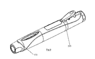
図3は第二の実施形態による注入装置の斜視図を示す。これは、中間体113及び近位本体部111を有するハウジングを備えている。中間体113は一方向歯450(図13に示す)又は他の「スナップ機構」によって近位本体部111に対して保持されうる。注入装置の遠位端に安全キャップ130が配置される。中間体113において注射器観察窓109が形成され、近位本体部111において放出量表示窓116が設けられている。両観察窓とも開放された状態におくことが可能であるが、装置の内部を保護するため、透明材で覆われることが好ましい。
FIG. 3 shows a perspective view of an injection device according to the second embodiment. This includes a housing having an
プライミング、放出量調節及びトリガー機能は、第一の実施形態のものと多少異なる。注入装置の近位端にプライミングボタン及び放出量ダイアルの複合体200が設けられている。プライミングボタン200上にプライミング調整矢印205が付されている。トリガー(又は発射ボタン)300は近位本体部111に沿って横方向に体部に装着されている。
The priming, release amount adjustment and trigger functions are slightly different from those of the first embodiment. At the proximal end of the infusion device, a priming button and
図4及び5は側面及び上面からの第二の実施形態による注入装置を示す。 4 and 5 show an injection device according to a second embodiment from the side and top.
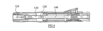
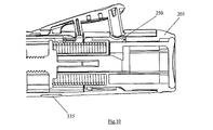
図6の断面図は注入装置の内部構造を示す。第一の実施形態におけるように、注入装置は、液体122が入っている注射器120、注射器120の遠位側に装着された針126、栓128及びプランジャ140を備えている。
6 shows the internal structure of the injection device. As in the first embodiment, the infusion device comprises a
図7に示すように、注射器キャリア182はハウジング内に、概して近位本体部111内に配置されている。注射器キャリア182も遠位方向に移動する際にのみ注射器120が遠位方向に移動できるように、注射器キャリア182は注射器120を保持する。
As shown in FIG. 7, the
図8は注入装置の近位部の構造を更に詳細に示す。プライミングボタン200は近位本体部111内にて摺動可能に保持される。これは、スナップ歯260によってハウジングの外部へ近位方向に摺動することを阻止される。例えば、ハウジングの周りに等間隔にてこれらのスナップ歯が3つ設けられうる。しかし、後述するように、当初、プライミングボタン200は遠位方向に移動することも阻止される。これも後述するように、当初、プライミングボタン200の角度移動も、例えば、30°の移動に制約される。バネ150はプライミングボタン200の遠位面とプランジャ140の近位面との間で圧縮されている。従って、プランジャ140は遠位方向に付勢されている。しかし、プランジャ140は、遠位方向に移動することを阻止されている。これは、プランジャ140が、外側に突出する歯158を有する2つの指状体に、固定されている又は一体形成されているためである。(歯158は、図2に示す近位プランジャ部42の2つの指状体及び歯58に多少類似している。)図8では明示されないが、歯158は、プライミングボタン200の近位面上に「引っ掛けられている」。
FIG. 8 shows in more detail the structure of the proximal portion of the infusion device. The
その遠位端において、プライミングボタン200は、非円形通路580を形成しており、非円形通路580は、好ましくは矩形断面を有している。指状体(即ち、プランジャ140)が通路580に対して実質的に回転できないように、プランジャの指状体は、通路580に対応する断面を有しており、通路580を通過する。従って、プランジャ140はプライミングボタン200に角度的にロックされる。
At its distal end, the
発射ブロック210はプライミングボタン200の一部を成す。図8に示す実施形態では、発射ブロックは、プライミングボタン200のトリムキャップ214に成形され、可撓性脚部215によってトリムキャップ214の近位部に結合している。
Firing block 210 forms part of
半径方向内側に発射ブロック210は“V”形の切欠きを備え、即ち、装置の軸に垂直な断面図では、発射ブロックは概して“V”形を有する。歯158の近位端は“V”形内に収容されている。
Radially inward, firing
図9にも示すように、トリガー300はハウジングに旋回可能に結合されている。図9に示すように、トリガーは、リング335を備えることができ、リング335は、近位本体部111に沿ってほぼ中間点にて装置の外側周りの凹部内に取り付けられている。再度図8を参照すると、注射器キャリア解放ピン310はトリガー300に沿ってほぼ中間点から半径方向内側に突出している。発射ピン320はトリガー300の近位端近傍から、これも半径方向内側に突出している。原則として、トリガー300が内側に旋回し及び/又は屈曲することができるように、トリガー300は形成されている。トリガー300は、当初、プライミングボタン200の遠位部によって、旋回及び/又は屈曲を阻止されている。プライミングボタン200は、発射ピン320の内側の移動路をブロックしている。トリガー300は、発射ピン320の半径方向内端から近位方向に突出する歯330により、所定の位置に保持されている。
As also shown in FIG. 9, the
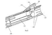
注射器キャリア182はハウジング内に配置される。図15により明瞭に示すように、注射器キャリア182はその近位端近傍に開口部又は凹部560を備える。架橋部550は開口部又は凹部560に隣接して近位側に位置する。図8に示すように、近位本体部111上に半径方向内側に形成された歯570は、開口部又は凹部560内に突出している。架橋部550の遠位面は歯570の近位面に当接し、そのため、注射器キャリア182は遠位方向に移動することを阻止される。注射器キャリア182は歯570により保持されている間、遠位方向に全く移動できないことが好ましいが、注射器キャリア182が極く限定された範囲で遠位方向に移動できるように、歯570と架橋部550との間に小間隙を設けることも可能であろう。
A
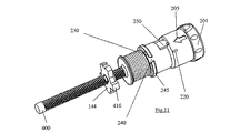
第一の実施形態におけるように、プランジャ140は雄ネジ軸を有し、そこへ雌ネジストップ部材144がねじ込まれる。図11に更に詳細に示すように、ストップ部材144は、注射器キャリア182の一部に沿って軸方向に延在する内部リブ555にガイドされる少なくとも1つの突起部410を有する。ストップ部材144が注射器キャリア182に対して回転することを阻止されるように、少なくとも2つの突起部410及びリブ555が設けられることが好ましい。従って、プランジャ140の回転時に、ストップ部材144はプランジャ140のネジ部に沿って軸方向に移動する。
As in the first embodiment, the
次に、第二の実施形態の操作について述べる。初めに、使用者は単に遠位方向に引っ張ることにより、または回転させてから遠位方向に引っ張ることにより、安全キャップ130を取り外すであろう。安全キャップ130の近位端と中間体部113の遠位端との間にカム131が形成される。これは、針鞘(図1及び2における部材29を参照)が注射器120に固着した場合に生じうる特定の大きな力を打ち消すのに役立ちうる。第一の実施形態と対照的に、安全キャップ130の除去後、遠位方向に移動する針受はない。針126は、図15に更に詳細に示すシュラウド132によって、また、シュラウド132内に保護された状態にある。
Next, the operation of the second embodiment will be described. Initially, the user will remove the safety cap 130 by simply pulling in the distal direction or by rotating and then pulling in the distal direction. A
プライミング時に注射器120から空気を放出できるように、安全キャップ130はプライミング前に取り外す必要がある。
Safety cap 130 must be removed prior to priming so that air can be released from
上述のように、当初、プライミングボタン200は遠位方向に移動することを阻止されている(後述する)。安全キャップ130を取り外した後、使用者はプライミングボタン200を約30°旋回させるであろう。この旋回後、プライミングボタンは遠位方向に限定された程度まで移動することが可能である(この遠位方向への移動の詳細については後述する)。遠位方向への移動時に、プランジャ140に当接するプライミングボタン200はプランジャ140を遠位方向に押し動かす。注入装置が概して垂直位置に保持され、その遠位端が上向きであると想定すると、プランジャが栓128を注射器120内に更に移動させるため、注射器120はプランジャ140の遠位方向への移動時にプライミングされる。適切なプライミングをなすためには、初期状態にてプランジャ140の遠位面が栓128の近位面に近接または当接していることが好ましい。プライミング時に、上述のように、それ自体遠位方向に移動することを阻止されている注射器キャリア182内に、注射器120が保持されているため、注射器はハウジングに対して移動しない。その代わり、プランジャ140はハウジングに対して移動する。
As described above, initially, the
プライミング後、注入装置は図9に示す状態にあり、これは、安全キャップ130が取り外され、プライミングボタン200が遠位方向に移動したことを示す。
After priming, the infusion device is in the state shown in FIG. 9, indicating that the safety cap 130 has been removed and the
次に、使用者は必要な放出量を設定するであろう。一旦装置がプライミングされると、使用者はプライミングボタン200の近位端における放出量ダイアル201(図10〜12を参照)を十分に回転させることができる。放出量ダイアル201を回転させることにより、矩形通路580を備えているプライミングボタン200全体が回転する。プランジャ140が矩形通路580に回転式にロックされるため、プランジャも回転する。このため、次に、ストップ部材144が軸方向に移動する。ストップ部材144が注射器120に向かって移動して近接するほど、プランジャ140が注射器120内に突出できる程度は少なくなり、即ち、減少するのは分配される放出量となる。
The user will then set the required release amount. Once the device is primed, the user can fully rotate the discharge dial 201 (see FIGS. 10-12) at the proximal end of the
放出量が設定された後、使用者は注入装置の遠位端を患者の皮膚上の所望の注入部位に対して保持するであろう(患者は使用者と同一でよい)。 After the dose is set, the user will hold the distal end of the infusion device against the desired infusion site on the patient's skin (the patient may be the same as the user).
トリガー300がハウジングに向かって旋回できるように、プライミングボタン200は、発射ピン320に位置合わせされる必要がある窓250と共に形成される。放出量ダイアルが「適正な」位置にあることを使用者により良く示すため(即ち、窓250が発射ピン320に位置合わせされるように)、図11に示すように、プライミングボタン200は1つ又はそれ以上のリブ220を備えることができ、図13に示すように、リブ220は近位主要ハウジング部111における1つ又はそれ以上の凹部222に受けられる。
The
更に、位置合わせされると、窓250と発射ピン320の位置合わせを示す、近位主要ハウジング部及び放出量ダイアル201上の標示を設けてもよい。
In addition, an indication on the proximal main housing portion and the
一旦窓250が発射ピン320に位置合わせされると、使用者はトリガー300を押し下げることができる。トリガー300が押し下げられると、注射器キャリア解放ピン310は架橋部550を押し下げ、注射器キャリア解放ピン310は半径方向内側に移動し、そのため、架橋部550は、もはや近位主要ハウジング部111の歯570により保持されない。これは、注射器キャリア(及びこれと共に注射器)が遠位方向に移動できるということである。更に、トリガー300が内側に旋回すると、トリガー300は発射ブロック210も内側に押し動かす。発射ブロック210の内向き移動は指状体158の近位端をまとめて圧迫し、そのため、指状体158はもはや矩形通路580の内縁を超えて横方向に突出せず、即ち、プランジャ140はもはや遠位方向に移動することを阻止されない。従って、第一の実施形態に類似する実際の注入操作が開始できるように、圧縮バネ150に蓄えられた力がプランジャ140を遠位方向に推進する。プランジャ140は遠位方向に移動すると、栓128に力を及ぼす。注射器120に対して栓128を移動させるのに必要な力は、注射器120及び注射器キャリア182を遠位方向に移動させるのに必要な力よりも大きいため、当初、プランジャ140の移動は実質的に注射器120から何ら薬剤を放出せずに注射器及び注射器キャリアを遠位方向に移動させるのみである。注射器キャリア解放ピン310が歯570から注射器キャリア182を解放しているため、注射器キャリア182は遠位方向に自由に移動できる。プランジャ及び注射器キャリアの遠位方向への移動は、注射器キャリア182の遠位面が図14に示すガイドリブ510に当接するまで続く。バネ150はプランジャ140に、従って、栓128に力を及ぼし続け、そのため、今や栓128はストップ部材144が注射器20の近位端によって停止するまで注射器120に対して遠位方向に移動する。従って、薬剤122は患者の皮膚内に注入される。
Once the
次に、使用者は皮膚から注入装置を抜去し、装置を処分するであろう。 The user will then remove the infusion device from the skin and dispose of the device.
図14〜16により明瞭に示すように、針受132は2本の注射器キャリア・バネ500によって注射器キャリア182に結合している。これら2本の圧縮バネは注射器120に沿って横方向に配置される。これらは、針受132及び注射器キャリア182の一方又は好ましくは両方と一体成形されることが好ましい。注入操作時に注射器キャリア182が近位方向に移動する際、注射器キャリア・バネ500は圧縮され、従って、針受132を遠位方向に付勢する。しかし、針受132は患者の皮膚に対して保持されているため、注入操作時に遠位方向に移動することはできない。しかし、一旦注入装置が患者の皮膚から取り外されると、注射器キャリア・バネ500は針受132を遠位方向に押し動かし、そのため、その遠位端は針126の遠位端よりも前方に遠位方向に突出し、そのため、針は針受132に取り囲まれる。針受132は、ハウジングかぎ状突起525と協働するように構成されたロックアウト脚部520を横方向に備え(図16)、そのため、一旦ロックアウト脚部520がハウジングかぎ状突起525を通過すると、針受132は近位方向への移動を阻止される。これは、使用者を事故による負傷から保護するのに役立つ。
As shown more clearly in FIGS. 14-16, the
図14に示すように、注射器キャリア・バネ500をガイドし、且つこれらが注入操作の終了時に針受132を確実に遠位方向へ移動させるため、注射器キャリア・バネ500に対して横方向にガイドリブ510が設けられている。
As shown in FIG. 14, guide ribs transverse to the
図15は注入装置の2つの更なる特徴を示す。第一に、注射器キャリア182の遠位側半部分に横方向に1つ又はそれ以上の切欠き530が設けられ、これらは、ハウジングの内面に形成された対応するリブを受容するように構成される。これは、注射器キャリアがハウジング内で回転することを阻止する。
FIG. 15 shows two additional features of the infusion device. First, one or
第二に、注射器キャリア182に複数の放出量表示窓540が設けられる。放出量表示窓540は、図15に示す実施形態において小三角形から成っている。もし、ストップ部材(及び放出量表示部)144の外側面が、好ましいように、例えば、赤色のような容易に識別可能な色を有する場合、放出量表示窓540は、個々に「ハイライト表示」される。放出量表示部144はこの色に成形され、または塗装されうる。放出量表示部144が三角形540下を通過すると、放出量表示部144と同じ軸位置にある放出量表示窓540により、放出量が示される。放出量表示窓540に隣接して注射器キャリア上に数字又は他の記号を付してもよい。
Second, the
図11を参照すると、プランジャ140の遠位端はネジ状でなく、即ち、非ネジ部400を有することが特に好ましい。これは、プランジャ140の遠位部もネジ状である実施形態と比較した際、プランジャ140の遠位端と栓128の近位面との境界面において、より均一な圧力分布を可能とするのに役立つ。
Referring to FIG. 11, it is particularly preferred that the distal end of the
放出量表示部144はプランジャ140上に(そのまま)成形されることが特に好ましい。成形工程中に2つの部分が接着しないように、放出量表示部144の組成はプランジャ140の組成と異なることが好ましい。放出量表示部144をプランジャ140上に成形することは3つの利点を有する。第一に、プランジャ140の遠位端が非ネジ状では、放出量表示部144をプランジャ140上にその遠位端から通すことは本質的に不可能である。第二に、プランジャ軸全体がネジ状にされても、放出量表示部144をプランジャ140上に成形することは、放出量表示部144をプランジャ140に沿って適正な初期位置に配置することを容易にしうる。第三に、プランジャ140のネジを多条ネジとして形成することが好ましいため、放出量表示部144がプランジャ140の遠位端からプランジャ軸上に通されるとすると、放出量表示部144の「適正な」ネジの条数を見出さすことがより困難となりうる。放出量表示部144をプランジャ140上に成形することは、この課題を解決する。
It is particularly preferable that the discharge
次に、第二の実施形態のプライミングボタン200の移動に対する初期の制限について述べる。
Next, initial restrictions on the movement of the
プライミングボタンは、プライミングボタン200から半径方向外側に突出するリング245を備えている(図11を参照)。このリング245は、通過ロック凹部230及び隣接するゲートウェイ240により、外周方向で中断されている。外周方向における通過ロック凹部230の範囲は、ゲートウェイ240の範囲よりも大きい。好ましい実施形態では、通過ロック凹部は約30°の角度にわたって伸びている。近位主要ハウジング部111の内面にプライミングボタン・ロッキングリブ270(図13を参照)が設けられている。このプライミングボタン・ロッキングリブ270は、類似形状及び寸法のゲートウェイ240を通過することができる。しかし、プライミングボタン・ロッキングリブ270がゲートウェイ240を通過することができるのは、これらが位置合わせしている場合のみである。注入装置の初期状態では、プライミングボタン・ロッキングリブ270はゲートウェイ240と正しく位置合わせされていない。しかし、当初、プライミングボタン・ロッキングリブ270の近位端は、通過ロック凹部230内に、図11では最上部になる通過ロック凹部230の周端部近傍に位置している。リング245の一部がプライミングボタン・ロッキングリブ270の近位端面に当接するため、プライミングボタン200は遠位方向に移動できない。しかし、ゲートウェイ240がプライミングボタン・ロッキングリブ270に位置合わせされるまで、プライミングボタン200は約30°の角度(通過ロック凹部の長さに対応)にわたり旋回可能である。
The priming button includes a
プライミングボタンがプライミングのための適正な位置に旋回したことを示すため、プライミングボタンにプライミング調整矢印205(図3を参照)が設けられている。近位主要ハウジング部111に、対応する標示を設けることができ、その表示を用いて矢印205が位置合わせできる。
A priming adjustment arrow 205 (see FIG. 3) is provided on the priming button to indicate that the priming button has pivoted to the proper position for priming. The proximal main housing part 111 can be provided with a corresponding marking, which can be used to align the
一旦プライミングボタン200が旋回すると、プライミング操作を実行することができる。
Once the
プライミング操作時に、プライミングボタン200は固定停止部まで遠位方向に移動され、その結果、リング245の近位端はプライミングボタン・ロッキングリブ270の遠位端のちょっと遠位の位置へ移動する。ゲートウェイ240及びプライミングボタン・ロッキングリブ270の遠位部は概して台形の形状を有し、それらの遠位端における広がりはそれらの近位端における広がりよりも大きい。特に、一旦プライミング操作が実行されると、プライミングボタン200が初期状態に向かって近位方向に移動できないように、ゲートウェイ240の近位端の幅はプライミングボタン・ロッキングリブ270の遠位端の幅よりも小さい。プライミングボタン・ロッキングリブ270がゲートウェイ240を通過するときは、ゲートウェイ240は若干拡張する。このために、リング245は軽度に可撓性である。
During the priming operation, the
近位主要ハウジング部111及びプライミングボタン200の外周に、1つ又はそれ以上のこのような通過ロック凹部230、プライミングボタン・ロッキングリブ270及びゲートウェイ240が、設けられうる。例えば3つである。
One or more such pass lock recesses 230, priming button and locking
第二の実施形態では、発射ピン320及び注射器キャリア解放ピン310を備えているトリガーは、一体成形品であることが好ましい。トリガー300が架橋部550を歯570から解放し、発射ブロック210を押し下げる発射ピン320により、(ほぼ)同時に装置を発射するように、第二の実施形態のトリガー300は構成されている。発射ブロック210が、解放される注射器キャリア182と実質的に同時に押し下げられることが好ましいが、これは不可欠ではない。発射ブロック210の押し下げは、注射器キャリア182の解放後に、ある程度遅延しても可能である。しかし、第二の実施形態による注入装置では、遅くとも圧縮バネ150がプランジャ140を遠位方向に移動させる時には、注射器キャリア182が解放されることが、保証されている。
In the second embodiment, the trigger comprising the
第二の実施形態では、注射器キャリア182を解放し、且つ注入装置を発射するのはトリガー300であるということは注目に値する。一部の従来技術の注入装置と対照的に、注射器キャリアの解放はプランジャ140を遠位方向に移動させず、また、プランジャの遠位方向への移動も注射器キャリア182の解放を生じさせない。これらの2つの作用が互いに影響を及ぼすことなく、これらの両作用を引き起こすのはトリガー300である。
It is noteworthy that in the second embodiment, it is the
次に、第三の実施形態について述べる。これは第二の実施形態に密接に基づき、従って、ここでは相違点のみについて述べる。図18に示す断面図及び図17における斜視図は図8に示す図に酷似している。ここでも発射ブロック210は、プランジャ140の指状体158の近位端を一緒に締め付けるための“V”形輪郭211で形成される。しかし、第三の実施形態のトリムキャップ214は、発射ブロック210に取り付けられるとともに注入装置を横断して延長する横断部213を備える。ブロック212は横断部213から遠位方向に延長し、プランジャ140の指状体158の近位端間の間隔内に一部が突出する。従って、ブロック212は、初期状態及びプライミングされた状態において、例えば、注入装置を落下させた場合に生じうるような、プランジャ140の指状体158の近位端が互いに向かって移動することを、阻止する。トリガーが内側に旋回され、発射ピン320が発射ブロック210に力を及ぼすと、ブロック212は発射ブロック210と共に移動し、そのため、ブロック212はもはやプランジャ140の指状体158の近位端間の間隔内に突出しない。従って、注入装置はトリガー300によって適切に発射されることが可能であるが、偶発的な発射は本質的に阻止される。
Next, a third embodiment will be described. This is closely based on the second embodiment, so only the differences will be described here. The cross-sectional view shown in FIG. 18 and the perspective view in FIG. 17 are very similar to the view shown in FIG. Again, the
好ましい実施形態の説明では、注射器キャリア82及び182を参照したが、特許請求の範囲では、「容器キャリア」という用語が用いられる。これは、上述のように、本発明が、必ずしも注射器ではない容器から物質を放出する装置にも同様に適用可能でありうるということを考慮に入れるためである。
In the description of the preferred embodiment, reference has been made to
本発明は、上述した好ましい実施形態の点から述べられたが、これらの実施形態は単に例示するものであり、また、特許請求の範囲はそれらの実施形態に限定されるものではないということを理解する必要がある。当業者であれば、本開示に照らし、添付の特許請求の範囲内に含まれるように考慮された改変及び代替をなすことが可能である。本明細書で開示または例示された各特徴は、単独であろうと、本明細書で開示または例示された他の任意の特徴と任意適切に組み合わせたものであろうと、本発明に組み込まれうる。 Although the present invention has been described in terms of the preferred embodiments described above, it is to be understood that these embodiments are merely illustrative and that the claims are not limited to those embodiments. Need to understand. Those skilled in the art will be able to make modifications and alternatives in view of the present disclosure, which are considered to fall within the scope of the appended claims. Each feature disclosed or exemplified herein can be incorporated into the present invention, whether alone or in any appropriate combination with any other feature disclosed or exemplified herein.
Claims (63)
容器を収容または保持するように構成された、体部と、
体部の少なくとも一部に対して移動可能であって、体部の前記一部に対して容器を移動させるために、容器に力を及ぼすように構成された、プランジャと、
を備えており、
プランジャが、容器から物質の少なくとも一部を放出するようにも構成されており、
物質送達装置が、容器から放出される物質の量を調節するための調節手段を備えている、
ことを特徴とする、物質送達装置。 A substance delivery device for use with a container containing a substance,
A body configured to contain or hold the container;
A plunger that is movable with respect to at least a portion of the body and configured to exert a force on the container to move the container relative to the portion of the body;
With
The plunger is also configured to release at least a portion of the substance from the container;
The substance delivery device comprises adjusting means for adjusting the amount of substance released from the container;
A substance delivery device.
請求項1に記載の物質送達装置。 The plunger is configured to exert a force on the closure of the container to move the container;
The substance delivery device according to claim 1.
請求項2に記載の物質送達装置。 The only part of the container configured to contact the plunger to move the container is a stopper,
The substance delivery device according to claim 2.
請求項1から5のいずれか一項に記載の物質送達装置。 The adjusting means comprises a stop member mounted to the plunger;
The substance delivery device according to any one of claims 1 to 5.
ストップ部材が、
プランジャの回転時に、プランジャの軸に沿って軸方向に移動するように、
a)プランジャに対して装着されており、
b)ガイド手段と協働するように構成されている、
請求項4に記載の物質送達装置。 The body further comprises guide means for cooperating with the stop member;
Stop member
As the plunger rotates, it moves axially along the plunger axis.
a) is attached to the plunger;
b) configured to cooperate with the guide means;
The substance delivery device according to claim 4.
請求項4又は5に記載の物質送達装置。 The plunger is configured to project into the container when releasing the portion of the substance, and the release of the substance is stopped by a stop member contacting the container;
The substance delivery device according to claim 4 or 5.
請求項1から6のいずれか一項に記載の物質送達装置。 The adjusting means comprises rotating means for rotating the plunger about the axis of the plunger;
The substance delivery device according to any one of claims 1 to 6.
請求項7に記載の物質送達装置。 The rotating means is keyed to the plunger and the rotating means does not substantially impede movement of the plunger parallel to the plunger axis;
The substance delivery device according to claim 7.
請求項1から9のいずれか一項に記載の物質送達装置。 Furthermore, a priming means for priming the container is provided,
10. The substance delivery device according to any one of claims 1 to 9.
請求項10に記載の物質送達装置。 The user will operate or manipulate the same components of the substance delivery device in order to prime the substance delivery device and adjust the amount of release.
The substance delivery device according to claim 10.
容器を収容または保持するように構成された、体部と、
体部の少なくとも一部に対して移動可能であって、体部の前記一部に対して容器を移動させるために、容器に力を及ぼすように構成された、プランジャと、
を備えており、
プランジャが、容器から物質の少なくとも一部を放出するようにも構成されており、
物質送達装置が、容器をプライミングするためのプライミング手段を備えている、
ことを特徴とする、物質送達装置。 A substance delivery device for use with a container containing a substance,
A body configured to contain or hold the container;
A plunger that is movable with respect to at least a portion of the body and configured to exert a force on the container to move the container relative to the portion of the body;
With
The plunger is also configured to release at least a portion of the substance from the container;
The substance delivery device comprises priming means for priming the container;
A substance delivery device.
請求項10から12のいずれか一項に記載の物質送達装置。 The priming means comprises moving means for moving the container towards the plunger;
The substance delivery device according to any one of claims 10 to 12.
請求項10から12のいずれか一項に記載の物質送達装置。 The priming means comprises moving means for moving the plunger relative to the part of the body part while the container is substantially stationary relative to the part of the body part;
The substance delivery device according to any one of claims 10 to 12.
請求項13に記載の物質送達装置。 The moving means comprises a movable member configured to engage the container to move the container toward the plunger;
14. A substance delivery device according to claim 13.
請求項15に記載の物質送達装置。 Upon completion of the priming operation, the movable member is configured to be released from the container.
The substance delivery device according to claim 15.
請求項16に記載の物質送達装置。 Configured so that at least a portion of the container is pivoted about the axis of the container upon completion of the priming operation;
17. A substance delivery device according to claim 16.
請求項17に記載の物質送達装置。 The body part includes a cam surface for turning at least a part of the container.
18. A substance delivery device according to claim 17.
請求項1から18のいずれか一項に記載の物質送達装置。 Furthermore, the container is provided,
The substance delivery device according to any one of claims 1 to 18.
請求項19に記載の物質送達装置。 When the container moves toward the plunger, the container includes a cam surface for turning the at least part of the container.
20. A substance delivery device according to claim 19.
請求項10から18のいずれか一項に直接または間接的に従属する、請求項19又は20に記載の物質送達装置。 The container comprises an engagement structure that allows the priming means to engage the container, the engagement structure being non-uniform in the outer circumferential direction;
21. A substance delivery device according to claim 19 or 20 directly or indirectly dependent on any one of claims 10-18.
請求項19から21のいずれか一項に記載の物質送達装置。 The force that the plunger needs to exert on the container to move the container relative to the portion of the body may be exerted on the container to release the portion of material. Less than the required force,
The substance delivery device according to any one of claims 19 to 21.
請求項2に間接的に従属する、請求項22に記載の物質送達装置。 The container is formed with at least one structure configured to increase the force required to move the stopper relative to the container;
23. A substance delivery device according to claim 22, which is indirectly dependent on claim 2.
請求項19から23のいずれか一項に記載の物質送達装置。 The container comprises a container carrier and a container part, the container part comprises a substance, and the container carrier holds the container part;
24. A substance delivery device according to any one of claims 19 to 23.
請求項19から24のいずれか一項に記載の物質送達装置。 In addition, a needle is provided, the needle and the container forming a syringe,
25. A substance delivery device according to any one of claims 19 to 24.
請求項1から18のいずれか一項に記載の物質送達装置。 Furthermore, a carrier for holding the container is provided,
The substance delivery device according to any one of claims 1 to 18.
プランジャと、
プランジャの実質的に遮られない移動を制限するための、プランジャに対して装着されたストップ部材と、
プランジャを、プランジャの縦軸の周りで回転させるための回転手段と、
を備えており、
ストップ部材が、
プランジャの回転時にプランジャの軸に沿って軸方向に移動するように、
a)プランジャに対して装着されており、
b)横方向ガイド手段と協働するように構成されている、
ことを特徴とする、調節機構。 An adjustment mechanism for adjusting the amount of substance released by the substance delivery device, comprising:
A plunger,
A stop member mounted to the plunger for limiting substantially unobstructed movement of the plunger;
Rotating means for rotating the plunger about the longitudinal axis of the plunger;
With
Stop member
To move axially along the plunger axis as the plunger rotates,
a) is attached to the plunger;
b) configured to cooperate with the lateral guide means;
An adjustment mechanism characterized by that.
請求項27に記載の調節機構。 The substance delivery device comprises a container for containing or holding the substance to be released, and the transverse guide means comprises at least part of said container;
28. The adjustment mechanism according to claim 27.
請求項28に記載の調節機構。 The lateral guide means comprises an opening in the container, and a portion of the stop member is configured to protrude into or through the opening;
30. The adjusting mechanism according to claim 28.
請求項28又は29に記載の調節機構。 The container comprises a container carrier configured to hold a container portion containing said substance, and lateral guide means are formed in the container carrier;
30. An adjustment mechanism according to claim 28 or 29.
請求項27から30のいずれか一項に記載の調節機構。 The plunger has a male screw shape, the stop member has a female screw shape, and the stop member includes key fitting means for key fitting to the lateral guide means.
The adjusting mechanism according to any one of claims 27 to 30.
請求項27から31のいずれか一項に記載の調節機構。 The rotating means is keyed to the plunger and the rotating means does not substantially impede movement of the plunger parallel to the axis of the plunger;
32. The adjustment mechanism according to any one of claims 27 to 31.
ネジ軸と、
自らに対するネジ軸の回転時に、自らがネジ軸に沿って且つネジ軸に対して軸方向に移動するように、ネジ軸上又はネジ軸の周りに成形された部材と、
を備えている、
ことを特徴とする、機構。 A mechanism for use in a substance delivery device comprising:
A screw shaft;
A member formed on or around the screw shaft such that when the screw shaft rotates with respect to itself, the screw shaft moves along the screw shaft and in the axial direction with respect to the screw shaft;
With
A mechanism characterized by that.
請求項33に記載の機構。 The distal end of the shaft is not threaded,
34. A mechanism according to claim 33.
請求項33又は34に記載の機構。 The screw of the shaft is a multi-thread
35. A mechanism according to claim 33 or 34.
請求項33から35のいずれか一項に記載の機構。 The shaft is a plunger or forms part of the plunger;
36. A mechanism according to any one of claims 33 to 35.
請求項33から36のいずれか一項に記載の機構。 The member is a stop member for limiting a substantially unobstructed movement of the shaft;
37. A mechanism according to any one of claims 33 to 36.
請求項33から37のいずれか一項に記載の機構。 The member is configured to regulate the amount of substance released by the substance delivery device;
38. A mechanism according to any one of claims 33 to 37.
請求項33から38のいずれか一項に記載の機構。 The member is configured to indicate the amount of substance released by the substance delivery device;
A mechanism according to any one of claims 33 to 38.
容器を収容するように構成された体部と、
体部の少なくとも一部に対して移動可能であって、体部の前記一部に対して容器を移動させるために、容器に力を及ぼすように構成された、プランジャと、
少なくとも2つの異なる容器キャリアであって、各容器キャリアが、前記容器を保持するための受容構造体を有しており、前記容器を体部に保持するために体部内に位置するように構成された、少なくとも2つの異なる容器キャリアと、
を備えており、
プランジャが、容器から物質の少なくとも一部を放出するようにも構成されており、
前記2つの異なる容器キャリアの受容構造体が、様々なサイズ又は形状の容器を収容できるように様々なサイズ又は形状を有している、
ことを特徴とする、部品のキット。 A kit of parts suitable for forming a substance delivery device configured to be used with a container containing a substance,
A body configured to receive the container;
A plunger that is movable with respect to at least a portion of the body and configured to exert a force on the container to move the container relative to the portion of the body;
At least two different container carriers, each container carrier having a receiving structure for holding the container and configured to be located within the body part for holding the container on the body part And at least two different container carriers;
With
The plunger is also configured to release at least a portion of the substance from the container;
The two different container carrier receiving structures have various sizes or shapes to accommodate containers of various sizes or shapes;
A kit of parts characterized by that.
請求項40に記載の部品のキット。 The receiving structure comprises an opening through which the container can be inserted;
41. A kit of parts according to claim 40.
請求項41に記載の部品のキット。 The opening has a cylindrical hole,
42. A kit of parts according to claim 41.
請求項40から42のいずれか一項に記載の部品のキット。 Apart from the shape or size of the receiving structure, the container carriers are substantially identical,
43. A kit of parts according to any one of claims 40 to 42.
容器を収容または保持するように構成された、体部と、
容器の一部及び/又は容器に結合した針の少なくとも一部を覆うための、シュラウドと、
を備えており、
容器及びシュラウドが、それぞれの近位位置及び遠位位置間にて、体部に対して、移動可能であり、シュラウド及び容器を互いに対して付勢するための付勢手段が、シュラウド及び/又は容器と一体形成された、
ことを特徴とする、物質送達装置。 A container configured to contain or hold the material to be released;
A body configured to contain or hold the container;
A shroud to cover a portion of the container and / or at least a portion of the needle coupled to the container;
With
The container and the shroud are movable relative to the body between respective proximal and distal positions, and biasing means for biasing the shroud and the container relative to each other includes the shroud and / or Integrally formed with the container,
A substance delivery device.
請求項44に記載の物質送達装置。 The biasing means is integrally formed with both the shroud and the container;
45. A substance delivery device according to claim 44.
請求項44又は45に記載の物質送達装置。 The biasing means is configured to bias the shroud away from the container;
46. A substance delivery device according to claim 44 or 45.
請求項44から46のいずれか一項に記載の物質送達装置。 The container comprises a container carrier configured to hold a container portion containing the substance;
47. A substance delivery device according to any one of claims 44 to 46.
物質送達装置が、
放出される物質を収容または保持するように構成された、容器と、
容器を収容または保持するように構成された、体部と、
容器の一部及び/又は容器に結合した針の少なくとも一部を覆うためのシュラウドと、
を備えており、
容器及びシュラウドが、それぞれの近位位置及び遠位位置間にて、体部に対して、移動可能であり、
付勢組立品が、
シュラウド及び容器を互いに対して付勢するための付勢手段と、
前記シュラウド及び前記容器の少なくとも1つと、
を備えており、
付勢手段が、前記シュラウド及び前記容器の前記少なくとも1つと一体形成された、
ことを特徴とする、付勢組立品。 A biasing assembly for use in a substance delivery device comprising:
The substance delivery device
A container configured to contain or hold the material to be released;
A body configured to contain or hold the container;
A shroud for covering a portion of the container and / or at least a portion of the needle coupled to the container;
With
A container and a shroud are movable relative to the body between respective proximal and distal positions;
The biasing assembly is
Biasing means for biasing the shroud and the container against each other;
At least one of the shroud and the container;
With
A biasing means is integrally formed with the at least one of the shroud and the container;
A biasing assembly characterized by that.
請求項48に記載の付勢組立品。 A biasing assembly includes both the shroud and the container, and the biasing means is integrally formed with both the shroud and the container;
49. A biasing assembly according to claim 48.
容器を収容または保持するように構成された、体部と、
容器をプライミングするための手段であって、プライミング操作時に移動するように構成された可動部を備えている、プライミング手段と、
プライミング操作が実行されてしまう前に、更なる操作が実行されることを阻害または阻止するための、阻害又は阻止手段と、
を備えており、
更なる操作が、物質の放出及び/又は放出される物質の放出量の調節を含んでいる、
ことを特徴とする、物質送達装置。 A substance delivery device for use with a container containing a substance,
A body configured to contain or hold the container;
Means for priming the container, comprising a movable part configured to move during a priming operation;
Inhibiting or blocking means for inhibiting or preventing further operations from being performed before the priming operation has been performed;
With
Further operations include release of the substance and / or adjustment of the amount of released substance,
A substance delivery device.
物質送達装置が、放出される物質の放出量を調節するための調節手段を備えており、
調節手段の少なくとも一部が可動であり、
阻害又は阻止手段が、調節手段の前記可動部の移動路における障害物を備えている、
請求項50に記載の物質送達装置。 Further operations comprise adjusting the amount of released material,
The substance delivery device comprises an adjusting means for adjusting the amount of released substance;
At least part of the adjusting means is movable;
The inhibiting or blocking means comprises an obstacle in the moving path of the movable part of the adjusting means,
51. A substance delivery device according to claim 50.
請求項51に記載の物質送達装置。 Execution of the priming operation is configured to move the obstacle outside the moving path of the movable part of the adjusting means, or to move the obstacle outside the moving path of the movable part of the adjusting means. The
52. The substance delivery device of claim 51.
請求項51に記載の物質送達装置。 Performing the priming operation is configured to move the movable part of the adjusting means such that an obstacle is no longer present in the path of movement of the movable part of the adjusting means;
52. The substance delivery device of claim 51.
物質送達装置が物質の放出を誘発するためのトリガー手段を備えており、
トリガー手段の少なくとも一部が可動であり、
阻害又は阻止手段が、トリガー手段の前記可動部の移動路における障害物を備えている、
請求項50に記載の物質送達装置。 A further operation comprises the release of the substance,
The substance delivery device comprises trigger means for inducing the release of the substance;
At least part of the trigger means is movable,
The inhibition or prevention means comprises an obstacle in the movement path of the movable part of the trigger means,
51. A substance delivery device according to claim 50.
請求項54に記載の物質送達装置。 The execution of the priming operation is configured to move the obstacle out of the movement path of the movable part of the trigger means, or to move the obstacle out of the movement path of the movable part of the trigger means,
55. A substance delivery device according to claim 54.
請求項54に記載の物質送達装置。 The execution of the priming operation is configured to move the movable part of the trigger means such that an obstacle is no longer in the path of movement of the movable part of the trigger means;
55. A substance delivery device according to claim 54.
容器を収容または保持するように構成された、体部と、
容器をプライミングするための手段であって、プライミング操作時に非プライミング位置からプライミング位置へ移動するように構成された可動部を備えている、プライミング手段と、
プライミング位置から非プライミング位置へのプライミング手段の前記可動部の移動を阻害または阻止するための、阻害又は阻止手段と、
を備えている、
ことを特徴とする、物質送達装置。 A substance delivery device for use with a container containing a substance,
A body configured to contain or hold the container;
Means for priming the container, comprising a movable part configured to move from a non-priming position to a priming position during a priming operation;
Inhibiting or blocking means for inhibiting or preventing movement of the movable part of the priming means from a priming position to a non-priming position;
With
A substance delivery device.
容器を収容または保持するように構成された、体部と、
プランジャと、
第一の位置から第二の位置へ移動可能な、トリガーと、
を備えており、
トリガーが第一の位置にある間、容器の移動が阻害または阻止されており、
トリガーが、トリガーが第二の位置へ移動される際、
a)体部の少なくとも一部に対して容器を移動可能とするために、容器を解放し、
b)容器から物質の少なくとも一部を放出するために、プランジャが容器に力を及ぼすように、体部の前記一部に対してプランジャを移動させる、
ように構成された、
ことを特徴とする、物質送達装置。 A container configured to contain or hold the material to be released;
A body configured to contain or hold the container;
A plunger,
A trigger movable from a first position to a second position;
With
While the trigger is in the first position, the movement of the container is obstructed or prevented,
When the trigger is moved to the second position,
a) releasing the container in order to make it movable relative to at least a part of the body part;
b) moving the plunger relative to said part of the body so that the plunger exerts a force on the container to release at least a part of the substance from the container;
Configured as
A substance delivery device.
請求項58に記載の物質送達装置。 The trigger is configured to release the container when the trigger is moved to the second position and to move the plunger in such a way that the plunger does not move before the container is released;
59. A substance delivery device according to claim 58.
請求項58又は59に記載の物質送達装置。 The trigger is configured to release the container and move the plunger substantially simultaneously when the trigger is moved to the second position;
60. A substance delivery device according to claim 58 or 59.
請求項58から60のいずれか一項に記載の物質送達装置。 Release of the container does not require movement of the plunger,
61. A substance delivery device according to any one of claims 58 to 60.
トリガーが第二の位置にある時に、容器が第二の範囲内にて体部の前記一部に対して移動することができ、
第二の範囲が第一の範囲よりも広い、
請求項58から61のいずれか一項に記載の物質送達装置。 While the trigger is in the first position, the container can move relative to the part of the body part within the first range;
When the trigger is in the second position, the container can move relative to the part of the body part within the second range;
The second range is wider than the first range,
62. A substance delivery device according to any one of claims 58 to 61.
請求項62に記載の物質送達装置。 The first range is substantially zero,
63. A substance delivery device according to claim 62.
Applications Claiming Priority (4)
| Application Number | Priority Date | Filing Date | Title |
|---|---|---|---|
| GB0524978A GB2433032A (en) | 2005-12-08 | 2005-12-08 | Syringe with dose adjustment means |
| GB0524978.4 | 2005-12-08 | ||
| GB0617064A GB2433035A (en) | 2005-12-08 | 2006-08-30 | Substance delivery device |
| GB0617064.1 | 2006-08-30 |
Related Parent Applications (1)
| Application Number | Title | Priority Date | Filing Date |
|---|---|---|---|
| JP2008543918A Division JP5139996B2 (en) | 2005-12-08 | 2006-12-08 | Improvements related to substance delivery devices |
Publications (2)
| Publication Number | Publication Date |
|---|---|
| JP2012183322A true JP2012183322A (en) | 2012-09-27 |
| JP5520997B2 JP5520997B2 (en) | 2014-06-11 |
Family
ID=35735723
Family Applications (2)
| Application Number | Title | Priority Date | Filing Date |
|---|---|---|---|
| JP2008543918A Active JP5139996B2 (en) | 2005-12-08 | 2006-12-08 | Improvements related to substance delivery devices |
| JP2012103680A Active JP5520997B2 (en) | 2005-12-08 | 2012-04-27 | Improvements related to substance delivery devices |
Family Applications Before (1)
| Application Number | Title | Priority Date | Filing Date |
|---|---|---|---|
| JP2008543918A Active JP5139996B2 (en) | 2005-12-08 | 2006-12-08 | Improvements related to substance delivery devices |
Country Status (5)
| Country | Link |
|---|---|
| US (2) | US9308327B2 (en) |
| EP (7) | EP2340862B1 (en) |
| JP (2) | JP5139996B2 (en) |
| GB (2) | GB2433032A (en) |
| WO (1) | WO2007066152A2 (en) |
Cited By (15)
| Publication number | Priority date | Publication date | Assignee | Title |
|---|---|---|---|---|
| US8945063B2 (en) | 2009-03-20 | 2015-02-03 | Antares Pharma, Inc. | Hazardous agent injection system |
| US9144648B2 (en) | 2006-05-03 | 2015-09-29 | Antares Pharma, Inc. | Injector with adjustable dosing |
| US9180259B2 (en) | 2005-01-24 | 2015-11-10 | Antares Pharma, Inc. | Prefilled syringe jet injector |
| US9220660B2 (en) | 2011-07-15 | 2015-12-29 | Antares Pharma, Inc. | Liquid-transfer adapter beveled spike |
| US9333309B2 (en) | 2002-02-11 | 2016-05-10 | Antares Pharma, Inc. | Intradermal injector |
| US9364611B2 (en) | 2012-05-07 | 2016-06-14 | Antares Pharma, Inc. | Needle assisted jet injection device having reduced trigger force |
| US9393367B2 (en) | 2013-03-12 | 2016-07-19 | Antares Pharma, Inc. | Prefilled syringes and kits thereof |
| US9446195B2 (en) | 2011-07-15 | 2016-09-20 | Antares Pharma, Inc. | Injection device with cammed ram assembly |
| US9486583B2 (en) | 2012-03-06 | 2016-11-08 | Antares Pharma, Inc. | Prefilled syringe with breakaway force feature |
| US9561333B2 (en) | 2008-08-05 | 2017-02-07 | Antares Pharma, Inc. | Multiple dosage injector |
| US9707354B2 (en) | 2013-03-11 | 2017-07-18 | Antares Pharma, Inc. | Multiple dosage injector with rack and pinion dosage system |
| US9744302B2 (en) | 2013-02-11 | 2017-08-29 | Antares Pharma, Inc. | Needle assisted jet injection device having reduced trigger force |
| US9808582B2 (en) | 2006-05-03 | 2017-11-07 | Antares Pharma, Inc. | Two-stage reconstituting injector |
| US9867949B2 (en) | 2008-03-10 | 2018-01-16 | Antares Pharma, Inc. | Injector safety device |
| US9950125B2 (en) | 2012-04-06 | 2018-04-24 | Antares Pharma, Inc. | Needle assisted jet injection administration of testosterone compositions |
Families Citing this family (140)
| Publication number | Priority date | Publication date | Assignee | Title |
|---|---|---|---|---|
| GB2414406B (en) | 2004-05-28 | 2009-03-18 | Cilag Ag Int | Injection device |
| GB2414403B (en) | 2004-05-28 | 2009-01-07 | Cilag Ag Int | Injection device |
| GB2414401B (en) | 2004-05-28 | 2009-06-17 | Cilag Ag Int | Injection device |
| GB2414402B (en) | 2004-05-28 | 2009-04-22 | Cilag Ag Int | Injection device |
| GB2414775B (en) | 2004-05-28 | 2008-05-21 | Cilag Ag Int | Releasable coupling and injection device |
| GB2414409B (en) | 2004-05-28 | 2009-11-18 | Cilag Ag Int | Injection device |
| GB2414400B (en) | 2004-05-28 | 2009-01-14 | Cilag Ag Int | Injection device |
| GB2414399B (en) | 2004-05-28 | 2008-12-31 | Cilag Ag Int | Injection device |
| US7947017B2 (en) | 2004-11-22 | 2011-05-24 | Intelliject, Inc. | Devices, systems and methods for medicament delivery |
| US7648483B2 (en) | 2004-11-22 | 2010-01-19 | Intelliject, Inc. | Devices, systems and methods for medicament delivery |
| US11590286B2 (en) | 2004-11-22 | 2023-02-28 | Kaleo, Inc. | Devices, systems and methods for medicament delivery |
| US10737028B2 (en) | 2004-11-22 | 2020-08-11 | Kaleo, Inc. | Devices, systems and methods for medicament delivery |
| DK2058020T3 (en) | 2005-02-01 | 2013-01-07 | Intelliject Inc | Device for administering drug |
| GB2424838B (en) | 2005-04-06 | 2011-02-23 | Cilag Ag Int | Injection device (adaptable drive) |
| GB2424835B (en) | 2005-04-06 | 2010-06-09 | Cilag Ag Int | Injection device (modified trigger) |
| GB2425062B (en) | 2005-04-06 | 2010-07-21 | Cilag Ag Int | Injection device |
| GB2424836B (en) | 2005-04-06 | 2010-09-22 | Cilag Ag Int | Injection device (bayonet cap removal) |
| GB2427826B (en) | 2005-04-06 | 2010-08-25 | Cilag Ag Int | Injection device comprising a locking mechanism associated with integrally formed biasing means |
| DE602005018480D1 (en) | 2005-08-30 | 2010-02-04 | Cilag Gmbh Int | Needle device for a prefilled syringe |
| US20110098656A1 (en) | 2005-09-27 | 2011-04-28 | Burnell Rosie L | Auto-injection device with needle protecting cap having outer and inner sleeves |
| GB2438593B (en) | 2006-06-01 | 2011-03-30 | Cilag Gmbh Int | Injection device (cap removal feature) |
| GB2438591B (en) | 2006-06-01 | 2011-07-13 | Cilag Gmbh Int | Injection device |
| GB2438590B (en) | 2006-06-01 | 2011-02-09 | Cilag Gmbh Int | Injection device |
| GB2451665B (en) * | 2007-08-08 | 2012-09-26 | Cilag Gmbh Int | Injection device |
| GB2451662B (en) * | 2007-08-08 | 2012-09-19 | Cilag Gmbh Int | Injection device |
| CN101868273B (en) | 2007-10-02 | 2014-10-15 | 莱蒙德尔有限公司 | External drug pump |
| US9656019B2 (en) | 2007-10-02 | 2017-05-23 | Medimop Medical Projects Ltd. | Apparatuses for securing components of a drug delivery system during transport and methods of using same |
| GB0724906D0 (en) * | 2007-12-20 | 2008-01-30 | Ucb Pharma Sa | Auto-injector |
| GB2461086B (en) | 2008-06-19 | 2012-12-05 | Cilag Gmbh Int | Injection device |
| GB2461087B (en) | 2008-06-19 | 2012-09-26 | Cilag Gmbh Int | Injection device |
| GB2461084B (en) | 2008-06-19 | 2012-09-26 | Cilag Gmbh Int | Fluid transfer assembly |
| GB2461085B (en) | 2008-06-19 | 2012-08-29 | Cilag Gmbh Int | Injection device |
| GB2461089B (en) | 2008-06-19 | 2012-09-19 | Cilag Gmbh Int | Injection device |
| GB0814747D0 (en) * | 2008-08-13 | 2008-09-17 | Owen Mumford Ltd | Autoinjection devices |
| US7959598B2 (en) | 2008-08-20 | 2011-06-14 | Asante Solutions, Inc. | Infusion pump systems and methods |
| CN102448525B (en) * | 2009-04-03 | 2014-12-17 | Shl集团有限责任公司 | Medicament delivery device |
| US8585656B2 (en) * | 2009-06-01 | 2013-11-19 | Sanofi-Aventis Deutschland Gmbh | Dose setting mechanism for priming a drug delivery device |
| CN102548599B (en) | 2009-07-08 | 2014-07-23 | 诺沃-诺迪斯克有限公司 | Auto-priming injection device |
| US9265891B2 (en) * | 2009-09-30 | 2016-02-23 | Sanofi-Aventis Deutschland Gmbh | Assembly of a drug delivery device |
| EP2482893A1 (en) * | 2009-09-30 | 2012-08-08 | Sanofi-Aventis Deutschland GmbH | Drug delivery device |
| EP2482873A1 (en) | 2009-09-30 | 2012-08-08 | Sanofi-Aventis Deutschland GmbH | Drug delivery device |
| WO2011101379A1 (en) | 2010-02-18 | 2011-08-25 | Sanofi-Aventis Deutschland Gmbh | Auto-injector |
| CN103037922B (en) | 2010-06-03 | 2015-08-26 | Shl集团有限责任公司 | Medicament delivery device |
| EP2399634A1 (en) * | 2010-06-28 | 2011-12-28 | Sanofi-Aventis Deutschland GmbH | Needle safety arrangement and method for operating it |
| EP2399628A1 (en) * | 2010-06-28 | 2011-12-28 | Sanofi-Aventis Deutschland GmbH | Auto-injector |
| EP2399633A1 (en) * | 2010-06-28 | 2011-12-28 | Sanofi-Aventis Deutschland GmbH | Needle safety arrangement and method for operating it |
| EP2399629A1 (en) * | 2010-06-28 | 2011-12-28 | Sanofi-Aventis Deutschland GmbH | Auto-injector |
| EP2585138B1 (en) * | 2010-06-28 | 2016-04-20 | Sanofi-Aventis Deutschland GmbH | Auto-injector |
| EP2399635A1 (en) | 2010-06-28 | 2011-12-28 | Sanofi-Aventis Deutschland GmbH | Auto-injector |
| EP2399630A1 (en) * | 2010-06-28 | 2011-12-28 | Sanofi-Aventis Deutschland GmbH | Auto-injector |
| CN103179996B (en) * | 2010-08-31 | 2016-03-16 | Shl集团有限责任公司 | Medicament delivery device |
| GB201015799D0 (en) | 2010-09-21 | 2010-10-27 | Owen Mumford Ltd | Autoinjectors |
| EP2438940A1 (en) * | 2010-10-08 | 2012-04-11 | Sanofi-Aventis Deutschland GmbH | Auto injector with a torsion spring |
| EP2438941A1 (en) * | 2010-10-08 | 2012-04-11 | Sanofi-Aventis Deutschland GmbH | Auto injector with a torsion spring |
| USRE48593E1 (en) | 2010-12-21 | 2021-06-15 | Sanofi-Aventis Deutschland Gmbh | Auto-injector |
| EP2468330A1 (en) | 2010-12-21 | 2012-06-27 | Sanofi-Aventis Deutschland GmbH | Auto-injector |
| EP2468333A1 (en) | 2010-12-21 | 2012-06-27 | Sanofi-Aventis Deutschland GmbH | Auto-injector |
| GB2486693B (en) * | 2010-12-22 | 2016-05-18 | Owen Mumford Ltd | Autoinjectors and manufacturing systems thereof |
| US8627816B2 (en) | 2011-02-28 | 2014-01-14 | Intelliject, Inc. | Medicament delivery device for administration of opioid antagonists including formulations for naloxone |
| US9084849B2 (en) | 2011-01-26 | 2015-07-21 | Kaleo, Inc. | Medicament delivery devices for administration of a medicament within a prefilled syringe |
| US8939943B2 (en) | 2011-01-26 | 2015-01-27 | Kaleo, Inc. | Medicament delivery device for administration of opioid antagonists including formulations for naloxone |
| EP2709695B1 (en) * | 2011-05-19 | 2019-11-20 | Becton, Dickinson and Company | Injection device with automated substance combining feature |
| JP2014526369A (en) | 2011-09-22 | 2014-10-06 | アッヴィ・インコーポレイテッド | Automatic injection equipment |
| ES2556003T3 (en) | 2011-09-22 | 2016-01-12 | Abbvie Inc. | Automatic injection device |
| WO2013149186A1 (en) | 2012-03-30 | 2013-10-03 | Insulet Corporation | Fluid delivery device with transcutaneous access tool, insertion mechansim and blood glucose monitoring for use therewith |
| JP6254149B2 (en) * | 2012-04-13 | 2017-12-27 | ベクトン・ディキンソン・アンド・カンパニーBecton, Dickinson And Company | Micro infuser that automatically retracts the needle |
| CN104684604B (en) * | 2012-10-08 | 2018-06-05 | 特克法马许可公司 | Injection device with quantitative control device |
| GB2510098B (en) * | 2012-11-07 | 2019-10-16 | Surgical Innovations Ltd | Surgical instrument |
| US10321903B2 (en) * | 2012-11-07 | 2019-06-18 | Surgical Innovations Limited | Surgical instrument for dispensing a fluid |
| EP2919836A2 (en) * | 2012-11-13 | 2015-09-23 | IN.Tool ApS | Protective cap for a device |
| CN205019531U (en) * | 2012-12-26 | 2016-02-10 | 贝克顿·迪金森公司 | Syringe needle package is used to pen |
| US10238805B2 (en) * | 2013-04-23 | 2019-03-26 | Elcam Medical Agricultural Cooperative | Automatic injection device for administration of high viscosity medication |
| GB2515032A (en) | 2013-06-11 | 2014-12-17 | Cilag Gmbh Int | Guide for an injection device |
| GB2515039B (en) | 2013-06-11 | 2015-05-27 | Cilag Gmbh Int | Injection Device |
| GB2517896B (en) | 2013-06-11 | 2015-07-08 | Cilag Gmbh Int | Injection device |
| GB2515038A (en) | 2013-06-11 | 2014-12-17 | Cilag Gmbh Int | Injection device |
| EP2823841A1 (en) | 2013-07-09 | 2015-01-14 | Sanofi-Aventis Deutschland GmbH | Autoinjector |
| EP2823837A1 (en) * | 2013-07-09 | 2015-01-14 | Sanofi-Aventis Deutschland GmbH | Autoinjector |
| WO2015007814A1 (en) * | 2013-07-17 | 2015-01-22 | Sanofi | Priming configuration for a medical device and drug delivery device comprising a priming configuration |
| JP6525991B2 (en) * | 2013-07-17 | 2019-06-05 | サノフイSanofi | Assembly for a drug delivery device and method of operation thereof |
| WO2015026737A1 (en) * | 2013-08-19 | 2015-02-26 | Dr. Reddy's Laboratories, Ltd. | Selectable single dose auto-injector and methods of making and using same |
| GB2521212B (en) | 2013-12-13 | 2016-07-27 | Owen Mumford Ltd | Selectable dose injection device |
| EP2923714A1 (en) | 2014-03-28 | 2015-09-30 | Sanofi-Aventis Deutschland GmbH | Autoinjector triggered by skin contact |
| US9517307B2 (en) | 2014-07-18 | 2016-12-13 | Kaleo, Inc. | Devices and methods for delivering opioid antagonists including formulations for naloxone |
| EP3188772A4 (en) * | 2014-09-05 | 2018-08-01 | Min Wei | Automatic injection device with variable dosing |
| EP3247430B1 (en) | 2015-01-21 | 2021-09-15 | Antares Pharma, Inc. | Injection device having variable dosing |
| US10149943B2 (en) | 2015-05-29 | 2018-12-11 | West Pharma. Services IL, Ltd. | Linear rotation stabilizer for a telescoping syringe stopper driverdriving assembly |
| EP3316928B1 (en) | 2015-06-30 | 2022-10-19 | Kaleo, Inc. | Auto-injectors for administration of a medicament within a prefilled syringe |
| GB2541227A (en) * | 2015-08-13 | 2017-02-15 | Owen Mumford Ltd | Injector Device |
| GB2541915A (en) * | 2015-09-03 | 2017-03-08 | Owen Mumford Ltd | Medicament delivery devices |
| US9987432B2 (en) | 2015-09-22 | 2018-06-05 | West Pharma. Services IL, Ltd. | Rotation resistant friction adapter for plunger driver of drug delivery device |
| US10576207B2 (en) | 2015-10-09 | 2020-03-03 | West Pharma. Services IL, Ltd. | Angled syringe patch injector |
| US10086145B2 (en) * | 2015-09-22 | 2018-10-02 | West Pharma Services Il, Ltd. | Rotation resistant friction adapter for plunger driver of drug delivery device |
| JP7017512B2 (en) | 2015-10-09 | 2022-02-08 | ウェスト ファーマ サービシーズ イスラエル リミテッド | Bending fluid path type accessories for filled fluid containers |
| DE202015007351U1 (en) | 2015-10-22 | 2017-01-27 | Haselmeier Ag | injection device |
| PL227678B1 (en) * | 2015-12-22 | 2018-01-31 | Copernicus Spolka Z Ograniczona Odpowiedzialnoscia | Control and drive system for the device intended for injection and the device for making injections equipped with such a system |
| US10275573B2 (en) | 2016-01-13 | 2019-04-30 | Bigfoot Biomedical, Inc. | User interface for diabetes management system |
| JP6876046B2 (en) | 2016-01-14 | 2021-05-26 | ビッグフット バイオメディカル インコーポレイテッドBigfoot Biomedical, Inc. | Adjustment of insulin delivery amount |
| CN113041432B (en) | 2016-01-21 | 2023-04-07 | 西医药服务以色列有限公司 | Medicament delivery device comprising a visual indicator |
| WO2017127215A1 (en) | 2016-01-21 | 2017-07-27 | Medimop Medical Projects Ltd. | Needle insertion and retraction mechanism |
| CN111544704B (en) | 2016-01-21 | 2022-06-03 | 西医药服务以色列有限公司 | Force containment in autoinjectors |
| DK3429663T3 (en) * | 2016-03-15 | 2020-09-28 | Amgen Inc | REDUCING THE LIKELIHOOD OF GLASS BREAKING IN MEDICINE ADMINISTRATION DEVICES |
| US11389597B2 (en) | 2016-03-16 | 2022-07-19 | West Pharma. Services IL, Ltd. | Staged telescopic screw assembly having different visual indicators |
| USD818587S1 (en) | 2016-03-29 | 2018-05-22 | Abbevie Inc. | Automatic injection device |
| GB2549964A (en) * | 2016-05-04 | 2017-11-08 | Owen Mumford Ltd | Medicament delivery devices |
| WO2017191306A1 (en) * | 2016-05-06 | 2017-11-09 | Sanofi-Aventis Deutschland Gmbh | Drug delivery device |
| EP3646905B1 (en) | 2016-05-26 | 2021-06-23 | Insulet Corporation | Single dose drug delivery device |
| PL3108914T3 (en) * | 2016-07-07 | 2019-08-30 | Copernicus Sp. Z O.O. | Injection device for delivering a defined number of equal doses of a liquid substance |
| US20180015224A1 (en) | 2016-07-13 | 2018-01-18 | California Institute Of Technology | Dampers and Methods for Performing Measurements in an Autoinjector |
| JP6869327B2 (en) | 2016-08-01 | 2021-05-12 | ウェスト ファーマ サービシーズ イスラエル リミテッド | Anti-rotation cartridge |
| US10363372B2 (en) | 2016-08-12 | 2019-07-30 | Insulet Corporation | Plunger for drug delivery device |
| US10561797B2 (en) | 2016-08-14 | 2020-02-18 | Insulet Corporation | Drug delivery device with indicator |
| DK3519018T3 (en) * | 2016-09-27 | 2021-06-14 | Sanofi Aventis Deutschland | MEDICINE ADMINISTRATION DEVICE |
| US11452820B2 (en) * | 2016-09-27 | 2022-09-27 | Sanofi-Aventis Deutschland Gmbh | Medicament delivery device |
| WO2018067645A1 (en) | 2016-10-07 | 2018-04-12 | Insulet Corporation | Multi-stage delivery system |
| US10780217B2 (en) | 2016-11-10 | 2020-09-22 | Insulet Corporation | Ratchet drive for on body delivery system |
| WO2018107144A1 (en) * | 2016-12-09 | 2018-06-14 | Georgia Tech Research Corporation | Tissue lifting devices and methods of use |
| US10688244B2 (en) | 2016-12-23 | 2020-06-23 | Kaleo, Inc. | Medicament delivery device and methods for delivering drugs to infants and children |
| WO2018136699A1 (en) | 2017-01-19 | 2018-07-26 | Insulet Corporation | Cartridge hold-up volume reduction |
| US11771836B2 (en) | 2017-02-03 | 2023-10-03 | Norton Healthcare Limited | Assembly for a medication delivery device and medication delivery device |
| US11389594B2 (en) | 2017-02-03 | 2022-07-19 | Norton Healthcare Limited | Assembly for a medication delivery device and medication delivery device |
| EP3576821A1 (en) | 2017-02-03 | 2019-12-11 | Norton Healthcare Limited | Assembly for a medication delivery device and medication delivery device |
| EP3576822B1 (en) * | 2017-02-03 | 2021-12-08 | Norton Healthcare Limited | Assembly for a medication delivery device and medication delivery device comprising such an assembly |
| US10695485B2 (en) | 2017-03-07 | 2020-06-30 | Insulet Corporation | Very high volume user filled drug delivery device |
| EP3630226A1 (en) | 2017-05-30 | 2020-04-08 | West Pharma. Services Il, Ltd. | Modular drive train for wearable injector |
| US10973978B2 (en) | 2017-08-03 | 2021-04-13 | Insulet Corporation | Fluid flow regulation arrangements for drug delivery devices |
| US11280327B2 (en) | 2017-08-03 | 2022-03-22 | Insulet Corporation | Micro piston pump |
| US11786668B2 (en) | 2017-09-25 | 2023-10-17 | Insulet Corporation | Drug delivery devices, systems, and methods with force transfer elements |
| TWI678221B (en) | 2017-09-28 | 2019-12-01 | 瑞士商瑞健醫療股份有限公司 | Drive unit |
| USD928199S1 (en) | 2018-04-02 | 2021-08-17 | Bigfoot Biomedical, Inc. | Medication delivery device with icons |
| JP7284186B2 (en) | 2018-04-04 | 2023-05-30 | シェイリー エンジニアリング プラスチックス リミテッド | automatic syringe |
| KR20210016555A (en) * | 2018-05-24 | 2021-02-16 | 노파르티스 아게 | Automatic drug delivery device |
| US10874803B2 (en) | 2018-05-31 | 2020-12-29 | Insulet Corporation | Drug cartridge with drive system |
| EP3801682A1 (en) | 2018-06-06 | 2021-04-14 | Insulet Corporation | Linear shuttle pump for drug delivery |
| GB2577538B (en) * | 2018-09-28 | 2021-10-13 | Owen Mumford Ltd | Injection device fill volume management |
| AU2019390474B2 (en) | 2018-11-28 | 2023-03-30 | Insulet Corporation | Drug delivery shuttle pump system and valve assembly |
| US20210307913A1 (en) * | 2019-01-04 | 2021-10-07 | Nemera Szczecin Spolka Z Ograniczonaodpowiedzialnoscia | Injection device for delivering a defined number of equal doses of a fluid substance |
| EP4009936A4 (en) | 2019-08-09 | 2023-08-09 | Kaleo, Inc. | Devices and methods for delivery of substances within a prefilled syringe |
| US11369735B2 (en) | 2019-11-05 | 2022-06-28 | Insulet Corporation | Component positioning of a linear shuttle pump |
| EP4267218A1 (en) * | 2020-12-22 | 2023-11-01 | SHL Medical AG | Simple medicament delivery device |
Citations (2)
| Publication number | Priority date | Publication date | Assignee | Title |
|---|---|---|---|---|
| JP2003511157A (en) * | 1999-10-12 | 2003-03-25 | ノボ ノルディスク アクティーゼルスカブ | Air shot mechanism for electronic injection devices |
| JP2005025852A (en) * | 2003-07-01 | 2005-01-27 | Toshiba Corp | Disk storage device and head positioning control method |
Family Cites Families (49)
| Publication number | Priority date | Publication date | Assignee | Title |
|---|---|---|---|---|
| GB993309A (en) † | 1961-04-11 | 1965-05-26 | Express Injector Company Ltd | Improved hypodermic injector |
| US3785572A (en) * | 1972-05-25 | 1974-01-15 | Peabody Engineering Corp | Plastic lined spray nozzle |
| JPS55116620U (en) * | 1979-02-13 | 1980-08-18 | ||
| DE2907108A1 (en) | 1979-02-23 | 1980-09-04 | Basf Ag | METHOD FOR PRODUCING STORAGE-STABLE, PUMPABLE AND FLOWABLE ALUMOSILICATE SUSPENSIONS BY WET MILLING |
| EP0037696B1 (en) † | 1980-04-08 | 1984-05-23 | Greater Glasgow Health Board | Dispensing device |
| DE3134602C2 (en) * | 1981-09-01 | 1983-10-27 | Stahlgruber Otto Gruber GmbH & Co, 8000 MÜnchen | Method and device for producing a tube with a closure cap made of plastic |
| DE3645245C2 (en) * | 1986-11-14 | 1994-01-27 | Haselmeier Wilhelm Fa | Injection appliance |
| IL86799A (en) † | 1987-07-02 | 1993-03-15 | Kabi Pharmacia Ab | Method and device for injection |
| DD262803A1 (en) † | 1987-08-05 | 1988-12-14 | Transform Roentgen Matern Veb | INJECTION DEVICE |
| US4820275A (en) | 1987-12-21 | 1989-04-11 | Habley Medical Technology Corporation | Retractable needle syringe with integral spring |
| US4894054A (en) † | 1988-06-20 | 1990-01-16 | Miskinyar Shir A | Preloaded automatic disposable syringe |
| US5705112A (en) | 1989-07-14 | 1998-01-06 | Gram; Jes Tougaard | Procedure for the production of an assembled object |
| US5057086A (en) | 1990-07-30 | 1991-10-15 | Dillard Iii John A B | Safety syringe |
| DE4112259A1 (en) † | 1991-04-15 | 1992-10-22 | Medico Dev Investment Co | INJECTION DEVICE |
| US5176643A (en) | 1991-04-29 | 1993-01-05 | George C. Kramer | System and method for rapid vascular drug delivery |
| US5405362A (en) | 1991-04-29 | 1995-04-11 | The Board Of Regents For The University Of Texas System | Interactive external defibrillation and drug injection system |
| US5271744A (en) | 1991-04-29 | 1993-12-21 | George C. Kramer | System and method for rapid vascular drug delivery |
| FR2701211B1 (en) | 1993-02-08 | 1995-05-24 | Aguettant Lab | DOSING INSTRUMENT, ESPECIALLY INJECTION |
| GB9310163D0 (en) | 1993-05-18 | 1993-06-30 | Owen Mumford Ltd | Improvements relating to injection devices |
| US5833669A (en) * | 1993-05-27 | 1998-11-10 | Washington Biotech Corp. | Medicine injection syringe constructions |
| US5514097A (en) * | 1994-02-14 | 1996-05-07 | Genentech, Inc. | Self administered injection pen apparatus and method |
| DE29522418U1 (en) * | 1994-05-30 | 2003-05-08 | B D Medico S A R L | injection device |
| US6110149A (en) † | 1996-09-13 | 2000-08-29 | Novo Nordisk A/S | Syringe |
| US5843042A (en) * | 1996-11-06 | 1998-12-01 | Ren; Liang Chen | Oral medicine dispensing device having a metered syringe component and reservoir |
| US5846042A (en) | 1997-06-24 | 1998-12-08 | Sony Corporation | Fastener/shaft locking and adjustment apparatus |
| DE19740187C1 (en) † | 1997-09-12 | 1999-04-15 | Disetronic Licensing Ag | Dosing unit, e.g. for medicines |
| DK1003581T3 (en) * | 1998-01-30 | 2000-12-18 | Novo Nordisk As | Syringe |
| DE29818721U1 (en) | 1998-10-21 | 2000-03-02 | Medico Dev Investment Co | Injection device |
| SE9901366D0 (en) † | 1999-04-16 | 1999-04-16 | Pharmacia & Upjohn Ab | Injector device and method for its operation |
| ATE308354T1 (en) † | 1999-04-16 | 2005-11-15 | Becton Dickinson Co | PIN-SHAPED INJECTOR WITH FEATURES FOR AUTOMATIC SUBSTANCE COMBINATION |
| FR2815543B1 (en) † | 2000-10-19 | 2003-10-24 | Sedat | SELF-INJECTION SYRINGE OF AN EXTEMPORANEOUS MIXTURE |
| IL156245A0 (en) † | 2000-12-22 | 2004-01-04 | Dca Design Int Ltd | Drive mechanism for an injection device |
| US6645170B2 (en) † | 2001-03-05 | 2003-11-11 | Bioject Medical Technologies, Inc. | Simplified disposable needle-free injection apparatus and method |
| ES2236532T3 (en) | 2001-07-16 | 2005-07-16 | Eli Lilly And Company | MEDICINES DISPENSING DEVICE CONFIGURED TO BE PRIMED BY ROTATION AND WITH TRACTION / THRUST TO FUNCTIONALLY INJECT. |
| GB0118419D0 (en) | 2001-07-28 | 2001-09-19 | Owen Mumford Ltd | Improvements relating to injection devices |
| DE10163328B4 (en) | 2001-07-30 | 2005-08-11 | Tecpharma Licensing Ag | Administration device with anti-rotation device |
| US20050027255A1 (en) * | 2003-07-31 | 2005-02-03 | Sid Technologies, Llc | Automatic injector |
| DE20317377U1 (en) | 2003-11-03 | 2005-03-17 | B D Medico S A R L | injection device |
| DE10351596B4 (en) * | 2003-11-05 | 2007-10-11 | Tecpharma Licensing Ag | Autoinjector with variable dose |
| DE10351598A1 (en) * | 2003-11-05 | 2005-06-16 | Tecpharma Licensing Ag | Auto-injection device |
| EP1541185A1 (en) † | 2003-12-08 | 2005-06-15 | Novo Nordisk A/S | Automatic syringe with priming mechanism |
| ATE446112T1 (en) | 2003-12-18 | 2009-11-15 | Tecpharma Licensing Ag | TRIGGERABLE INJECTION DEVICE |
| US20050222539A1 (en) | 2004-03-30 | 2005-10-06 | Pediamed Pharmaceuticals, Inc. | Automatic injection device |
| DE102004019325A1 (en) * | 2004-04-21 | 2005-11-24 | Tecpharma Licensing Ag | Administration device with priming function |
| DE102004041151A1 (en) | 2004-08-25 | 2006-03-02 | Tecpharma Licensing Ag | Dosing device with flow control |
| US20060129122A1 (en) | 2004-12-06 | 2006-06-15 | Wyrick Ronald E | Method and apparatus for delivering epinephrine |
| DE102005022532A1 (en) * | 2005-05-17 | 2006-11-23 | Tecpharma Licensing Ag | Delivery device with forced priming |
| JP4834389B2 (en) † | 2005-11-29 | 2011-12-14 | 前田産業株式会社 | Injection device |
| US7650369B2 (en) | 2006-03-30 | 2010-01-19 | Fujitsu Limited | Database system management method and database system |
-
2005
- 2005-12-08 GB GB0524978A patent/GB2433032A/en not_active Withdrawn
-
2006
- 2006-08-30 GB GB0617064A patent/GB2433035A/en not_active Withdrawn
- 2006-12-08 EP EP11156319.3A patent/EP2340862B1/en not_active Expired - Fee Related
- 2006-12-08 US US12/096,675 patent/US9308327B2/en not_active Expired - Fee Related
- 2006-12-08 EP EP06820667A patent/EP1968670B1/en not_active Expired - Fee Related
- 2006-12-08 EP EP11156289.8A patent/EP2340863B1/en active Active
- 2006-12-08 EP EP13165538.3A patent/EP2620174B1/en active Active
- 2006-12-08 EP EP11156314.4A patent/EP2327438B1/en not_active Expired - Fee Related
- 2006-12-08 EP EP11156322.7A patent/EP2340864B2/en active Active
- 2006-12-08 EP EP11156303.7A patent/EP2327439B1/en not_active Expired - Fee Related
- 2006-12-08 WO PCT/GB2006/050441 patent/WO2007066152A2/en active Application Filing
- 2006-12-08 JP JP2008543918A patent/JP5139996B2/en active Active
-
2012
- 2012-04-27 JP JP2012103680A patent/JP5520997B2/en active Active
-
2016
- 2016-02-26 US US15/054,312 patent/US9849243B2/en active Active
Patent Citations (2)
| Publication number | Priority date | Publication date | Assignee | Title |
|---|---|---|---|---|
| JP2003511157A (en) * | 1999-10-12 | 2003-03-25 | ノボ ノルディスク アクティーゼルスカブ | Air shot mechanism for electronic injection devices |
| JP2005025852A (en) * | 2003-07-01 | 2005-01-27 | Toshiba Corp | Disk storage device and head positioning control method |
Cited By (45)
| Publication number | Priority date | Publication date | Assignee | Title |
|---|---|---|---|---|
| US9737670B2 (en) | 2002-02-11 | 2017-08-22 | Antares Pharma, Inc. | Intradermal injector |
| US9333309B2 (en) | 2002-02-11 | 2016-05-10 | Antares Pharma, Inc. | Intradermal injector |
| US9629959B2 (en) | 2005-01-24 | 2017-04-25 | Antares Pharma, Inc. | Prefilled syringe jet injector |
| US10478560B2 (en) | 2005-01-24 | 2019-11-19 | Antares Pharma, Inc. | Prefilled syringe injector |
| US9180259B2 (en) | 2005-01-24 | 2015-11-10 | Antares Pharma, Inc. | Prefilled syringe jet injector |
| US11446441B2 (en) | 2005-01-24 | 2022-09-20 | Antares Pharma, Inc. | Prefilled syringe injector |
| US11547808B2 (en) | 2006-05-03 | 2023-01-10 | Antares Pharma, Inc. | Two-stage reconstituting injector |
| US9808582B2 (en) | 2006-05-03 | 2017-11-07 | Antares Pharma, Inc. | Two-stage reconstituting injector |
| US10688250B2 (en) | 2006-05-03 | 2020-06-23 | Antares Pharma, Inc. | Two-stage reconstituting injector |
| US11471600B2 (en) | 2006-05-03 | 2022-10-18 | Antares Pharma, Inc. | Injector with adjustable dosing |
| US9144648B2 (en) | 2006-05-03 | 2015-09-29 | Antares Pharma, Inc. | Injector with adjustable dosing |
| US10543316B2 (en) | 2006-05-03 | 2020-01-28 | Antares Pharma, Inc. | Injector with adjustable dosing |
| US11684723B2 (en) | 2008-03-10 | 2023-06-27 | Antares Pharma, Inc. | Injector safety device |
| US9867949B2 (en) | 2008-03-10 | 2018-01-16 | Antares Pharma, Inc. | Injector safety device |
| US10709844B2 (en) | 2008-03-10 | 2020-07-14 | Antares Pharma, Inc. | Injector safety device |
| US11058824B2 (en) | 2008-08-05 | 2021-07-13 | Antares Pharma, Inc. | Multiple dosage injector |
| US9561333B2 (en) | 2008-08-05 | 2017-02-07 | Antares Pharma, Inc. | Multiple dosage injector |
| US10300212B2 (en) | 2008-08-05 | 2019-05-28 | Antares Pharma, Inc. | Multiple dosage injector |
| US11497753B2 (en) | 2009-03-20 | 2022-11-15 | Antares Pharma, Inc. | Hazardous agent injection system |
| US9750881B2 (en) | 2009-03-20 | 2017-09-05 | Antares Pharma, Inc. | Hazardous agent injection system |
| US8945063B2 (en) | 2009-03-20 | 2015-02-03 | Antares Pharma, Inc. | Hazardous agent injection system |
| US10555954B2 (en) | 2009-03-20 | 2020-02-11 | Antares Pharma, Inc. | Hazardous agent injection system |
| US10568809B2 (en) | 2011-07-15 | 2020-02-25 | Ferring B.V. | Liquid-transfer adapter beveled spike |
| US10279131B2 (en) | 2011-07-15 | 2019-05-07 | Antares Pharma, Inc. | Injection device with cammed RAM assembly |
| US9220660B2 (en) | 2011-07-15 | 2015-12-29 | Antares Pharma, Inc. | Liquid-transfer adapter beveled spike |
| US9446195B2 (en) | 2011-07-15 | 2016-09-20 | Antares Pharma, Inc. | Injection device with cammed ram assembly |
| US10478559B2 (en) | 2012-03-06 | 2019-11-19 | Antares Pharma, Inc. | Prefilled syringe with breakaway force feature |
| US9486583B2 (en) | 2012-03-06 | 2016-11-08 | Antares Pharma, Inc. | Prefilled syringe with breakaway force feature |
| US11602597B2 (en) | 2012-03-06 | 2023-03-14 | Antares Pharma, Inc. | Prefilled syringe with breakaway force feature |
| US11771646B2 (en) | 2012-04-06 | 2023-10-03 | Antares Pharma, Inc. | Needle assisted jet injection administration of testosterone compositions |
| US9950125B2 (en) | 2012-04-06 | 2018-04-24 | Antares Pharma, Inc. | Needle assisted jet injection administration of testosterone compositions |
| US10821072B2 (en) | 2012-04-06 | 2020-11-03 | Antares Pharma, Inc. | Needle assisted jet injection administration of testosterone compositions |
| US11446440B2 (en) | 2012-05-07 | 2022-09-20 | Antares Pharma, Inc. | Needle assisted injection device having reduced trigger force |
| US10905827B2 (en) | 2012-05-07 | 2021-02-02 | Antares Pharma, Inc. | Injection device with cammed ram assembly |
| US9364610B2 (en) | 2012-05-07 | 2016-06-14 | Antares Pharma, Inc. | Injection device with cammed ram assembly |
| US10357609B2 (en) | 2012-05-07 | 2019-07-23 | Antares Pharma, Inc. | Needle assisted jet injection device having reduced trigger force |
| US9364611B2 (en) | 2012-05-07 | 2016-06-14 | Antares Pharma, Inc. | Needle assisted jet injection device having reduced trigger force |
| US9744302B2 (en) | 2013-02-11 | 2017-08-29 | Antares Pharma, Inc. | Needle assisted jet injection device having reduced trigger force |
| US10881798B2 (en) | 2013-02-11 | 2021-01-05 | Antares Pharma, Inc. | Needle assisted injection device having reduced trigger force |
| US11813435B2 (en) | 2013-02-11 | 2023-11-14 | Antares Pharma, Inc. | Needle assisted injection device having reduced trigger force |
| US10610649B2 (en) | 2013-03-11 | 2020-04-07 | Antares Pharma, Inc. | Multiple dosage injector with rack and pinion dosage system |
| US9707354B2 (en) | 2013-03-11 | 2017-07-18 | Antares Pharma, Inc. | Multiple dosage injector with rack and pinion dosage system |
| US11628260B2 (en) | 2013-03-11 | 2023-04-18 | Antares Pharma, Inc. | Multiple dosage injector with rack and pinion dosage system |
| US9393367B2 (en) | 2013-03-12 | 2016-07-19 | Antares Pharma, Inc. | Prefilled syringes and kits thereof |
| US10675400B2 (en) | 2013-03-12 | 2020-06-09 | Antares Pharma, Inc. | Prefilled syringes and kits thereof |
Also Published As
| Publication number | Publication date |
|---|---|
| EP2340863B1 (en) | 2013-11-13 |
| EP2327439B1 (en) | 2013-07-31 |
| EP2340864B1 (en) | 2013-06-26 |
| EP2620174A1 (en) | 2013-07-31 |
| US9308327B2 (en) | 2016-04-12 |
| EP2620174B1 (en) | 2014-05-21 |
| EP2340862B1 (en) | 2013-07-17 |
| WO2007066152A3 (en) | 2007-08-23 |
| JP2009525059A (en) | 2009-07-09 |
| JP5139996B2 (en) | 2013-02-06 |
| EP2340863A2 (en) | 2011-07-06 |
| EP2340862A3 (en) | 2011-08-10 |
| WO2007066152A2 (en) | 2007-06-14 |
| EP2340862A2 (en) | 2011-07-06 |
| GB2433035A (en) | 2007-06-13 |
| EP2340864B2 (en) | 2021-10-13 |
| EP2340864A3 (en) | 2011-08-10 |
| US20160175528A1 (en) | 2016-06-23 |
| EP1968670A2 (en) | 2008-09-17 |
| EP2340863A3 (en) | 2011-08-10 |
| GB0617064D0 (en) | 2006-10-11 |
| EP2327438A1 (en) | 2011-06-01 |
| EP2327438B1 (en) | 2013-08-28 |
| US20100010454A1 (en) | 2010-01-14 |
| GB2433032A (en) | 2007-06-13 |
| EP1968670B1 (en) | 2011-05-18 |
| JP5520997B2 (en) | 2014-06-11 |
| EP2340864A2 (en) | 2011-07-06 |
| GB0524978D0 (en) | 2006-01-18 |
| EP2327439A1 (en) | 2011-06-01 |
| US9849243B2 (en) | 2017-12-26 |
Similar Documents
| Publication | Publication Date | Title |
|---|---|---|
| JP5520997B2 (en) | Improvements related to substance delivery devices | |
| US20240058535A1 (en) | Safety mechanism for an autoinjector | |
| US11484667B2 (en) | Medicament delivery device | |
| USRE49197E1 (en) | Injection device | |
| TWI626969B (en) | Medicament delivery device | |
| US20050085776A1 (en) | Injection device for administering a fluid product | |
| JP2016539741A (en) | Dose selectable injection device | |
| US10881797B2 (en) | Drive mechanism for an autoinjector | |
| JP2020511273A (en) | Medical Delivery Device Safety Assembly | |
| EP3423131B1 (en) | Automatic delivery device with end of injection indication device | |
| CN109310824B (en) | Medicament delivery device |
Legal Events
| Date | Code | Title | Description |
|---|---|---|---|
| A977 | Report on retrieval |
Free format text: JAPANESE INTERMEDIATE CODE: A971007 Effective date: 20130613 |
|
| A131 | Notification of reasons for refusal |
Free format text: JAPANESE INTERMEDIATE CODE: A131 Effective date: 20130618 |
|
| A601 | Written request for extension of time |
Free format text: JAPANESE INTERMEDIATE CODE: A601 Effective date: 20130917 |
|
| A602 | Written permission of extension of time |
Free format text: JAPANESE INTERMEDIATE CODE: A602 Effective date: 20130920 |
|
| A521 | Request for written amendment filed |
Free format text: JAPANESE INTERMEDIATE CODE: A523 Effective date: 20131008 |
|
| TRDD | Decision of grant or rejection written | ||
| A01 | Written decision to grant a patent or to grant a registration (utility model) |
Free format text: JAPANESE INTERMEDIATE CODE: A01 Effective date: 20140311 |
|
| A61 | First payment of annual fees (during grant procedure) |
Free format text: JAPANESE INTERMEDIATE CODE: A61 Effective date: 20140407 |
|
| R150 | Certificate of patent or registration of utility model |
Ref document number: 5520997 Country of ref document: JP Free format text: JAPANESE INTERMEDIATE CODE: R150 |
|
| R250 | Receipt of annual fees |
Free format text: JAPANESE INTERMEDIATE CODE: R250 |
|
| R250 | Receipt of annual fees |
Free format text: JAPANESE INTERMEDIATE CODE: R250 |
|
| R250 | Receipt of annual fees |
Free format text: JAPANESE INTERMEDIATE CODE: R250 |
|
| R250 | Receipt of annual fees |
Free format text: JAPANESE INTERMEDIATE CODE: R250 |
|
| R250 | Receipt of annual fees |
Free format text: JAPANESE INTERMEDIATE CODE: R250 |
|
| R250 | Receipt of annual fees |
Free format text: JAPANESE INTERMEDIATE CODE: R250 |
|
| R250 | Receipt of annual fees |
Free format text: JAPANESE INTERMEDIATE CODE: R250 |