JP2012183233A - Magnetic resonance imaging apparatus - Google Patents
Magnetic resonance imaging apparatus Download PDFInfo
- Publication number
- JP2012183233A JP2012183233A JP2011049310A JP2011049310A JP2012183233A JP 2012183233 A JP2012183233 A JP 2012183233A JP 2011049310 A JP2011049310 A JP 2011049310A JP 2011049310 A JP2011049310 A JP 2011049310A JP 2012183233 A JP2012183233 A JP 2012183233A
- Authority
- JP
- Japan
- Prior art keywords
- magnetic field
- time constant
- vortex
- gradient magnetic
- vortex correction
- Prior art date
- Legal status (The legal status is an assumption and is not a legal conclusion. Google has not performed a legal analysis and makes no representation as to the accuracy of the status listed.)
- Pending
Links
Images


Classifications
-
- G—PHYSICS
- G01—MEASURING; TESTING
- G01R—MEASURING ELECTRIC VARIABLES; MEASURING MAGNETIC VARIABLES
- G01R33/00—Arrangements or instruments for measuring magnetic variables
- G01R33/20—Arrangements or instruments for measuring magnetic variables involving magnetic resonance
- G01R33/28—Details of apparatus provided for in groups G01R33/44 - G01R33/64
- G01R33/38—Systems for generation, homogenisation or stabilisation of the main or gradient magnetic field
- G01R33/385—Systems for generation, homogenisation or stabilisation of the main or gradient magnetic field using gradient magnetic field coils
- G01R33/3852—Gradient amplifiers; means for controlling the application of a gradient magnetic field to the sample, e.g. a gradient signal synthesizer
Landscapes
- Physics & Mathematics (AREA)
- Condensed Matter Physics & Semiconductors (AREA)
- General Physics & Mathematics (AREA)
- Magnetic Resonance Imaging Apparatus (AREA)
Abstract
Description
本発明の実施形態は、磁気共鳴イメージング装置に関する。 Embodiments described herein relate generally to a magnetic resonance imaging apparatus.
磁気共鳴イメージング装置は、傾斜磁場を印加することによって、被検体から放射された磁気共鳴信号に位置情報を与え、この位置情報に基づいて画像を再構成する。 The magnetic resonance imaging apparatus applies position information to a magnetic resonance signal emitted from a subject by applying a gradient magnetic field, and reconstructs an image based on the position information.
ところで、磁気共鳴イメージング装置は、傾斜磁場をパルス状に印加する。このため、傾斜磁場コイルの周囲に存在する伝導体(例えば静磁場磁石の熱シールドなど)に渦電流が発生し、発生した渦電流によって磁場(以下、渦磁場)が生成されてしまう。この渦磁場は、傾斜磁場の変化を抑える方向に作用し、傾斜磁場の波形を歪めるので、渦磁場による影響を考慮して波形の補正を行わないと、磁気共鳴信号から再構成された画像に劣化が生じる。このようなことから、近年、傾斜磁場の波形を補正する「渦補正」が用いられている。 Incidentally, the magnetic resonance imaging apparatus applies a gradient magnetic field in a pulsed manner. For this reason, an eddy current is generated in a conductor (for example, a heat shield of a static magnetic field magnet) existing around the gradient magnetic field coil, and a magnetic field (hereinafter referred to as an eddy magnetic field) is generated by the generated eddy current. This eddy magnetic field acts in a direction that suppresses the change of the gradient magnetic field and distorts the waveform of the gradient magnetic field, so if the waveform is not corrected in consideration of the influence of the eddy magnetic field, the image is reconstructed from the magnetic resonance signal. Deterioration occurs. For this reason, “vortex correction” that corrects the waveform of the gradient magnetic field has been used in recent years.
「渦補正」は、理想的な傾斜磁場の波形に対して、予め準備された渦補正パラメータ(強度、時定数)を用いた計算を行い、補正後の波形を結果として出力するものである。傾斜磁場電源は、この補正後の波形に従って傾斜磁場を印加する。すると、渦磁場が傾斜磁場に重なることにより、傾斜磁場の波形は、理想的な波形に近づく。 “Eddy correction” is to perform calculation using an eddy correction parameter (intensity, time constant) prepared in advance for an ideal gradient magnetic field waveform, and output the corrected waveform as a result. The gradient magnetic field power source applies a gradient magnetic field according to the corrected waveform. Then, when the eddy magnetic field overlaps the gradient magnetic field, the waveform of the gradient magnetic field approaches an ideal waveform.
ここで、渦磁場には時定数の長いものと短いものとがあるが、従来、画像に劣化を生じさせる渦磁場は、時定数の長いものと考えられている。そして、長い時定数の渦磁場は、撮像範囲の全ての位置においてほぼ同様の影響を及ぼすため、渦補正パラメータは、例えば磁場中心に合わせたものが準備され、この渦補正パラメータによって、全ての位置における補正を行っている。しかしながら、必ずしも撮像範囲の全ての位置において適切な渦補正が行われず、例えば磁場中心から外れた位置においては、歪みなどの劣化が画像に生じる場合がある。 Here, there are eddy magnetic fields having a long time constant and short eddy magnetic fields. Conventionally, an eddy magnetic field that causes image degradation is considered to have a long time constant. Since the eddy magnetic field with a long time constant has almost the same effect at all positions in the imaging range, for example, a vortex correction parameter tailored to the center of the magnetic field is prepared. Correction is performed. However, appropriate vortex correction is not necessarily performed at all positions in the imaging range, and deterioration such as distortion may occur in the image at positions outside the center of the magnetic field.
本発明が解決しようとする課題は、渦補正を適切に行うことができる磁気共鳴イメージング装置を提供することである。 The problem to be solved by the present invention is to provide a magnetic resonance imaging apparatus capable of appropriately performing vortex correction.
実施形態の磁気共鳴イメージング装置は、記憶部と、渦補正部と、傾斜磁場電源とを備える。記憶部は、渦磁場による影響を補正する渦補正パラメータを、撮像の位置毎に記憶する。渦補正部は、撮像条件に従って計算された傾斜磁場の波形を受け付け、受け付けた傾斜磁場の波形に対し、位置に応じて選択された渦補正パラメータによる計算を行い、計算結果として得られた補正後の波形を、傾斜磁場電源に対して出力する。傾斜磁場電源は、補正後の波形を受け付け、補正後の波形に従って傾斜磁場を印加する。 The magnetic resonance imaging apparatus of the embodiment includes a storage unit, a vortex correction unit, and a gradient magnetic field power source. The storage unit stores vortex correction parameters for correcting the influence of the eddy magnetic field for each imaging position. The eddy correction unit accepts the gradient magnetic field waveform calculated according to the imaging conditions, calculates the received gradient magnetic field waveform using the eddy correction parameter selected according to the position, and obtains the corrected result obtained as the calculation result. Is output to the gradient magnetic field power source. The gradient magnetic field power supply receives the corrected waveform and applies the gradient magnetic field according to the corrected waveform.
(第1の実施形態)
第1の実施形態に係る磁気共鳴イメージング装置(以下、MRI(Magnetic Resonance Imaging)装置)は、渦補正パラメータを撮像の位置毎に準備し、傾斜磁場の波形を位置に応じて補正する。以下、第1の実施形態に係るMRI装置の構成を簡単に説明した後に、第1の実施形態における渦補正について詳細に説明する。
(First embodiment)
The magnetic resonance imaging apparatus according to the first embodiment (hereinafter referred to as MRI (Magnetic Resonance Imaging) apparatus) prepares vortex correction parameters for each imaging position, and corrects the gradient magnetic field waveform according to the position. Hereinafter, after briefly explaining the configuration of the MRI apparatus according to the first embodiment, the vortex correction in the first embodiment will be described in detail.
図1は、第1の実施形態に係るMRI装置100の構成を示すブロック図である。静磁場磁石1は、中空の円筒形状に形成され、内部の空間に一様な静磁場を発生する。静磁場磁石1は、例えば、永久磁石、超伝導磁石などである。傾斜磁場コイル2は、中空の円筒形状に形成され、内部の空間に傾斜磁場を発生する。具体的には、傾斜磁場コイル2は、静磁場磁石1の内側に配置され、傾斜磁場電源3から電流の供給を受けて、傾斜磁場を発生する。傾斜磁場電源3は、シーケンス制御部10から送信される制御信号に従って、傾斜磁場コイル2に電流を供給する。
FIG. 1 is a block diagram showing the configuration of the
寝台4は、被検体Pが載置される天板4aを備え、天板4aを、被検体Pが載置された状態で傾斜磁場コイル2の空洞(撮像口)内へ挿入する。通常、寝台4は、長手方向が静磁場磁石1の中心軸と平行になるように設置される。寝台制御部5は、寝台4を駆動して、天板4aを長手方向及び上下方向へ移動する。
The bed 4 includes a
送信コイル6は、高周波磁場を発生する。具体的には、送信コイル6は、傾斜磁場コイル2の内側に配置され、送信部7から高周波パルス(RF(Radio Frequency)パルス)の供給を受けて、高周波磁場を発生する。送信部7は、シーケンス制御部10から送信される制御信号に従って、ラーモア周波数に対応するRFパルスを送信コイル6に送信する。
The transmission coil 6 generates a high frequency magnetic field. Specifically, the transmission coil 6 is arranged inside the gradient
受信コイル8は、磁気共鳴信号(以下、MR(Magnetic Resonance)信号)を受信する。具体的には、受信コイル8は、傾斜磁場コイル2の内側に配置され、高周波磁場の影響によって被検体Pから放射されるMR信号を受信する。また、受信コイル8は、受信したMR信号を受信部9に出力する。
The receiving coil 8 receives a magnetic resonance signal (hereinafter referred to as MR (Magnetic Resonance) signal). Specifically, the receiving coil 8 is disposed inside the
受信部9は、シーケンス制御部10から送られるパルスシーケンス実行データに従って、受信コイル8から出力されたMR信号に基づきMR信号データを生成する。具体的には、受信部9は、受信コイル8から出力されたMR信号をデジタル変換することによってMR信号データを生成し、生成したMR信号データを、シーケンス制御部10を介して計算機システム20に送信する。
The receiving unit 9 generates MR signal data based on the MR signal output from the receiving coil 8 in accordance with the pulse sequence execution data sent from the
シーケンス制御部10は、傾斜磁場電源3、送信部7、及び受信部9を制御する。具体的には、シーケンス制御部10は、計算機システム20から送信されたパルスシーケンス実行データに基づく制御信号を、傾斜磁場電源3、送信部7、及び受信部9に送信する。
The
計算機システム20は、インタフェース部21と、画像再構成部22と、記憶部23と、入力部24と、表示部25と、制御部26とを備える。インタフェース部21は、シーケンス制御部10に接続され、シーケンス制御部10と計算機システム20との間で送受信されるデータの入出力を制御する。画像再構成部22は、シーケンス制御部10から送信されたMR信号データから画像データを再構成し、再構成した画像データを記憶部23に格納する。
The
記憶部23は、画像再構成部22によって格納された画像データや、MRI装置100において用いられるその他のデータを記憶する。例えば、記憶部23は、RAM(Random Access Memory)、フラッシュメモリ(flash memory)などの半導体メモリ素子、ハードディスク、光ディスクなどである。
The
入力部24は、渦補正パラメータを決定するための操作、撮像条件の入力や撮像指示などを操作者から受け付ける。例えば、入力部24は、マウスやトラックボールなどのポインティングデバイス、モード切替スイッチなどの選択デバイス、キーボードなどの入力デバイスである。表示部25は、画像データなどを表示する。例えば、表示部25は、液晶表示器などの表示デバイスである。
The
制御部26は、上記各部を制御することによってMRI装置100を総括的に制御する。例えば、制御部26は、ASIC(Application Specific Integrated Circuit)、FPGA(Field Programmable Gate Array)などの集積回路、CPU(Central Processing Unit)、MPU(Micro Processing Unit)などの電子回路である。
The
ここで、撮像条件の受け付けから傾斜磁場の印加までの流れを簡単に説明する。第1の実施形態において、制御部26は、撮像条件の入力を操作者から受け付けると、受け付けた撮像条件に基づいてパルスシーケンス実行データを生成し、生成したパルスシーケンス実行データをシーケンス制御部10に送信する。すると、シーケンス制御部10は、まず、パルスシーケンス実行データに従う理想的な傾斜磁場の波形を出力するための制御信号を生成する。次に、シーケンス制御部10は、理想的な傾斜磁場の波形に対して渦補正パラメータを用いた計算を行い、計算結果として補正後の波形を得る。そして、シーケンス制御部10は、補正後の波形を出力するための制御信号(傾斜磁場の強度、タイミングなど)を、傾斜磁場電源3に送信する。傾斜磁場電源3は、この制御信号に従って、傾斜磁場を印加する。
Here, the flow from acceptance of imaging conditions to application of a gradient magnetic field will be briefly described. In the first embodiment, when receiving an input of imaging conditions from the operator, the
図2は、第1の実施形態における渦磁場の影響を説明するための図である。図2の(A)は、パルスシーケンス実行データに従う理想的な傾斜磁場の波形の例である。この理想的な傾斜磁場の波形に対して渦磁場の影響が及ぶと、例えば図2の(B)に示すように、傾斜磁場の波形は歪んでしまう。また、この歪みには、図2の(B)に示すように、時定数の長い渦磁場による影響を受けた歪み(図2において「長時定数」)と、時定数の短い渦磁場による影響を受けた歪み(図2において「短時定数」)とが含まれる。 FIG. 2 is a diagram for explaining the influence of the eddy magnetic field in the first embodiment. FIG. 2A shows an example of an ideal gradient magnetic field waveform according to the pulse sequence execution data. When the influence of the eddy magnetic field is exerted on the ideal gradient magnetic field waveform, for example, as shown in FIG. 2B, the gradient magnetic field waveform is distorted. Further, as shown in FIG. 2B, this distortion includes a distortion affected by a vortex magnetic field having a long time constant (“long time constant” in FIG. 2) and an influence caused by a vortex magnetic field having a short time constant. Distortion ("short time constant" in FIG. 2).
従来、画像に劣化を生じさせる渦磁場は、時定数の長いものと考えられていた。第1の実施形態に係るMRI装置100は、時定数の短い渦磁場を補正するための渦補正パラメータを位置毎に準備し、位置毎に補正を行う。その理由を簡単に説明する。例えば磁場中心に合わせて準備された渦補正パラメータでは、必ずしも撮像範囲の全ての位置において適切な渦補正が行われず、例えば磁場中心から外れた位置においては画像に劣化が生じる場合があった。これは、「長い時定数(以下、長時定数)の渦磁場こそが画像に劣化を生じさせる原因であり、長時定数の渦磁場は、撮像範囲の全ての位置においてほぼ同様の影響を及ぼす」との考えと相反する結果である。
Conventionally, it has been considered that an eddy magnetic field that causes deterioration in an image has a long time constant. The
また、FSE(Fast Spin Echo)、FASE(Fast Asymmetric Spin Echo)などの高速なパルスシーケンスにおいて、その現象は顕著となる傾向があった。ここで、高速なパルスシーケンスは、傾斜磁場の強度が強く、傾斜磁場の印加とMR信号の収集との間隔が比較的短い。そうであるとすると、短い時定数(以下、短時定数)の渦磁場の影響が相殺されないうちにMR信号が収集されていると考えられ、MR信号に短時定数の渦磁場の影響が及んでいるのではないかと推察される。このようなことから、第1の実施形態に係るMRI装置100は、時定数の短い渦磁場を補正するための渦補正パラメータを位置毎に準備し、位置毎に補正を行う。
Further, the phenomenon tends to be remarkable in high-speed pulse sequences such as FSE (Fast Spin Echo) and FASE (Fast Asymmetric Spin Echo). Here, the high-speed pulse sequence has a strong gradient magnetic field, and the interval between application of the gradient magnetic field and acquisition of MR signals is relatively short. If this is the case, it is considered that the MR signal is collected before the influence of the vortex magnetic field having a short time constant (hereinafter, short time constant) is offset, and the influence of the vortex magnetic field having the short time constant is exerted on the MR signal. It is guessed that it is. For this reason, the
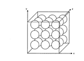
図3〜5は、第1の実施形態における渦補正パラメータを説明するための図である。第1の実施形態に係るMRI装置100は、撮像の位置毎の渦補正パラメータを予め準備する。例えば、図3に示すように、天板4a上に複数のファントムを配置し、この天板4aを傾斜磁場コイル2の空洞内に挿入し、代表的なパルスシーケンスによる実験的な撮像を行う。この実験的な撮像においては、様々な渦補正パラメータによる渦補正を試行し、収集したMR信号に及ぼされた影響を測定し、調整することで、適切な渦補正パラメータを決定する。
3 to 5 are diagrams for explaining vortex correction parameters in the first embodiment. The
例えば、図3に示すように、z軸方向に複数個のファントムを配置し、各ファントムを順次撮像し、様々な渦補正パラメータによる渦補正を試行することで、例えばファントムの位置毎に、短時定数の渦補正パラメータを決定する。例えば、『短時定数パラメータa』〜『短時定数パラメータe』を、短時定数の渦補正パラメータとして決定する。 For example, as shown in FIG. 3, a plurality of phantoms are arranged in the z-axis direction, each phantom is sequentially imaged, and vortex correction using various vortex correction parameters is attempted. Determine the time constant vortex correction parameters. For example, “short time constant parameter a” to “short time constant parameter e” are determined as the vortex correction parameters of the short time constant.
一方、第1の実施形態において、長時定数の渦補正パラメータは、全ての位置において共通のものが用いられる。例えば、磁場中心に合わせて準備された長時定数の渦補正パラメータが用いられる。このため、図3に示すように、撮像の位置毎の渦補正パラメータは、「『短時定数パラメータa』・『長時定数パラメータ(共通)』」のセット〜「『短時定数パラメータe』・『長時定数パラメータ(共通)』」のセットとなる。 On the other hand, in the first embodiment, the long time constant vortex correction parameter is common to all positions. For example, a vortex correction parameter having a long time constant prepared according to the center of the magnetic field is used. Therefore, as shown in FIG. 3, the vortex correction parameter for each imaging position is a set of "" short time constant parameter a "" "long time constant parameter (common)" to "" short time constant parameter e ". • “Long time constant parameter (common)” set.
なお、上記説明においては、z軸方向に複数個のファントムを配置し、短時定数の渦補正パラメータが、z軸方向の位置毎に決定されるものとして説明したが、実施形態はこれに限られるものではない。例えば、図4に示すように、x軸方向やy軸方向にも複数個のファントムを配置し、短時定数の渦補正パラメータを、z軸方向の位置毎のみならず、x軸方向やy軸方向の位置毎に決定してもよい。また、例えば、図5に示すように、短時定数の渦補正パラメータを、スライス単位で決定してもよい。さらに、短時定数の渦補正パラメータを、1スライスに含まれるライン単位で決定してもよい。すなわち、理論的には、少なくともMR信号の収集単位に応じて1つの渦補正パラメータを決定することが可能であるので、その任意の単位の位置毎に、渦補正パラメータを決定すればよい。 In the above description, a plurality of phantoms are arranged in the z-axis direction and the short time constant vortex correction parameter is determined for each position in the z-axis direction. However, the embodiment is not limited thereto. It is not something that can be done. For example, as shown in FIG. 4, a plurality of phantoms are also arranged in the x-axis direction and the y-axis direction, and the short time constant vortex correction parameter is set not only for each position in the z-axis direction but also in the x-axis direction and y-axis. You may determine for every position of an axial direction. For example, as shown in FIG. 5, the short time constant vortex correction parameter may be determined in units of slices. Further, the short time constant vortex correction parameter may be determined for each line included in one slice. That is, theoretically, since one vortex correction parameter can be determined according to at least an MR signal acquisition unit, the vortex correction parameter may be determined for each arbitrary unit position.
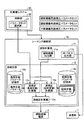
図6は、第1の実施形態に係るシーケンス制御部10の構成を示すブロック図である。RFパルス出力部11bは、計算機システム20からパルスシーケンス実行データを受信すると、このパルスシーケンス実行データに基づくRFパルスを出力するための制御信号を生成し、生成した制御信号を送信部7に送信する。
FIG. 6 is a block diagram illustrating a configuration of the
傾斜磁場出力部11aは、計算機システム20からパルスシーケンス実行データを受信すると、このパルスシーケンス実行データに基づく理想的な波形を出力するための制御信号(傾斜磁場の強度、タイミングなど)を生成し、生成した制御信号を、渦補正(長時定数)計算部12c及び渦補正(短時定数)計算部12dに、逐次送信する。
Upon receiving the pulse sequence execution data from the
長時定数パラメータ記憶部12aは、予め準備された長時定数パラメータを記憶する。第1の実施形態において、長時定数の渦補正パラメータは、全ての位置において共通のものが用いられる。一方、短時定数パラメータ記憶部12bは、撮像範囲の位置毎に予め準備された短時定数パラメータを記憶する。例えば、短時定数パラメータ記憶部12bは、『短時定数パラメータ1』〜『短時定数パラメータ5』を記憶する。
The long time constant parameter storage unit 12a stores a long time constant parameter prepared in advance. In the first embodiment, the long time constant vortex correction parameter is the same for all positions. On the other hand, the short time constant
渦補正(長時定数)計算部12cは、理想的な波形を出力するための制御信号を傾斜磁場出力部11aから受信すると、長時定数パラメータ記憶部12aから『長時定数パラメータ』を読み出し、読み出した『長時定数パラメータ』を用いて計算を行う。具体的には、渦補正(長時定数)計算部12cは、傾斜磁場の理想的な波形に対して『長時定数パラメータ』を用いた計算を行うことで、補正後の波形を出力するための制御信号を生成する。そして、渦補正(長時定数)計算部12cは、生成した制御信号、すなわち、補正後の波形を出力するための制御信号を、渦補正計算部12eに送信する。
When the control signal for outputting an ideal waveform is received from the gradient magnetic
なお、『長時定数パラメータ』には強度や時定数が含まれ、補正のための計算は、この強度や時定数を用いて行われる。また、この補正のための計算は、公知の技術を用いて実現される。 The “long time constant parameter” includes an intensity and a time constant, and a calculation for correction is performed using the intensity and the time constant. Further, the calculation for this correction is realized using a known technique.
一方、渦補正(短時定数)計算部12dは、理想的な波形を出力するための制御信号を傾斜磁場出力部11aから受信すると、短時定数パラメータ記憶部12bに記憶された複数の『短時定数パラメータ』から、撮像対象の位置に応じた『短時定数パラメータ』を選択し、選択した『短時定数パラメータ』を読み出す。例えば、渦補正(短時定数)計算部12dは、第1のTR(Time of Repetition)ならば『短時定数パラメータ1』を選択し、第5のTRならば『短時定数パラメータ5』を選択する。そして、渦補正(短時定数)計算部12dは、読み出した『短時定数パラメータ』を用いて計算を行う。具体的には、渦補正(短時定数)計算部12dは、傾斜磁場の理想的な波形に対して『短時定数パラメータ』を用いた計算を行うことで、補正後の波形を出力するための制御信号を生成する。そして、渦補正(短時定数)計算部12dは、生成した制御信号、すなわち、補正後の波形を出力するための制御信号を、渦補正計算部12eに送信する。
On the other hand, upon receiving a control signal for outputting an ideal waveform from the gradient magnetic
なお、『短時定数パラメータ』には強度や時定数が含まれ、補正のための計算は、この強度や時定数を用いて行われる。また、この補正のための計算は、公知の技術を用いて実現される。 The “short time constant parameter” includes an intensity and a time constant, and calculation for correction is performed using the intensity and the time constant. Further, the calculation for this correction is realized using a known technique.
渦補正計算部12eは、渦補正(長時定数)計算部12c及び渦補正(短時定数)計算部12dそれぞれから制御信号を受信すると、これらを合算し、補正後の波形を出力するための最終的な制御信号を生成する。そして、渦補正計算部12eは、生成した最終的な制御信号を、傾斜磁場電源3に送信する。すると、傾斜磁場電源3は、制御信号に基づき、補正後の波形に従う傾斜磁場を印加する。
Upon receiving control signals from the vortex correction (long time constant)
ここで、理想的な波形を出力するための制御信号は、傾斜磁場出力部11aから渦補正(長時定数)計算部12c及び渦補正(短時定数)計算部12dに逐次送信される。このため、渦補正(長時定数)計算部12c及び渦補正(短時定数)計算部12dは、『長時定数パラメータ』や『短時定数パラメータ』を用いた計算を逐次行い、補正後の波形を出力するための制御信号を、渦補正計算部12eに逐次送信することになる。そして、渦補正計算部12eも、最終的な制御信号を逐次生成し、傾斜磁場電源3に逐次送信する。言い換えると、傾斜磁場出力部11aから制御信号が出力され、傾斜磁場電源3が傾斜磁場を印加するまでの処理は、リアルタイムに行われる。
Here, a control signal for outputting an ideal waveform is sequentially transmitted from the gradient magnetic
なお、このようにリアルタイムに行われる理由を説明する。傾斜磁場の波形を出力するための制御信号は、通常撮像条件によって異なるため、検査を開始してから生成されることが多い。しかしながら、その量が膨大であるため、検査開始後、撮像開始前までに予め準備しておくことは、運用上あまり行われていない。検査を開始したにも係わらず、なかなか撮像が開始されないことになるからである。このような理由によるものなので、運用上の問題がなければ、特にリアルタイムに行われる必要はない。 The reason why such a process is performed in real time will be described. Since the control signal for outputting the waveform of the gradient magnetic field varies depending on the normal imaging conditions, it is often generated after the inspection is started. However, since the amount thereof is enormous, preparation in advance before the start of imaging after the start of inspection is not performed in practice. This is because although the inspection is started, imaging is not easily started. For this reason, if there is no operational problem, it does not need to be performed in real time.
さて、図3において、『長時定数のパラメータ』と、撮像の位置毎に準備された『短時定数のパラメータ』との位置単位のセットを、「渦補正パラメータのセット」と呼んだ。第1の実施形態においては、さらに、この位置単位の「渦補正パラメータのセット」を複数一括して管理している。例えば、図6に示すように、「頭部撮像用渦補正パラメータセット」、「腹部撮像用渦補正パラメータセット」、「下肢撮像用渦補正パラメータセット」などである。 In FIG. 3, a set of position units of “long time constant parameter” and “short time constant parameter” prepared for each imaging position is called “vortex correction parameter set”. In the first embodiment, a plurality of “vortex correction parameter sets” in units of positions are managed collectively. For example, as shown in FIG. 6, “head imaging vortex correction parameter set”, “abdominal imaging vortex correction parameter set”, “lower limb imaging vortex correction parameter set”, and the like.
制御部26が有するパラメータ選択部27は、操作者から入力された撮像条件に基づいて、撮像条件に応じて予め分類された渦補正パラメータのセットを選択する。例えば、パラメータ選択部27は、撮像条件から、実行されようとしている撮像が「頭部撮像」であることを判定し、「頭部撮像用渦補正パラメータセット」を選択する。そして、パラメータ選択部27は、「頭部撮像用渦補正パラメータセット」を用いるように通知する制御信号を、渦補正(長時定数)計算部12c及び渦補正(短時定数)計算部12dに送信する。渦補正(長時定数)計算部12c及び渦補正(短時定数)計算部12dは、この制御信号を受信すると、「頭部撮像用渦補正パラメータセット」を選択し、渦補正の計算に、この「頭部撮像用渦補正パラメータセット」に含まれる渦補正パラメータを用いる。なお、渦補正パラメータセットの分類は、これに限られるものではなく、例えば、パルスシーケンスの種類によって分類されていてもよい。また、渦補正パラメータセットの選択は、直接操作者から受け付けてもよい。
The
図7は、第1の実施形態におけるパルスシーケンスへの適用を説明するための図である。図7においては、1シーケンスに例えば5TRが含まれる。1TRにおいて、1スライスが撮像されるか、あるいは、1ラインが撮像されるかは、パルスシーケンスの種類によって異なる。いずれの場合も、TR毎に撮像の位置が変わるとすれば、仮にTRの単位と同じ単位で『短時定数パラメータ』が準備されているのであれば、図7に示すように、TR毎に異なる『短時定数パラメータ』が適用される。 FIG. 7 is a diagram for explaining application to the pulse sequence in the first embodiment. In FIG. 7, for example, 5TR is included in one sequence. Whether one slice is imaged or one line is imaged in 1TR differs depending on the type of pulse sequence. In any case, if the imaging position changes for each TR, if the “short time constant parameter” is prepared in the same unit as the TR unit, as shown in FIG. Different “short time constant parameters” apply.
例えば、『短時定数パラメータ』がスライス単位で準備されており、一方、1TRにおいて1スライスが撮像されるパルスシーケンスであるとする。この場合、渦補正(短時定数)計算部12dは、TR毎に、そのスライス位置に応じた『短時定数パラメータ』を選択すればよい。また、一度選択した『短時定数パラメータ』を、1シーケンス内で再び選択してもよい。なお、1TRと1TRとの間には若干の空き時間があるので、あるTRにおいて行われた『短時定数パラメータ』による補正の影響が、次のTRにおける傾斜磁場に及ぶことはないと考えられる。すなわち、TR毎に異なる『短時定数パラメータ』を適用してもよい。
For example, it is assumed that a “short time constant parameter” is prepared in units of slices, while a pulse sequence in which one slice is imaged in 1TR. In this case, the vortex correction (short time constant)
上述したように、第1の実施形態によれば、短時定数の渦補正パラメータを撮像の位置毎に準備し、傾斜磁場の波形を位置に応じて補正するので、渦補正を適切に行うことができる。例えば、磁場中心から外れた位置の撮像においても渦補正を適切に行うことができるので、画像の劣化を抑え、安定した画像を得ることが可能になる。 As described above, according to the first embodiment, the short time constant vortex correction parameter is prepared for each imaging position, and the gradient magnetic field waveform is corrected according to the position. Can do. For example, eddy correction can be appropriately performed even in imaging at a position deviating from the magnetic field center, so that it is possible to suppress image deterioration and obtain a stable image.
(第2の実施形態)
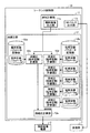
第2の実施形態に係るMRI装置100は、以下に特記する事項を除き、第1の実施形態と同様の構成を有する。図8は、第2の実施形態に係るシーケンス制御部10の構成を示すブロック図である。
(Second Embodiment)
The
図8に示すように、第2の実施形態に係るシーケンス制御部10は、渦補正部12に、『短時定数パラメータ』毎の複数の渦補正(短時定数)計算部12dを有する。そして、各渦補正(短時定数)計算部12dが、対応する『短時定数パラメータ』を用いた計算を個別に行う。
As illustrated in FIG. 8, the
第1の実施形態において、渦補正(短時定数)計算部12dによる計算は、理想的な波形を出力するための制御信号を傾斜磁場出力部11aから受信し、『短時定数パラメータ』を選択した後に開始される。この場合、理想的な波形を出力するための制御信号を受信してから補正後の制御信号が生成されるまでの時間が長くなる。
In the first embodiment, calculation by the eddy correction (short time constant)
これに対し、第2の実施形態において、渦補正(短時定数)計算部12dは、対応する『短時定数パラメータ』を用いた計算を常時行い、計算結果を常時出力している。例えば、図7に示すように、1シーケンスに5TRが含まれる場合、各TRにおいて理想的な傾斜磁場の波形は同一であるとする。一方で、TR毎に撮像位置は異なるので、渦補正に用いるべき『短時定数パラメータ』は異なる。
On the other hand, in the second embodiment, the vortex correction (short time constant)
ここで、第1の1TRが実行された段階で、各渦補正(短時定数)計算部12dは、1TR分の理想的な傾斜磁場の波形を把握することができる。そこで、例えば、『短時定数パラメータ2』に対応する渦補正(短時定数)計算部12dは、第1の1TRが実行されている最中に、予め、『短時定数パラメータ2』を用いた計算を行い、制御信号を生成しておく。同様に、例えば、『短時定数パラメータ3』に対応する渦補正(短時定数)計算部12dも、第1の1TRが実行されている最中に、予め、『短時定数パラメータ3』を用いた計算を行い、制御信号を生成しておく。なお、渦補正(長時定数)計算部12dも、少なくとも第2の1TR以降は、第1の1TRにおいて既に計算した計算結果を保持することができる。
Here, at the stage where the first 1TR is executed, each eddy correction (short time constant)
このように併行して計算を行うことで、理想的な波形を出力するための制御信号を受信してから補正後の制御信号が生成されるまでの時間は大幅に短縮され、渦補正部12による処理時間が短縮されることになる。仮に、1TRと1TRとの間の空き時間が短い場合にも、適用することが可能である。
By performing the calculation in parallel, the time from reception of a control signal for outputting an ideal waveform to generation of a corrected control signal is greatly reduced, and the
なお、第2の実施形態においては、渦補正部12が、『短時定数パラメータ』の数と同数の渦補正(短時定数)計算部12dを有するものとして説明した。しかしながら、実施形態はこれに限られるものではない。必ずしも『短時定数パラメータ』の数と同数の渦補正(短時定数)計算部12dを有しない場合であっても、例えば2つの渦補正(短時定数)計算部12dが、互いに先行して次のTRのための計算を行い、事前に計算結果を保持してもよい。
In the second embodiment, the
上述したように、第2の実施形態によれば、渦補正部12に『短時定数パラメータ』毎の複数の渦補正(短時定数)計算部12dを有し、各渦補正(短時定数)計算部12dが、対応する『短時定数パラメータ』を用いた計算を個別に行うので、処理時間を大幅に短縮することができる。
As described above, according to the second embodiment, the
(第3の実施形態)
第3の実施形態に係るMRI装置100は、以下に特記する事項を除き、第1の実施形態と同様の構成を有する。図9は、第3の実施形態に係るシーケンス制御部10の構成を示すブロック図である。
(Third embodiment)
The
図9に示すように、第3の実施形態に係るシーケンス制御部10は、長時定数パラメータ記憶部12aに、撮像の位置毎の『長時定数パラメータ』を記憶する。すなわち、第1及び第2の実施形態において、長時定数の渦補正パラメータは、全ての位置において共通のものが用いられた。第3の実施形態において、長時定数の渦補正パラメータは、撮像の位置毎に異なるものを用いる。
As shown in FIG. 9, the
上述したように、一般に、長時定数の渦磁場は、撮像範囲の全ての位置においてほぼ同様の影響を及ぼすと考えられている。しかしながら、必ずしも完全に同一の影響であるとは言い切れず、位置毎に異なる『長時定数パラメータ』を用いることで、渦補正の精度をより高めることが期待できる。 As described above, it is generally considered that a long time constant eddy magnetic field has almost the same effect at all positions in the imaging range. However, it cannot be said that the influences are completely the same, and it can be expected that the accuracy of vortex correction is further improved by using a “long time constant parameter” that is different for each position.
このようなことから、第3の実施形態に係るシーケンス制御部10は、渦補正部12に、『長時定数パラメータ』毎の複数の渦補正計算部12fを有する。なお、第3の実施形態においては、図9に示すように、『短時定数パラメータ』を用いた計算と『長時定数パラメータ』を用いた計算とを1つの渦補正計算部12fが行うことを想定する。各渦補正(長・短時定数)計算部12fは、同じ位置に対応する『短時定数パラメータ』を用いた計算と『長時定数パラメータ』を用いた計算とを行う。しかしながら、実施形態はこれに限られるものではなく、渦補正部12は、『短時定数パラメータ』用の複数の渦補正計算部12fと、『長時定数パラメータ』用の複数の渦補正計算部12fとを別々に有してもよい。
For this reason, the
上述したように、第3の実施形態によれば、さらに長時定数の渦補正パラメータを撮像の位置毎に準備し、傾斜磁場の波形を位置に応じて補正するので、渦補正をより精度良く行うことができる。 As described above, according to the third embodiment, the vortex correction parameter having a longer time constant is prepared for each imaging position, and the waveform of the gradient magnetic field is corrected according to the position. It can be carried out.
本発明のいくつかの実施形態を説明したが、これらの実施形態は、例として提示したものであり、発明の範囲を限定することは意図していない。これら実施形態は、その他の様々な形態で実施されることが可能であり、発明の要旨を逸脱しない範囲で、種々の省略、置き換え、変更を行うことができる。これら実施形態やその変形は、発明の範囲や要旨に含まれると同様に、特許請求の範囲に記載された発明とその均等の範囲に含まれるものである。 Although several embodiments of the present invention have been described, these embodiments are presented by way of example and are not intended to limit the scope of the invention. These embodiments can be implemented in various other forms, and various omissions, replacements, and changes can be made without departing from the spirit of the invention. These embodiments and their modifications are included in the scope and gist of the invention, and are also included in the invention described in the claims and the equivalents thereof.
11 波形計算部
11a 傾斜磁場出力部
11b RFパルス出力部
12 渦補正部
12a 長時定数パラメータ記憶部
12b 短時定数パラメータ記憶部
12c 渦補正(長時定数)計算部
12d 渦補正(短時定数)計算部
12e 渦補正計算部
DESCRIPTION OF
Claims (5)
撮像条件に従って計算された傾斜磁場の波形を受け付け、受け付けた傾斜磁場の波形に対し、前記位置に応じて選択された渦補正パラメータによる計算を行い、計算結果として得られた補正後の波形を、傾斜磁場電源に対して出力する渦補正部と、
前記補正後の波形を受け付け、前記補正後の波形に従って傾斜磁場を印加する傾斜磁場電源と
を備えたことを特徴とする磁気共鳴イメージング装置。 A storage unit that stores vortex correction parameters for correcting the influence of the eddy magnetic field for each imaging position;
Accept the gradient magnetic field waveform calculated according to the imaging conditions, perform the calculation with the eddy correction parameter selected according to the position for the received gradient magnetic field waveform, the corrected waveform obtained as a calculation result, A vortex correction unit that outputs to the gradient magnetic field power supply;
A magnetic resonance imaging apparatus, comprising: a gradient magnetic field power source that receives the corrected waveform and applies a gradient magnetic field according to the corrected waveform.
各渦補正部が、対応する渦補正パラメータを用いた計算を個別に行うことを特徴とする請求項1〜3のいずれか一つに記載の磁気共鳴イメージング装置。 A plurality of the vortex correction units are provided for each vortex correction parameter,
The magnetic resonance imaging apparatus according to claim 1, wherein each vortex correction unit individually performs calculation using a corresponding vortex correction parameter.
前記渦補正部は、選択された前記渦補正パラメータのセットの中から、撮像の位置に応じた渦補正パラメータを選択して前記計算を行うことを特徴とする請求項1〜4のいずれか一つに記載の磁気共鳴イメージング装置。 A selection unit for selecting a set of vortex correction parameters classified in advance according to the imaging condition based on the imaging condition;
5. The vortex correction unit performs the calculation by selecting a vortex correction parameter corresponding to an imaging position from the selected set of vortex correction parameters. The magnetic resonance imaging apparatus described in 1.
Priority Applications (3)
| Application Number | Priority Date | Filing Date | Title |
|---|---|---|---|
| JP2011049310A JP2012183233A (en) | 2011-03-07 | 2011-03-07 | Magnetic resonance imaging apparatus |
| CN201210055807.6A CN102764122B (en) | 2011-03-07 | 2012-03-05 | Magnetic resonance imaging apparatus |
| US13/412,665 US9157973B2 (en) | 2011-03-07 | 2012-03-06 | Magnetic resonance imaging apparatus |
Applications Claiming Priority (1)
| Application Number | Priority Date | Filing Date | Title |
|---|---|---|---|
| JP2011049310A JP2012183233A (en) | 2011-03-07 | 2011-03-07 | Magnetic resonance imaging apparatus |
Publications (1)
| Publication Number | Publication Date |
|---|---|
| JP2012183233A true JP2012183233A (en) | 2012-09-27 |
Family
ID=46794952
Family Applications (1)
| Application Number | Title | Priority Date | Filing Date |
|---|---|---|---|
| JP2011049310A Pending JP2012183233A (en) | 2011-03-07 | 2011-03-07 | Magnetic resonance imaging apparatus |
Country Status (3)
| Country | Link |
|---|---|
| US (1) | US9157973B2 (en) |
| JP (1) | JP2012183233A (en) |
| CN (1) | CN102764122B (en) |
Cited By (3)
| Publication number | Priority date | Publication date | Assignee | Title |
|---|---|---|---|---|
| JP2019502485A (en) * | 2016-01-22 | 2019-01-31 | コーニンクレッカ フィリップス エヌ ヴェKoninklijke Philips N.V. | Subsequent MRI configuration dependent eddy current compensation |
| JP2019097747A (en) * | 2017-11-30 | 2019-06-24 | キヤノンメディカルシステムズ株式会社 | Magnetic resonance imaging apparatus |
| JP2019213852A (en) * | 2018-06-12 | 2019-12-19 | コーニンクレッカ フィリップス エヌ ヴェKoninklijke Philips N.V. | Determination of higher order terms of three-dimensional gradient impulse response function |
Families Citing this family (3)
| Publication number | Priority date | Publication date | Assignee | Title |
|---|---|---|---|---|
| KR101473872B1 (en) * | 2013-02-05 | 2014-12-18 | 삼성전자 주식회사 | Magnetic resonance imaging device and control method thereof |
| KR102598740B1 (en) * | 2015-05-12 | 2023-11-03 | 티에이이 테크놀로지스, 인크. | Systems and methods for reducing unwanted eddy currents |
| CN106483482B (en) * | 2015-08-25 | 2019-08-23 | 上海联影医疗科技有限公司 | Gradient eddy bearing calibration and device for magnetic resonance imaging system |
Citations (15)
| Publication number | Priority date | Publication date | Assignee | Title |
|---|---|---|---|---|
| US4585995A (en) * | 1984-04-19 | 1986-04-29 | Technicare Corporation | Nuclear magnetic resonance eddy field suppression apparatus |
| JPS6227932A (en) * | 1985-07-25 | 1987-02-05 | ピカ− インタ−ナシヨナル インコ−ポレイテツド | Method and apparatus for generating gradient magnetic field for nuclear magnetic imaging |
| JPH0422338A (en) * | 1990-05-16 | 1992-01-27 | Yokogawa Medical Syst Ltd | Mr device |
| JPH05269101A (en) * | 1991-09-19 | 1993-10-19 | Toshiba Corp | Nuclear magnetic resonance imaging device |
| JPH0638942A (en) * | 1992-03-13 | 1994-02-15 | Toshiba Corp | Gradient coil of magnetic resonance video apparatus and manufacture thereof |
| JPH0654820A (en) * | 1991-09-30 | 1994-03-01 | Toshiba Corp | Magnetic resonance diagnostic device |
| JPH06181905A (en) * | 1992-08-04 | 1994-07-05 | Univ California | Mri gradient magnetic field drive electric current control using all digital controller |
| US5451877A (en) * | 1993-04-23 | 1995-09-19 | Siemens Aktiengesellschaft | Method for the compensation of eddy currents caused by gradients in a nuclear magnetic resonance apparatus |
| US6066949A (en) * | 1997-11-19 | 2000-05-23 | The Board Of Trustees Of The Leland Stanford Junior University | Gradient characterization using fourier-transform |
| JP2000262485A (en) * | 1999-03-12 | 2000-09-26 | Toshiba Corp | Eddy magnetic field measuring method, and magnetic resonance imaging device |
| JP2001112739A (en) * | 1999-10-01 | 2001-04-24 | Siemens Ag | Method for setting desired amount of gradient magnetic field |
| JP2001258865A (en) * | 2000-02-24 | 2001-09-25 | Toshiba America Mri Inc | Method and system for measuring and compensating eddy current induced during nmr imaging operation |
| JP2005288026A (en) * | 2004-04-05 | 2005-10-20 | Toshiba Corp | Magnetic resonance imaging device, eddy magnetic field distribution estimating method and static magnetic field correction method |
| JP2009172360A (en) * | 2007-12-28 | 2009-08-06 | Toshiba Corp | Magnetic resonance imaging device and control program of magnetic resonance imaging device |
| WO2010143586A1 (en) * | 2009-06-10 | 2010-12-16 | 株式会社 日立メディコ | Magnetic resonance imaging device and eddy current compensation method |
Family Cites Families (9)
| Publication number | Priority date | Publication date | Assignee | Title |
|---|---|---|---|---|
| GB8719396D0 (en) * | 1987-08-17 | 1987-09-23 | Picker Int Ltd | Eddy current compensation |
| JP3112930B2 (en) | 1990-09-28 | 2000-11-27 | 株式会社東芝 | Magnetic resonance equipment |
| US5770943A (en) | 1996-12-30 | 1998-06-23 | General Electric Company | Method for measuring and compensating for spatially and temporally varying magnetic fields induced by eddy currents |
| JP3930439B2 (en) * | 2003-02-06 | 2007-06-13 | ジーイー・メディカル・システムズ・グローバル・テクノロジー・カンパニー・エルエルシー | Eddy current correction method and magnetic resonance imaging apparatus |
| JP4343726B2 (en) | 2003-02-12 | 2009-10-14 | 株式会社日立メディコ | Magnetic resonance imaging apparatus and irregular magnetic field correction method |
| US7112964B2 (en) * | 2004-08-02 | 2006-09-26 | General Electric Company | Eddy current measurement and correction in magnetic resonance imaging systems with a static phantom |
| US8008915B2 (en) * | 2007-12-28 | 2011-08-30 | Kabushiki Kaisha Toshiba | Magnetic resonance imaging apparatus and magnetic resonance imaging method |
| JP5416960B2 (en) * | 2008-12-17 | 2014-02-12 | 株式会社東芝 | Magnetic resonance imaging system |
| JP2012040362A (en) * | 2010-07-23 | 2012-03-01 | Toshiba Corp | Magnetic resonance imaging method, magnetic resonance imaging apparatus, and control device of magnetic resonance imaging apparatus |
-
2011
- 2011-03-07 JP JP2011049310A patent/JP2012183233A/en active Pending
-
2012
- 2012-03-05 CN CN201210055807.6A patent/CN102764122B/en active Active
- 2012-03-06 US US13/412,665 patent/US9157973B2/en active Active
Patent Citations (15)
| Publication number | Priority date | Publication date | Assignee | Title |
|---|---|---|---|---|
| US4585995A (en) * | 1984-04-19 | 1986-04-29 | Technicare Corporation | Nuclear magnetic resonance eddy field suppression apparatus |
| JPS6227932A (en) * | 1985-07-25 | 1987-02-05 | ピカ− インタ−ナシヨナル インコ−ポレイテツド | Method and apparatus for generating gradient magnetic field for nuclear magnetic imaging |
| JPH0422338A (en) * | 1990-05-16 | 1992-01-27 | Yokogawa Medical Syst Ltd | Mr device |
| JPH05269101A (en) * | 1991-09-19 | 1993-10-19 | Toshiba Corp | Nuclear magnetic resonance imaging device |
| JPH0654820A (en) * | 1991-09-30 | 1994-03-01 | Toshiba Corp | Magnetic resonance diagnostic device |
| JPH0638942A (en) * | 1992-03-13 | 1994-02-15 | Toshiba Corp | Gradient coil of magnetic resonance video apparatus and manufacture thereof |
| JPH06181905A (en) * | 1992-08-04 | 1994-07-05 | Univ California | Mri gradient magnetic field drive electric current control using all digital controller |
| US5451877A (en) * | 1993-04-23 | 1995-09-19 | Siemens Aktiengesellschaft | Method for the compensation of eddy currents caused by gradients in a nuclear magnetic resonance apparatus |
| US6066949A (en) * | 1997-11-19 | 2000-05-23 | The Board Of Trustees Of The Leland Stanford Junior University | Gradient characterization using fourier-transform |
| JP2000262485A (en) * | 1999-03-12 | 2000-09-26 | Toshiba Corp | Eddy magnetic field measuring method, and magnetic resonance imaging device |
| JP2001112739A (en) * | 1999-10-01 | 2001-04-24 | Siemens Ag | Method for setting desired amount of gradient magnetic field |
| JP2001258865A (en) * | 2000-02-24 | 2001-09-25 | Toshiba America Mri Inc | Method and system for measuring and compensating eddy current induced during nmr imaging operation |
| JP2005288026A (en) * | 2004-04-05 | 2005-10-20 | Toshiba Corp | Magnetic resonance imaging device, eddy magnetic field distribution estimating method and static magnetic field correction method |
| JP2009172360A (en) * | 2007-12-28 | 2009-08-06 | Toshiba Corp | Magnetic resonance imaging device and control program of magnetic resonance imaging device |
| WO2010143586A1 (en) * | 2009-06-10 | 2010-12-16 | 株式会社 日立メディコ | Magnetic resonance imaging device and eddy current compensation method |
Cited By (5)
| Publication number | Priority date | Publication date | Assignee | Title |
|---|---|---|---|---|
| JP2019502485A (en) * | 2016-01-22 | 2019-01-31 | コーニンクレッカ フィリップス エヌ ヴェKoninklijke Philips N.V. | Subsequent MRI configuration dependent eddy current compensation |
| JP7021089B2 (en) | 2016-01-22 | 2022-02-16 | コーニンクレッカ フィリップス エヌ ヴェ | Subsequent MRI configuration-dependent eddy current compensation |
| JP2019097747A (en) * | 2017-11-30 | 2019-06-24 | キヤノンメディカルシステムズ株式会社 | Magnetic resonance imaging apparatus |
| JP7152146B2 (en) | 2017-11-30 | 2022-10-12 | キヤノンメディカルシステムズ株式会社 | Magnetic resonance imaging device |
| JP2019213852A (en) * | 2018-06-12 | 2019-12-19 | コーニンクレッカ フィリップス エヌ ヴェKoninklijke Philips N.V. | Determination of higher order terms of three-dimensional gradient impulse response function |
Also Published As
| Publication number | Publication date |
|---|---|
| US9157973B2 (en) | 2015-10-13 |
| CN102764122A (en) | 2012-11-07 |
| US20120229139A1 (en) | 2012-09-13 |
| CN102764122B (en) | 2015-05-20 |
Similar Documents
| Publication | Publication Date | Title |
|---|---|---|
| KR101663365B1 (en) | Determination of a magnetic resonance control sequence | |
| JP2012183233A (en) | Magnetic resonance imaging apparatus | |
| JP6072825B2 (en) | Use of gradient coils to correct higher order BO field inhomogeneities in MR imaging | |
| JP2012213618A (en) | Gradient amplifier system | |
| JP2012192185A5 (en) | ||
| US10551466B2 (en) | Correction of a magnetic resonance transmission signal | |
| JP2018167025A (en) | Magnetic resonance imaging apparatus and medical processor | |
| KR101310706B1 (en) | Magnet resonance imaging device for constructing grey matter mr image selectively and method using the same | |
| JP2017537763A5 (en) | ||
| US10067209B2 (en) | Magnetic resonance imaging apparatus | |
| JP6651330B2 (en) | Magnetic resonance imaging equipment | |
| US10156622B2 (en) | Method and apparatus for sectional optimization of radial MR pulse sequences | |
| US10353042B2 (en) | MRI apparatus | |
| JP2020043898A (en) | High-frequency amplification apparatus and magnetic resonance imaging apparatus | |
| US9770187B2 (en) | Magnetic resonance imaging apparatus | |
| US11035921B2 (en) | Method and system for operating a magnetic resonance facility | |
| JP7267752B2 (en) | Magnetic resonance imaging apparatus and k-space trajectory correction method | |
| JP6181374B2 (en) | Magnetic resonance imaging system | |
| JP2011182916A (en) | Magnetic resonance imaging apparatus | |
| US10996294B2 (en) | MRI apparatus and RF amplification circuit | |
| JP6245891B2 (en) | Magnetic resonance imaging system | |
| JP7201360B2 (en) | Magnetic resonance imaging device | |
| JP2015198737A (en) | Magnetic resonance imaging device and gradient magnetic field power supply | |
| JP7000119B2 (en) | Magnetic resonance imaging device and pulse design method | |
| JP5925486B2 (en) | Magnetic resonance imaging system |
Legal Events
| Date | Code | Title | Description |
|---|---|---|---|
| A621 | Written request for application examination |
Free format text: JAPANESE INTERMEDIATE CODE: A621 Effective date: 20140217 |
|
| A977 | Report on retrieval |
Free format text: JAPANESE INTERMEDIATE CODE: A971007 Effective date: 20140630 |
|
| A131 | Notification of reasons for refusal |
Free format text: JAPANESE INTERMEDIATE CODE: A131 Effective date: 20140729 |
|
| A521 | Written amendment |
Free format text: JAPANESE INTERMEDIATE CODE: A523 Effective date: 20140929 |
|
| A131 | Notification of reasons for refusal |
Free format text: JAPANESE INTERMEDIATE CODE: A131 Effective date: 20150210 |
|
| A02 | Decision of refusal |
Free format text: JAPANESE INTERMEDIATE CODE: A02 Effective date: 20150804 |