JP2012183139A - Measuring device - Google Patents
Measuring device Download PDFInfo
- Publication number
- JP2012183139A JP2012183139A JP2011047269A JP2011047269A JP2012183139A JP 2012183139 A JP2012183139 A JP 2012183139A JP 2011047269 A JP2011047269 A JP 2011047269A JP 2011047269 A JP2011047269 A JP 2011047269A JP 2012183139 A JP2012183139 A JP 2012183139A
- Authority
- JP
- Japan
- Prior art keywords
- value
- amplitude value
- unit
- gain
- sensitivity
- Prior art date
- Legal status (The legal status is an assumption and is not a legal conclusion. Google has not performed a legal analysis and makes no representation as to the accuracy of the status listed.)
- Granted
Links
Images


Abstract
Description
本発明は、計測装置等に関する。 The present invention relates to a measuring device and the like.
計測対象の変位を検出する計測装置は、例えば、特許文献1に記載されている。特許文献1に記載の計測装置は、検出された信号を増幅する増幅器のゲインを、増幅された信号の大きさに応じて設定し直すゲイン設定部を有している。
A measurement device that detects the displacement of a measurement target is described in
また、拍動検出装置は、人体の心拍に由来する拍動を検出するための装置であって、例えば、腕、手のひら、手指などに装着される脈波センサー部からの信号(脈波信号)から、人体の体動の影響により発生する信号成分(体動影響信号)を雑音として除去し、心拍に由来する信号(拍動信号)を検出する装置である。人の指や手首に装着するタイプの脈拍計は、例えば、特許文献2〜特許文献4に記載されている。
The pulsation detection device is a device for detecting a pulsation derived from a heartbeat of a human body. For example, a signal (pulse wave signal) from a pulse wave sensor unit attached to an arm, a palm, a finger, or the like. Thus, a signal component (body motion influence signal) generated due to the influence of body motion of a human body is removed as noise, and a signal derived from a heartbeat (beat signal) is detected. For example,
計測装置が動作を開始すると、増幅器のゲインを、計測対象の状態に対応する適切なゲインに設定する必要がある。ゲイン設定は、正確に行われるのが好ましく、また、迅速に行われるのが好ましい。 When the measurement apparatus starts operation, it is necessary to set the gain of the amplifier to an appropriate gain corresponding to the state of the measurement target. The gain setting is preferably performed accurately, and is preferably performed quickly.
本発明の少なくとも一つの態様によれば、例えば、増幅器のゲイン設定の精度を高めることができる。また、例えば、増幅器のゲイン設定を迅速に行うことができる。 According to at least one aspect of the present invention, for example, the gain setting accuracy of the amplifier can be increased. Also, for example, the gain setting of the amplifier can be performed quickly.
(1)本発明の計測装置の一態様は、計測対象の情報を含む信号を出力するセンサー素子と、前記計測対象の情報を含む信号を増幅する増幅器と、を含むセンサー部と、前記センサー部から出力されるセンサー信号の、所定期間における最大値と最小値との差分を振幅値として検出し、前記振幅値が所定の許容振幅値に占める割合の程度に基づいて、前記センサー部の感度を調整する感度調整部と、を有する。 (1) One aspect of the measurement apparatus according to the present invention is a sensor unit including a sensor element that outputs a signal including information on a measurement target, an amplifier that amplifies the signal including information on the measurement target, and the sensor unit. The difference between the maximum value and the minimum value of the sensor signal output from the predetermined period is detected as an amplitude value, and the sensitivity of the sensor unit is determined based on the degree of the ratio of the amplitude value to the predetermined allowable amplitude value. A sensitivity adjustment unit for adjustment.
本態様では、「センサー信号の振幅値が所定の許容振幅値に占める割合の程度」に基づいて、センサー部の感度が調整(制御)される。所定期間におけるセンサー信号の振幅値は、所定期間における最大値と最小値との差分によって定まる。 In this aspect, the sensitivity of the sensor unit is adjusted (controlled) based on “the degree of the ratio of the amplitude value of the sensor signal to the predetermined allowable amplitude value”. The amplitude value of the sensor signal in the predetermined period is determined by the difference between the maximum value and the minimum value in the predetermined period.
本態様では、センサー信号の振幅が、許容振幅値(ダイナミックレンジ)に対してどのような割合になっているかを検出する。したがって、例えば、センサー信号の振幅が、許容振幅値(ダイナミックレンジ)内で、可能な限り大きくなるように(例えば、最大となるように)、センサー部の感度を設定することができる。したがって、センサー部の感度を、計測対象の状態に対応する適切な感度(例えば可能な限り大きな感度)に設定することができる。 In this aspect, the ratio of the amplitude of the sensor signal to the allowable amplitude value (dynamic range) is detected. Therefore, for example, the sensitivity of the sensor unit can be set so that the amplitude of the sensor signal is as large as possible (for example, maximized) within the allowable amplitude value (dynamic range). Therefore, the sensitivity of the sensor unit can be set to an appropriate sensitivity (for example, as large as possible) corresponding to the state of the measurement target.
(2)本発明の計測装置の他の態様では、前記計測装置が計測を開始した計測開始時点から第1時間が経過した時点を第1時点とし、前記第1時点から第2時間が経過した時点を第2時点とし、前記計測開始時点から前記第2時点までを第1期間としたとき、前記感度調整部は、前記第1期間においては、前記センサー部の感度を所定の設定感度とし、前記所定期間は、前記第1時点から前記第2時点までの期間とし、かつ、前記第2時点において、検出された前記振幅値が前記所定の許容振幅値に占める割合の程度に基づいて、前記センサー部の感度を調整する。 (2) In another aspect of the measuring device of the present invention, the first time is the time when the first time has elapsed from the measurement start time when the measuring device started the measurement, and the second time has elapsed from the first time. When the time point is the second time point and the measurement start time point to the second time point is the first period, the sensitivity adjustment unit sets the sensitivity of the sensor unit to a predetermined setting sensitivity in the first period, The predetermined period is a period from the first time point to the second time point, and at the second time point, based on the degree of the ratio of the detected amplitude value to the predetermined allowable amplitude value, Adjust the sensitivity of the sensor section.
本態様では、計測開始時点から第1時間が経過した時点を第1時点とし、前記第1時点から第2時間が経過した時点を第2時点とし、計測開始時点から第2時点までを第1期間とする。ここで、第1時間をT1とし、第2時間をT2とし、第1期間をTXとする。 In this aspect, the time point at which the first time has elapsed from the measurement start time point is defined as the first time point, the time point at which the second time has elapsed from the first time point is defined as the second time point, and the time from the measurement start time point to the second time point is defined as the first time point. Period. Here, the first time is T1, the second time is T2, and the first period is TX.
本態様では、増幅器のゲインが、所定の初期設定感度に設定されている状態で、計測が開始される。計測が開始された後、第1期間(TX)が経過した第2時点で、第1時点から第2時点までの期間(上記(1)の態様における所定期間に相当する)において検出された、「センサー信号の振幅値が所定の許容振幅値に占める割合の程度」に基づいて、増幅器のゲインの設定(ゲインの見直し)が実行される。すなわち、計測開始後、第1期間(TX)が経過した時点で、増幅器のゲインは、計測対象の状態に応じた適切な値になる。第1期間(TX)の長さを適切に設定すれば、計測開始後、早期に増幅器のゲインの最適化が可能である。すなわち、増幅器の初期ゲイン設定を、正確かつ迅速に行うことができる。 In this aspect, measurement is started in a state where the gain of the amplifier is set to a predetermined initial sensitivity. Detected in a period from the first time point to the second time point (corresponding to the predetermined period in the above aspect (1)) at the second time point when the first period (TX) has elapsed after the measurement was started. Based on “the degree of the ratio of the amplitude value of the sensor signal to the predetermined allowable amplitude value”, the setting of the gain of the amplifier (review of the gain) is executed. That is, when the first period (TX) has elapsed after the start of measurement, the gain of the amplifier becomes an appropriate value according to the state of the measurement target. If the length of the first period (TX) is set appropriately, the gain of the amplifier can be optimized early after the start of measurement. That is, the initial gain setting of the amplifier can be performed accurately and quickly.
また、計測開始当初の期間では、例えば回路動作の開始等に伴うノイズが生じ易い。本態様では、計測開始時点から第1時点までの第1時間を適切な長さに設定すること、すなわち、第1時間内で、ノイズが生じ易い時期が終了するようにすることによって、「センサー信号の振幅値が所定の許容振幅値に占める割合の程度」の検出の精度を高めることができる。 In the initial period of measurement, for example, noise accompanying the start of circuit operation is likely to occur. In this aspect, by setting the first time from the measurement start time to the first time to an appropriate length, that is, by causing the period when noise is likely to occur within the first time to end, the “sensor The accuracy of detection of “the degree of the ratio of the amplitude value of the signal to the predetermined allowable amplitude value” can be increased.
(3)本発明の計測装置の他の態様では、前記感度調整部は、前記所定期間において、前記センサー信号の振幅値が前記所定の許容振幅値を超えるか否かを検出し、前記所定の許容振幅値を超えるか否かの検出結果に基づいて、前記センサー部の感度を調整する。 (3) In another aspect of the measuring apparatus of the present invention, the sensitivity adjustment unit detects whether the amplitude value of the sensor signal exceeds the predetermined allowable amplitude value during the predetermined period, and The sensitivity of the sensor unit is adjusted based on the detection result of whether or not the allowable amplitude value is exceeded.
本態様は、感度調整部は、センサー信号の振幅値が、所定の許容振幅値(ダイナミックレンジ)を超えるか否かを検出し、検出結果に基づいてセンサー部の感度調整を実行する。なお、センサー信号の振幅値が所定の許容振幅値(ダイナミックレンジ)を超える現象を「振り切れ」といってもよい。振り切れが生じたときには、増幅器から出力されるセンサー信号の値は、飽和した状態となっている。 In this aspect, the sensitivity adjustment unit detects whether the amplitude value of the sensor signal exceeds a predetermined allowable amplitude value (dynamic range), and performs sensitivity adjustment of the sensor unit based on the detection result. A phenomenon in which the amplitude value of the sensor signal exceeds a predetermined allowable amplitude value (dynamic range) may be referred to as “shake-out”. When the shakeout occurs, the value of the sensor signal output from the amplifier is saturated.
振り切れが生じていることは、所定の振幅許容値(ダイナミックレンジ)を超える過大な信号が増幅器に入力されていることを意味する。この場合、感度調整部が、センサー部の感度を減少させることによって、振り切れが生じないようにすることができる。 The occurrence of shaking out means that an excessive signal exceeding a predetermined amplitude allowable value (dynamic range) is input to the amplifier. In this case, the sensitivity adjustment unit can reduce the sensitivity of the sensor unit, thereby preventing the shakeout from occurring.
(4)本発明の計測装置の他の態様では、前記センサー部は、前記増幅器から出力される信号を所定時間間隔でサンプリングしてサンプルを抽出するサンプリング部を有し、前記所定期間において、時系列において隣り合う複数のサンプルについて、前記センサー信号の振幅値が前記所定の許容振幅値を超える場合、前記感度調整部は、前記隣り合う複数のサンプルについて、前記センサー信号の振幅値が前記所定の許容振幅値を超えた回数を検出し、前記回数に基づいて、前記センサー部の感度を調整する。 (4) In another aspect of the measuring apparatus of the present invention, the sensor unit includes a sampling unit that samples a signal output from the amplifier at a predetermined time interval, and extracts a sample. When the amplitude value of the sensor signal exceeds the predetermined allowable amplitude value for a plurality of adjacent samples in the series, the sensitivity adjustment unit determines that the amplitude value of the sensor signal for the plurality of adjacent samples is the predetermined value. The number of times that the allowable amplitude value is exceeded is detected, and the sensitivity of the sensor unit is adjusted based on the number of times.
本態様では、感度調整部は、時系列において隣り合う複数のサンプルについて、センサー信号の振幅値が所定の許容振幅値を超えた回数(振り切れの回数)を検出し、その回数に基づいて、センサー部の感度を調整する。増幅器に入力される信号の乱れの程度が大きいほど、振り切れの回数が増大する可能性が高いと考えられる。 In this aspect, the sensitivity adjustment unit detects the number of times that the amplitude value of the sensor signal has exceeded a predetermined allowable amplitude value (the number of shakeouts) for a plurality of samples adjacent in time series, and based on the number of times, Adjust the sensitivity of the part. It is considered that the greater the degree of disturbance of the signal input to the amplifier, the higher the possibility of increasing the number of shakes.
よって、感度調整部が、振り切れの回数に基づくセンサー部の感度調整(この場合は、感度を適切に減少させる処理)を実行することによって、振り切れが生じないようにすることができる。 Therefore, the sensitivity adjustment unit can perform the sensitivity adjustment of the sensor unit based on the number of shakes (in this case, the process of appropriately reducing the sensitivity), thereby preventing the shakes from occurring.
(5)本発明の計測装置の他の態様では、前記センサー部は、前記増幅器から出力される信号を所定時間間隔でサンプリングしてサンプルを抽出するサンプリング部を有し、前記所定期間において、時系列において隣り合う複数のサンプルについて、前記センサー信号の振幅値が前記所定の許容振幅値を超える場合、前記感度調整部は、前記センサー信号の振幅値が前記所定の許容振幅値を超えた、時系列において隣り合うサンプル数が最大となる最大サンプル数に基づいて、前記センサー部の感度を調整する。 (5) In another aspect of the measuring apparatus of the present invention, the sensor unit includes a sampling unit that samples a signal output from the amplifier at a predetermined time interval to extract a sample, and in the predetermined period, When the amplitude value of the sensor signal exceeds the predetermined allowable amplitude value for a plurality of samples adjacent to each other in the series, the sensitivity adjustment unit determines that the amplitude value of the sensor signal exceeds the predetermined allowable amplitude value. The sensitivity of the sensor unit is adjusted based on the maximum number of samples with the maximum number of adjacent samples in the series.
本態様では、感度調整部は、センサー信号の振幅値が所定の許容振幅値を超えた、時系列において隣り合うサンプル数が最大となる最大サンプル数に基づいて、センサー部の感度を調整する。 In this aspect, the sensitivity adjustment unit adjusts the sensitivity of the sensor unit based on the maximum number of samples in which the number of adjacent samples in the time series becomes maximum when the amplitude value of the sensor signal exceeds a predetermined allowable amplitude value.
増幅器に入力される信号の過大さの程度が増大するほど、最大サンプル数が多くなる可能性が高いと考えられる。よって、感度調整部が、最大サンプル数に基づく増幅器のゲイン調整(この場合は、ゲインを適切に減少させる処理)を実行することによって、振り切れが生じないようにすることができる。 It is considered that the maximum number of samples is likely to increase as the degree of excessiveness of the signal input to the amplifier increases. Therefore, the sensitivity adjustment unit can perform the gain adjustment of the amplifier based on the maximum number of samples (in this case, the process of appropriately reducing the gain), thereby preventing the shakeout from occurring.
(6)本発明の計測装置の他の態様では、前記所定期間において、前記センサー信号の振幅値が前記所定の許容振幅値の上限値を超えるか、あるいは、前記センサー信号の振幅値が前記所定の許容振幅値の下限値を超えるか、に基づいて、前記センサー部の感度を調整する。 (6) In another aspect of the measuring apparatus of the present invention, the amplitude value of the sensor signal exceeds an upper limit value of the predetermined allowable amplitude value in the predetermined period, or the amplitude value of the sensor signal is the predetermined value. The sensitivity of the sensor unit is adjusted based on whether the lower limit value of the allowable amplitude value is exceeded.
本態様では、感度調整部は、センサー信号の振幅値が所定の許容振幅値の上限値を超えるか、あるいは、所定の許容振幅値の下限値を超えるか、に基づいて、センサー部の感度を調整する。 In this aspect, the sensitivity adjustment unit adjusts the sensitivity of the sensor unit based on whether the amplitude value of the sensor signal exceeds the upper limit value of the predetermined allowable amplitude value or exceeds the lower limit value of the predetermined allowable amplitude value. adjust.
ここで、センサー信号の振幅値が所定の許容振幅値の上限値を超える現象を、「正方向の振り切れ」といってもよく、また、センサー信号の振幅値が所定の許容振幅値の下限値を超える現象を「負方向の振り切れ」といってもよい。 Here, the phenomenon in which the amplitude value of the sensor signal exceeds the upper limit value of the predetermined allowable amplitude value may be referred to as “forward swing out”, and the amplitude value of the sensor signal is the lower limit value of the predetermined allowable amplitude value. A phenomenon that exceeds this may be referred to as “negative swing out”.
振り切れが生じたときに、その方向の情報を含めて検出することによって、センサー部の感度を調整する際の基礎となる情報が増える。よって、増幅器の感度を的確に調整できる。 By detecting the information including the information on the direction when the shake occurs, the information that is the basis for adjusting the sensitivity of the sensor unit is increased. Therefore, the sensitivity of the amplifier can be accurately adjusted.
(7)本発明の計測装置の他の態様では、前記センサー部は、前記増幅器から出力される信号を所定時間間隔でサンプリングしてサンプルを抽出するサンプリング部を有し、前記所定期間において、前記センサー信号の振幅値が前記所定の許容振幅値を超えたとき、前記感度調整部は、前記所定の許容振幅値を超えたサンプルの振幅値と、前記所定の許容振幅値を超えたサンプルに隣り合うサンプルの振幅値との差分を検出し、前記差分に基づいて、前記センサー部の感度を調整する。 (7) In another aspect of the measurement apparatus of the present invention, the sensor unit includes a sampling unit that samples a signal output from the amplifier at a predetermined time interval to extract a sample, and in the predetermined period, When the amplitude value of the sensor signal exceeds the predetermined allowable amplitude value, the sensitivity adjustment unit is adjacent to the sample amplitude value exceeding the predetermined allowable amplitude value and the sample exceeding the predetermined allowable amplitude value. A difference with the amplitude value of the matching sample is detected, and the sensitivity of the sensor unit is adjusted based on the difference.
本態様では、感度調整部は、感度調整部は、所定の許容振幅値を超えたサンプルの振幅値と、所定の許容振幅値を超えたサンプルに隣り合うサンプルの振幅値との差分を検出し、差分に基づいて、センサー部の感度を調整する。 In this aspect, the sensitivity adjustment unit detects a difference between the amplitude value of the sample exceeding the predetermined allowable amplitude value and the amplitude value of the sample adjacent to the sample exceeding the predetermined allowable amplitude value. The sensitivity of the sensor unit is adjusted based on the difference.
例えば、振り切れを生じさせた信号(増幅器への入力信号)の波形が先鋭であるほど、差分が大きくなると考えられる。ここで、信号の波形の先鋭度が高い場合と低い場合とを想定する。この場合、増幅器から出力されるセンサー信号の振幅値を、所定の許容振幅値(ダイナミックレンジ)内に納めるためには、先鋭度が高いときの方が、増幅器のゲインをより小さくしないといけないと考えられる。感度調整部が、差分に着目して増幅器のゲインを調整することによって、振り切れが生じないようにすることができる。 For example, the sharper the waveform of the signal (input signal to the amplifier) that causes the shake-off, the greater the difference. Here, it is assumed that the sharpness of the waveform of the signal is high and low. In this case, in order to keep the amplitude value of the sensor signal output from the amplifier within a predetermined allowable amplitude value (dynamic range), the gain of the amplifier must be smaller when the sharpness is high. Conceivable. The sensitivity adjustment unit adjusts the gain of the amplifier by paying attention to the difference, thereby preventing the shakeout from occurring.
(8)本発明の計測装置の他の態様では、前記感度調整部は、前記センサー信号の振幅値の、前記センサー信号の許容振幅値に対する割合の程度に基づいて、前記増幅器のゲインを定める情報であるゲイン設定値を決定するゲイン設定値決定部と、前記ゲイン設定値決定部によって決定された前記ゲイン設定値に基づいて、前記増幅器のゲインを調整するゲイン調整部と、を有する。 (8) In another aspect of the measuring apparatus of the present invention, the sensitivity adjustment unit determines the gain of the amplifier based on the degree of the ratio of the amplitude value of the sensor signal to the allowable amplitude value of the sensor signal. A gain setting value determining unit that determines a gain setting value, and a gain adjusting unit that adjusts the gain of the amplifier based on the gain setting value determined by the gain setting value determining unit.
本態様では、感度調整部は、ゲイン設定値決定部と、ゲイン調整部と、を有する。ゲイン設定値決定部によってゲイン設定値の値が決定されると、ゲイン調整部は、ゲイン設定値に基づいて増幅器のゲインを調整する。本態様では、増幅器のゲインを、ゲイン設定値というパラメーターによって制御することができる。 In this aspect, the sensitivity adjustment unit includes a gain setting value determination unit and a gain adjustment unit. When the gain setting value is determined by the gain setting value determination unit, the gain adjustment unit adjusts the gain of the amplifier based on the gain setting value. In this aspect, the gain of the amplifier can be controlled by a parameter called a gain setting value.
(9)本発明の計測装置の他の態様では、前記計測装置は、前記計測対象としての被検体の拍動に由来する拍動信号を検出する拍動検出装置である。 (9) In another aspect of the measurement apparatus of the present invention, the measurement apparatus is a pulsation detection apparatus that detects a pulsation signal derived from the pulsation of the subject as the measurement target.
本態様では、例えば、増幅器の初期ゲイン設定の高精度化ならびに迅速化が実現されることから、拍動検出装置は、拍動信号の検出に使用できる有用な脈波信号(センサー信号に相当する)を得ることができる。よって、拍動検出装置の拍動検出の精度が高まる。 In this aspect, for example, the accuracy and speed of the initial gain setting of the amplifier can be increased, so that the pulsation detection device corresponds to a useful pulse wave signal (a sensor signal) that can be used to detect the pulsation signal. ) Can be obtained. Therefore, the accuracy of beat detection of the beat detection device is increased.
このように、本発明の少なくとも一つの態様によれば、例えば、例えば、増幅器のゲイン設定の精度を高めることができる。また、例えば、増幅器のゲイン設定を迅速に行うことができる。 As described above, according to at least one aspect of the present invention, for example, the accuracy of gain setting of an amplifier can be increased. Also, for example, the gain setting of the amplifier can be performed quickly.
以下、図面を参照して、具体的に説明する。なお、以下に説明する本実施形態は、特許請求の範囲に記載された本発明の内容を不当に限定するものではない。また、本実施形態で説明される構成の全てが、本発明の必須構成要件であるとは限らない。 Hereinafter, specific description will be given with reference to the drawings. In addition, this embodiment demonstrated below does not unduly limit the content of this invention described in the claim. In addition, all the configurations described in the present embodiment are not necessarily essential configuration requirements of the present invention.
(第1実施形態)
(計測装置の構成)
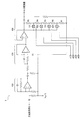
図1は、計測装置の一例の構成を示す図である。図1に示される計測装置102は、計測対象(例えば被検体としての人:不図示)の情報を含む信号を出力する、センサー素子としての光電変換部2と、計測対象の情報を含む信号を増幅する増幅器3と、サンプリング部としてのA/D変換器4と、を含むセンサー部10と、センサー部10から出力されるセンサー信号dxの、所定期間における最大値と最小値との差分を振幅値として検出し、振幅値が所定の許容振幅値(ダイナミックレンジ)に占める割合の程度に基づいて、センサー部10の感度を調整する感度調整部6と、タイミング制御情報を出力するタイミング部(タイマー等)9と、振幅閾値を格納している閾値格納部11と、周波数解析部50と、を有する。サンプリング部としてのA/D変換器4は、増幅器3から出力される信号を所定時間間隔でサンプリングしてサンプルを抽出する。
(First embodiment)
(Configuration of measuring device)
FIG. 1 is a diagram illustrating a configuration of an example of a measurement apparatus. The
増幅器3は可変利得増幅器である。増幅器3のゲインGNは、感度調整部6によって調整(制御)される。
The
感度調整部6は、センサー信号dxの振幅値の、センサー信号dxの許容振幅値(ダイナミックレンジ)に対する割合の程度に基づいて、増幅器3のゲインを定める情報であるゲイン設定値を決定するゲイン設定値決定部7と、ゲイン設定値決定部7によって決定されたゲイン設定値に基づいて、増幅器3のゲインGNを調整するゲイン調整部8と、を有していることが好ましい。なお、感度調整部6は、センサー部10の感度の調整に際して、例えば、周波数解析部50から出力される、センサー信号dxの周波数解析結果を示す信号gxを参照してもよい。
The
ゲイン設定値決定部7は、ゲインGNを増加させる場合においてゲイン設定値を決定する第1決定部7aと、ゲインGNを減少させる場合においてゲイン設定値を決定する第2決定部7bと、を有する。つまり、ゲイン設定値決定部7は、ゲインGNを増加させる場合ならびに減少させる場合の双方において、適切なゲイン設定値を決定することができる。ゲイン設定値決定部7によってゲイン設定値の値が決定されると、ゲイン調整部8は、ゲイン設定値に基づいて増幅器3のゲインGNを調整する。これによって、増幅器3のゲインGNを、ゲイン設定値というパラメーターによって制御することができる。
The gain setting
次に、増幅器(可変利得増幅器)3の具体的な構成例について説明する。図2は、増幅器の具体的な構成の一例を示す図である。増幅器3は、センサー素子である光電変換部2から出力された信号を、一定のゲインで増幅する初段増幅部410と、所定周波数以下の周波数成分を除去するローパスフィルタ420と、可変ゲイン増幅部430と、をカスケード接続して構成される。
Next, a specific configuration example of the amplifier (variable gain amplifier) 3 will be described. FIG. 2 is a diagram illustrating an example of a specific configuration of the amplifier. The
可変ゲイン増幅部430は、ゲイン調整信号d1〜d4の信号レベルによってオン/オフが制御されるアナログスイッチ431〜434を有する。ここで、アナログスイッチ431〜434は、対応するゲイン調整信号(d1〜d4のいずれか)のレベルがHレベルとなった場合にオンする。
The variable
なお、ゲイン調整信号d1〜d4のうちの1つの信号レベルがHレベルとなるときは、他のゲイン調整信号の信号レベルはLレベルとなる。したがって、アナログスイッチ431〜434は、いずれかひとつのみがオンされる。 When the signal level of one of the gain adjustment signals d1 to d4 is H level, the signal level of the other gain adjustment signal is L level. Accordingly, only one of the analog switches 431 to 434 is turned on.
ここで、フィードバック抵抗R1〜R5の抵抗値を、例えばR1=20kΩ、R2=40kΩ、R3=80kΩ、R4=160kΩ、R5=320kΩとすると、可変ゲイン増幅部430におけるゲインは、ゲイン調整信号d1がHレベルとなって、アナログスイッチ431がオンした場合に2倍となり、また、ゲイン調整信号d2がHレベルとなって、アナログスイッチ432がオンした場合には4倍となる。また、ゲイン調整信号d3がHレベルとなって、アナログスイッチ433がオンした場合には8倍となり、また、ゲイン調整信号d4がHレベルとなって、アナログスイッチ434がオンした場合に16倍となる。各オペアンプは片電源で動作するため、入力信号が電源電圧VDDの半分の電圧VDD/2にプルアップされている。以上の構成は一例であり、適宜、変形、応用が可能である。
Here, assuming that the resistance values of the feedback resistors R1 to R5 are, for example, R1 = 20 kΩ, R2 = 40 kΩ, R3 = 80 kΩ, R4 = 160 kΩ, and R5 = 320 kΩ, the gain in the variable
(初回のゲイン調整動作)
次に、計測開始後、増幅器3のゲインGNを初めて調整する場合(つまり、初回のゲイン調整動作)について説明する。図3〜図6を参照して説明する。
(First gain adjustment operation)
Next, the case where the gain GN of the
上述のとおり、感度調整部6は、センサー信号dxの振幅値が所定の許容振幅値(ダイナミックレンジ)に占める割合の程度に基づいて、センサー部10の感度を調整(制御)する。所定期間(例えば、計測開始後0秒〜4秒の期間)におけるセンサー信号dxの振幅値は、所定期間における最大値と最小値との差分値によって定まる。
As described above, the
また、所定の許容振幅値は、上述のとおり、例えばセンサー信号dxの値が取り得る範囲を規定するダイナミックレンジに相当する。センサー部10の感度は、増幅器3のゲインに応じて決定される。すなわち、増幅器3のゲインを調整することによって、センサー部10の感度を調整することができる。
Further, as described above, the predetermined allowable amplitude value corresponds to, for example, a dynamic range that defines a range that the value of the sensor signal dx can take. The sensitivity of the
感度調整部6は、センサー信号dxの振幅が、許容振幅値(ダイナミックレンジ)に対してどのような割合になっているかを検出する。したがって、例えば、センサー信号dxの振幅が、許容振幅値(ダイナミックレンジ)内で、可能な限り大きくなるように(例えば、最大となるように)、増幅器3のゲインを設定することができる。したがって、増幅器3のゲインを、計測対象の初期状態に対応する適切なゲイン(例えば可能な限り大きなゲイン)に設定することができる。
The
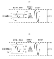
図3(A)および図3(B)は、ゲイン調整の例(ゲインを増大させる例)を模式的に示す図である。図3(A)および図3(B)の例では、ゲイン設定値を4(初期値)として計測を開始する。この場合の増幅器3のゲインGNは16(=24)となる。また、所定期間(例えば、計測開始後0秒〜4秒の期間)におけるセンサー信号dxの振幅値をQ1aとする。センサー信号dxの振幅値Q1aは、最大値M2と最小値M1との差分によって決定される。なお、センサー信号dxが取り得る許容振幅値(ダイナミックレンジ)はDLである。この許容振幅値DLの下限値はLLであり、上限値はLU(具体的には512)である。
FIG. 3A and FIG. 3B are diagrams schematically illustrating an example of gain adjustment (an example in which gain is increased). In the example of FIGS. 3A and 3B, the measurement is started with the gain setting value set to 4 (initial value). In this case, the gain GN of the
ここで、感度調整部6(具体的には、ゲイン設定値決定部7の第1決定部7a)は、センサー信号dxの振幅値Q1aを、例えば、5つの振幅閾値(16,32,64,128,256の各値をもつ第1振幅閾値〜第5振幅閾値)と比較し、これによって、センサー信号dxの振幅値Q1aが許容振幅値DLに占める割合の程度を判断する。
Here, the sensitivity adjustment unit 6 (specifically, the
ここでは、センサー信号dxの許容振幅値の中点の値を0とし、かつ上限値を512(=29)とする。また、上述の所定期間におけるセンサー信号dxの振幅値(上述のQ1a)をxとし、振幅閾値の値をyとしたとき、感度調整部に含まれるゲイン設定値決定部7の第1決定部7aは、x<yを満足する最小のyに相当する振幅閾値を、第1振幅値〜第5振幅値の中から特定する。
Here, the midpoint value of the allowable amplitude value of the sensor signal dx is set to 0, and the upper limit value is set to 512 (= 2 9 ). Further, when the amplitude value (Q1a) of the sensor signal dx in the predetermined period is x and the amplitude threshold value is y, the
この結果、図3(A)の例では、第1振幅閾値(値16)が特定される。ゲイン設定値決定部7の第1決定部7aは、特定された振幅閾値に応じて、ゲイン設定値(ここではmとする)の値を決める。図3(A)の例では、ゲイン設定値m=9と決定される。
As a result, in the example of FIG. 3A, the first amplitude threshold value (value 16) is specified. The
また、ゲイン調整部8は、増幅器3のゲインをGNとするとき、GN=2mという計算式に基づいて定まる値となるように、増幅器3のゲインGNを調整する。この調整のタイミングは、例えば、上述の所定期間(計測開始後0秒〜4秒の期間)が終了した時点である。図3(A)の例では、ゲインGNは512(=29)に調整される。これは、ゲイン設定値m=4のときのゲインGNの32倍に相当する。
Further, the
また、図3(B)の例では、センサー信号dxの振幅値はQ1bである。この場合、振幅閾値として、第5振幅閾値(値256)が選択される。この場合、ゲイン設定値mは5と決定される。これによって、増幅器3のゲインGNは、32(=25)に調整される。これは、ゲイン設定値m=4のときのゲインGNの2倍に相当する。
In the example of FIG. 3B, the amplitude value of the sensor signal dx is Q1b. In this case, the fifth amplitude threshold (value 256) is selected as the amplitude threshold. In this case, the gain setting value m is determined to be 5. As a result, the gain GN of the
このようにして、計測開始後、所定期間が経過した時点で、初回のゲイン調整が実行されて、増幅器3のゲインGNは適切な値に調整される。すなわち、早期かつ適切な初回のゲイン調整が実現される。
In this way, when a predetermined period elapses after the start of measurement, the first gain adjustment is executed, and the gain GN of the
図4(A)および図4(B)は、ゲイン調整の例(ゲインを減少させる例)を模式的に示す図である。図4(A)および図4(B)の例では、ゲイン設定値を4(初期値)として計測を開始する。この場合の増幅器3のゲインGNは16(=24)となる。また、所定期間(例えば、計測開始後0秒〜4秒の期間)におけるセンサー信号dxの振幅値をQ1aとする。センサー信号dxの振幅値Q1aは、最大値M2と最小値M1との差分によって決定される。なお、センサー信号dxが取り得る許容振幅値(ダイナミックレンジ)はDLである。この許容振幅値DLの下限値はLLであり、上限値はLU(具体的には512)である。
4A and 4B are diagrams schematically illustrating an example of gain adjustment (an example in which gain is decreased). In the example of FIGS. 4A and 4B, the measurement is started with the gain setting value set to 4 (initial value). In this case, the gain GN of the
増幅器3のゲインGNを減少させる場合は、ゲイン設定値決定部7の第2決定部7bが、ゲイン設定値mの値を特定する。感度調整部6は、ゲインGNをどの程度、減少させるかを判断するために、例えば、センサー信号dxの振幅値が、所定の許容振幅値DL(LL,LU)を超えるか否かを検出し、検出結果に基づいてセンサー部10の感度調整を実行する。なお、センサー信号dxの振幅値が所定の許容振幅値(ダイナミックレンジ)を超える現象を「振り切れ」といってもよい。
When reducing the gain GN of the
例えば、感度調整部6は、所定期間(例えば、計測開始後0秒〜4秒の期間)において、センサー信号dxの振幅値が、所定の許容振幅値DLを超える振り切れが生じたか否かを検出し、振り切れの有無に基づいて、センサー部10の感度を調整してもよい。なお、感度調整の具体例については、図6を用いて後述する。
For example, the
振り切れが生じたとき、増幅器3から出力されるセンサー信号dxの値は、飽和した状態となっている。振り切れが生じていることは、所定の振幅許容値(ダイナミックレンジ)を超える過大な信号が増幅器に入力されていることを意味する。図4(A)の例では、振り切れが生じている。
When the shakeout occurs, the value of the sensor signal dx output from the
この場合、感度調整部6が、増幅器3のゲインGNを減少させることによって、振り切れが生じないようにすることができる。
In this case, the
また、所定期間において、センサー信号dxの振幅値が所定の許容振幅値DLを超える振り切れが、時系列において隣り合う複数のサンプル(時系列において連続する複数のサンプルといってもよい)について生じた場合には、感度調整部6は、隣り合う複数のサンプルについての振り切れが、所定期間において生じた回数を検出し、回数に基づいて、センサー部10の感度を調整してもよい。
In addition, in the predetermined period, the fluctuation of the amplitude of the sensor signal dx exceeding the predetermined allowable amplitude value DL occurred for a plurality of samples adjacent in the time series (may be referred to as a plurality of samples consecutive in the time series). In this case, the
増幅器3に入力される信号の乱れの程度が大きいほど、振り切れの回数が増大する可能性が高いと考えられる。よって、感度調整部6が、振り切れの回数に基づく増幅器3のゲインGNの調整(ゲインを適切に減少させる処理)を実行することによって、振り切れが生じないようにすることができる。
It is considered that the greater the degree of disturbance of the signal input to the
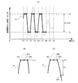
図4(A)の例では、上限値LU側における振り切れが3回連続しており(時刻t10〜t11,時刻t12〜t13,時刻t14〜t15)、下限値LL側における振り切れも3回連続している(時刻t11〜t12,時刻t13〜t14,時刻t15〜t16)。この場合は、振り切れの回数は3となる。 In the example of FIG. 4A, the swing-out on the upper limit LU side is continued three times (time t10 to t11, time t12 to t13, time t14 to t15), and the swing-off on the lower limit value LL side is continued three times. (Time t11 to t12, time t13 to t14, time t15 to t16). In this case, the number of shakeouts is 3.
また、所定期間において、センサー信号dxの振幅値が所定の許容振幅値を超える振り切れが、隣り合う複数のサンプルについて生じた場合、感度調整部6は、時系列において隣り合うサンプル数が最大である振り切れにおけるサンプル数を最大サンプル数として検出し、最大サンプル数に基づいて、センサー部10の感度を調整してもよい。
In addition, in the predetermined period, when the fluctuation of the amplitude of the sensor signal dx exceeding the predetermined allowable amplitude value occurs in a plurality of adjacent samples, the
増幅器3に入力される信号の過大さの程度が増大するほど、最大サンプル数が多くなる可能性が高いと考えられる。よって、感度調整部6が、最大サンプル数に基づく増幅器3のゲインGNの調整(この場合は、ゲインを適切に減少させる処理)を実行することによって、振り切れが生じないようにすることができる。
It is considered that the maximum number of samples is likely to increase as the degree of excessiveness of the signal input to the
例えば、時系列において隣り合うサンプル数が最大である振り切れが、図4(B)に示されるような振り切れであったとする。この場合、サンプルSP1〜SP3が連続していることから、時系列において隣り合う最大のサンプル数は3となる。 For example, it is assumed that the shakeout with the maximum number of adjacent samples in the time series is a shakeout as shown in FIG. In this case, since the samples SP1 to SP3 are continuous, the maximum number of adjacent samples in the time series is 3.
また、所定期間において、センサー信号dxの振幅値が所定の許容振幅値を超える振り切れが生じたとき、感度調整部6は、センサー信号dxの振幅値が所定の許容振幅値の上限値LUを超えるか、あるいは、所定の許容振幅値の下限値LLを超えるか、に基づいて、センサー部10の感度を調整してもよい。
In addition, when the amplitude of the sensor signal dx exceeds the predetermined allowable amplitude value during the predetermined period, the
ここで、センサー信号dxの振幅値が所定の許容振幅値の上限値LUを超える現象を、「正方向の振り切れ」といってもよく、また、センサー信号dxの振幅値が所定の許容振幅値の下限値LLを超える現象を「負方向の振り切れ」といってもよい。 Here, the phenomenon in which the amplitude value of the sensor signal dx exceeds the upper limit LU of the predetermined allowable amplitude value may be referred to as “positive swing out”, and the amplitude value of the sensor signal dx is the predetermined allowable amplitude value. A phenomenon that exceeds the lower limit LL of “N” may be referred to as “negative swing out”.
振り切れが生じたときに、その方向の情報を含めて検出することによって、センサー部10の感度GNを調整する際の基礎となる情報が増える。よって、増幅器3の感度GNを的確に調整できる。
By detecting the direction including the information of the direction when the shake is lost, the information that is the basis for adjusting the sensitivity GN of the
図4(A)の例では、正方向の振り切れが、時刻t10〜t11、時刻t12〜t13、時刻t14〜t15において生じている。また、負方向の振り切れが、時刻t11〜t12、時刻t13〜t14、時刻t15〜t16において生じている。 In the example of FIG. 4A, the forward swing is generated at time t10 to t11, time t12 to t13, and time t14 to t15. In addition, the negative swing occurs at times t11 to t12, times t13 to t14, and times t15 to t16.
また、所定期間において、センサー信号dxの振幅値が許容振幅値DLを超えたとき、所定の許容振幅値を超えたサンプルの振幅値と、所定の許容振幅値を超えたサンプルに隣り合う、所定の許容振幅値を超えていないサンプル(振り切れを起こしていないサンプル)の振幅値との差分を検出し、差分に基づいて、センサー部10の感度を調整してもよい。
In addition, when the amplitude value of the sensor signal dx exceeds the allowable amplitude value DL in a predetermined period, the amplitude value of the sample exceeding the predetermined allowable amplitude value and the sample exceeding the predetermined allowable amplitude value are adjacent to each other. A difference from the amplitude value of a sample that does not exceed the permissible amplitude value (a sample that has not been shaken out) may be detected, and the sensitivity of the
例えば、振り切れを生じさせた信号(増幅器3への入力信号)の波形が先鋭であるほど、差分が大きくなると考えられる。ここで、信号の波形の先鋭度が高い場合と低い場合とを想定する。この場合、増幅器3から出力されるセンサー信号dxの振幅値を、許容振幅値DL内に納めるためには、先鋭度が高いときの方が、増幅器3のゲインGNをより小さくしないといけないと考えられる。感度調整部6が、差分に着目して、増幅器3のゲインGNを調整することによって、振り切れが生じないようにすることができる。
For example, it is considered that the difference becomes larger as the waveform of the signal (input signal to the amplifier 3) causing the shake-out is sharper. Here, it is assumed that the sharpness of the waveform of the signal is high and low. In this case, in order to keep the amplitude value of the sensor signal dx output from the
図4(C)の例では、振り切れを起こしたサンプルSP3と、このサンプルSP3に隣り合い、振り切れを起こしていないサンプルSP4との差分はdmである。感度調整部6は、この差分dmを、例えば所定の閾値と比較することによって、差分dmの大きさを判断することができる。
In the example of FIG. 4C, the difference between the sample SP3 that has been shaken off and the sample SP4 that is adjacent to the sample SP3 and has not been shaken off is dm. The
次に、初回のゲイン調整のタイミングの一例について説明する。図5は、ゲイン調整のタイミングの一例を示す図である。図5には、センサー信号dxの信号波形が示されている。図5において、横軸は計測開始時点からの経過時間(秒)を示し、縦軸は、センサー信号dxの振幅値を示す。 Next, an example of the timing of the first gain adjustment will be described. FIG. 5 is a diagram illustrating an example of gain adjustment timing. FIG. 5 shows a signal waveform of the sensor signal dx. In FIG. 5, the horizontal axis indicates the elapsed time (seconds) from the measurement start time, and the vertical axis indicates the amplitude value of the sensor signal dx.
図5では、計測装置102が計測を開始した計測開始時点を時刻t0とする。この時刻t0から第1時間T1が経過した時点を第1時点(時刻t1)とし、第1時点(時刻t1)から第2時間T2が経過した時点を第2時点(時刻t2)とする。また、計測開始時点(時刻t0)から第2時点(時刻t2)までを第1期間TXとする。
In FIG. 5, the measurement start time when the
第1時間をT1、第2時間T2、第1期間TXの間には、0≦T1<TX、ならびに0<T2≦TXという関係が成立する。 A relationship of 0 ≦ T1 <TX and 0 <T2 ≦ TX is established between the first time T1, the second time T2, and the first period TX.
感度調整部6は、第1期間TXにおいては、センサー部10の感度を所定の初期設定感度とする(例えば、増幅器3のゲインGNを16とする)。また、所定期間としての第1時点(時刻t1)から第2時点(時刻t2)までの期間(第2時間T2)において、センサー信号dxの振幅値が、許容振幅値DL(−512〜512)に占める割合の程度を検出する。そして、感度調整部6は、第2時点(時刻t2)において、センサー部10の感度GNを、検出された振幅値が所定の許容振幅値に占める割合の程度に基づいて決定された感度に調整する。
In the first period TX, the
すなわち、上述の例では、計測開始時点(時刻t0)から、第1期間(TX)が経過した時点で、増幅器3のゲインGNは、計測対象の状態に応じた適切な値に調整される。第1期間(TX)の長さを適切に設定すれば、計測開始後、早期に増幅器3のゲインの最適化が可能である。上述の例では、第1時間TXは4秒に設定されている。よって、増幅器3の初期ゲイン設定を、正確かつ迅速に行うことができる。
That is, in the above example, the gain GN of the
また、計測開始当初の期間では、例えば回路動作の開始等に伴うノイズが生じ易い。図5の例では、計測開始時点から第1時点(時刻t1)までの第1時間T1を適切な長さに設定すること、すなわち、第1時間T1内で、過大なノイズが生じ易い時期が終了するようにすることによって、センサー信号dxの振幅値が所定の許容振幅値DLに占める割合の程度の検出の精度を高めることができる。 In the initial period of measurement, for example, noise accompanying the start of circuit operation is likely to occur. In the example of FIG. 5, the first time T1 from the measurement start time to the first time (time t1) is set to an appropriate length, that is, there is a time when excessive noise is likely to occur within the first time T1. By terminating the processing, it is possible to improve the detection accuracy to the extent that the amplitude value of the sensor signal dx occupies the predetermined allowable amplitude value DL.
図5の例では、センサー信号dxの過大なノイズ(過渡応答ノイズ等)は、第1時間T1内で収束しており、よって、過大なノイズによる初回ゲイン設定への悪影響は回避されている。 In the example of FIG. 5, excessive noise (transient response noise or the like) of the sensor signal dx has converged within the first time T1, and therefore, an adverse effect on the initial gain setting due to excessive noise is avoided.
(ゲイン調整の具体例)
次に、ゲイン調整の具体例について図6を用いて説明する。図6(A)および図6(B)は、ゲイン調整の具体例を示す図である。
(Specific example of gain adjustment)
Next, a specific example of gain adjustment will be described with reference to FIG. 6A and 6B are diagrams illustrating specific examples of gain adjustment.
図6(A)は、ゲインを増大させる場合の具体例を示している。この例では、センサー信号dxの許容振幅値(ダイナミックレンジ)を0〜1023(10bit分)としている。図6(A)の例では、ケース1〜ケース5の各々について、使用される振幅閾値と、ゲイン設定と、必要な感度(GN)と、振幅値の上限値と、が示されている。
FIG. 6A shows a specific example when the gain is increased. In this example, the allowable amplitude value (dynamic range) of the sensor signal dx is set to 0 to 1023 (for 10 bits). In the example of FIG. 6A, the amplitude threshold value, gain setting, required sensitivity (GN), and upper limit value of the amplitude value are shown for each of
図6(A)の例では、センサー信号dxの許容振幅値の中点の値を0とし、正方向に最大で512のレンジを設定し、負方向に−512のレンジを設定している。 In the example of FIG. 6A, the midpoint value of the allowable amplitude value of the sensor signal dx is set to 0, a maximum range of 512 is set in the positive direction, and a range of −512 is set in the negative direction.
また、増幅器3のゲイン設定値をm(mは、4≦m≦9を満足する自然数)とし、計測装置102の計測開始時点における増幅器3のゲイン設定値mの値(つまり、初期設定値)を4とし、このときの増幅器3のゲイン(つまり、初期設定ゲイン)を16(=24)とする。
The gain setting value of the
また、所定期間におけるセンサー信号dxの振幅値の、許容振幅値に対する割合の程度を判断する基準となる振幅閾値として、値が16の第1振幅閾値、値が32の第2振幅閾値、値が64の第3振幅閾値、値が128の第4振幅閾値、値が256の第5振幅閾値を用いる。 In addition, as an amplitude threshold value serving as a reference for determining the degree of the ratio of the amplitude value of the sensor signal dx in the predetermined period to the allowable amplitude value, a first amplitude threshold value of 16, a second amplitude threshold value of 32, and a value of A third amplitude threshold value of 64, a fourth amplitude threshold value of 128, and a fifth amplitude threshold value of 256 are used.
ここで、所定期間におけるセンサー信号dxの振幅値をxとし、振幅閾値の値をyとしたとき、ゲイン設定値決定部7の第1決定部7aは、x<yを満足する最小のyに相当する振幅閾値を、第1振幅値〜前記第5振幅値の中から特定する。
Here, when the amplitude value of the sensor signal dx in the predetermined period is x and the amplitude threshold value is y, the
(ケース1)
第1決定部7aは、特定された振幅閾値が第1振幅閾値(値16)のとき、増幅器3のゲイン設定値mの値を9とする。ゲイン調整部8は、増幅器3のゲイン設定値mの値が9のとき、増幅器のゲインGNを512(=29)とする。
(Case 1)
The
(ケース2)
第1決定部7aは、特定された振幅閾値が第2振幅閾値(値32)のとき、増幅器3のゲイン設定値mの値を8とする。ゲイン調整部8は、増幅器3のゲイン設定値mの値が8のとき、増幅器3のゲインGNを256(=28)とする。
(Case 2)
The
(ケース3)
第1決定部7aは、特定された振幅閾値が第3振幅閾値(値64)のとき、増幅器3のゲイン設定値mの値を7とする。ゲイン調整部8は、増幅器3のゲイン設定値mの値が7のとき、増幅器3のゲインを128(=27)とする。
(Case 3)
The
(ケース4)
第1決定部7aは、特定された振幅閾値が第4振幅閾値(値128)のとき、増幅器3のゲイン設定値mの値を6とする。ゲイン調整部8は、増幅器3のゲイン設定値mの値が6のとき、増幅器のゲインを64(=26)とする。
(Case 4)
The
(ケース5)
第1決定部7aは、特定された振幅閾値が第5振幅閾値(値256)のとき、増幅器3のゲイン設定値mの値を5とする。ゲイン調整部8は、増幅器3のゲイン設定値mの値が5のとき、増幅器のゲインを32(=25)とする。
(Case 5)
The
(ケース6)
センサー信号dxの振幅値が、第5振幅閾値(値256)よりも大きいときがケース6なる。この場合には、図6(B)に従って、振り切れ回数等を考慮したゲイン調整(ゲインを減少させる調整)が実行される。
(Case 6)
このように、図6(A)の例では、感度調整部6は、センサー信号dxを、5つの振幅閾値(16,32,64,128,256の各値をもつ第1振幅閾値〜第5振幅閾値)と比較することによって、「センサー信号dxの振幅値が所定の許容振幅値に占める割合の程度」を判断する。
As described above, in the example of FIG. 6A, the
ここでは、センサー信号dxの許容振幅値の中点の値を0とし、かつ上限値を512(=29)とする。また、所定期間におけるセンサー信号dxの振幅値をxとし、振幅閾値の値をyとしたとき、感度調整部に含まれるゲイン設定値決定部は、x<yを満足する最小のyに相当する振幅閾値を、第1振幅値〜第5振幅値の中から特定する。 Here, the midpoint value of the allowable amplitude value of the sensor signal dx is set to 0, and the upper limit value is set to 512 (= 2 9 ). Further, when the amplitude value of the sensor signal dx in the predetermined period is x and the amplitude threshold value is y, the gain setting value determination unit included in the sensitivity adjustment unit corresponds to the minimum y satisfying x <y. An amplitude threshold value is specified from the first amplitude value to the fifth amplitude value.
そして、ゲイン設定値決定部7(第1決定部7a)は、特定された振幅閾値が、第1振幅閾値〜第5振幅値のうちのどれであるかに応じて、増幅器3のゲイン設定値mの値を決める。また、増幅器3のゲインをGNとするとき、ゲイン調整部8は、GN=2mという計算式に基づいて定まる値となるように、増幅器3のゲインGNを調整する。図6(A)の例によれば、センサー信号dxを、複数の振幅閾値と比較し、その比較結果に応じて、増幅器3のゲイン設定値mの値、ならびに増幅器3のゲインGNを算出することができる。
Then, the gain setting value determination unit 7 (
図6(B)の例では、ゲインを減少させる場合の具体例が示されている。図6(B)の例では、センサー信号dxの許容振幅値の中点の値を0とし、正方向に最大で512のレンジを設定し、負方向に−512のレンジを設定している。この範囲に収まらない場合を、振り切れと呼んでいる。ここで、正方向の振り切れとは、センサー信号dxの振幅値が、ダイナミックレンジの上限値(512)を超える場合であり、負方向の振り切れとは、ダイナミックレンジの下限値(−512)を超えて下回った場合である。なお、図6(B)の例では、計測開始後の最初のゲイン設定値見直し処理では、ゲイン設定値mを0にはしないようにしている。 In the example of FIG. 6B, a specific example in the case of decreasing the gain is shown. In the example of FIG. 6B, the midpoint value of the allowable amplitude value of the sensor signal dx is set to 0, a maximum range of 512 is set in the positive direction, and a range of −512 is set in the negative direction. A case that does not fall within this range is called a shakeout. Here, the shake in the positive direction is a case where the amplitude value of the sensor signal dx exceeds the upper limit value (512) of the dynamic range, and the shake in the negative direction exceeds the lower limit value (−512) of the dynamic range. Is less than In the example of FIG. 6B, the gain setting value m is not set to 0 in the first gain setting value review process after the start of measurement.
図6(A)に従う判断によって、ケース6と判断されたとき、ゲイン設定値決定部7の第2決定部7bは、図6(B)に従う判断を実行して、ゲイン設定値mの値を決定する。
When it is determined as
(ケース7)
正方向の振り切れ回数と、負方向の振り切れ回数とを加算した値が10以上であるときは、ゲイン設定値mを1とする。
(Case 7)
The gain setting value m is set to 1 when the value obtained by adding the number of swings in the positive direction and the number of swings in the negative direction is 10 or more.
(ケース8)
連続した振り切れの回数が4以上であるときは、ゲイン設定値mを1とする。
(Case 8)
The gain setting value m is set to 1 when the number of consecutive shakeouts is 4 or more.
(ケース9)
センサー信号dxの振幅値が所定の許容振幅値を超えた、時系列において隣り合うサンプル数が最大となる最大サンプル数が3以上のときは、ゲイン設定値mを1とする。
(Case 9)
The gain setting value m is set to 1 when the amplitude value of the sensor signal dx exceeds a predetermined allowable amplitude value and the maximum number of samples adjacent to each other in the time series is the maximum.
(ケース10)
振り切れを起こしたサンプルと、このサンプルに隣り合うサンプルとの差分(振り切れサンプル差分)が128以上であるときは、ゲイン設定値mを1とする。
(Case 10)
The gain setting value m is set to 1 when the difference between the sample that caused the shakeout and the sample adjacent to this sample (the shakeout sample difference) is 128 or more.
(ケース11)
正方向の振り切れ回数が2以上、あるいは、負方向の振り切れ回数が2以上であるときは、ゲイン設定値mを3とする。但し、これは一例であり、変形が可能である。例えば、正方向の振り切れの場合と負方向の振り切れの場合とで、調整された感度に差を設けてもよい。
(Case 11)
The gain setting value m is set to 3 when the number of swing-outs in the positive direction is 2 or more, or when the number of swing-outs in the negative direction is 2 or more. However, this is only an example and can be modified. For example, a difference may be provided in the adjusted sensitivity between the case where the swing is positive and the case where the swing is negative.
(ケース12)
振り切れを起こしたサンプルと、このサンプルに隣り合うサンプルとの差分(振り切れサンプル差分)が64以上であるときは、ゲイン設定値mを2とする。
(Case 12)
The gain setting value m is set to 2 when the difference between the sample that has shaken off and the sample adjacent to this sample (the shaken sample difference) is 64 or more.
(ケース13)
正方向の振り切れ回数が1以上、あるいは、負方向の振り切れ回数が1以上であるときは、ゲイン設定値mを3とする。
(Case 13)
The gain setting value m is set to 3 when the number of shakes in the positive direction is 1 or more or the number of shakes in the negative direction is 1 or more.
(ケース14)
振り切れは無いが、センサー信号dxのピーク値が、ダイナミックレンジ(−512〜512)のうちの388以上ならば、ゲイン設定値mを3とする。
(Case 14)
Although there is no shaking, the gain setting value m is set to 3 if the peak value of the sensor signal dx is 388 or more of the dynamic range (−512 to 512).
(ケース15)
振り切れは無いが、センサー信号dxのピーク値が、ダイナミックレンジ(−512〜512)のうちの388未満ならば、ゲイン設定値mを4とする。
(Case 15)
Although there is no shaking, the gain setting value m is set to 4 if the peak value of the sensor signal dx is less than 388 in the dynamic range (−512 to 512).
図6(B)に示される、各判断条件は一例であり、また、各判断条件のいずれかのみを使用することもでき、また、複数の判断条件を任意に組み合わせて使用することも可能である。 Each judgment condition shown in FIG. 6B is an example, and only one of the judgment conditions can be used, or a plurality of judgment conditions can be used in any combination. is there.
(第2実施形態)
本実施形態では、計測装置の一例としての拍動検出装置の構成ならびに動作について説明する。本実施形態では、例えば、増幅器の初期ゲイン設定の高精度化ならびに迅速化が実現される。よって、本実施形態の拍動検出装置は、拍動信号の検出に使用できる有用な脈波信号(センサー信号に相当する)を得ることができる。よって、拍動検出装置の拍動検出の精度が高まる。
(Second Embodiment)
In the present embodiment, the configuration and operation of a pulsation detection device as an example of a measurement device will be described. In the present embodiment, for example, high accuracy and quickness of the initial gain setting of the amplifier are realized. Therefore, the pulsation detection device of the present embodiment can obtain a useful pulse wave signal (corresponding to a sensor signal) that can be used for detecting a pulsation signal. Therefore, the accuracy of beat detection of the beat detection device is increased.
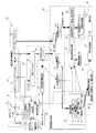
図7は、拍動検出装置の一例の構成を示す図である。図7において、図1と共通する部分には、同じ参照符号を付し、その説明を省略してある。図7に示される拍動検出装置100は、被検体(人や動物を含む)の拍動に由来する拍動信号、拍動信号に対応する心拍等の生体情報等を検出するセンサー装置の一種である。
FIG. 7 is a diagram illustrating a configuration of an example of a pulsation detection device. In FIG. 7, the same reference numerals are given to portions common to FIG. 1, and description thereof is omitted. A
ここで、拍動とは、医学的には心臓のみならず内臓一般の周期的な収縮、弛緩が繰り返された場合に起こる運動のことをいう。ここでは、心臓が周期的に血液を送るポンプとしての動きを拍動と呼ぶ。なお、心拍数とは、1分間の心臓の拍動の数をいう。また、脈拍数は、末梢血管における脈動の数をいう。心臓が血液を送り出す際に、動脈に脈動が生じるので、この回数を数えたものを脈拍数あるいは単に脈拍と呼ぶ。腕で脈を計測する限りは、医学的には心拍数とは呼ばずに脈拍数と呼ぶのが通常である。また、以下の説明では、体動という用語が使用される。体動とは、広い意味では、体を動かすことすべてを意味する(広義の体動)。被検体の定常的、周期的な体動(例えば、歩行・ジョギングなどに伴う周期的、つまり定常的な腕(例えば拍動検出装置の本体の近辺)の動き等)を、狭義の体動といってもよい。 Here, the pulsation means a movement that occurs when the periodical contraction and relaxation of not only the heart but also the internal organs are repeated medically. Here, the movement as a pump in which the heart periodically sends blood is called pulsation. The heart rate refers to the number of heart beats per minute. The pulse rate refers to the number of pulsations in the peripheral blood vessels. When the heart pumps out blood, pulsation occurs in the artery, and this number is called the pulse rate or simply the pulse. As long as the pulse is measured with an arm, it is usually referred to as a pulse rate instead of a heart rate in medical terms. Moreover, in the following description, the term body movement is used. Body movement means, in a broad sense, all movement of the body (broad movement in a broad sense). The subject's steady and periodic body movements (for example, the movement of the arm (for example, the vicinity of the body of the pulsation detecting device) that is periodic, such as walking or jogging) is defined as a narrowly defined body movement. May be.
(全体構成)
図7に示される拍動検出装置100は、拍動信号を含む可能性がある脈波信号dを出力する脈波センサー部10と、感度調整部6と、タイミング部(タイマー)9と、閾値格納部(メモリー)11と、脈波信号蓄積部(4秒分の脈波信号dのデータを蓄積する第1バッファメモリー13および16秒分の脈波信号dのデータを蓄積する第2バッファメモリー15を有する)12と、適応フィルター32および体動成分除去フィルター34を含むフィルター部30と、体動センサー部(加速度センサーやジャイロセンサー等)20と、体動信号蓄積部22と、周波数解析部50と、履歴格納部70と、被検体情報取得部(脈拍数・消費カロリー算出部)90と、表示処理部92と、表示部94と、を有する。
(overall structure)
A
周波数解析部50は、信号分配部39と、周波数分解部40(第1周波数分解部40a、第2周波数分解部40b、第3周波数分解部40c)ならびに周波数傾向情報44を蓄積している脈波信号解析部42と、後処理部60(ピーク順ソート部62、相関判定部64、拍動/体動分離部66、拍動呈示スペクトル特定部68とを含む)と、拍動呈示スペクトル捕捉処理部80と、を有する。
The
脈波センサー部10は、例えば、光電脈波センサー部及びその原理に基づく脈波センサー部である。脈波センサー部10は、拍動信号を含む可能性がある脈波信号d(第1実施形態におけるセンサー信号dxに相当する)を出力する。
The pulse
脈波センサー部10は、LED等の光源(不図示)と、光源の出力光が、生体情報源である血管(図1では不図示)で反射して生じる反射光を受光して電気信号に変換する、センサー素子としての光電変換部2と、光電変換部2の出力信号を増幅する増幅器(可変利得アンプ)3と、サンプリング部としてのA/D変換器4と、を有する。
The pulse
脈波センサー部10の感度は、増幅器3のゲイン(増幅率)によって決定される。増幅器3のゲイン、すなわち、脈波センサー部10の感度は、感度調整部6によって調整される。感度調整部6は、例えば、増幅器3のゲインを自動調整するAGC回路(自動利得制御回路)によって構成される。
The sensitivity of the pulse
感度調整部6は、第1バッファメモリー13に蓄積されている4秒分の脈波信号dのデータに基づいて、増幅器3の初期ゲイン調整を実行する。感度調整部6は、第1実施形態で説明した増幅器3の感度調整動作を実行する。感度調整部6は、例えば、脈波信号dの振幅値が、所定値(所定レベル)になるように、例えば、所定の許容振幅値(ダイナミックレンジ)内で最大となるように、増幅器3のゲインを調整(制御)する。なお、感度調整部6は、センサー部10の感度の調整に際して、例えば、周波数解析部50から出力される、センサー信号dxの周波数解析結果を示す信号gxを参照してもよい。
The
また、体動センサー部20は、被検体の体動を検出し、体動に由来する体動信号fを出力する。体動センサー部20も、脈波センサー部10と同様に、増幅器(不図示)を内蔵している。この増幅器のゲインを、感度調整部6と同様の構成をもつAGC回路によってフィードバック制御してもよい。
The body
脈波センサー部10から出力される脈波信号dの、4秒分の信号が、第1バッファメモリー13に蓄積される。4秒分の脈波信号dは、4秒周期で、第2バッファメモリー15に転送される。第2バッファメモリー15はFIFO(ファーストイン・ファーストアウト)メモリーであり、16秒分の脈波信号は、4秒分ずつ更新される。16秒分の脈波信号を蓄積するのは、周波数解析によって拍動成分を特定するとき、ある程度の時間幅で信号の推移を観測し、相関の有無等を慎重に検討する必要があるからである。
A signal for 4 seconds of the pulse wave signal d output from the pulse
フィルター部30は、入力信号に含まれるノイズを最小化する。また、体動成分除去フィルター34によって、例えば、脈波信号dに含まれる体動信号成分が最小化される。
The
周波数解析部50は、脈波信号d、または、脈波信号dに、脈波信号に含まれるノイズを抑制するフィルタリング(フィルター部30による)を施して得られるフィルタリング後信号eに基づいて、所定時間毎(例えば4秒毎)に周波数解析を実行して、拍動信号を示す拍動呈示スペクトルを特定する。
The
信号分配部39は、フィルター後信号eを第1周波数分解部(高速フーリエ変換部:FFT)40aに供給し、フィルター前の脈波信号dを第3周波数分解部40cに供給する。また、体動信号fは第2周波数分解部40bに供給される。
The
後処理部60は、周波数スペクトルをスペクトル値の大きい順にソーティングするピーク順ソート部62と、ピーク順が上位の主要なスペクトルが、直近の過去(例えば4秒前)の拍動信号のスペクトルとの相関判定を実行する相関判定部64と、相関判定の結果を利用して拍動信号とノイズ成分とを分離する拍動/ノイズ分離部と66と、拍動/ノイズ分離処理によってノイズから分離された拍動成分のスペクトルを、拍動呈示スペクトルとして特定する拍動呈示スペクトル特定部68と、を有する。
The
拍動呈示スペクトルの特定に成功すると、被検体情報取得部(脈拍数・消費カロリー算出部)90は、被検体の生態情報である脈拍数、および、被検体の運動に関する付随的情報である消費カロリーの少なくとも一方を算出する。脈拍数は、例えば、拍動呈示スペクトルの周波数に基づいて算出される。また、消費カロリーは、脈拍数に基づいて算出される。 If the identification of the pulsation presentation spectrum is successful, the subject information acquisition unit (pulse rate / calorie consumption calculation unit) 90 consumes the pulse rate, which is the biological information of the subject, and consumption information, which is incidental information about the subject's motion. Calculate at least one of the calories. The pulse rate is calculated based on, for example, the frequency of the pulsation presentation spectrum. The calorie consumption is calculated based on the pulse rate.
算出された被検体情報(脈拍数および消費カロリーの少なくとも一方)は、被検体情報取得部(脈拍数・消費カロリー算出部)90から表示処理部92を経由して表示部94に供給される。この結果、例えば、脈波数や消費カロリーを示す数値が、表示部94によって表示される。なお、脈拍数ではなく、検出した脈の、時間軸上における変化を信号波形やグラフの形式で表示(広義には報知)してもよい。
The calculated subject information (at least one of the pulse rate and calorie consumption) is supplied from the subject information acquisition unit (pulse rate / calorie consumption calculation unit) 90 to the
また、周波数解析部50に含まれる拍動呈示スペクトル捕捉処理部80は、例えば、拍動呈示スペクトル特定部68が、フィルター後信号eに基づく拍動呈示スペクトルの特定に失敗したときに動作を開始する。拍動呈示スペクトル捕捉処理部80は、フィルタリング前の脈波信号d(フィルタリングによる信号の減衰が生じないため、フィルター後信号よりも大きな信号値をもつ)に基づいて、例えば、過去の拍動信号の周波数傾向に基づく相関判定によって、拍動呈示スペクトルの捕捉を試みる。
Further, the pulsation presentation spectrum
脈波信号解析部42は、脈波信号dの周波数スペクトルを解析し、脈波信号dの信号状態を評価し、また、拍動信号を示す拍動呈示スペクトルの周波数傾向情報44や、周波数解析結果情報45を取得する。脈波信号dの信号状態は、例えば、脈波信号dのきれいさの程度(脈波信号dのノイズ量の程度)に基づいて評価される。脈波信号dのきれいさの程度は、評価指標を用いて評価してもよい。評価指標としては、主要な周波数スペクトルのスペクトル値の比や、標準偏差ならびに偏差値のような統計情報(統計指標)を用いてもよい。
The pulse wave
また、履歴格納部70には、特定あるいは捕捉された拍動呈示スペクトルの周波数情報や、算出された被検体情報(脈拍数や消費カロリー)が、時系列で格納されている。格納されている情報は、各部が、必要に応じて参照可能である。
The
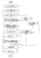
(拍動検出装置の動作例)
図8は、拍動検出装置の動作の一例を示すフローチャートである。拍動検出装置100は、増幅器3のゲイン設定値m=4(増幅器3のゲインGN=16)として、拍動信号の検出(計測)を開始する(ステップST1)。4秒分の脈波信号dは、脈波信号蓄積部12に蓄積される(ステップST2)。
(Operation example of pulsation detection device)
FIG. 8 is a flowchart showing an example of the operation of the pulsation detection device. The
次に、初回のゲイン調整タイミングであるかが判断される(ステップST3)。ここでは、検出(計測)の開始時点から4秒が経過した第2時点を、初回のゲイン調整タイミングとする。 Next, it is determined whether it is the first gain adjustment timing (step ST3). Here, a second time point when 4 seconds have elapsed from the start time of detection (measurement) is set as the first gain adjustment timing.
ステップST3でYのときは、感度調整部6による、増幅器3のゲイン調整が実行される。感度調整部6は、事前の処理として、第1バッファメモリー13に蓄積されている、検出(計測)の開始時点(経過時間0秒の時点)から3秒が経過した第1時点までに得られた脈波信号dのサンプリング値を、許容振幅値(ダイナミックレンジ)の中央値(つまり振幅中間値)に置換する(ステップST4)。すなわち、検出(計測)の開始時点から3秒が経過する第1時点までの期間では、過渡応答等によるノイズが多く含まれる可能性があることから、この期間(計測開始後0〜3秒の期間)に得られた脈波信号dの振幅値は無視し、無難な振幅値(振幅中央値)で代用し、その後の処理をし易くするものである。
When Y in step ST3, the gain adjustment of the
次に、感度調整部6は、検出(計測)の開始時点から3秒が経過した第1時点から、4秒が経過した第2時点までの期間に得られた脈波信号dのサンプリング値に基づいて、脈波信号dの振幅値が、許容振幅値(ダイナミックレンジ)に占める割合の程度を検出する(ステップST5)。この検出結果に基づいて、感度調整部6は、ゲイン設定値mを決定する(ステップST6)。これによって、増幅器3のゲインが一義的に決まる。
Next, the
次に、感度調整部6は、ステップST5の検出処理にて、振り切れが検出されたか否かを確認する(ステップST7)。ステップST7で、Yのときは、ステップST8に移行し、NのときはステップST12に移行する。ステップST8では、感度調整部6は、第1バッファメモリー13に蓄積されている、検出(計測)の開始時点から3秒が経過した第1時点から、4秒が経過した第2時点までに得られた脈波信号dのサンプリング値を、許容振幅値(ダイナミックレンジ)の中央値(つまり振幅中間値)に置換する(ステップST8)。この期間(計測開始後3秒〜4秒の期間)において振り切れが生じている場合、脈波信号dの信頼性が低いことから、脈波信号dの振幅値は無視し、無難な振幅値(振幅中央値)で代用し、その後の処理をし易くするものである。
Next, the
また、ステップST3においてNのときは、感度調整部6は、拍動信号の検出開始(計測開始)から20秒以内の期間であるかを確認する(ステップST9)。ステップST9でYのときは、増幅器3のゲインの調整処理(通常動作中のゲイン調整処理)を実行する(ステップST11)。例えば、感度調整部6は、脈波信号dのピーク値と閾値との比較に基づくゲイン調整処理を実行する。
Further, when the answer is N in step ST3, the
また、ステップST9でNのときは、感度調整部6は、前回のゲイン調整から20秒が経過しているかを判断する(ステップST10)。ステップST10で、YのときはステップST11に移行し、Nのときは、ステップST12に移行する。
If NO in step ST9, the
ステップST12では、脈拍数の算出処理等が実行される。ステップST13では、拍動検出装置100は、計測終了指示が入力されたか否かを確認する。ステップST13で、Yのときは拍動信号の処理を終了し、NのときはステップST2に戻る。
In step ST12, a pulse rate calculation process or the like is executed. In step ST13, the
(実際のゲイン調整例)
(ゲイン調整例1)
図9(A)および図9(B)は、計測開始後3秒〜4秒までの期間における脈波信号dに振り切れが生じない場合におけるゲイン調整例を示す図である。図9(A)には、計測開始後0秒〜4秒までの期間における脈波信号dの波形が示されている。横軸は、計測開始後の経過時間(秒)を示し、縦軸は脈波信号dの信号値(−512〜512)を示す。
(Example of actual gain adjustment)
(Gain adjustment example 1)
FIG. 9A and FIG. 9B are diagrams showing examples of gain adjustment in the case where the pulse wave signal d is not completely broken out during the period from 3 seconds to 4 seconds after the start of measurement. FIG. 9 (A) shows the waveform of the pulse wave signal d in the period from 0 second to 4 seconds after the start of measurement. The horizontal axis indicates the elapsed time (seconds) after the start of measurement, and the vertical axis indicates the signal value (−512 to 512) of the pulse wave signal d.
また、図9(B)には、計測開始後0秒〜16秒までの期間における脈波信号dの波形と、増幅器3のゲイン設定値の推移が示されている。図9(B)において、横軸は、計測開始後の経過時間(秒)を示し、左側の縦軸は脈波信号dの信号値(−512〜512)を示し、右側の縦軸は、ゲイン設定値mを示している。図9(B)において、増幅器3のゲイン設定値は、太い破線で示されている。
FIG. 9B shows the transition of the waveform of the pulse wave signal d and the gain setting value of the
図9(A)の例では、計測開始からの経過時間3秒〜4秒の期間では、脈波信号dのサンプリング値の最大値は503であり、最小値は478であった。振幅値(=最大値−最小値)は25となる。この場合は、図6(A)に示されるケース2に該当する。よって、ゲイン設定値mとして8が選択される。
In the example of FIG. 9A, the maximum value of the sampling value of the pulse wave signal d is 503 and the minimum value is 478 in the period of 3 seconds to 4 seconds after the start of measurement. The amplitude value (= maximum value−minimum value) is 25. This case corresponds to
この結果、図9(B)に示すように、計測開始から4秒が経過した時点以降は、ダイナミックレンジ(−512〜512)の半分ほどの振幅を持つ脈波信号dの波形を得ることができた。すなわち、計測開始後、きわめて早期に、増幅器3のゲイン(つまりセンサー部6の感度)を適正な値に調整することができた。 As a result, as shown in FIG. 9B, after 4 seconds from the start of measurement, the waveform of the pulse wave signal d having an amplitude about half of the dynamic range (−512 to 512) can be obtained. did it. That is, it was possible to adjust the gain of the amplifier 3 (that is, the sensitivity of the sensor unit 6) to an appropriate value very early after the start of measurement.
(ゲイン調整例2)
図10(A)および図10(B)は、計測開始後3秒〜4秒までの期間における脈波信号dに振り切れが生じる場合におけるゲイン調整例を示す図である。図10(A)には、計測開始後0秒〜4秒までの期間における脈波信号dの波形が示されている。横軸は、計測開始後の経過時間(秒)を示し、縦軸は脈波信号dの信号値(−512〜512)を示す。
(Gain adjustment example 2)
FIG. 10A and FIG. 10B are diagrams illustrating examples of gain adjustment in the case where the pulse wave signal d is lost in the period from 3 seconds to 4 seconds after the start of measurement. FIG. 10A shows the waveform of the pulse wave signal d in the period from 0 second to 4 seconds after the start of measurement. The horizontal axis indicates the elapsed time (seconds) after the start of measurement, and the vertical axis indicates the signal value (−512 to 512) of the pulse wave signal d.
また、図10(B)には、計測開始後0秒〜16秒までの期間における脈波信号dの波形と、増幅器3のゲイン設定値の推移が示されている。図10(B)において、横軸は、計測開始後の経過時間(秒)を示し、左側の縦軸は脈波信号dの信号値(−512〜512)を示し、右側の縦軸は、ゲイン設定値mを示している。図10(B)において、増幅器3のゲイン設定値は、太い破線で示されている。
FIG. 10B shows the transition of the waveform of the pulse wave signal d and the gain setting value of the
図10(A)の例では、計測開始からの経過時間3秒〜4秒の期間では、正方向の振り切れ回数が1回、負方向の振り切れ回数が0回、かつ脈波信号dのピーク値が1023である。この場合は、図6(B)に示されるケース13に該当する。よって、ゲイン設定値mとして3が選択される。
In the example of FIG. 10 (A), in the period of 3 to 4 seconds elapsed from the start of measurement, the number of positive swings is one, the number of negative swings is zero, and the peak value of the pulse wave signal d Is 1023. This case corresponds to
この結果、図10(B)に示すように、計測開始から4秒が経過した時点以降は、ダイナミックレンジ(−512〜512)の半分ほどの振幅を持つ脈波信号dの波形を得ることができた。すなわち、計測開始後、きわめて早期に、増幅器3のゲイン(つまりセンサー部6の感度)を適正な値に調整することができた。 As a result, as shown in FIG. 10B, after 4 seconds from the start of measurement, the waveform of the pulse wave signal d having an amplitude about half the dynamic range (−512 to 512) can be obtained. did it. That is, it was possible to adjust the gain of the amplifier 3 (that is, the sensitivity of the sensor unit 6) to an appropriate value very early after the start of measurement.
図11(A)および図11(B)は、拍動検出装置の、被検体への装着例を示す図である。 FIG. 11A and FIG. 11B are diagrams showing an example of mounting the pulsation detection device to a subject.
図11(A)の例は、腕時計型の拍動検出装置の例である。脈波センサー部10および表示部94を含むベース部400は、リストバンド300によって、被検体(ユーザー)の左手首200に装着されている。
The example of FIG. 11A is an example of a wristwatch type pulsation detecting device. A
図11(B)の例は、指装着型の拍動検出装置の例である。被検体の指先に挿入するためのリング状のガイド302の底部に、脈波センサー部10が設けられている。
The example of FIG. 11B is an example of a finger-mounted pulsation detecting device. The pulse
なお、上記のように本実施形態について詳細に説明したが、本発明の新規事項及び効果から実体的に逸脱しない多くの変形が可能であることは当業者には容易に理解できるであろう。従って、このような変形例はすべて本発明の範囲に含まれるものとする。また、明細書又は図面において、少なくとも一度、より広義又は同義な異なる用語と共に記載された用語は、明細書又は図面のいかなる箇所においても、その異なる用語に置き換えることができる。 Although the present embodiment has been described in detail as described above, it will be easily understood by those skilled in the art that many modifications can be made without departing from the novel matters and effects of the present invention. Accordingly, all such modifications are intended to be included in the scope of the present invention. In addition, a term described together with a different term having a broader meaning or the same meaning at least once in the specification or the drawings can be replaced with the different term anywhere in the specification or the drawings.
2 センサー素子としての光電変換部、3 増幅器、
4 サンプリング部としてのA/D変換器、 6 感度調整部、
7 ゲイン設定値決定部(第1決定部7a,第2決定部7bを含む)、
8 ゲイン調整部、9 タイミング部(タイマー)、11 閾値格納部(メモリー)、
10 脈波センサー部(センサー部)、12 脈波信号蓄積部、
20 体動センサー部(加速度センサーやジャイロセンサー等)、
30 フィルター部、34 体動成分除去フィルター、
40(40a〜40c) 周波数分解部、42 脈波信号解析部、
44 周波数傾向情報、45 周波数解析結果情報、50 周波数解析部、
60 後処理部、62 ピーク順ソート部、64 相関判定部、
66 拍動/体動分離部(拍動/ノイズ分離部)、68 拍動呈示スペクトル特定部、
70 履歴格納部、
80 拍動呈示スペクトル捕捉処理部、
90 被検体情報取得部(脈拍数・消費カロリー算出部)、
92 表示処理部、94 表示部、100 計測装置としての拍動検出装置
2 photoelectric conversion part as sensor element, 3 amplifier,
4 A / D converter as sampling unit, 6 Sensitivity adjustment unit,
7 Gain setting value determination unit (including the
8 gain adjustment unit, 9 timing unit (timer), 11 threshold storage unit (memory),
10 pulse wave sensor unit (sensor unit), 12 pulse wave signal storage unit,
20 Body motion sensor (acceleration sensor, gyro sensor, etc.)
30 filter section, 34 body motion component removal filter,
40 (40a to 40c) Frequency resolving unit, 42 Pulse wave signal analyzing unit,
44 frequency trend information, 45 frequency analysis result information, 50 frequency analysis section,
60 post-processing unit, 62 peak order sorting unit, 64 correlation determination unit,
66 pulsation / body motion separation unit (beat / noise separation unit), 68 pulsation presentation spectrum specifying unit,
70 history storage,
80 pulsation presentation spectrum capture processing unit,
90 Subject information acquisition unit (pulse rate / calorie consumption calculation unit),
92 display processing unit, 94 display unit, 100 pulsation detecting device as measuring device
Claims (9)
前記センサー部から出力されるセンサー信号の、所定期間における最大値と最小値との差分を振幅値として検出し、前記振幅値が所定の許容振幅値に占める割合の程度に基づいて、前記センサー部の感度を調整する感度調整部と、を有することを特徴とする計測装置。 A sensor unit that outputs a signal including information on the measurement target; and an amplifier that amplifies the signal including information on the measurement target; and
A difference between a maximum value and a minimum value in a predetermined period of a sensor signal output from the sensor unit is detected as an amplitude value, and the sensor unit is based on a degree of a ratio of the amplitude value to a predetermined allowable amplitude value. And a sensitivity adjusting unit that adjusts the sensitivity of the measuring device.
前記計測装置が計測を開始した計測開始時点から第1時間が経過した時点を第1時点とし、前記第1時点から第2時間が経過した時点を第2時点とし、前記計測開始時点から前記第2時点までを第1期間としたとき、
前記感度調整部は、
前記第1期間においては、前記センサー部の感度を所定の設定感度とし、
前記所定期間は、前記第1時点から前記第2時点までの期間とし、
かつ、前記第2時点において、検出された前記振幅値が前記所定の許容振幅値に占める割合の程度に基づいて、前記センサー部の感度を調整することを特徴とする計測装置。 The measuring device according to claim 1,
The time when the first time has elapsed from the measurement start time when the measurement device started measurement is defined as the first time point, the time when the second time has elapsed from the first time point is defined as the second time point, and the time from the measurement start time to the first time When the first period is up to 2 time points,
The sensitivity adjuster is
In the first period, the sensitivity of the sensor unit is set to a predetermined setting sensitivity,
The predetermined period is a period from the first time point to the second time point,
And the sensitivity of the said sensor part is adjusted based on the grade of the ratio for which the said detected amplitude value occupies for the said predetermined | prescribed permissible amplitude value in the said 2nd time.
前記感度調整部は、前記所定期間において、前記センサー信号の振幅値が前記所定の許容振幅値を超えるか否かを検出し、前記所定の許容振幅値を超えるか否かの検出結果に基づいて、前記センサー部の感度を調整することを特徴とする計測装置。 The measuring device according to claim 1 or 2,
The sensitivity adjustment unit detects whether or not the amplitude value of the sensor signal exceeds the predetermined allowable amplitude value in the predetermined period, and based on a detection result whether or not the predetermined value exceeds the predetermined allowable amplitude value. A measuring apparatus for adjusting the sensitivity of the sensor unit.
前記センサー部は、前記増幅器から出力される信号を所定時間間隔でサンプリングしてサンプルを抽出するサンプリング部を有し、
前記所定期間において、時系列において隣り合う複数のサンプルについて、前記センサー信号の振幅値が前記所定の許容振幅値を超える場合、前記感度調整部は、前記隣り合う複数のサンプルについて、前記センサー信号の振幅値が前記所定の許容振幅値を超えた回数を検出し、前記回数に基づいて、前記センサー部の感度を調整することを特徴とする計測装置。 The measuring device according to claim 1 or 2,
The sensor unit has a sampling unit that samples a signal output from the amplifier at a predetermined time interval to extract a sample,
When the amplitude value of the sensor signal exceeds the predetermined allowable amplitude value for a plurality of samples that are adjacent in time series in the predetermined period, the sensitivity adjustment unit is configured to output the sensor signal for the plurality of adjacent samples. A measuring device that detects the number of times an amplitude value exceeds the predetermined allowable amplitude value and adjusts the sensitivity of the sensor unit based on the number of times.
前記センサー部は、前記増幅器から出力される信号を所定時間間隔でサンプリングしてサンプルを抽出するサンプリング部を有し、
前記所定期間において、時系列において隣り合う複数のサンプルについて、前記センサー信号の振幅値が前記所定の許容振幅値を超える場合、前記感度調整部は、前記センサー信号の振幅値が前記所定の許容振幅値を超えた、時系列において隣り合うサンプル数が最大となる最大サンプル数に基づいて、前記センサー部の感度を調整することを特徴とする計測装置。 The measuring device according to claim 1 or 2,
The sensor unit has a sampling unit that samples a signal output from the amplifier at a predetermined time interval to extract a sample,
When the amplitude value of the sensor signal exceeds the predetermined allowable amplitude value for a plurality of samples that are adjacent in time series in the predetermined period, the sensitivity adjustment unit determines that the amplitude value of the sensor signal is the predetermined allowable amplitude. A measuring apparatus, wherein the sensitivity of the sensor unit is adjusted based on a maximum number of samples that exceed the maximum number of adjacent samples in time series.
前記所定期間において、前記センサー信号の振幅値が前記所定の許容振幅値の上限値を超えるか、あるいは、前記センサー信号の振幅値が前記所定の許容振幅値の下限値を超えるか、に基づいて、前記センサー部の感度を調整することを特徴とする計測装置。 The measuring device according to claim 1 or 2,
Based on whether the amplitude value of the sensor signal exceeds the upper limit value of the predetermined allowable amplitude value or the amplitude value of the sensor signal exceeds the lower limit value of the predetermined allowable amplitude value in the predetermined period A measuring apparatus for adjusting the sensitivity of the sensor unit.
前記センサー部は、前記増幅器から出力される信号を所定時間間隔でサンプリングしてサンプルを抽出するサンプリング部を有し、
前記所定期間において、前記センサー信号の振幅値が前記所定の許容振幅値を超えたとき、前記感度調整部は、前記所定の許容振幅値を超えたサンプルの振幅値と、前記所定の許容振幅値を超えたサンプルに隣り合うサンプルの振幅値との差分を検出し、前記差分に基づいて、前記センサー部の感度を調整することを特徴とする計測装置。 The measuring device according to claim 1 or 2,
The sensor unit has a sampling unit that samples a signal output from the amplifier at a predetermined time interval to extract a sample,
In the predetermined period, when the amplitude value of the sensor signal exceeds the predetermined allowable amplitude value, the sensitivity adjustment unit determines the amplitude value of the sample that exceeds the predetermined allowable amplitude value and the predetermined allowable amplitude value. A measurement device that detects a difference from an amplitude value of a sample adjacent to a sample that exceeds the threshold value and adjusts the sensitivity of the sensor unit based on the difference.
前記感度調整部は、前記センサー信号の振幅値の、前記センサー信号の許容振幅値に対する割合の程度に基づいて、前記増幅器のゲインを定める情報であるゲイン設定値を決定するゲイン設定値決定部と、
前記ゲイン設定値決定部によって決定された前記ゲイン設定値に基づいて、前記増幅器のゲインを調整するゲイン調整部と、
を有することを特徴とする計測装置。 The measuring device according to claim 1,
The sensitivity adjustment unit includes a gain setting value determination unit that determines a gain setting value that is information for determining a gain of the amplifier based on a degree of a ratio of an amplitude value of the sensor signal to an allowable amplitude value of the sensor signal. ,
A gain adjusting unit that adjusts the gain of the amplifier based on the gain setting value determined by the gain setting value determining unit;
A measuring apparatus comprising:
前記計測装置は、前記計測対象としての被検体の拍動に由来する拍動信号を検出する拍動検出装置であることを特徴とする計測装置。 It is a measuring device in any one of Claims 1-8,
The measurement apparatus is a pulsation detection apparatus that detects a pulsation signal derived from the pulsation of a subject as the measurement target.
Priority Applications (1)
| Application Number | Priority Date | Filing Date | Title |
|---|---|---|---|
| JP2011047269A JP5652266B2 (en) | 2011-03-04 | 2011-03-04 | Measuring device |
Applications Claiming Priority (1)
| Application Number | Priority Date | Filing Date | Title |
|---|---|---|---|
| JP2011047269A JP5652266B2 (en) | 2011-03-04 | 2011-03-04 | Measuring device |
Publications (2)
| Publication Number | Publication Date |
|---|---|
| JP2012183139A true JP2012183139A (en) | 2012-09-27 |
| JP5652266B2 JP5652266B2 (en) | 2015-01-14 |
Family
ID=47013814
Family Applications (1)
| Application Number | Title | Priority Date | Filing Date |
|---|---|---|---|
| JP2011047269A Active JP5652266B2 (en) | 2011-03-04 | 2011-03-04 | Measuring device |
Country Status (1)
| Country | Link |
|---|---|
| JP (1) | JP5652266B2 (en) |
Cited By (7)
| Publication number | Priority date | Publication date | Assignee | Title |
|---|---|---|---|---|
| JP2014212796A (en) * | 2013-04-22 | 2014-11-17 | 株式会社デンソー | Pulse wave measuring device |
| US9044206B2 (en) | 2011-02-28 | 2015-06-02 | Seiko Epson Corporation | Pulse detector |
| JP2016146933A (en) * | 2015-02-12 | 2016-08-18 | ルネサスエレクトロニクス株式会社 | Pulsimeter, frequency analyzer and pulse measuring method |
| CN106137164A (en) * | 2015-05-15 | 2016-11-23 | 瑞萨电子株式会社 | Sphygmometer and the control method of sphygmometer |
| JP2017205332A (en) * | 2016-05-19 | 2017-11-24 | 株式会社デンソー | Pulse wave measurement device |
| JP2017225756A (en) * | 2016-06-24 | 2017-12-28 | オムロンヘルスケア株式会社 | Biological information measurement device, biological information measurement support method, and biological information measurement support program |
| JP2019170540A (en) * | 2018-03-27 | 2019-10-10 | キヤノン株式会社 | Biometric measurement device and program |
Citations (5)
| Publication number | Priority date | Publication date | Assignee | Title |
|---|---|---|---|---|
| JPS5889240A (en) * | 1981-11-20 | 1983-05-27 | 松下電工株式会社 | Circuit for detecting pulse |
| JP2969240B2 (en) * | 1992-11-25 | 1999-11-02 | 松下電器産業株式会社 | Pulse wave measuring device |
| WO2007046504A1 (en) * | 2005-10-21 | 2007-04-26 | Yamaguchi University | Stethoscope heart sound signal processing method and stethoscope device |
| JP2007143623A (en) * | 2005-11-24 | 2007-06-14 | Seiko Instruments Inc | Biological information measuring apparatus |
| WO2011064894A1 (en) * | 2009-11-30 | 2011-06-03 | 富士通株式会社 | Noise processing device and noise processing program |
-
2011
- 2011-03-04 JP JP2011047269A patent/JP5652266B2/en active Active
Patent Citations (5)
| Publication number | Priority date | Publication date | Assignee | Title |
|---|---|---|---|---|
| JPS5889240A (en) * | 1981-11-20 | 1983-05-27 | 松下電工株式会社 | Circuit for detecting pulse |
| JP2969240B2 (en) * | 1992-11-25 | 1999-11-02 | 松下電器産業株式会社 | Pulse wave measuring device |
| WO2007046504A1 (en) * | 2005-10-21 | 2007-04-26 | Yamaguchi University | Stethoscope heart sound signal processing method and stethoscope device |
| JP2007143623A (en) * | 2005-11-24 | 2007-06-14 | Seiko Instruments Inc | Biological information measuring apparatus |
| WO2011064894A1 (en) * | 2009-11-30 | 2011-06-03 | 富士通株式会社 | Noise processing device and noise processing program |
Cited By (12)
| Publication number | Priority date | Publication date | Assignee | Title |
|---|---|---|---|---|
| US9044206B2 (en) | 2011-02-28 | 2015-06-02 | Seiko Epson Corporation | Pulse detector |
| JP2014212796A (en) * | 2013-04-22 | 2014-11-17 | 株式会社デンソー | Pulse wave measuring device |
| JP2016146933A (en) * | 2015-02-12 | 2016-08-18 | ルネサスエレクトロニクス株式会社 | Pulsimeter, frequency analyzer and pulse measuring method |
| CN106137164A (en) * | 2015-05-15 | 2016-11-23 | 瑞萨电子株式会社 | Sphygmometer and the control method of sphygmometer |
| JP2016214335A (en) * | 2015-05-15 | 2016-12-22 | ルネサスエレクトロニクス株式会社 | Pulse rate meter and adjustment method of pulse rate meter |
| US10398384B2 (en) | 2015-05-15 | 2019-09-03 | Renesas Electronics Corporation | Pulsimeter and adjustment method of pulsimeter |
| CN106137164B (en) * | 2015-05-15 | 2021-02-23 | 瑞萨电子株式会社 | Pulse meter and method for adjusting pulse meter |
| JP2017205332A (en) * | 2016-05-19 | 2017-11-24 | 株式会社デンソー | Pulse wave measurement device |
| JP2017225756A (en) * | 2016-06-24 | 2017-12-28 | オムロンヘルスケア株式会社 | Biological information measurement device, biological information measurement support method, and biological information measurement support program |
| WO2017221938A1 (en) * | 2016-06-24 | 2017-12-28 | オムロンヘルスケア株式会社 | Biological information measurement device, biological information measurement support method, and biological information measurement support program |
| US11259713B2 (en) | 2016-06-24 | 2022-03-01 | Omron Healthcare Co., Ltd. | Biological information measurement device, and biological information measurement support method |
| JP2019170540A (en) * | 2018-03-27 | 2019-10-10 | キヤノン株式会社 | Biometric measurement device and program |
Also Published As
| Publication number | Publication date |
|---|---|
| JP5652266B2 (en) | 2015-01-14 |
Similar Documents
| Publication | Publication Date | Title |
|---|---|---|
| JP5652266B2 (en) | Measuring device | |
| JP5682369B2 (en) | Beat detector | |
| JP6516846B2 (en) | Device and method for sleep monitoring | |
| JP5605269B2 (en) | Beat detector | |
| JP6190466B2 (en) | Biological signal measuring instrument and contact state estimation method | |
| JP3923035B2 (en) | Biological condition analysis apparatus and biological condition analysis method | |
| WO2013145728A1 (en) | Pulse detector, electronic device, and program | |
| JP2016221092A (en) | Noise reduction processing circuit and method, and biological information processing device and method | |
| TWI828770B (en) | Method and system for handling ppg signal to noise ratio | |
| JP6115330B2 (en) | Biological information measuring device and biological information measuring method | |
| US20110301427A1 (en) | Acoustic physiological monitoring device and large noise handling method for use thereon | |
| JP2014171589A (en) | Atrial fibrillation analyzation equipment and program | |
| JP2011115459A (en) | Device and method for detecting biological information | |
| JP2001198094A (en) | Pulse rate detector | |
| US8456229B2 (en) | Filter device | |
| JP6933220B2 (en) | Biometric information processing device, biometric information processing method and information processing device | |
| JP6060563B2 (en) | Atrial fibrillation determination device, atrial fibrillation determination method and program | |
| JP5682383B2 (en) | Beat detector | |
| JP4731031B2 (en) | Sleep analysis device, program, and recording medium | |
| JP2012170703A (en) | Pulsation detector | |
| JP5998516B2 (en) | Pulsation detection device, electronic device and program | |
| CN108201440B (en) | Alarm device and method based on physiological parameters and medical equipment | |
| JP5800776B2 (en) | Biological motion information detection device | |
| JP5640819B2 (en) | Beat detector | |
| JP2010213809A (en) | Biological signal analyzer |
Legal Events
| Date | Code | Title | Description |
|---|---|---|---|
| A621 | Written request for application examination |
Free format text: JAPANESE INTERMEDIATE CODE: A621 Effective date: 20140123 |
|
| A977 | Report on retrieval |
Free format text: JAPANESE INTERMEDIATE CODE: A971007 Effective date: 20140922 |
|
| TRDD | Decision of grant or rejection written | ||
| A01 | Written decision to grant a patent or to grant a registration (utility model) |
Free format text: JAPANESE INTERMEDIATE CODE: A01 Effective date: 20141021 |
|
| A61 | First payment of annual fees (during grant procedure) |
Free format text: JAPANESE INTERMEDIATE CODE: A61 Effective date: 20141103 |
|
| R150 | Certificate of patent or registration of utility model |
Ref document number: 5652266 Country of ref document: JP Free format text: JAPANESE INTERMEDIATE CODE: R150 |
|
| S531 | Written request for registration of change of domicile |
Free format text: JAPANESE INTERMEDIATE CODE: R313531 |
|
| R350 | Written notification of registration of transfer |
Free format text: JAPANESE INTERMEDIATE CODE: R350 |