JP2012181927A - Solid oxide fuel cell and fuel cell module - Google Patents
Solid oxide fuel cell and fuel cell module Download PDFInfo
- Publication number
- JP2012181927A JP2012181927A JP2011042089A JP2011042089A JP2012181927A JP 2012181927 A JP2012181927 A JP 2012181927A JP 2011042089 A JP2011042089 A JP 2011042089A JP 2011042089 A JP2011042089 A JP 2011042089A JP 2012181927 A JP2012181927 A JP 2012181927A
- Authority
- JP
- Japan
- Prior art keywords
- fuel cell
- conductive support
- interconnector
- layer
- fuel
- Prior art date
- Legal status (The legal status is an assumption and is not a legal conclusion. Google has not performed a legal analysis and makes no representation as to the accuracy of the status listed.)
- Withdrawn
Links
Images


Classifications
-
- Y—GENERAL TAGGING OF NEW TECHNOLOGICAL DEVELOPMENTS; GENERAL TAGGING OF CROSS-SECTIONAL TECHNOLOGIES SPANNING OVER SEVERAL SECTIONS OF THE IPC; TECHNICAL SUBJECTS COVERED BY FORMER USPC CROSS-REFERENCE ART COLLECTIONS [XRACs] AND DIGESTS
- Y02—TECHNOLOGIES OR APPLICATIONS FOR MITIGATION OR ADAPTATION AGAINST CLIMATE CHANGE
- Y02E—REDUCTION OF GREENHOUSE GAS [GHG] EMISSIONS, RELATED TO ENERGY GENERATION, TRANSMISSION OR DISTRIBUTION
- Y02E60/00—Enabling technologies; Technologies with a potential or indirect contribution to GHG emissions mitigation
- Y02E60/30—Hydrogen technology
- Y02E60/50—Fuel cells
Abstract
Description
本発明は、固体酸化物形燃料電池セルおよび燃料電池モジュールに関し、特に、導電性支持体に発電部が設けられているとともに、該発電部が設けられていない導電性支持体の部分にLaを含有するぺロブスカイト型酸化物からなるインターコネクタが設けられている固体酸化物形燃料電池セルおよび燃料電池モジュールに関するものである。 The present invention relates to a solid oxide fuel cell and a fuel cell module, and in particular, a conductive support is provided with a power generation unit, and La is provided on a portion of the conductive support that is not provided with the power generation unit. The present invention relates to a solid oxide fuel cell and a fuel cell module provided with an interconnector made of a perovskite oxide.
近年、次世代エネルギーとして、固体酸化物形燃料電池セルを収納容器内に収容した燃料電池モジュールが種々提案されている。 In recent years, various fuel cell modules in which solid oxide fuel cells are accommodated in a storage container have been proposed as next-generation energy.
このような固体酸化物形燃料電池セルとして、互いに平行な一対の平坦面を有し、内部に燃料ガスを流通させるための燃料ガス流路を有するとともに、Niを含有してなる導電性支持体の一方側の平坦面上に、燃料極層、固体電解質層、空気極層を順に積層し、他方側の平坦面上にインターコネクタを積層してなる固体酸化物形燃料電池セルが提案されている(例えば、特許文献1参照)。 As such a solid oxide fuel cell, a conductive support having a pair of flat surfaces parallel to each other, a fuel gas passage for allowing fuel gas to circulate therein, and containing Ni A solid oxide fuel cell has been proposed in which a fuel electrode layer, a solid electrolyte layer, and an air electrode layer are laminated in this order on a flat surface on one side, and an interconnector is laminated on the flat surface on the other side. (For example, refer to Patent Document 1).
そして、このような固体酸化物形燃料電池セルの複数個を、集電部材を介して電気的に接続してなる燃料電池セルスタック装置が提案されている(例えば、特許文献2参照)。 A fuel cell stack device in which a plurality of such solid oxide fuel cells are electrically connected via a current collecting member has been proposed (for example, see Patent Document 2).
従来、固体酸化物形燃料電池セルは、導電性支持体の周囲を取り囲むように形成された緻密質なZrO2系焼結体からなる固体電解質層と、この固体電解質層の両端部に、緻密質なLaCrO3系焼結体からなるインターコネクタの両端部を接合し、また、導電性支持体とインターコネクタとの間を中間層を介して接合し、固体電解質層とインターコネクタとにより導電性支持体の周囲を気密に取り囲み、導電性支持体の内部を通過する燃料ガスが、固体電解質層とインターコネクタとにより形成された空間から外部に漏出しないように構成されていた。 Conventionally, a solid oxide fuel cell has a solid electrolyte layer formed of a dense ZrO 2 based sintered body formed so as to surround the conductive support, and a dense electrolyte at both ends of the solid electrolyte layer. Bonding both ends of interconnector made of high quality LaCrO 3 system sintered body, connecting the conductive support and interconnector via an intermediate layer, and conducting by the solid electrolyte layer and interconnector The fuel gas that surrounds the periphery of the support in an airtight manner and passes through the inside of the conductive support is configured not to leak outside from the space formed by the solid electrolyte layer and the interconnector.
中間層としては、NiまたはNiOと、希土類元素が固溶したジルコニアもしくは希土類元素酸化物とから形成された焼結体が知られている(例えば、特許文献3参照)。 As the intermediate layer, a sintered body formed of Ni or NiO and zirconia or rare earth element oxide in which a rare earth element is dissolved is known (see, for example, Patent Document 3).
しかしながら、NiまたはNiOと、希土類元素が固溶したジルコニアとから形成された中間層では、その上面に形成されるLaCrO3系焼結体からなるインターコネクタからのLaが中間層のZrと反応して界面にランタンジルコネートを形成し、中間層へのインターコネクタの接合強度を向上できるものの、ランタンジルコネートの電気抵抗が大きいため、導電性支持体とインターコネクタとの間の導通を阻害し、固体酸化物形燃料電池セルの発電性能が低下するおそれがあった。 However, in an intermediate layer formed of Ni or NiO and zirconia in which a rare earth element is dissolved, La from an interconnector made of a LaCrO 3 based sintered body formed on the upper surface reacts with Zr of the intermediate layer. Although lanthanum zirconate can be formed at the interface and the interconnect strength of the interconnector to the intermediate layer can be improved, the electrical resistance of lanthanum zirconate is large, thus inhibiting conduction between the conductive support and the interconnector, The power generation performance of the solid oxide fuel cell may be reduced.
また、導電性支持体とインターコネクタとの間に、NiまたはNiOと、希土類元素酸化物とから形成された中間層を形成した場合には、中間層と導電性支持体との間に電気抵
抗の低いランタンジルコネート等の反応生成物が形成されないため、導電性支持体とインターコネクタとの間の導通は良好なものの、インターコネクタの中間層への接合強度が低くなるおそれがあった。
In addition, when an intermediate layer formed of Ni or NiO and a rare earth element oxide is formed between the conductive support and the interconnector, electrical resistance is provided between the intermediate layer and the conductive support. Since a reaction product such as lanthanum zirconate having a low thickness is not formed, the electrical connection between the conductive support and the interconnector is good, but the bonding strength of the interconnector to the intermediate layer may be lowered.
本発明は、導電性支持体とインターコネクタとの間の導通が良好で、インターコネクタの中間層への接合強度が高い固体酸化物形燃料電池セルおよび燃料電池モジュールを提供することを目的とする。 SUMMARY OF THE INVENTION An object of the present invention is to provide a solid oxide fuel cell and a fuel cell module that have good conduction between a conductive support and an interconnector and have high bonding strength to an intermediate layer of the interconnector. .
本発明の固体酸化物形燃料電池セルは、ZrO2を除く無機酸化物とNiとを含有する導電性支持体に、燃料極層、固体電解質層および空気極層を備えた発電部が設けられているとともに、該発電部が設けられていない前記導電性支持体の部分にLaを含有するぺロブスカイト型酸化物からなるインターコネクタが設けられている固体酸化物形燃料電池セルであって、前記導電性支持体と前記インターコネクタとの間に、Zrを含有する複数の中間層が所定間隔をおいて形成されていることを特徴とする。 The solid oxide fuel cell of the present invention is provided with a power generation unit including a fuel electrode layer, a solid electrolyte layer, and an air electrode layer on a conductive support containing an inorganic oxide other than ZrO 2 and Ni. A solid oxide fuel cell in which an interconnector made of a perovskite oxide containing La is provided in a portion of the conductive support not provided with the power generation unit, A plurality of intermediate layers containing Zr are formed at a predetermined interval between the conductive support and the interconnector.
本発明の燃料電池モジュールは、上記固体酸化物形燃料電池セルを収納容器内に収納してなることを特徴とする。 The fuel cell module of the present invention is characterized in that the solid oxide fuel cell is accommodated in a storage container.
本発明の固体酸化物形燃料電池セルは、ZrO2を除く無機酸化物とNiとを含有する導電性支持体と、Laを含有するぺロブスカイト型酸化物からなるインターコネクタとの間に、Zrを含有する複数の中間層が所定間隔をおいて形成されているため、中間層とインターコネクタとの間にはランタンジルコネートが生成し、中間層とインターコネクタとの接合強度を向上できるとともに、中間層が形成されていない部分では、導電性支持体とインターコネクタとの間に電気抵抗の大きいランタンジルコネートが生成しないため、導電性支持体とインターコネクタとの間で高い導通を維持できる。これにより、中間層が形成されている部分では、導電性支持体とインターコネクタとの接合強度を高く維持でき、中間層が形成されていない部分では、導電性支持体とインターコネクタとの間の電気抵抗を小さくして高い導通を維持できる。 The solid oxide fuel cell of the present invention includes a Zr between a conductive support containing an inorganic oxide excluding ZrO 2 and Ni and an interconnector made of a perovskite oxide containing La. Are formed at predetermined intervals, lanthanum zirconate is generated between the intermediate layer and the interconnector, and the bonding strength between the intermediate layer and the interconnector can be improved, In the portion where the intermediate layer is not formed, lanthanum zirconate having a large electric resistance is not generated between the conductive support and the interconnector, so that high conduction can be maintained between the conductive support and the interconnector. Thereby, in the part in which the intermediate layer is formed, the bonding strength between the conductive support and the interconnector can be maintained high, and in the part in which the intermediate layer is not formed, between the conductive support and the interconnector. High electrical continuity can be maintained by reducing the electrical resistance.
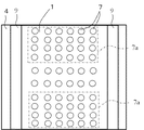
図1は、本形態の固体酸化物形燃料電池セル(以下、燃料電池セルと略す)の一例を示すものであり、(a)はその横断面図、(b)は(a)において、島状に複数形成された中間層が明確になるように、インターコネクタの記載を省略した側面図である。なお、両図面において、燃料電池セル10の各構成を一部拡大して示している。また、図1(b)は、長さ方向に縮小して記載しており、実際は上下方向に長い形状とされている。
FIG. 1 shows an example of a solid oxide fuel cell (hereinafter abbreviated as “fuel cell”) according to the present embodiment, in which (a) is a cross-sectional view and (b) is an island in FIG. It is the side view which abbreviate | omitted description of the interconnector so that the intermediate | middle layer formed in multiple numbers may become clear. In both drawings, each configuration of the
この燃料電池セル10は、中空平板型の燃料電池セル10で、断面が扁平状で、全体的に見て楕円柱状をした、NiとZrO2を除く無機酸化物とを含有する多孔質の導電性支持体1を備えている。導電性支持体1の内部には、適当な間隔で複数の燃料ガス流路2が長手方向に形成されており、燃料電池セル10は、この導電性支持体1上に各種の部材が設けられた構造を有している。
This
導電性支持体1は、図1に示されている形状から理解されるように、互いに平行な一対の平坦面nと、一対の平坦面nをそれぞれ接続する弧状面(側面)mとで構成されている。平坦面nの両面は互いにほぼ平行に形成されており、一方の平坦面n(下面)と両側の弧状面mを覆うように多孔質な燃料極層3が設けられており、さらに、この燃料極層3を覆うように、緻密質な固体電解質層4が積層されている。また、固体電解質層4の上には、反応防止層5を介して、燃料極層3と対面するように、多孔質な空気極層6が積層されている。
As understood from the shape shown in FIG. 1, the
燃料極層3、固体電解質層4、反応防止層5および空気極層6により発電部が構成されており、この発電部が導電性支持体1に設けられている。導電性支持体1は、内部に燃料ガスを流通させるための燃料ガス流路2を有するとともに、導電性支持体1は、固体電解質層4とインターコネクタ8とで気密に囲まれている。
The
燃料極層3および固体電解質層4は、両端の弧状面mを経由して他方の平坦面n(上面)まで形成されており、ZrO2系焼結体からなる固体電解質層4の両端部に、LaCrO3系焼結体からなるインターコネクタ8の両端部が焼結体からなる接合層9を介して接合され、固体電解質層4とインターコネクタ8で導電性支持体1を取り囲み、内部を流通する燃料ガスが外部に漏出しないように構成されている。
The
言い換えると、平面形状が矩形状のインターコネクタ8が導電性支持体1の上端から下端まで形成されており、その左右両側端部が、固体電解質層4の開口した両端部の表面に、接合層9を介して接合している。
In other words, the
また、燃料極層3および固体電解質層4が積層されていない他方の平坦面n(上面)には、複数の中間層7が所定間隔をおいて形成され、さらにLaを含有するインターコネクタ8が形成されており、複数の中間層7は、導電性支持体1とインターコネクタ8との間に島状に存在している。
A plurality of
複数の中間層7は円板状をなしており、図1(b)に示すように、セルの長さ方向に5個、横方向に6個行列をなして配列され、これらの複数の中間層7は相互に所定間隔をおいて形成されている。個数や配列については、自由に設定することができる。中間層7は、主面の形状が円状でなくても、例えば三角形、四角形等の多角形であってもよく、楕円形状であっても良い。
The plurality of
中間層7は、Zrを含有している。特に、Niと希土類元素が固溶したZrO2とを含有していることが望ましい。例えば、NiあるいはNiOの含有量は、65〜35体積%であるのが好ましい。さらに、これらの中間層7は緻密質であることが好ましく、その厚みは、7〜13μmであるのが好ましい。中間層7は、Niと希土類元素が固溶したZrO2とを含有するものであるが、その他に希土類元素酸化物、例えばY2O3を含有しても良い。
The
また、Niは必ずしも必要ではないが、導電性支持体1との接合強度を向上するため、Niを含有することが望ましい。さらに、Niの代わりに、もしくはNiとともにFe、Coを含有することもできる。中間層7とインターコネクタ8との間には、ランタンジル
コネート層が形成されている。
Ni is not always necessary, but it is desirable to contain Ni in order to improve the bonding strength with the
このような燃料電池セルでは、導電性支持体1とインターコネクタ8との間に、複数のNiと希土類元素が固溶したZrO2とを含有する中間層7が所定間隔をおいて形成されているため、中間層7と、この中間層7が接触するインターコネクタ8表面との間にはランタンジルコネートが生成し、中間層7とインターコネクタ8との接合強度を向上できる。
In such a fuel cell, an
一方、中間層7が形成されていない部分、すなわち、導電性支持体1の表面にインターコネクタ8が直接形成された部分は、導電性支持体1とインターコネクタ8との間に、電気抵抗の大きいランタンジルコネートが生成しないため、導電性支持体1とインターコネクタ8との間の導通を高く維持できる。
On the other hand, a portion where the
これにより、中間層7が形成されている部分では、導電性支持体1とインターコネクタ8との接合強度を向上でき、中間層7が形成されていない部分では、導電性支持体1とインターコネクタ8との間の電気抵抗を小さくして導通を向上できる。
Thereby, in the part in which the
中間層7は、インターコネクタ8側にドーム状に盛り上がった形状であることが望ましい。これにより、各素材間の熱膨張差に起因する応力を緩和することが可能となり、中間層を安定に形成することができる。
It is desirable that the
燃料電池セル10は、燃料極層3と空気極層6とが固体電解質層4を介して対面している部分が電極として機能して発電する。即ち、空気極層6の外側に空気等の酸素含有ガスを流し、且つ導電性支持体1内の燃料ガス流路2に燃料ガス(水素含有ガス)を流し、所定の作動温度まで加熱することにより発電する。そして、かかる発電によって生成した電流は、導電性支持体1に取り付けられているインターコネクタ8を介して集電される。
In the
以下に、本形態の燃料電池セル10を構成する各部材について説明する。
Below, each member which comprises the
導電性支持体1は、燃料ガスを燃料極層3まで透過させるためにガス透過性であること、インターコネクタ8を介して集電を行うために導電性であることが要求されることから、例えば、Niと、ZrO2を除く無機酸化物、例えば、特定の希土類酸化物とにより形成されることが好ましい。
ZrO2を除く無機酸化物としては、ZrO2以外であれば特に限定されるものではないが、下記のように熱膨張係数の観点、およびインターコネクタ8の構成元素と殆ど反応しないものである。
The
Examples of the inorganic oxide other than the ZrO 2, is not particularly limited as long as non-ZrO 2, in which hardly reacts viewpoint of thermal expansion coefficient, and the constituent elements of the
特定の希土類酸化物とは、導電性支持体1の熱膨張係数を固体電解質層4の熱膨張係数に近づけるために使用されるものであり、Y、Lu、Yb、Tm、Er、Ho、Dy、Gd、Sm、Prからなる群より選択される少なくとも1種の元素を含む希土類酸化物が、Niおよび/またはNiOとの組み合わせで使用することができる。このような希土類酸化物の具体例としては、Y2O3、Lu2O3、Yb2O3、Tm2O3、Er2O3、Ho2O3、Dy2O3、Gd2O3、Sm2O3、Pr2O3を例示することができ、Niおよび/またはNiOとの固溶、反応が殆どなく、また、熱膨張係数が固体電解質層4と同程度であり、かつ安価であるという点から、Y2O3、Yb2O3が好ましい。
The specific rare earth oxide is used to bring the thermal expansion coefficient of the
また、本形態においては、導電性支持体1の良好な導電率を維持し、かつ熱膨張係数を固体電解質層4と近似させるという点で、Niおよび/またはNiO:希土類酸化物=35:65〜65:35の体積比で存在することが好ましい。なお、導電性支持体1中には、要求される特性が損なわれない限りの範囲で、他の金属成分や酸化物成分を含有してい
てもよい。
In the present embodiment, Ni and / or NiO: rare earth oxide = 35: 65 in terms of maintaining good conductivity of the
また、導電性支持体1は、燃料ガス透過性を有していることが必要であるため、通常、開気孔率が30%以上、特に35〜50%の範囲にあることが好ましい。また、導電性支持体1の導電率は、300S/cm以上、特に440S/cm以上であることが好ましい。
Moreover, since the
なお、導電性支持体1の平坦面nの長さ(導電性支持体1の幅方向の長さ)は、通常、15〜35mm、弧状面mの長さ(弧の長さ)は、2〜8mmであり、導電性支持体1の厚み(平坦面n間の厚み)は1.5〜5mmであることが好ましい。導電性支持体1の長さは、100〜150mmとされている。
Note that the length of the flat surface n of the conductive support 1 (length in the width direction of the conductive support 1) is usually 15 to 35 mm, and the length of the arc-shaped surface m (arc length) is 2. The thickness of the conductive support 1 (thickness between the flat surfaces n) is preferably 1.5 to 5 mm. The length of the
燃料極層3は、電極反応を生じさせるものであり、それ自体公知の多孔質の導電性セラミックスにより形成することが好ましい。例えば、希土類元素が固溶したZrO2または希土類元素が固溶したCeO2と、Niおよび/またはNiOとから形成することができる。なお、希土類元素としては、導電性支持体1において例示した希土類元素を用いることができ、例えばYが固溶したZrO2(YSZ)とNiおよび/またはNiOとから形成することができる。
The
燃料極層3中の希土類元素が固溶したZrO2または希土類元素が固溶しているCeO2の含有量は、35〜65体積%の範囲にあるのが好ましく、またNiあるいはNiOの含有量は、65〜35体積%であるのが好ましい。さらに、この燃料極層3の開気孔率は、15%以上、特に20〜40%の範囲にあるのが好ましく、その厚みは、1〜30μmであるのが好ましい。
The content of ZrO 2 in which the rare earth element is dissolved in the
また、燃料極層3は、空気極層6に対面する位置に形成されていればよいため、例えば空気極層6が設けられている側の平坦面nにのみ燃料極層3が形成されていてもよい。すなわち、燃料極層3は平坦面nにのみ設けられ、固体電解質層4が燃料極層3上、導電性支持体1の両弧状面m上および燃料極層3が形成されていない他方の平坦面n上に形成された構造をしたものであってもよい。
Further, since the
固体電解質層4は、3〜15モル%のY、Sc、Yb等の希土類元素を含有した部分安定化あるいは安定化ZrO2からなる緻密質なセラミックスを用いるのが好ましい。また、希土類元素としては、安価であるという点からYが好ましい。さらに、固体電解質層4は、ガス透過を防止するという点から、相対密度(アルキメデス法による)が93%以上、特に95%以上の緻密質であることが望ましく、かつその厚みが5〜50μmであることが好ましい。
The
なお、固体電解質層4と後述する空気極層6との間に、固体電解質層4と空気極層6との接合を強固とするとともに、固体電解質層4の成分と空気極層6の成分とが反応して電気抵抗の高い反応層が形成されることを抑制する目的で反応防止層5を備えることもでき、図1に示した燃料電池セル10においては反応防止層5を備えた例を示している。
It should be noted that the
ここで、反応防止層5としては、CeとCe以外の他の希土類元素とを含有する組成にて形成することができ、例えば、(CeO2)1−x(REO1.5)x(式中、REはSm、Y、Yb、Gdの少なくとも1種であり、xは0<x≦0.3を満足する数)で表される組成を有していることが好ましい。さらには、電気抵抗を低減するという点から、REとしてSmやGdを用いることが好ましく、例えば10〜20モル%のSmO1.5またはGdO1.5が固溶したCeO2からなることが好ましい。 Here, the reaction preventing layer 5 can be formed with a composition containing Ce and another rare earth element other than Ce. For example, (CeO 2 ) 1-x (REO 1.5 ) x (formula Among these, RE is preferably at least one of Sm, Y, Yb, and Gd, and x preferably has a composition represented by 0 <x ≦ 0.3. Furthermore, from the viewpoint of reducing electrical resistance, it is preferable to use Sm or Gd as RE, for example, it is preferably made of CeO 2 in which 10 to 20 mol% of SmO 1.5 or GdO 1.5 is dissolved. .
空気極層6としては、いわゆるABO3型のペロブスカイト型酸化物からなる導電性セラミックスにより形成することが好ましい。かかるペロブスカイト型酸化物としては、遷移金属ペロブスカイト型酸化物、特にAサイトにSrとLaが共存するLaMnO3系酸化物、LaFeO3系酸化物、LaCoO3系酸化物の少なくとも1種が好ましく、600〜1000℃程度の作動温度での電気伝導性が高いという点からLaCoO3系酸化物が特に好ましい。なお、上記ペロブスカイト型酸化物においては、Bサイトに、CoとともにFeやMnが存在しても良い。
The
また、空気極層6は、ガス透過性を有する必要があり、従って、空気極層6を形成する導電性セラミックス(ペロブスカイト型酸化物)は、開気孔率が20%以上、特に30〜50%の範囲にあることが好ましい。さらに、空気極層6の厚みは、集電性という点から30〜100μmであることが好ましい。
Further, the
また、導電性支持体1の空気極層6側と反対側の平坦面n上には、中間層7を介してインターコネクタ8が積層されている。
An
インターコネクタ8としては、Laを含有するペロブスカイト型酸化物からなる導電性セラミックスにより形成されている。燃料ガス(水素含有ガス)および酸素含有ガスと接触するため、耐還元性、耐酸化性を有していることが必要である。このため、耐還元性、耐酸化性を有する導電性セラミックスとしては、例えば、Laと、CrまたはTiとを含有するペロブスカイト型酸化物(LaCrO3系酸化物、LaTiO3系酸化物)を用いることができる。導電性支持体1および固体電解質層4の熱膨張係数に近づける目的から、BサイトにMgが存在するLaCrMgO3系酸化物を用いることができる。
The
また、インターコネクタ8の厚みは、ガスのリーク防止と電気抵抗という点から、10〜50μmであることが好ましい。この範囲ならばガスのリークを防止できるとともに、電気抵抗を小さくできる。
The thickness of the
上記した固体電解質層4の両端部には、インターコネクタ8の両端部が接合層9を介して接合されている。
Both end portions of the
以上説明した本形態の燃料電池セル10の作製方法の一例について説明する。
An example of a method for manufacturing the
先ず、例えば、Niおよび/またはNiO粉末と、Y2O3などの希土類酸化物の粉末と、有機バインダーと、溶媒とを混合して坏土を調製し、この坏土を用いて押出成形により導電性支持体成形体を作製し、これを乾燥する。なお、導電性支持体成形体として、導電性支持体成形体を900〜1000℃にて2〜6時間仮焼した仮焼体を用いてもよい。 First, for example, Ni and / or NiO powder, a rare earth oxide powder such as Y 2 O 3 , an organic binder, and a solvent are mixed to prepare a clay, and this clay is used for extrusion molding. A conductive support molded body is prepared and dried. In addition, as the conductive support molded body, a calcined body obtained by calcining the conductive support molded body at 900 to 1000 ° C. for 2 to 6 hours may be used.
次に、例えば所定の調合組成に従いNiO、Y2O3が固溶したZrO2(YSZ)の素原料を秤量、混合する。この後、混合した粉体に、有機バインダーおよび溶媒を混合して燃料極層用スラリーを調製する。 Next, the raw material of ZrO 2 (YSZ) in which NiO and Y 2 O 3 are dissolved, for example, is weighed and mixed according to a predetermined composition. Thereafter, an organic binder and a solvent are mixed with the mixed powder to prepare a slurry for the fuel electrode layer.
さらに、希土類元素が固溶したZrO2粉末に、トルエン、バインダー、市販の分散剤等を加えてスラリー化したものをドクターブレード等の方法により、7〜75μmの厚さに成形してシート状の固体電解質層成形体を作製する。得られたシート状の固体電解質層成形体上に燃料極層用スラリーを塗布して燃料極層成形体を形成し、この燃料極層成形体側の面を導電性支持体成形体に積層する。なお、燃料極層用スラリーを導電性支持体成形体の所定位置に塗布し乾燥して、固体電解質層成形体を導電性支持体成形体(燃料極層成形体)に積層しても良い。 Further, a slurry obtained by adding toluene, a binder, a commercially available dispersant, etc. to a ZrO 2 powder in which a rare earth element is solid-solubilized is molded to a thickness of 7 to 75 μm by a method such as a doctor blade. A solid electrolyte layer molded body is produced. The fuel electrode layer slurry is applied on the obtained sheet-shaped solid electrolyte layer molded body to form a fuel electrode layer molded body, and the surface on the fuel electrode layer molded body side is laminated on the conductive support molded body. The slurry for the fuel electrode layer may be applied to a predetermined position of the conductive support molded body and dried, and the solid electrolyte layer molded body may be laminated on the conductive support molded body (fuel electrode layer molded body).
続いて固体電解質層4と空気極層6との間に配置する反応防止層5を形成する。
Subsequently, a reaction preventing layer 5 disposed between the
例えば、GdO1.5が固溶したCeO2粉末を800〜900℃にて2〜6時間、熱処理を行い、反応防止層成形体用の原料粉末を調整する。 For example, CeO 2 powder in which GdO 1.5 is dissolved is heat-treated at 800 to 900 ° C. for 2 to 6 hours to prepare a raw material powder for a reaction preventing layer molded body.
そして、反応防止層成形体の原料粉末に、溶媒としてトルエンを添加し、中間層用スラリーを作製し、このスラリーを固体電解質層成形体上に塗布して反応防止層の塗布膜を形成し、成形体を作製する。なお、シート状の成形体を作製し、これを固体電解質層成形体上に積層してもよい。 Then, toluene is added as a solvent to the raw material powder of the reaction prevention layer molded body to produce a slurry for the intermediate layer, and this slurry is applied onto the solid electrolyte layer molded body to form a coating film of the reaction prevention layer, A molded body is produced. In addition, a sheet-like molded body may be produced and laminated on the solid electrolyte layer molded body.
続いて、インターコネクタ用材料(例えば、LaCrMgO3系酸化物粉末)、有機バインダー及び溶媒を混合してスラリーを調製し、インターコネクタ用シートを作製する。 Subsequently, a material for an interconnector (for example, LaCrMgO 3 oxide powder), an organic binder, and a solvent are mixed to prepare a slurry, and an interconnector sheet is prepared.
続いて、導電性支持体1とインターコネクタ8との間に位置する中間層成形体を形成する。例えば、Yが固溶したZrO2とNiOが体積比で40:60〜60:40の範囲となるように混合して乾燥し、有機バインダー等を加えて中間層用スラリーを調整し、導電性支持体成形体に塗布して中間層成形体を形成する。中間層は多数の島状に形成されているため、中間層成形体を複数の島状に形成するため、例えばスクリーン印刷により、図1(b)に示すように行列をなして形成する。
Subsequently, an intermediate layer molded body positioned between the
この後、例えば、MgOを50〜68モル%と、Y2O3を30〜47モル%と、La2O3を3〜5モル%とからなる接合層形成材料、有機バインダー及び溶媒を混合してスラリーを調製し、このスラリーを、固体電解質層成形体の両端部に塗布して接合層成形体を作製し、この接合層成形体の上に、インターコネクタ用シートの端部を積層するように、かつ、中間層成形体が形成された導電性支持体成形体上に積層し、積層成形体を作製する。 Thereafter, for example, a bonding layer forming material composed of 50 to 68 mol% of MgO, 30 to 47 mol% of Y 2 O 3, and 3 to 5 mol% of La 2 O 3 , an organic binder and a solvent are mixed. A slurry is prepared, and this slurry is applied to both ends of the solid electrolyte layer molded body to produce a bonded layer molded body, and the end of the interconnector sheet is laminated on the bonded layer molded body. In the same manner, the laminated molded body is produced by laminating on the conductive support molded body on which the intermediate layer molded body is formed.
次いで、上記の積層成形体を脱バインダー処理し、酸素含有雰囲気中、1400〜1450℃にて2〜6時間、同時焼結(同時焼成)する。 Next, the above-mentioned laminated molded body is subjected to binder removal treatment, and is simultaneously sintered (simultaneously fired) in an oxygen-containing atmosphere at 1400 to 1450 ° C. for 2 to 6 hours.
さらに、空気極層用材料(例えば、LaCoO3系酸化物粉末)、溶媒および増孔剤を含有するスラリーをディッピング等により反応防止層上に塗布し、1000〜1300℃で、2〜6時間焼き付けることにより、図1に示す構造の本形態の燃料電池セル10を製造できる。なお、燃料電池セル10は、その後、内部に水素ガスを流し、導電性支持体1および燃料極層3の還元処理を行なうのが好ましい。その際、たとえば750〜1000℃にて5〜20時間還元処理を行なうのが好ましい。
Further, a slurry containing an air electrode layer material (for example, LaCoO 3 oxide powder), a solvent and a pore-forming agent is applied on the reaction preventing layer by dipping or the like, and baked at 1000 to 1300 ° C. for 2 to 6 hours. Thereby, the
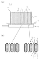
図3は、上述した燃料電池セル10の複数個を、集電部材13を介して電気的に直列に接続して構成される燃料電池セルスタック装置の一例を示したものであり、(a)は燃料電池セルスタック装置11を概略的に示す側面図、(b)は(a)の燃料電池セルスタック装置11の一部拡大断面図であり、(a)で示した破線で囲った部分を抜粋して示している。なお、(b)において(a)で示した破線で囲った部分に対応する部分を明確とするために矢印にて示しており、(b)で示す燃料電池セル10においては、上述した中間層7、反応防止層5等の一部の部材を省略して示している。
FIG. 3 shows an example of a fuel cell stack device configured by electrically connecting a plurality of the above-described
なお、燃料電池セルスタック装置11においては、各燃料電池セル10を集電部材13を介して配列することで燃料電池セルスタック12を構成しており、各燃料電池セル10の下端部が、燃料電池セル10に燃料ガスを供給するためのガスタンク16に、ガラスシール材等の接着剤により固定されている。また、燃料電池セル10の配列方向の両端から集電部材13を介して燃料電池セルスタック12を挟持するように、ガスタンク16に下
端部が固定された弾性変形可能な導電部材14を具備している。
In the fuel
また、図3に示す導電部材14においては、燃料電池セル10の配列方向に沿って外側に向けて延びた形状で、燃料電池セルスタック12(燃料電池セル10)の発電により生じる電流を引出すための電流引出し部15が設けられている。
Further, in the
ここで、本形態の燃料電池セルスタック装置11においては、上述した燃料電池セル10を用いて、燃料電池セルスタック12を構成することにより、長期信頼性が向上した燃料電池セルスタック装置11とすることができる。
Here, in the fuel
図3に示す燃料電池セルスタック装置11では、燃料電池セル10の下端部は、燃料電池セル10に燃料ガスを供給するためのガスタンク16に、ガラスシール材等の接着剤により固定されており、接着剤と燃料電池セル10のインターコネクタ層8とは膨張係数が異なるため、また、固定部においてはインターコネクタ層8に応力が作用しやすいため、また、燃料電池セル10の上端部では燃料ガスが燃焼して高温となるため、導電性支持体1とインターコネクタ層8との間に強い接合強度が要求されている。
In the fuel
そこで、図2に示すように、中間層7を、導電性支持体1の長さ方向(図2の上下方向)の両端部に、導電性支持体1の長さ方向中央部よりも高い密度で形成されていることが望ましい。このように、導電性支持体1の長さ方向の両端部における中間層7の形成密度を高くすることにより、導電性支持体1の長さ方向の両端部おいて、導電性支持体1とインターコネクタ層8との間における接合強度を向上できる。
Therefore, as shown in FIG. 2, the
一方で、燃料電極層3と固体電解質層4と空気極層6とが積層された発電部は、導電性支持体1の長さ方向の中央部に形成されており、両端部には形成されていないため、導電性支持体1の長さ方向中央部では中間層7の形成密度が低いことに起因して導電性支持体1とインターコネクタ層6との電気伝導性を高くでき、発電性能を向上できる。
On the other hand, the power generation unit in which the
すなわち、導電性支持体1の長さ方向の両端部には、長さ方向中央部よりも、複数の中間層7を高い形成密度(導電性支持体1の一定面積に対する複数の中間層の面積)で形成した高密度形成部7aを有している。これらの高密度形成部7aの領域(面積)については適宜設定することができ、その形成密度についても適宜設定することができる。
That is, at both ends in the length direction of the
1個の中間層の大きさは、例えば、円板状の場合には、主面の寸法が1mm以上であることが望ましいが、導電性支持体1とインターコネクタ層6との接合強度を向上するためには、小さい、例えば直径5mm以下であることが望ましい。
As for the size of one intermediate layer, for example, in the case of a disk shape, the size of the main surface is preferably 1 mm or more, but the bonding strength between the
また、図2では、導電性支持体1の長さ方向の両端部に高密度形成部7aを形成したが、上端部、または下端部のいずれかに形成しても良いことは勿論である。
In FIG. 2, the high
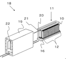
図4は、燃料電池セルスタック装置11を収納容器内に収納してなる燃料電池モジュール18の一例を示す外観斜視図であり、直方体状の収納容器19の内部に、図3に示した燃料電池セルスタック装置11を収納して構成されている。
FIG. 4 is an external perspective view showing an example of the
なお、燃料電池セル10にて使用する燃料ガスを得るために、天然ガスや灯油等の原燃料を改質して燃料ガスを生成するための改質器20を燃料電池セルスタック12の上方に配置している。そして、改質器20で生成された燃料ガスは、ガス流通管21を介してガスタンク16に供給され、ガスタンク16を介して燃料電池セル10の内部に設けられたガス流路2に供給される。
Note that a
なお、図4においては、収納容器19の一部(前後面)を取り外し、内部に収納されている燃料電池セルスタック装置11および改質器20を後方に取り出した状態を示している。図4に示した燃料電池モジュール18においては、燃料電池セルスタック装置11を、収納容器19内にスライドして収納することが可能である。なお、燃料電池セルスタック装置11は、改質器20を含むものとしても良い。
FIG. 4 shows a state in which a part (front and rear surfaces) of the
また収納容器19の内部に設けられた酸素含有ガス導入部材22は、図4においてはガスタンク16に並置された燃料電池セルスタック12の間に配置されるとともに、酸素含有ガスが燃料ガスの流れに合わせて、燃料電池セル10の側方を下端部から上端部に向けて流れるように、燃料電池セル10の下端部に酸素含有ガスを供給する。
Further, in FIG. 4, the oxygen-containing
そして、燃料電池セル10のガス流路より排出される燃料ガスを酸素含有ガスと反応させて燃料電池セル10の上端部側で燃焼させることにより、燃料電池セル10の温度を上昇させることができ、燃料電池セルスタック装置11の起動を早めることができる。また、燃料電池セル10の上端部側にて、燃料電池セル10のガス流路から排出される燃料ガスと酸素含有ガスとを燃焼させることにより、燃料電池セル10(燃料電池セルスタック12)の上方に配置された改質器20を温めることができる。それにより、改質器20で効率よく改質反応を行うことができる。
Then, the temperature of the
さらに、本形態の燃料電池モジュール18においても、上述した燃料電池セルスタック装置11を収納容器19内に収納してなることから、長期信頼性が向上した燃料電池モジュール18とすることができる。
Furthermore, in the
図5は、外装ケース内に図4で示した燃料電池モジュール18と、燃料電池セルスタック装置11を動作させるための補機とを収納してなる燃料電池装置を示す斜視図である。なお、図5においては一部構成を省略して示している。
FIG. 5 is a perspective view showing a fuel cell device in which the
図5に示す燃料電池装置23は、支柱24と外装板25とから構成される外装ケース内を仕切板26により上下に区画し、その上方側を上述した燃料電池モジュール18を収納するモジュール収納室27とし、下方側を燃料電池モジュール18を動作させるための補機類を収納する補機収納室28として構成されている。なお、補機収納室28に収納する補機類は省略して示している。
The
また、仕切板26には、補機収納室28の空気をモジュール収納室27側に流すための空気流通口29が設けられており、モジュール収納室27を構成する外装板25の一部に、モジュール収納室27内の空気を排気するための排気口30が設けられている。
In addition, the
このような燃料電池装置23においては、上述したように、信頼性を向上することができる燃料電池モジュール18をモジュール収納室27に収納して構成されることにより、信頼性の向上した燃料電池装置23とすることができる。
In such a
以上、本発明は上述の実施の形態に限定されるものではなく、本発明の要旨を逸脱しない範囲内において、種々の変更、改良等が可能である。 As mentioned above, this invention is not limited to the above-mentioned embodiment, A various change, improvement, etc. are possible in the range which does not deviate from the summary of this invention.
例えば、上記形態では、中空平板型の固体電解質形燃料電池セルについて説明したが、円筒型の固体電解質形燃料電池セルであっても良いことは勿論である。 For example, in the above embodiment, the hollow plate type solid oxide fuel cell has been described, but it is needless to say that it may be a cylindrical solid electrolyte fuel cell.
1:導電性支持体
2:燃料ガス流路
3:燃料極層
4:固体電解質層
5:反応防止層
6:空気極層
7:中間層
8:インターコネクタ
11:燃料電池セルスタック装置
18:燃料電池モジュール
1: Conductive support 2: Fuel gas flow path 3: Fuel electrode layer 4: Solid electrolyte layer 5: Reaction prevention layer 6: Air electrode layer 7: Intermediate layer 8: Interconnector 11: Fuel cell stack device 18: Fuel Battery module
Claims (4)
Priority Applications (1)
| Application Number | Priority Date | Filing Date | Title |
|---|---|---|---|
| JP2011042089A JP2012181927A (en) | 2011-02-28 | 2011-02-28 | Solid oxide fuel cell and fuel cell module |
Applications Claiming Priority (1)
| Application Number | Priority Date | Filing Date | Title |
|---|---|---|---|
| JP2011042089A JP2012181927A (en) | 2011-02-28 | 2011-02-28 | Solid oxide fuel cell and fuel cell module |
Publications (1)
| Publication Number | Publication Date |
|---|---|
| JP2012181927A true JP2012181927A (en) | 2012-09-20 |
Family
ID=47012980
Family Applications (1)
| Application Number | Title | Priority Date | Filing Date |
|---|---|---|---|
| JP2011042089A Withdrawn JP2012181927A (en) | 2011-02-28 | 2011-02-28 | Solid oxide fuel cell and fuel cell module |
Country Status (1)
| Country | Link |
|---|---|
| JP (1) | JP2012181927A (en) |
Cited By (4)
| Publication number | Priority date | Publication date | Assignee | Title |
|---|---|---|---|---|
| JP2013157190A (en) * | 2012-01-30 | 2013-08-15 | Kyocera Corp | Solid oxide fuel cell, cell stack device, fuel cell module, and fuel cell device |
| CN105874103A (en) * | 2014-01-29 | 2016-08-17 | 京瓷株式会社 | Cell, cell stack device, module and module-containing device |
| RU2597873C1 (en) * | 2015-06-24 | 2016-09-20 | Общество с ограниченной ответственностью "Завод электрохимических преобразователей" (ООО "ЗЭП") | Battery of solid oxide fuel cells |
| WO2017033822A1 (en) * | 2015-08-22 | 2017-03-02 | 京セラ株式会社 | Cell, cell stack device, module, and module accommodation device |
-
2011
- 2011-02-28 JP JP2011042089A patent/JP2012181927A/en not_active Withdrawn
Cited By (8)
| Publication number | Priority date | Publication date | Assignee | Title |
|---|---|---|---|---|
| JP2013157190A (en) * | 2012-01-30 | 2013-08-15 | Kyocera Corp | Solid oxide fuel cell, cell stack device, fuel cell module, and fuel cell device |
| CN105874103A (en) * | 2014-01-29 | 2016-08-17 | 京瓷株式会社 | Cell, cell stack device, module and module-containing device |
| US20160351935A1 (en) * | 2014-01-29 | 2016-12-01 | Kyocera Corporation | Cell, cell stack device, module and module-containing device |
| EP3101720A4 (en) * | 2014-01-29 | 2017-07-12 | Kyocera Corporation | Cell, cell stack device, module and module-containing device |
| US10938051B2 (en) | 2014-01-29 | 2021-03-02 | Kyocera Corporation | Cell, cell stack device, module and module-containing device |
| RU2597873C1 (en) * | 2015-06-24 | 2016-09-20 | Общество с ограниченной ответственностью "Завод электрохимических преобразователей" (ООО "ЗЭП") | Battery of solid oxide fuel cells |
| WO2017033822A1 (en) * | 2015-08-22 | 2017-03-02 | 京セラ株式会社 | Cell, cell stack device, module, and module accommodation device |
| JP6151876B1 (en) * | 2015-08-22 | 2017-06-21 | 京セラ株式会社 | Cell, cell stack device, module, and module storage device |
Similar Documents
| Publication | Publication Date | Title |
|---|---|---|
| JP5952139B2 (en) | Cell stack device, fuel cell module and fuel cell device | |
| JP6208499B2 (en) | Fuel cell or electrolysis cell, cell stack device, module and module storage device | |
| JP6105824B1 (en) | Cell stack device, module and module housing device | |
| JP2013012397A (en) | Solid oxide fuel cell and fuel cell module | |
| JP5934446B2 (en) | Cell, cell stack device and module, and module housing device | |
| JP5645712B2 (en) | Solid oxide fuel cell and fuel cell module | |
| KR20160012217A (en) | Cell, cell stacker, module, and module storage device | |
| JP5377271B2 (en) | Cell stack device, fuel cell module and fuel cell device | |
| JP5377599B2 (en) | FUEL BATTERY CELL, CELL STACK DEVICE USING THE SAME, FUEL CELL MODULE, AND FUEL CELL DEVICE | |
| JP5738075B2 (en) | Solid oxide fuel cell | |
| JP5574891B2 (en) | Solid oxide fuel cell | |
| JP5328317B2 (en) | Fuel cell, fuel cell stack device, fuel cell module and fuel cell device | |
| JP2012181927A (en) | Solid oxide fuel cell and fuel cell module | |
| JP5726023B2 (en) | Solid oxide fuel cell, cell stack device, fuel cell module and fuel cell device | |
| JP6158683B2 (en) | Cell stack device, module and module storage device | |
| JP2015082389A (en) | Cell, cell stack device, module, and module storing device | |
| JP6166151B2 (en) | Cell, cell stack device, module, and module storage device | |
| JP2013157190A (en) | Solid oxide fuel cell, cell stack device, fuel cell module, and fuel cell device | |
| JP2012178257A (en) | Porous conductive substrate for fuel cell, and solid oxide fuel cell | |
| JP5328316B2 (en) | Fuel cell, fuel cell stack device, fuel cell module and fuel cell device | |
| JP6215727B2 (en) | Cell, cell stack device, module, and module housing device | |
| JP2012114033A (en) | Support medium for fuel battery, fuel battery cell, fuel battery cell device, fuel battery module, and fuel battery device | |
| JP5769661B2 (en) | Solid oxide fuel cell, fuel cell module and fuel cell device | |
| JP5705697B2 (en) | Solid oxide fuel cell and fuel cell module | |
| JP5818656B2 (en) | Solid oxide fuel cell, cell stack device, fuel cell module and fuel cell device |
Legal Events
| Date | Code | Title | Description |
|---|---|---|---|
| A300 | Withdrawal of application because of no request for examination |
Free format text: JAPANESE INTERMEDIATE CODE: A300 Effective date: 20140513 |