JP2012181414A - Image forming apparatus - Google Patents
Image forming apparatus Download PDFInfo
- Publication number
- JP2012181414A JP2012181414A JP2011044990A JP2011044990A JP2012181414A JP 2012181414 A JP2012181414 A JP 2012181414A JP 2011044990 A JP2011044990 A JP 2011044990A JP 2011044990 A JP2011044990 A JP 2011044990A JP 2012181414 A JP2012181414 A JP 2012181414A
- Authority
- JP
- Japan
- Prior art keywords
- image
- toner
- detection
- portion output
- output
- Prior art date
- Legal status (The legal status is an assumption and is not a legal conclusion. Google has not performed a legal analysis and makes no representation as to the accuracy of the status listed.)
- Pending
Links
Images


Abstract
Description
本発明は、電子写真方式の複写機、ファクシミリ、プリンタ、複合機等の画像形成装置に関するものである。 The present invention relates to an image forming apparatus such as an electrophotographic copying machine, a facsimile, a printer, and a multifunction machine.
従来、電子写真方式の画像形成装置において、画像濃度を安定化するために、像担持体上に形成したトナーパターンのトナー付着量を光学的検知手段により検出する。そして、光学的検知手段により検出した検出結果に基づき帯電バイアス、現像バイアス、露光手段の露光量等の作像条件を制御するプロセスコントロールを行なう画像形成装置が知られている。 2. Description of the Related Art Conventionally, in an electrophotographic image forming apparatus, in order to stabilize the image density, the toner adhesion amount of a toner pattern formed on an image carrier is detected by an optical detection means. An image forming apparatus that performs process control for controlling image forming conditions such as a charging bias, a developing bias, and an exposure amount of an exposure unit based on a detection result detected by an optical detection unit is known.
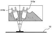
トナーパターンの光学的検知手段としては、発光素子(発光手段)としてのLEDと、受光素子(受光手段)としてのPD(フォトダイオード)またはPTr(フォトトランジスタ)とを組み合わせた反射型センサが広く用いられている。反射型センサの構成としては、図3に示す、発光素子であるLED310aから照射し、正反射光のみを受光素子310bで受光するタイプの反射型センサ。図4に示す、発光素子であるLED310aから照射し、拡散反射光のみを受光素子310cで受光するタイプの反射型センサ。そして、図5に示す、発光素子であるLED310aから照射し、正反射光のみを受光する受光素子310bと、拡散反射光のみを受光する受光素子310cとを備え、正反射光と拡散反射光の両者を検出するタイプの反射型センサ。これらのような3つのタイプの反射型センサが従来から知られている。
As an optical detection means for a toner pattern, a reflective sensor in which an LED as a light emitting element (light emitting means) and a PD (photodiode) or PTr (phototransistor) as a light receiving element (light receiving means) are widely used. It has been. As a configuration of the reflective sensor, a reflective sensor of the type shown in FIG. 3 that irradiates from the
このような反射型センサを用いる画像形成装置では、発光素子により像持体上に作像された所定のトナーパターンに光照射を行い、受光素子によりトナーパターンからの正反射光または拡散反射光を検知している。そして、得られたセンサ出力(受光光量)をトナー付着量に変換している。しかしながら、センサ出力は、反射型センサ自体の経時変動や、トナーパターンが形成される像担持体の地肌部の影響等により誤差を含んでしまう場合があり、トナー付着量の検知誤差が生じることがある。そこで、正確なトナー付着量を得るため、反射型センサの発光素子の調整を行ったり、地肌部の影響を受けたパターン部のパターン部出力Vspや、パターン部出力Vspから導出した値を補正したりしてトナー付着量に変換している。また、トナー付着量への変換は、予め実験的に求められたトナー付着量と、補正後のパターン部出力Vsp又は補正後のパターン部出力Vspから導出した値との関係式に基づきトナー付着量を算出する方法が一般的である。 In an image forming apparatus using such a reflective sensor, light is emitted to a predetermined toner pattern formed on the image carrier by a light emitting element, and regular reflection light or diffuse reflection light from the toner pattern is emitted by the light receiving element. Detected. The obtained sensor output (the amount of received light) is converted into the toner adhesion amount. However, the sensor output may include an error due to the temporal change of the reflective sensor itself, the influence of the background portion of the image carrier on which the toner pattern is formed, and the like, and an error in detecting the toner adhesion amount may occur. is there. Therefore, in order to obtain an accurate toner adhesion amount, the light emitting element of the reflective sensor is adjusted, or the pattern portion output Vsp of the pattern portion affected by the background portion or the value derived from the pattern portion output Vsp is corrected. Or converted into toner adhesion. Further, the conversion to the toner adhesion amount is performed based on a relational expression between the toner adhesion amount experimentally obtained in advance and the corrected pattern portion output Vsp or a value derived from the corrected pattern portion output Vsp. The method of calculating is generally.
発光素子の発光光量の調整にはいくつかの種類がある。発光素子から光の一部をビームスプリッタなどで分離し、分離した光を一定に保つように調整する方法。反射型センサ内部に白色基準板を持ち、白色基準板から反射した拡散反射光を一定に保つように調整する方法。調整用に特別な部材を用いずに、発光素子から出射した光を像担持体の地肌部で反射させ、受光素子で受光した光を一定に保つように調整する方法等がある。 There are several types of adjustment of the light emission amount of the light emitting element. A method in which a part of light is separated from the light emitting element by a beam splitter or the like and adjusted so that the separated light is kept constant. A method in which a white reference plate is provided inside the reflective sensor, and the diffuse reflection light reflected from the white reference plate is kept constant. There is a method of adjusting the light emitted from the light emitting element to reflect on the background portion of the image carrier and keeping the light received by the light receiving element constant without using a special member for adjustment.
像担持体の地肌部の影響は、地肌部からの反射光を受光した受光素子の地肌部出力Vsgの変動として表れる。そして、地肌部出力Vsgの変動は、主に、像担持体の地肌部と反射型センサとの空間的な位置関係や、像担持体の地肌部の光沢度等の表面の光学特性が変化することで生じる。そして、像担持体は円筒状やベルト状のものであり、これらを回転させて使用するのが一般的であるので、地肌部出力Vsgの変動は周期性を持っている。 The influence of the background portion of the image carrier appears as a change in the background portion output Vsg of the light receiving element that receives the reflected light from the background portion. The fluctuation of the background portion output Vsg mainly changes the spatial positional relationship between the background portion of the image carrier and the reflective sensor and the surface optical characteristics such as the glossiness of the background portion of the image carrier. It happens by that. The image carrier is in the form of a cylinder or a belt, and these are generally used after being rotated. Therefore, the fluctuation of the background portion output Vsg has periodicity.
例えば、特許文献1に記載された構成では、反射型センサを、回転可能に支持された中間転写ベルトの架張ローラの1つに中間転写ベルトを介して対向させて固定的に設けている。また、正反射光を、反射型センサに設けたビームスプリッタで反射光の入射面に平行な偏光方向を有するP偏光と、垂直な偏光方向を有するS偏光に分割し、分割したP偏光とS偏光を、それぞれ受光する2つの受光素子を設けている。この分割したP偏光を受光した受光素子のP偏光量信号SigPと、S偏光を受光した受光素子のS偏光量信号SigSとの比である光量信号比をトナー付着量の指標としている。そして、中間転写ベルト上のトナー付着量の検知に先立ち予め、地肌部の光量信号比の架張ローラにおける偏心成分と、地肌部の光量信号比の中間転写ベルトにおける周期プロファイルとを求めて記憶している。その後、中間転写ベルト上のトナー付着量を求めるべくセンサの検知出力の変換を行う際に、センサ出力からパターン部の光量信号比を算出した後、上記偏心成分及び周期プロファイルを用いて、パターン部の光量信号比を補正(距離変動補正)している。 For example, in the configuration described in Patent Document 1, the reflective sensor is fixedly provided so as to face one of the stretching rollers of the intermediate transfer belt that is rotatably supported via the intermediate transfer belt. Further, the regular reflected light is divided into P-polarized light having a polarization direction parallel to the incident surface of the reflected light and S-polarized light having a perpendicular polarization direction by a beam splitter provided in the reflection type sensor, and the divided P-polarized light and S Two light receiving elements for receiving polarized light are provided. A light amount signal ratio that is a ratio of the P polarization amount signal SigP of the light receiving element that receives the divided P polarized light and the S polarization amount signal SigS of the light receiving element that receives the S polarized light is used as an index of the toner adhesion amount. Prior to detection of the toner adhesion amount on the intermediate transfer belt, the eccentric component of the tension roller of the light amount signal ratio of the background portion and the periodic profile of the intermediate transfer belt of the light amount signal ratio of the background portion are obtained and stored. ing. Thereafter, when converting the detection output of the sensor to obtain the toner adhesion amount on the intermediate transfer belt, after calculating the light amount signal ratio of the pattern portion from the sensor output, the pattern portion is obtained using the eccentric component and the periodic profile. Is corrected (distance variation correction).
また、特許文献2には、中間転写ベルトの交換による地肌部出力Vsg変動の周期性の変化や、中間転写ベルトの光沢度の変化、光学センサの検知面の汚れ等の経時的な地肌部出力Vsg変動の周期性の変化に対応するための構成が記載されている。具体的には、所定のタイミングで中間転写ベルト1周分の地肌部出力Vsgを所定の間隔で測定しなおして記憶領域に保存する。そして、特許文献2に記載された構成での補正方法は、次の式(1)により行なわれる。
Vspx(Vcx)=Vx−△Vsgx ・・・ (1)
ここで、Vspx(Vcx)は検知位置xでの補正後のパターン部出力、Vxは検知位置xでの補正前のパターン部出力、△Vsgxは検知位置xで測定した地肌部出力Vsgの変動量を示している。
Further,
Vspx (Vcx) = Vx−ΔVsgx (1)
Here, Vspx (Vcx) is the pattern portion output after correction at the detection position x, Vx is the pattern portion output before correction at the detection position x, and ΔVsgx is the fluctuation amount of the background portion output Vsg measured at the detection position x. Is shown.
しかしながら、特許文献2に記載された構成では、パターン部出力Vspを地肌部出力Vsgに応じて補正を行う場合に問題があることがわかった。パターン部出力Vspは、地肌部出力Vsgが変動した分だけ変動するのではなく、パターン部でのトナー付着量に応じて、地肌部出力Vsgの変動に対するパターン部出力Vspの変動幅に違いが生じる。そして、トナー付着量を検知する際に、パターン部でのトナー付着量に応じて、地肌部出力Vsgの変動に対するパターン部出力Vspの変動幅に違いが生じることに起因したトナー付着量の検知誤差が生じることとなる。
However, in the configuration described in
パターン部出力Vspは、中間転写ベルト上に少量のトナーが付着している(トナー付着量が少ない)場合、中間転写ベルト表面の露出面積が大きいので、地肌部出力Vsg変動の影響を大きく受ける。しかし、トナーで覆いつくされている(トナー付着量が多い)場合には、パターン部出力Vspは地肌部出力Vsgの影響をほとんど受けない。 The pattern portion output Vsp is greatly affected by the fluctuation of the background portion output Vsg because the exposed area of the surface of the intermediate transfer belt is large when a small amount of toner adheres to the intermediate transfer belt (the toner adhesion amount is small). However, when covered with toner (toner adhesion amount is large), the pattern portion output Vsp is hardly affected by the background portion output Vsg.
具体的には、特許文献2の構成では、パターン部出力Vspの補正は、地肌部出力Vsgが変動した分だけパターン部出力Vspが変動するとの考えに基づいた上記式(1)により行うため、パターン部のトナー付着量に応じた補正はできない。そして、パターン部へのトナー付着量が大きい場合には補正過多となってしまう。したがって、パターン部でのトナー付着量に応じて、地肌部出力Vsgの変動に対するパターン部出力Vspの変動幅に違いが生じることに起因したトナー付着量の検知誤差を、低減できない。
Specifically, in the configuration of
また、この補正についての問題に関して、特許文献1の構成では、パターン部の光量信号比の補正方法に対して詳しい記述がなく、「周期プロファイルと偏心成分を合成し、光量信号比の補正を行う」という記述のみであり、その補正方法の開示もない。補正方法の開示がないため、パターン部でのトナー付着量に応じて、地肌部の光量信号比の変動に対するパターン部の光量信号比の変動幅に違いが生じることに起因したトナー付着量の検知誤差を、低減できているか否か不明である。仮に、トナー付着量に応じた補正を実施するとしても、記憶している情報が地肌部の光量信号比の架張ローラにおける偏心成分と、地肌部の光量信号比の中間転写ベルトにおける周期プロファイルとであるため、トナー付着量に応じた補正が非常に複雑になるものと思われる。 Regarding the problem regarding this correction, in the configuration of Patent Document 1, there is no detailed description of the correction method of the light amount signal ratio of the pattern portion, and “the light intensity signal ratio is corrected by synthesizing the periodic profile and the eccentric component. ", And no correction method is disclosed. Since there is no disclosure of the correction method, depending on the amount of toner attached to the pattern portion, detection of the amount of toner attached due to the difference in the fluctuation range of the light amount signal ratio of the pattern portion with respect to the variation of the light amount signal ratio of the background portion It is unknown whether the error can be reduced. Even if correction according to the toner adhesion amount is performed, the stored information includes an eccentric component in the stretching roller of the light amount signal ratio of the background portion, and a periodic profile in the intermediate transfer belt of the light amount signal ratio of the background portion. Therefore, it seems that the correction according to the toner adhesion amount becomes very complicated.
また、特許文献1に記載の構成では、パターン部の光量信号比を検知する中間転写ベルト上の箇所と同一の箇所で、パターン部の光量信号比を検知する前に、地肌部の光量信号比を検知している。そして、この中間転写ベルト上の箇所がクリーニング装置を通過した後に、この箇所に1次転写部でパターン部を形成して、パターン部の光量信号比を検知している。このため、パターン部の光量信号比を検知する中間転写ベルト上の箇所において、中間転写ベルトの光沢度等の表面の光学特性に不規則な変化が、クリーニング装置を通過する前後で生じるという問題がある。そして、地肌部出力の検知とパターン部出力の検知とで、地肌部の表面の光学特性が異なることに起因したトナー付着量の検知誤差が生じることとなる。次に、このような問題が生じる理由を説明する。 In the configuration described in Patent Document 1, the light amount signal ratio of the background portion is detected before detecting the light amount signal ratio of the pattern portion at the same position on the intermediate transfer belt that detects the light amount signal ratio of the pattern portion. Is detected. Then, after a location on the intermediate transfer belt passes through the cleaning device, a pattern portion is formed at this location by the primary transfer portion, and the light amount signal ratio of the pattern portion is detected. For this reason, there is a problem that an irregular change in the optical characteristics of the surface such as the glossiness of the intermediate transfer belt occurs before and after passing through the cleaning device at a position on the intermediate transfer belt that detects the light amount signal ratio of the pattern portion. is there. Then, a detection error of the toner adhesion amount due to the difference in the optical characteristics of the surface of the background portion occurs between the detection of the background portion output and the detection of the pattern portion output. Next, the reason why such a problem occurs will be described.
中間転写ベルトの光沢度等の表面の光学特性は、画像形成動作時の転写残トナーや付着物質のクリーニング残り等により経時に変化していく。特に、中間転写ベルト表面がクリーニング装置を通過する前後で、中間転写ベルト表面の光学特性が不規則に変化してしまう。これは、中間転写ベルト表面上にトナー像が転写されてなくても、前回クリーニング装置を通過した時に除去できなかった転写残トナーや付着物質が、今回クリーニング装置を通過して除去され、中間転写ベルト表面の光学特性が変化するためである。また、逆に、クリーニング装置を通過することで、クリーニング装置から中間転写ベルト上に新たに付着物質等が移動したり、中間転写ベルト上で付着物等が引き伸ばされたりして、中間転写ベルト表面の光学特性が変化することもある。 The optical characteristics of the surface such as the glossiness of the intermediate transfer belt change over time due to the transfer residual toner and the remaining cleaning of the adhered substances during the image forming operation. In particular, the optical characteristics of the surface of the intermediate transfer belt change irregularly before and after the surface of the intermediate transfer belt passes through the cleaning device. This is because even if the toner image is not transferred onto the surface of the intermediate transfer belt, transfer residual toner and adhering substances that could not be removed when the toner passed through the cleaning device were removed through the cleaning device this time. This is because the optical characteristics of the belt surface change. On the other hand, by passing through the cleaning device, the adhering substance or the like newly moves from the cleaning device onto the intermediate transfer belt, or the adhering material or the like is stretched on the intermediate transfer belt. The optical characteristics may change.
そして、クリーニング装置を通過する前後の、これらの中間転写ベルト表面の光学特性の変化は、規則性を持たず不規則に変化する。また、パターン部の光量信号比を検知する中間転写ベルト上の箇所において、クリーニング装置を通過する前後の中間転写ベルトの表面の光学特性の変化に応じた、パターン部の光量信号比の適切な補正は困難である。特に、トナー付着量が少ないパターン部の光量信号比を検知する場合では、パターン部の光量信号比に対する周期的な地肌部の光量信号比の変動の影響よりも、パターン部の光量信号比に対して大きな影響を及ぼすことも考えられる。 The change in the optical characteristics of the surface of the intermediate transfer belt before and after passing through the cleaning device does not have regularity and changes irregularly. In addition, at the location on the intermediate transfer belt where the light amount signal ratio of the pattern portion is detected, the light amount signal ratio of the pattern portion is appropriately corrected according to changes in the optical characteristics of the surface of the intermediate transfer belt before and after passing through the cleaning device. It is difficult. In particular, when detecting the light amount signal ratio of the pattern portion where the toner adhesion amount is small, the light amount signal ratio of the pattern portion is larger than the influence of the periodic fluctuation of the light amount signal ratio of the background portion relative to the light amount signal ratio of the pattern portion. Can also have a significant impact.
また、この中間転写ベルト表面の光学特性についての問題に関して、特許文献2に記載された構成は、クリーニング装置を備えているか否か不明である。しかし、中間転写ベルトを備え、パターン部出力Vspや地肌部出力Vsgを検知する構成であるので、特許文献1と同様に、クリーニング装置を備えるものと思われる。そして、特許文献2に記載された構成も、パターン部出力Vspを検知する中間転写ベルト上の箇所と同一の箇所で、パターン部出力Vspを検知する前に、地肌部出力Vsgを検知している。したがって、特許文献1と同様に、パターン部出力Vspを検知する中間転写ベルト上の箇所において、中間転写ベルトの光沢度等の表面の光学特性に不規則な変化が、クリーニング装置を通過する前後で生じるものと考えられる。そして、地肌部出力Vsgの検知とパターン部出力Vspの検知とで、地肌部の表面の光学特性が異なることに起因したトナー付着量の検知誤差が生じるものと考えられる。
Further, regarding the problem regarding the optical characteristics of the surface of the intermediate transfer belt, it is unclear whether the configuration described in
また、特許文献1に記載のトナー付着量を導出する構成は、中間転写ベルト上のパターン部の光量信号比の検知に先立ち予め、中間転写ベルトを1周回転させる。そして、地肌部の光量信号比の架張ローラにおける偏心成分と、地肌部の光量信号比の中間転写ベルトにおける周期プロファイルとを求めて記憶している。その後、周期プロファイルと偏心成分を合成し、パターン部の光量信号比を補正した後に、トナー付着量に変換する構成である。また、特許文献2に記載のトナー付着量を導出する構成は、パターン部出力Vspを検知する前に、中間転写ベルト1周分の地肌部出力Vsgを所定の間隔で測定して記憶領域に記憶している。そして、パターン部出力Vspを地肌部出力Vsgを用いて補正した後に、トナー付着量に変換する構成である。したがって、特許文献1、2に記載ののトナー付着量を導出するいずれの構成も、トナー付着量を検知する、簡便な方法とは言い難い。
In the configuration for deriving the toner adhesion amount described in Patent Document 1, the intermediate transfer belt is rotated once in advance prior to detection of the light amount signal ratio of the pattern portion on the intermediate transfer belt. Then, an eccentric component of the stretching roller of the light amount signal ratio of the background portion and a periodic profile of the intermediate transfer belt of the light amount signal ratio of the background portion are obtained and stored. Thereafter, the periodic profile and the eccentric component are synthesized, and the light amount signal ratio of the pattern portion is corrected, and then converted into the toner adhesion amount. In the configuration for deriving the toner adhesion amount described in
本発明は以上の問題点に鑑みなされたものである。その目的は、画像濃度制御を行う際のトナー付着量の検知で、光学センサの地肌部出力Vsgが変動することによって生じるトナー付着量の検知誤差を、簡便な方法で、低減できる画像形成装置を提供することである。 The present invention has been made in view of the above problems. The purpose of the image forming apparatus is to detect a toner adhesion amount when performing image density control, and to reduce a toner adhesion amount detection error caused by fluctuations in the background output Vsg of the optical sensor by a simple method. Is to provide.
上記目的を達成するために、請求項1に記載の発明は、像担持体と、該像担持体上に発光素子から光を照射するとともに、反射した光を受光素子で受光し、その受光量に応じた出力をするトナー像検知手段と、上記担持体上に画像濃度検出用のトナー像のパターンを形成するパターン形成手段とを備え、上記像担持体上に形成されたパターン部のトナー像を、上記トナー像検知手段で検知した検知情報であるパターン部出力と、トナー像が形成されていない上記像担持体上の地肌部を、上記トナー像検知手段で検知した検知情報である地肌部出力とに基づいて画像濃度を適正に制御する画像形成装置において、地肌部出力検知はパターン部出力検知の直前に行い、検知した地肌部出力とパターン部出力との比に基づいてトナー付着量に変換し、この変換したトナー付着量により画像濃度を適正に制御することを特徴とするものである。
また、請求項2に記載の発明は、像担持体と、該像担持体上に発光素子から光を照射するとともに、反射した光を受光素子で受光し、その受光量に応じた出力をするトナー像検知手段と、上記担持体上に画像濃度検出用のトナー像のパターンを形成するパターン形成手段とを備え、上記像担持体上に形成されたパターン部のトナー像を、上記トナー像検知手段で検知した検知情報であるパターン部出力と、トナー像が形成されていない上記像担持体上の地肌部を、上記トナー像検知手段で検知した検知情報である地肌部出力とに基づいて画像濃度を適正に制御する画像形成装置において、地肌部出力検知はパターン部出力検知の直後に行い、検知した地肌部出力とパターン部出力の比とに基づいてトナー付着量に変換し、この変換したトナー付着量により画像濃度を適正に制御することを特徴とするものである。
また、請求項3に記載の発明は、請求項1又は2に記載の画像形成装置において、像担持体上に形成されたパターン部のトナー像は、複数のパッチのトナー像からなり、上記複数のパッチは間隔を開けて像担持体上に形成されれおり、地肌部出力検知はパターン部出力検知の直前又は直後に加え、各パッチの間のトナー像が形成されていない地肌部についても検知を行ない、それぞれのパッチに対応したトナー像のパターン部出力と、そのトナー像の直前又は直後で検知した地肌部出力との比の値に基づきトナー付着量に変換することを特徴とするものである。
また、請求項4に記載の発明は、請求項1乃至3のいずれか一に記載の画像形成装置において、像担持体は中間転写ベルトであることを特徴とするものである。
また、請求項5に記載の発明は、請求項1乃至4のいずれか一に記載の画像形成装置において、トナー像検知手段は、少なくとも正反射光出力を用いてトナー付着量を算出することを特徴とするものである。
また、請求項6に記載の発明は、請求項1乃至5のいずれか一に記載の画像形成装置において、トナー像検知手段が検知するトナー像パターンの少なくとも1つは中間調パターンを含むことを特徴とするものである。
本発明は、像担持体の地肌部出力の検知をパターン部出力の検知の直前(又は直後)に行うという従来に比べ簡便な方法で、パターン部出力の検知の直前(又は直後)の地肌部出力を検知している。したがって、像担持体上の地肌部出力とパターン部出力との検知箇所がずれてしまう。このため、従来のように地肌部出力の変動に起因したパターン部出力の検知誤差の補正を、パターン部出力の検知の前に像担持体を1周回転させて地肌部出力を検知し、地肌部出力とパターン部出力との検知位置を合わせて行えない。しかしながら、地肌部出力の検知をパターン部出力の検知の直前(又は直後)に行なうので、地肌部出力とパターン部出力との像担持体上の検知箇所がクリーニング装置を通過する前に、パターン部出力と地肌部出力とを検知することができる。このことで、従来のように、パターン部出力を検知する中間転写ベルト上の箇所において、中間転写ベルトの光沢度等の表面の光学特性に不規則な変化が、クリーニング装置を通過する前後で生じることを防げる。つまり、地肌部出力の検知と、パターン部出力の検知とで、地肌部の表面の光学特性が異なった状態で、パターン部出力を検知することを防げる。よって、地肌部出力の検知とパターン部出力の検知とで、地肌部の表面の光学特性が異なることに起因したトナー付着量の検知誤差を、従来に比べ低減することができる。また、パターン部の検知を行なう前に像担持体を1周させて地肌部のセンサ出力をサンプリングする時間を省略できる。
さらに、トナー付着量の影響を受けない地肌部出力とトナー付着量を反映したパターン部出力との比に基づいてトナー付着量に変換しており、従来のように、地肌部出力が変動した分だけパターン部出力を補正して、補正したパターン部出力をトナー付着量に変換する方法としていない。このことで、従来のトナー付着量の導出方法に比べ、地肌部出力の変動の影響を受けにくい。よって、トナー付着量に変換する際に、パターン部でのトナー付着量に応じて、地肌部出力の変動に対するパターン部出力の変動幅に違いが生じることに起因したトナー付着量の検知誤差を従来に比べ低減できる。
In order to achieve the above object, the invention described in claim 1 is directed to an image carrier, and light is emitted from the light emitting element onto the image carrier, and the reflected light is received by the light receiving element. And a pattern forming unit for forming a toner image pattern for detecting an image density on the carrier, and a toner image of a pattern portion formed on the image carrier. The pattern portion output, which is detection information detected by the toner image detection means, and the background portion, which is detection information detected by the toner image detection means, on the background portion of the image carrier on which no toner image is formed. In the image forming apparatus that appropriately controls the image density based on the output, the background portion output detection is performed immediately before the pattern portion output detection, and the toner adhesion amount is determined based on the ratio between the detected background portion output and the pattern portion output. Converted It is characterized in that appropriately controlling the image density by the conversion toner adhesion amount.
The invention according to
According to a third aspect of the present invention, in the image forming apparatus according to the first or second aspect, the toner image of the pattern portion formed on the image carrier is composed of toner images of a plurality of patches. The patch is formed on the image carrier at an interval, and the background output detection is performed immediately before or immediately after the pattern portion output detection, and also on the background portion where the toner image between the patches is not formed. And converting the toner image to the toner adhesion amount based on the ratio value of the pattern portion output of the toner image corresponding to each patch and the background portion output detected immediately before or after the toner image. is there.
According to a fourth aspect of the present invention, in the image forming apparatus according to any one of the first to third aspects, the image carrier is an intermediate transfer belt.
According to a fifth aspect of the present invention, in the image forming apparatus according to any one of the first to fourth aspects, the toner image detecting means calculates the toner adhesion amount using at least the regular reflection light output. It is a feature.
According to a sixth aspect of the present invention, in the image forming apparatus according to any one of the first to fifth aspects, at least one of the toner image patterns detected by the toner image detecting unit includes a halftone pattern. It is a feature.
The present invention is a simpler method than the conventional method in which the detection of the background portion output of the image carrier is performed immediately before (or immediately after) the detection of the pattern portion output, and the background portion immediately before (or immediately after) the detection of the pattern portion output. Output is detected. Therefore, the detection part of the background part output and pattern part output on an image carrier will shift | deviate. For this reason, the correction of the detection error of the pattern part output caused by the fluctuation of the background part output as in the prior art is performed, the background part output is detected by rotating the image carrier one turn before the detection of the pattern part output, The detection position of the part output and the pattern part output cannot be matched. However, since the detection of the background portion output is performed immediately before (or immediately after) the detection of the pattern portion output, the pattern portion is detected before the detection portion on the image carrier of the background portion output and the pattern portion output passes through the cleaning device. The output and the background output can be detected. As a result, an irregular change in the optical characteristics of the surface such as the glossiness of the intermediate transfer belt occurs before and after passing through the cleaning device at a location on the intermediate transfer belt where the pattern portion output is detected as in the prior art. I can prevent that. That is, it is possible to prevent the pattern portion output from being detected in a state where the optical characteristics of the surface of the background portion are different between the detection of the background portion output and the detection of the pattern portion output. Therefore, the detection error of the toner adhesion amount due to the difference in the optical characteristics of the surface of the background portion between the detection of the background portion output and the detection of the pattern portion output can be reduced as compared with the conventional case. Further, it is possible to omit the time for sampling the sensor output of the background portion by making the image carrier rotate once before the pattern portion is detected.
Furthermore, the amount of toner is converted based on the ratio between the background output that is not affected by the toner adhesion amount and the pattern portion output that reflects the toner adhesion amount. It is not a method of correcting the pattern part output only and converting the corrected pattern part output into the toner adhesion amount. As a result, compared to the conventional method for deriving the toner adhesion amount, it is less susceptible to fluctuations in the background output. Therefore, when converting to the toner adhesion amount, the detection error of the toner adhesion amount due to the difference in the fluctuation width of the pattern portion output with respect to the fluctuation of the background portion output according to the toner adhesion amount in the pattern portion is conventionally known. Can be reduced.
本発明は、像担持体の地肌部出力検知をパターン部出力検知の直前(又は直後)に行うという簡便な方法で検知した地肌部出力とパターン部出力の比に基づきトナー付着量に変換するので、像担持体の地肌部出力の変動の影響を受けにくい。よって、光学センサの地肌部出力Vsgが変動することによって生じるトナー付着量検知誤差を、簡便な方法で、低減できる画像形成装置を提供できる。 According to the present invention, since the background output detection of the image carrier is performed immediately before (or immediately after) the pattern portion output detection, it is converted into the toner adhesion amount based on the ratio between the background portion output detected by the simple method and the pattern portion output. It is less susceptible to fluctuations in the output of the background portion of the image carrier. Therefore, it is possible to provide an image forming apparatus that can reduce the toner adhesion amount detection error caused by the fluctuation of the background output Vsg of the optical sensor by a simple method.
以下、本発明を適用した画像形成装置として、複数の感光体が並行配設されたタンデム型のカラーレーザー複写機(以下、単に「複写機」という)の一実施形態について、実施例を挙げ図を用いて説明する。図1は、本実施形態に係る複写機の概略構成図、図2は、本実施例に係る画像形成部の説明図である。まず、各実施例に共通する本実施形態の画像形成装置の概要から説明する。 Hereinafter, as an image forming apparatus to which the present invention is applied, examples of an embodiment of a tandem type color laser copying machine (hereinafter simply referred to as “copying machine”) in which a plurality of photoconductors are arranged in parallel will be described. Will be described. FIG. 1 is a schematic configuration diagram of a copying machine according to the present embodiment, and FIG. 2 is an explanatory diagram of an image forming unit according to the present embodiment. First, the outline of the image forming apparatus of the present embodiment common to the respective examples will be described.
図1における、符号100はプリンタ部であり、符号200はそれを載せる給紙テーブルであり、符号300はプリンタ部100上に取り付けるスキャナであり、符号400はさらにその上に取り付ける原稿自動搬送装置(ADF)である。この複写機は、タンデム型で中間転写(間接転写)方式を採用する電子写真複写機である。
In FIG. 1,
プリンタ部100には、その中央に、無端状ベルトからなる中間転写ベルト10が設けられている。この中間転写ベルト10は、3つの支持回転体としての支持ローラ14、15、16に掛け渡されており、第3支持ローラ16を駆動ローラとして図中時計回り方向に回転移動する。また、3つの支持ローラのうち、第1支持ローラ14と第2支持ローラ15との間に張り渡したベルト部分には、各色に対応した4つの画像形成部が対向配置されている。具体的には、ベルト移動方向に沿って、イエロー(Y)、マゼンタ(M)、シアン(C)、黒(K)の4つの画像形成部18Y、18M、18C、18Kが並べて配置された画像形成手段であるタンデム型画像形成部20が対向配置されている。タンデム型画像形成部20の上方には、露光装置21が設けられている。
The
画像形成部18Y、18M、18C、18Kは、それぞれ像担持体としてのドラム状の感光体40Y、40M、40C、40Kを有している。各感光体40Y、40M、40C、40Kの周りには、後述する帯電装置、現像装置、クリーニング手段、除電装置などをそれぞれ有している。
The
また、中間転写ベルト10の画像形成部18Y、18M、18C、18Kと対向する内側には、4つの1次転写バイアスローラ62Y、62M、62C、62Kがそれぞれ中間転写ベルト10に接触するように配設されている。1次転写バイアスローラ62Y、62M、62C、62Kは、図示しない電源から1次転写バイアスが印加される。この1次転写バイアスローラ62Y、62M、62C、62Kにより、画像形成部18Y、18M、18C、18Kで形成された各トナー像を中間転写ベルト10上に順次転写する。そして、中間転写ベルト10上には多重トナー像たる4色重ね合わせトナー像(以下、4色トナー像という)が形成される。
Further, the four primary transfer bias rollers 62Y, 62M, 62C, and 62K are arranged on the inner side of the
また、中間転写ベルト10を挟んでタンデム型画像形成部20の反対側には、第2の転写手段としての2次転写装置22が設けられている。この2次転写装置22においては、2つのローラ231、232間に転写シート搬送部材としての無端状ベルトである2次転写ベルト24が掛け渡されている。この2次転写ベルト24は、中間転写ベルト10を介して第3支持ローラ16に押し当てられるように設けられている。この2次転写装置22により、中間転写ベルト10上のトナー像を転写材である転写シートSに転写する。
Further, a secondary transfer device 22 as a second transfer unit is provided on the opposite side of the tandem
また、中間転写ベルト10の移動方向で2次転写装置22よりも下流である第2支持ローラ15の図中左側には、画像転写後に中間転写ベルト10上に残留する残留トナーを除去する中間転写ベルトクリーニング装置17が設けられている。
An intermediate transfer for removing residual toner remaining on the
また、1次転写バイアスローラ62Y、62M、62C、62Kによる転写位置よりも下流で、2次転写装置22よりも上流に、中間転写ベルト10上のトナー像のトナー付着量を検出する光学的検知手段を設けている。光学的検知手段としては、反射型の光学センサであるトナー像検知センサ310を用いている。また、中間転写ベルト10を挟んで、トナー像検知センサ310に対向する位置に、光学センサ対向ローラ311が設けられている。ここで、本実施形態では、中間転写ベルト10の体積抵抗は7.5〜9.5[LogΩ・cm]のものを用いている。体積抵抗値は、例えば、低すぎると異常画像を引き起こしてしまう。同様に、転写ローラでリークが発生すると、転写効率不足で画像濃度低下を招く。逆に、高すぎる場合は、低画像面積時の画像濃度低下や放電による異常画像を発生させるため、適正な値が存在する。
Further, optical detection for detecting the toner adhesion amount of the toner image on the
また、2次転写装置22の図中左方には、転写シートS上に転写されたトナー像を定着する定着装置25が設けられている。この定着装置25は、加熱される無端状ベルトである定着ベルト26に加圧ローラ27が押し当てられた構成となっている。上述した2次転写装置22には、トナー像を中間転写ベルト10から転写シートSに転写後の転写シートSをこの定着装置25へと搬送するシート搬送機能も備わっている。もちろん、2次転写装置22としては、転写ローラや非接触の転写チャージャを使用してもよく、そのような場合は、このシート搬送機能を併せて持たせることが難しくなる。また、本実施形態では、このような2次転写装置22および定着装置25の下に、上述したタンデム型画像形成部20と平行に、転写シートSの両面に画像を記録すべく転写シートSを反転するシート反転装置28も設けられている。
A fixing
上記複写機を用いてコピーをとるときは、原稿自動搬送装置400の原稿台30上に原稿をセットする。または、原稿自動搬送装置400を開いてスキャナ300のコンタクトガラス32上に原稿をセットし、原稿自動搬送装置400を閉じてそれで押さえる。その後、不図示のスタートスイッチを押すと、原稿自動搬送装置400に原稿をセットしたときは、原稿を搬送してコンタクトガラス32上へと移動する。
When making a copy using the copying machine, a document is set on the document table 30 of the
他方、コンタクトガラス32上に原稿をセットしたときは、直ちにスキャナ300を駆動する。次いで、第1走行体33および第2走行体34を走行させる。そして、第1走行体33で光源から光を発射するとともに原稿面からの反射光をさらに反射して第2走行体34に向け、第2走行体34のミラーで反射して結像レンズ35を通して読取りセンサ36に入れ、原稿内容を読取る。
On the other hand, when an original is set on the contact glass 32, the scanner 300 is immediately driven. Next, the first traveling
この原稿読取りに並行して、図示しない駆動源である駆動モータで駆動ローラ16を回転駆動させる。これにより、中間転写ベルト10が図中時計回り方向に移動するとともに、この移動に伴って残り2つの支持ローラ(従動ローラ)14、15が連れ回り回転する。
In parallel with this document reading, the drive roller 16 is rotated by a drive motor which is a drive source (not shown). As a result, the
また、これと同時に、個々の画像形成部18Y、18M、18C、18Kにおいて像担持体としてのドラム状の感光体40Y、40M、40C、40Kを回転させている。この回転させている各感光体40Y、40M、40C、40K上に、イエロー、マゼンタ、シアン、黒の色別情報を用いてそれぞれ露光現像し、単色のトナー像(顕像)を形成する。そして、各感光体40Y、40M、40C、40K上のトナー画像を中間転写ベルト10上に互いに重なり合うように順次転写して、中間転写ベルト10上に合成カラートナー像を形成する。
At the same time, the drum-shaped
このような画像形成に並行して、給紙テーブル200の給紙ローラ42の1つを選択回転し、ペーパーバンク43に多段に備える給紙カセット44の1つから転写シートSを繰り出す。繰り出した転写シートSを、分離ローラ45で1枚ずつ分離して給紙路46に入れ、搬送ローラ47で搬送してプリンタ部100内の給紙路に導き、レジストローラ49に突き当てて止める。または、給紙ローラ50を回転して手差しトレイ51上の転写シートSを繰り出し、分離ローラ52で1枚ずつ分離して手差し給紙路53に入れ、同じくレジストローラ49に突き当てて止める。その後、中間転写ベルト10上の合成カラートナー像にタイミングを合わせてレジストローラ49を回転し、中間転写ベルト10と2次転写装置22との間に転写シートSを送り込む。そして、2次転写装置22で転写して転写シートS上にカラートナー像を転写する。
In parallel with such image formation, one of the
トナー像転写後の転写シートSは、2次転写ベルト24で搬送されて定着装置25へと送り込まれ、定着装置25で定着ベルト26と加圧ローラ27とによって熱と圧力とが加えられて転写トナー像が定着される。その後、転写トナー像が定着された転写シートSを、切換爪55で切り替えて排出ローラ56で排出し、排紙トレイ57上にスタックする。または、切換爪55で切り替えてシート反転装置28に入れ、そこで反転して再び転写位置へと導き、裏面にも画像を記録して後、排出ローラ56で排紙トレイ57上に排出する。
After the toner image is transferred, the transfer sheet S is conveyed by the secondary transfer belt 24 and sent to the fixing
そして、トナー像転写後の中間転写ベルト10は、中間転写ベルトクリーニング装置17で、トナー像転写後に中間転写ベルト10上に残留する残留トナーを除去し、タンデム型画像形成部20による再度の画像形成に備える。ここで、レジストローラ49は一般的には接地されて使用されることが多いが、シートの紙粉除去のためにバイアスを印加することも可能である。
After the toner image is transferred, the
厚紙を選択してコピーした場合には、感光体40Y、40M、40C、40Kや、中間転写ベルト10等の駆動速度が半分とする半速モードとしてもよい。駆動する順序などは同一となるが、駆動速度のみ半速となる。
When thick paper is selected and copied, the half-speed mode in which the driving speed of the photoconductors 40Y, 40M, 40C, and 40K, the
次に、上述したタンデム型画像形成部20の画像形成部18Y、18M、18C、18Kについて詳しく説明する。なお、4つの画像形成部18Y、18M、18C、18Kは、それぞれ扱うトナーの色が異なる点の他はほぼ同様の構成になっているので、以下、添字を省略して、画像形成部18として説明する。
図2は、画像形成部18の概略構成図である。画像形成部18は、ドラム状の感光体40の周りに、帯電装置60、電位センサ70、現像装置61、感光体クリーニング装置63、図示しない除電装置などを備えている。また、本実施形態では、画像形成部18では、これらが一体的に形成されるプロセスカートリッジの形態をなしており、タンデム型画像形成部20に対して脱着可能に設けられている。
Next, the
FIG. 2 is a schematic configuration diagram of the
画像形成時には、感光体40は、図示しない駆動モータによって矢印A方向に回転駆動される。そして、感光体40は、その表面を帯電装置60によって一様帯電された後、露光装置21からの前述の原稿等の画像データを書込露光Lによって露光されて静電潜像が形成される。スキャナ300からの画像データに基づくカラー画像信号は、図示しない画像処理部で色変換処理などの画像処理が施され、Y、M、C、Kの各色の画像信号として露光装置21へ出力される。露光装置21は、画像処理部からの画像信号を光信号に変換し、この光信号に基づいて一様に帯電された感光体40の表面を走査して露光することで静電潜像を形成する。
At the time of image formation, the
現像装置61は、内部に収容されるキャリアとトナーからなる2成分現像剤を表面に担持して、感光体40との対向部まで搬送する現像剤担持体としての現像ローラ61aを備えている。現像ローラ61aには図示しない電源より現像バイアスが印加されており、感光体40上の静電潜像と、現像ローラ61aとの間に電位差である現像ポテンシャルが形成される。この現像ポテンシャルにより現像ローラ61a上の現像剤からのトナーが感光体40の静電潜像に転移することで、静電潜像が現像されてトナー像が形成される。また、現像装置61内に収容された現像剤を攪拌搬送する現像剤搬送スクリュ61bを備えている。また、現像装置61のケースには、現像ローラ61aから離れた側の現像剤搬送スクリュ61bの下方にトナー濃度検出手段としてのトナー濃度センサ312が配設されており、随時トナー濃度を検出することができる。
The developing
現像装置61により、感光体40上に形成されたトナー像は、上述のように中間転写ベルト10上に1次転写される。感光体40は、トナー像転写後に感光体クリーニング装置63によって残留トナーがクリーニングされ、除電装置(不図示)により除電されて次の画像形成に備えられる。
The toner image formed on the
このようにして、各色画像形成部18Y、18M、18C、18Kは、各感光体40Y、40M、40C、40KにY、M、C、Kのトナー像を形成し、これらは中間転写ベルト10上に重ね合わせて1次転写される。
In this way, the color
本実施形態の複写機には、形成する画像の色がフルカラーのときには全ての感光体40Y、40M、40C、40Kを中間転写ベルト10表面に接触させておくフルカラーモードを備えている。さらに、黒単色のときにはK色以外の感光体40Y、40M、40Cを中間転写ベルト10表面から離間させるモノクロモードも備えている。また、本実施形態の複写機には、スキャナで読取った原稿画像がモノクロ画像かカラー画像かを検知して、自動的にモノクロモードとフルカラーモードとに切替るオートカラーチェンジモードも備えている。
The copying machine of this embodiment has a full color mode in which all the
また、モノクロモードには、さらに2種類のモノクロモードを備えている。1つ目は、K色の感光体40K以外の感光体40Y、40M、40Cを中間転写ベルト10から相対的に離間させて画像形成を行う第1モノクロモードである。そして、2つ目は、K色以外の現像装置61Y、61M、61Cの動作を停止させる第2モノクロモードである。この第2のモノクロモードは、オートカラーチェンジモードが選択されているときに実行されるモードである。モノクロモード、フルカラーモード、オートカラーチェンジモードの切替えは、ユーザーの意思で決定して入力できるよう、手動操作手段たる図示しない操作パネルに入力部を設けている。
The monochrome mode further includes two types of monochrome modes. The first is a first monochrome mode in which image formation is performed with the
ユーザーによって、モードを選択可能としているので、次のような利点がある。例えば、原稿画像は、カラー画像であるが、ユーザーがモノクロ画像にしたい場合は、ユーザーが操作パネルを操作して、モノクロモードを選択すれば、ユーザーの所望どおりのモノクロ画像を得ることができる。また、ユーザーがモノクロモードを選択したときは、常にY、M、Cの感光体が中間転写ベルト10から離間しているので、Y、M、Cの感光体の劣化を抑制することができる。また、ユーザーによってカラーモードが選択されると、オートカラーチェンジモードのようにモノクロ画像の場合は、モノクロモードに切替ることがない。
Since the mode can be selected by the user, there are the following advantages. For example, the original image is a color image, but when the user wants to make a monochrome image, the user can operate the operation panel to select the monochrome mode, and a monochrome image as desired by the user can be obtained. In addition, when the user selects the monochrome mode, the Y, M, and C photoconductors are always separated from the
よって、カラー原稿とモノクロ原稿が混在した複数の原稿を連続して印刷するときの印刷スピードは、オートカラーチェンジモードよりも速い。その結果、ユーザーが、カラーモードを選択することで、ユーザーは、カラーとモノクロが混在した複数の原稿の印刷画像を早く手に入れることができる。 Therefore, the printing speed when continuously printing a plurality of originals in which color originals and monochrome originals are mixed is faster than in the automatic color change mode. As a result, when the user selects the color mode, the user can quickly obtain print images of a plurality of originals in which color and monochrome are mixed.
次に、本実施形態の特徴である画像濃度制御に係る構成について、実施例を挙げ、図を用いて説明する。図3は、正反射光のみを検出するタイプの反射型センサの説明図、図5は、正反射光および拡散反射光を検出するタイプの反射型センサの説明図である。図6は、電位制御装置に関わるブロック図、図7は、電位制御装置の動作のフローチャート、図8は、トナー付着量とトナー像検知センサの出力との関係の例を示すグラフである。図9は、電位制御装置が作像するトナーパターンの説明図、図10は、中間転写ベルト上の地肌部出力変動についての説明用のグラフである。 Next, a configuration relating to image density control, which is a feature of the present embodiment, will be described with reference to the drawings. FIG. 3 is an explanatory view of a reflection type sensor that detects only regular reflection light, and FIG. 5 is an explanatory view of a reflection type sensor that detects regular reflection light and diffuse reflection light. FIG. 6 is a block diagram related to the potential control device, FIG. 7 is a flowchart of the operation of the potential control device, and FIG. 8 is a graph showing an example of the relationship between the toner adhesion amount and the output of the toner image detection sensor. FIG. 9 is an explanatory diagram of a toner pattern formed by the potential control device, and FIG. 10 is a graph for explaining background portion output fluctuation on the intermediate transfer belt.
(実施例1)
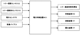
まず、本実施形態の複写機の画像濃度制御に係る構成の第1の実施例である、実施例1から説明する。本実施例の複写機では、画像濃度制御手段の1つとして、電位制御装置401を持っている。電位制御装置401は、図6に示すような情報を用いることで、適切に行うことが可能である。具体的には、トナー像検知センサ310で検知した検出値と、トナー濃度センサ312で検知した現像容器内のトナー濃度と、電位センサ70によって検知した感光体の露光後の表面電位と、現像バイアスを入力する。そして、電位制御装置は帯電装置60、現像装置61、露光装置21の帯電バイアス、現像バイアス、露光光量とトナー濃度制御目標値を出力する。この最適な作像条件にしたがって、各バイアス、トナー補給を制御することで、安定的な画像濃度を提供している。ここで、本実施例のトナー像検知センサ310は図3に示す、正反射光のみを検出するタイプの光学センサである。
Example 1
First, Example 1 which is a first example of the configuration relating to image density control of the copying machine of the present embodiment will be described. The copying machine of this embodiment has a
電位制御装置401の制御フローについて、フローチャート図7を用いて説明する。本実施例では、電位制御装置401による画像濃度制御を、電源ON時や所定枚数(250枚)印刷後などの印刷動作と排他的に定期的に実行する。印刷と排他的に実行を行うのは、複数の濃度の異なる画像を作像する必要があるためである。まず、必要であれば、光学センサのLED光量の調整等を実行する(S1)。ここで、光学センサは現条件でのLED光量で、地肌部出力を検知して所定の範囲内(4.0±0.5[V])かどうか判定を行う。所定の範囲内であった場合には、LED光量を調整せずに次のフローへ進む。範囲外の場合には、地肌部出力が4.0±0.5[V]となるようにLED光量を調整して次のフローへと進む。
A control flow of the
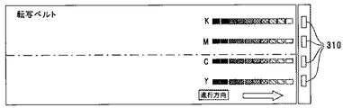
その後、図9に示すように、各色毎に濃度の異なる複数のパッチを間隔を開けて感光体40上に作像し(S2)、各パッチの潜像電位を電位センサ70で検出する(S3)。並行して、各パッチが現像装置61で現像されて中間転写ベルト10上に転写され、複数のトナー像となったパターン部のトナー像検知センサ310の出力(以下、パターン部出力という)を検知する(S5)。このときのトナー像検知センサ310から電位制御装置401への入力項目は、各パッチに対応する各トナー像のパターン部出力Vspと、パターン部の直前(又は直後)で検知した地肌部出力Vsgである。また、トナー濃度センサ312でトナー濃度を検知する(S8)。そして、検出した電位センサ70の出力から各パッチの潜像電位を検知して、現像ポテンシャル(現像バイアスVbと潜像電位Vlの差)を、それぞれ求める(S4)。
Thereafter, as shown in FIG. 9, a plurality of patches having different densities for each color are formed on the
トナー像検知センサ310による出力検知の方法については、次のように行なう。まず、トナー像検知センサ310の発光素子310aをONして発光させ、発光素子310aの出力が安定する時間(2秒)経過後に、正反射光を受光する受光素子310bの出力のセンシングを開始する。トナー像検知センサ310の受光素子310bのサンプリング周期は、電位制御装置401で作像する各パッチの(副走査)長さの半分以下の時間をサンプリングするのが望ましい。本実施例では、現像された各パッチのパターン長さ26[mm]に対して、10[mm]をサンプリング周期としている。また、各パッチの間の間隔は20[mm]としている。そして、地肌部のサンプリング周期を10[mm]とし、パターン部の直前又は直後の部分をサンプリングしている。また、各パッチの(主走査)幅は、12[mm]とし、中間転写ベルト10の幅に略均等になるように、各色に対応したトナー像検知センサ310を配置している。
The output detection method by the toner
そして、トナー像検知センサ310の各パッチに対応する各トナー像の出力と地肌部の出力(以下、地肌部出力という)とを用いてトナー付着量に変換する(S6)。本実施例では、地肌部出力Vsgとパターン部出力Vspの値のトナー付着量への変換は、予め実験的に求めた地肌部出力Vsgとパターン部出力Vspの比(Vsp/Vsg)の値とトナー付着量との関係式に基づき変換を行なっている。
Then, the output of each toner image corresponding to each patch of the toner
このように求めた、現像ポテンシャルとトナー付着量との関係から、現像能力(横軸に現像ポテンシャル、縦軸にトナー付着量としたときの傾き)を求める。現像能力から所定の画像濃度となるような現像ポテンシャルを算出する。これにより、現像バイアスや帯電バイアス、露光光量といった作像条件を決定する。また、このときのトナー濃度センサ312で検知したトナー濃度に基づき、トナー濃度制御目標値を決定する(または補正する)。以上のような一連の電位制御フローでは図示していないが、検出値全てに対して適正な出力範囲が予め決定されており、適正な出力範囲外であれば異常停止する異常停止手段を備える。出力異常の場合には、通知手段によって異常を通知できるようになっている。このようにして、本実施例の複写機では、電位制御装置401を用いて画像濃度制御を実行する事で、高品質が画像を提供している。
From the relationship between the development potential and the toner adhesion amount obtained in this way, the development ability (the slope when the development potential is plotted on the horizontal axis and the toner adhesion amount on the vertical axis) is determined. A development potential that gives a predetermined image density is calculated from the development ability. Thus, image forming conditions such as a developing bias, a charging bias, and an exposure light amount are determined. Further, the toner density control target value is determined (or corrected) based on the toner density detected by the
図8に実験的に求めた、C(シアン)に対応するパターン部におけるトナー付着量とトナー像検知センサ310出力の関係を示す。これは、中間転写ベルト10の光沢度が高いベルトと低いベルトを用意して、濃度の異なる複数のトナーパターンを作成し、トナー付着量とトナー像検知センサ310(受光素子310b)出力を測定したものである。光沢度が平均的なベルトでLED光量を調整して、その光量で他のベルトの測定を実施している。図8に示す通り、0〜0.2[mg/cm2]の領域でそれぞれの条件のプロットが異なっており、トナー付着量が高くなるにつれプロットが重なっていないことが分かる。つまり、低付着量領域では、光沢度によってパターン部出力が変動してしまい、トナー付着量検知誤差の要因となってしまう。本測定では実験的に光沢度の異なるベルトを使用しているが、同一のベルトでも、周内でこの程度の光沢度変動は往々にしてある。低付着量領域では、トナーが中間転写ベルト10上に付着しているとはいえ、ベルト地肌部も露出しているので、地肌部出力変動のパターン部出力への影響が大きくなっている。トナー付着量が大きくなると、ベルト地肌部の露出はなくなってくるので、地肌部出力変動の影響がなくなっている。
FIG. 8 shows the relationship between the toner adhesion amount in the pattern portion corresponding to C (cyan) and the output of the toner
本実施例では、中間転写ベルト10の地肌部出力検知をパターン部出力検知の直前(又は直後)に行うという簡便な方法で、パターン部出力Vspの検知と、その直前(又は直後)の地肌部出力Vsgとを検知している。そして、このパターン部出力Vspと地肌部出力Vsgとの検知箇所を、中間転写ベルトクリーニング装置17の位置を通過していない状態で行なっている。このため、従来のように地肌部出力Vsgの変動に起因したパターン部出力Vspの検知誤差の補正を、パターン部出力Vspの検知の前に中間転写ベルト10を1周回転させて地肌部出力Vsgを検知し、地肌部出力Vsgとパターン部出力Vspとの検知箇所を合わせて行えない。
In this embodiment, the detection of the pattern portion output Vsp and the background portion immediately before (or immediately after) the pattern portion output Vsp are performed by a simple method of detecting the background portion output of the
しかしながら、パターン部出力Vspを検知する中間転写ベルト10上の箇所において、中間転写ベルト10の光沢度等の表面の光学特性に不規則な変化が、中間転写ベルトクリーニング装置17を通過する前後で生じることを防げる。つまり、地肌部出力Vsgの検知と、パターン部出力Vspの検知とで、地肌部の表面の光学特性が異なった状態で、パターン部出力Vspを検知することを防げる。よって、地肌部出力Vsgの検知とパターン部出力Vspの検知とで、地肌部の表面の光学特性が異なることに起因したトナー付着量の検知誤差を、従来に比べ低減することができる。
However, an irregular change in the surface optical characteristics such as the glossiness of the
また、パターン部の検知を行なう前に像担持体を1周させて地肌部のセンサ出力をサンプリングする時間を省略できるとともに、サンプリングした地肌部の検知箇所と、パターン部の検知箇所との位相合わせの必要もない。したがって、従来の構成に比べ簡便な方法でトナー像検知センサ310の地肌部出力Vsgが変動することによって生じるトナー付着量検知誤差を低減できる。
In addition, it is possible to omit the time to sample the sensor output of the background portion by making one rotation of the image carrier before detecting the pattern portion, and to adjust the phase of the detected portion of the sampled background portion and the detected portion of the pattern portion. No need for Therefore, it is possible to reduce the toner adhesion amount detection error caused by the change in the background portion output Vsg of the toner
ここで、トナー付着量の変換時に、パターン部出力を検知する、その位置での地肌部出力Vsgを用いれば、トナー付着量検知誤差がなくなることがわかっている。しかしながら、パターン部出力と同じ位置で、地肌部出力を同時に検知することは不可能である。そして、従来のように、パターン部出力の検知に先立ち像担持体を1周させて地肌部出力を検知する構成では、地肌部出力を検知した検知位置が、中間転写ベルトクリーニング装置17を通過した後に、パターン部出力を検知することになる。そのため、中間転写ベルトクリーニング装置の位置を通過する前後で、上述した図8における光沢度が異なる中間転写ベルトを用いたように、部分的に中間転写ベルトの表面状態に違いが生じることが考えられる。
Here, it is known that the toner adhesion amount detection error is eliminated if the background portion output Vsg at the position where the pattern portion output is detected at the time of conversion of the toner adhesion amount is used. However, it is impossible to simultaneously detect the background portion output at the same position as the pattern portion output. Then, as in the prior art, in the configuration in which the image carrier is rotated once before the pattern portion output is detected and the background portion output is detected, the detection position where the background portion output is detected has passed through the intermediate transfer
そして、パターン部出力を検知する際の地肌部の表面状態が、地肌部出力を検知した際の地肌部の表面状態とは異なってしまうと、トナー付着量に変換を行う際に、トナー付着量の検知誤差が生じることとなる。また、図8では、光沢度が低い中間転写ベルトと光沢度が高い中間転写ベルトとでは低付着量領域では、パターン部出力に最大で約0.5Vの差が生じている。 Then, if the surface state of the background portion when detecting the pattern portion output is different from the surface state of the background portion when detecting the background portion output, the toner attachment amount is converted into the toner attachment amount. Detection error will occur. Further, in FIG. 8, there is a maximum difference of about 0.5 V in the pattern portion output in the low adhesion amount region between the intermediate transfer belt having a low glossiness and the intermediate transfer belt having a high glossiness.
そこで、本実施例では、中間転写ベルト10の地肌部出力Vsg検知をパターン部出力Vsp検知の直前(又は直後)に行うという簡便な方法で、パターン部出力Vspの検知の直前(又は直後)の地肌部出力Vsgを検知している。したがって、中間転写ベルト10上の地肌部出力Vsgとパターン部出力Vspとの検知箇所がずれてしまう。そのため、中間転写ベルト10表面とトナー像検知センサ310との距離変動に起因したトナー付着量の検知誤差の補正を、従来の構成のように地肌部出力Vsgとパターン部出力Vspとの検知位置を合わせて行うことはできない。
Therefore, in the present embodiment, the background portion output Vsg detection of the
しかしながら、地肌部出力の検知をパターン部出力Vspの検知の直前(又は直後)に行なうので、中間転写ベルト10上の地肌部出力Vsgとパターン部出力Vspとの検知箇所がクリーニング装置を通過する前に、パターン部出力と地肌部出力とを検知することができる。このことで、従来のように、パターン部出力Vspを検知する検知箇所で地肌部出力Vsgを検知し、この検知箇所が1周回転してクリーニング装置を通過することで、地肌部の表面の光学特性が大きく変化した状態で、パターン部出力Vspを検知することを防げる。つまり、地肌部出力Vsgを検知した際と、パターン部出力Vspを検知する際とで、地肌部の表面の光学特性が大きく異なった状態で、パターン部出力Vspを検知することを防げる。よって、地肌部出力Vsgの検知時とパターン部出力Vspの検知時とで、地肌部の表面の光学特性が異なることに起因したトナー付着量の検知誤差を、従来に比べ低減することができる。また、パターン部の検知を行なう前に中間転写ベルト10を1周させて地肌部出力Vsgをサンプリングする時間を省略できる。
However, since the detection of the background portion output is performed immediately before (or immediately after) the detection of the pattern portion output Vsp, before the detection portion of the background portion output Vsg and the pattern portion output Vsp on the
さらに、トナー付着量の影響を受けない地肌部出力Vsgとトナー付着量を反映したパターン部出力Vspとの出力比(Vsp/Vsg)に基づいてトナー付着量の変換を行っている。そして、従来のように、地肌部出力Vsgが変動した分だけパターン部出力Vspを補正する方法としていない。このことで、従来のトナー付着量の導出方法に比べ、地肌部出力Vsgの変動の影響を受けにくい。よって、トナー付着量に変換する際に、パターン部でのトナー付着量に応じて、地肌部出力Vsgの変動に対するパターン部出力Vspの変動幅に違いが生じることに起因したトナー付着量の検知誤差を最小化し、従来に比べ低減できる。また、本実施例のように、中間調も含む複数のパッチを有するパターン部を検知する場合には、より効果的に変換できる。 Further, the toner adhesion amount is converted based on the output ratio (Vsp / Vsg) between the background portion output Vsg not affected by the toner adhesion amount and the pattern portion output Vsp reflecting the toner adhesion amount. Then, unlike the conventional method, the pattern portion output Vsp is not corrected by an amount corresponding to the change in the background portion output Vsg. This makes it less susceptible to fluctuations in the background output Vsg compared to conventional methods for deriving the toner adhesion amount. Therefore, when converting to the toner adhesion amount, the detection error of the toner adhesion amount due to the difference in the fluctuation range of the pattern portion output Vsp with respect to the variation of the background portion output Vsg depending on the toner adhesion amount in the pattern portion. Can be minimized and reduced compared to the prior art. Further, as in this embodiment, when a pattern portion having a plurality of patches including halftones is detected, conversion can be performed more effectively.
ここで、トナー像検知センサ310としての光学センサは、本実施例に限らず、図5のように正反射光と拡散反射光の両者を検出するタイプの反射型センサであっても良い。正反射光と拡散反射光の両者を検出するタイプの反射型センサで、正反射光を受光する受光素子310bの出力を用いて、本実施例と同様にトナー付着量への変換を行うことで、トナー付着量検知誤差の小さい画像形成装置を提供できる。また、本実施例では地肌部出力Vsgとパターン部出力Vspの出力をそのまま演算に使っているが、オフセット電圧などキャンセルしても本発明の効果には影響がない。
Here, the optical sensor as the toner
また、本実施例では、2成分現像剤を用いる画像形成装置について説明したが、本発明は2成分現像剤を用いる画像形成装置に限定されるものではなく、例えば、1成分現像剤を用いる電写真方式の画像形成装置にも適用可能である。 In this embodiment, an image forming apparatus using a two-component developer has been described. However, the present invention is not limited to an image forming apparatus using a two-component developer. The present invention can also be applied to a photographic image forming apparatus.
また、本実施例では、中間転写ベルト上でトナー濃度の検知を行なう画像形成装置の例について説明した。しかし、本発明は中間転写ベルト上でのトナー濃度の検知を行う画像形成装置に限定されるものではなく、例えば、感光体上でトナー濃度の検知を行なうトナー画像形成装置にも適用可能である。 In this embodiment, the example of the image forming apparatus that detects the toner density on the intermediate transfer belt has been described. However, the present invention is not limited to the image forming apparatus that detects the toner density on the intermediate transfer belt, and can be applied to, for example, a toner image forming apparatus that detects the toner density on the photoreceptor. .
(実施例2)
次に、本実施形態の複写機の画像濃度制御に係る構成の第2の実施例である、実施例2から説明する。本実施例と上述した実施例1とは、次の点のみが異なる。本実施例の画像濃度制御では、地肌部出力をパターン部の直前(又は直後)に加え、各パッチの間のトナー像が形成されていない地肌部についても検知を行なう。そして、各パッチに対応する各トナー像のパターン部出力Vspと、それぞれのパッチに対応したトナー像の直前(又は直後)で検知した地肌部出力Vsgとの比(Vsp/Vsg)の値とトナー付着量との関係式に基づきトナー付着量に変換している点のみ異なる。したがって、他の共通する構成、作用・効果については、適宜省略して説明する。
(Example 2)
Next, Example 2 which is a second example of the configuration relating to image density control of the copying machine of the present embodiment will be described. This example differs from Example 1 described above only in the following points. In the image density control of the present embodiment, the background portion output is added immediately before (or immediately after) the pattern portion, and detection is also performed on the background portion where the toner image between the patches is not formed. The ratio (Vsp / Vsg) of the pattern portion output Vsp of each toner image corresponding to each patch and the background portion output Vsg detected immediately before (or immediately after) the toner image corresponding to each patch and the toner The only difference is that it is converted into the toner adhesion amount based on the relational expression with the adhesion amount. Therefore, other common configurations, operations and effects will be omitted as appropriate.
図10は、上述したように中間転写ベルト上の地肌部出力変動についての説明用のグラフである。より具体的には、この図10のグラフは、中間転写ベルト10を回転させてトナー像検知センサ310で地肌部出力Vsgを検知した結果である。地肌部出力Vsgの変動要因としては、トナー像検知センサ310と中間転写ベルト10の空間的な位置関係のズレ、中間転写ベルト10の表面の光沢度の周内偏差等が挙げられる。図10に示した検知結果は、光沢度の周内偏差の大きな中間転写ベルトを配置したものであり、出力が大きく変動する事が分かる。このようなに地肌部出力が大きく変動してしまうと、トナー付着量検知誤差の原因となってしまう。そして、実施例1の地肌部出力Vsgを検知する位置だけでは、パターン部の各パッチの数が多くなったり、上述したように、光沢度の周内偏差が大きな中間転写ベルトであった場合には、トナー付着量検知誤差が許容できる範囲を超えてしまうことも考えられる。
FIG. 10 is a graph for explaining the background portion output fluctuation on the intermediate transfer belt as described above. More specifically, the graph of FIG. 10 is a result of detecting the background output Vsg by the toner
そこで、本実施例では、地肌部出力をパターン部の直前(又は直後)に加え、各パッチの間のトナー像が形成されていない地肌部についても検知を行なうこととした。そして、それぞれのパッチに対応したトナー像の直前(又は直後)で検知した地肌部出力Vsgとの比(Vsp/Vsg)の値とトナー付着量との関係式に基づきトナー付着量に変換することとした。地肌部出力Vsgをきめ細かく検知することで、トナー像検知センサ310と中間転写ベルト10の空間的な位置関係のズレ、中間転写ベルト10の表面の光沢度の周内偏差等の影響を実施例1よりも小さく抑えることができ、地肌部出力Vsgが変動することによって生じるトナー付着量の検知誤差を、より低減できる。
Therefore, in this embodiment, the background portion output is added immediately before (or immediately after) the pattern portion, and detection is also performed for the background portion where the toner image between the patches is not formed. Then, based on the relational expression between the ratio (Vsp / Vsg) of the background portion output Vsg detected immediately before (or immediately after) the toner image corresponding to each patch and the toner adhesion amount, it is converted into the toner adhesion amount. It was. By detecting finely the background output Vsg, the effects of the spatial positional deviation between the toner
以上、本実施形態の画像形成装置である複写機では、中間転写ベルト10の地肌部出力Vsgの検知をパターン部出力Vspの検知の直前(又は直後)に行うという従来に比べ簡便な方法で、パターン部出力Vspの検知の直前(又は直後)の地肌部出力Vsgを検知している。したがって、中間転写ベルト10上の地肌部出力Vsgとパターン部出力Vspとの検知箇所がずれてしまう。このため、従来のように地肌部出力Vsgの変動に起因したパターン部出力Vspの検知誤差の補正を、パターン部出力Vspの検知の前に中間転写ベルト10を1周回転させて地肌部出力Vsgを検知し、地肌部出力Vsgとパターン部出力Vspとの検知箇所を合わせて行えない。しかしながら、地肌部出力Vsgの検知をパターン部出力Vspの検知の直前(又は直後)に行なうので、地肌部出力Vsgとパターン部出力Vspとの中間転写ベルト10上の検知箇所が中間転写ベルトクリーニング装置17を通過する前に、パターン部出力Vspと地肌部出力Vsgとを検知することができる。このことで、従来のように、パターン部出力Vspを検知する中間転写ベルト10上の箇所において、中間転写ベルト10の光沢度等の表面の光学特性に不規則な変化が、中間転写ベルトクリーニング装置17を通過する前後で生じることを防げる。つまり、地肌部出力Vsgの検知と、パターン部出力Vspの検知とで、地肌部の表面の光学特性が異なった状態で、パターン部出力Vspを検知することを防げる。よって、地肌部出力Vsgの検知とパターン部出力Vspの検知とで、地肌部の表面の光学特性が異なることに起因したトナー付着量の検知誤差を、従来に比べ低減することができる。また、パターン部出力Vspの検知を行なう前に中間転写ベルト10を1周させて地肌部出力Vsgをサンプリングする時間を省略できる。
さらに、トナー付着量の影響を受けない地肌部出力Vsgとトナー付着量を反映したパターン部出力Vspとの比(Vsp/Vsg)に基づいてトナー付着量に変換しており、従来のように、地肌部出力Vsgが変動した分だけパターン部出力Vspを補正して、補正したパターン部出力Vspをトナー付着量に変換する方法としていない。このことで、従来のトナー付着量の導出方法に比べ、地肌部出力Vsgの変動の影響を受けにくい。よって、トナー付着量に変換する際に、パターン部でのトナー付着量に応じて、地肌部出力Vsgの変動に対するパターン部出力Vspの変動幅に違いが生じることに起因したトナー付着量の検知誤差を従来に比べ低減できる。
また、本実施形態の画像形成装置である複写機では、地肌部出力をパターン部の直前(又は直後)に加え、各パッチの間のトナー像が形成されていない地肌部についても検知を行なっている。このことで、トナー像検知センサ310と中間転写ベルト10の空間的な位置関係のズレ、中間転写ベルト10の表面の光沢度の周内偏差等の影響を実施例1よりも小さく抑えることができる。そして、それぞれのパッチに対応したトナー像の直前(又は直後)で検知した地肌部出力Vsgとの比(Vsp/Vsg)の値とトナー付着量との関係式に基づきトナー付着量に変換する。このことで、地肌部出力Vsgが変動することによって生じるトナー付着量の検知誤差を、上述した実施形態より低減できる。
また、本実施形態の画像形成装置である複写機では、トナー像検知センサ310で検知する対象が、感光体40等のアルミ素管などを用いた円筒状の像担持体と比較して、中間転写ベルト10は、表面の光沢度変動、厚みのばらつき、回転による振動が大きく、トナー像検知センサ310の地肌部出力Vsgの変動が大きい中間転写ベルト10である。しかし、本発明を適用することで、このような中間転写ベルト10であっても、地肌部出力Vsg変動よって生じるトナー像検知センサ310の検知誤差を低減し、高品質な画像を提供することができる。
また、本実施形態の画像形成装置である複写機では、トナー像検知センサ310は、少なくとも正反射光出力を用いてトナー付着量に変換するので、従来、特に特に地肌部出力Vsgの出力変動の影響が大きかった正反射出力から付着量へ変換する際の、トナー付着量検知誤差を低減し、高画質な画像を提供するのに有効である。
また、本実施形態の画像形成装置である複写機では、トナー像検知センサ310が検知するトナーパターンは、少なくとも1つは中間調パターンを含んでいるので、従来、特に地肌部出力Vsgの出力変動の影響が大きかった中間調パターンをトナー付着量に変換する際のトナー付着量検知誤差を低減し、高画質な画像を提供するのに有効である。
As described above, in the copying machine as the image forming apparatus according to the present embodiment, the background portion output Vsg of the
Further, the toner adhesion amount is converted based on the ratio (Vsp / Vsg) of the background portion output Vsg not affected by the toner adhesion amount and the pattern portion output Vsp reflecting the toner adhesion amount. There is no method for correcting the pattern portion output Vsp by the amount of change in the background portion output Vsg and converting the corrected pattern portion output Vsp into the toner adhesion amount. This makes it less susceptible to fluctuations in the background output Vsg compared to conventional methods for deriving the toner adhesion amount. Therefore, when converting to the toner adhesion amount, the detection error of the toner adhesion amount due to the difference in the fluctuation range of the pattern portion output Vsp with respect to the variation of the background portion output Vsg depending on the toner adhesion amount in the pattern portion. Can be reduced as compared with the prior art.
Further, in the copying machine that is the image forming apparatus of the present embodiment, the background output is applied immediately before (or immediately after) the pattern portion, and the background portion where the toner image between the patches is not formed is also detected. Yes. As a result, the influence of the spatial positional deviation between the toner
Further, in the copying machine that is the image forming apparatus of the present embodiment, the object detected by the toner
Further, in the copying machine that is the image forming apparatus of the present embodiment, the toner
In the copying machine that is the image forming apparatus according to the present embodiment, at least one of the toner patterns detected by the toner
10 中間転写ベルト
18 画像形成部
20 タンデム型画像形成部
21 露光装置
22 2次転写装置
25 定着装置
40 感光体
60 帯電装置
61 現像装置
62 1次転写バイアスローラ
70 電位センサ
100 プリンタ部
200 給紙テーブル
300 スキャナ
310 トナー像検知センサ
310a 発光素子
310c 拡散反射光を受光する受光素子
310b 正反射光を受光する受光素子
311 光学センサ対向ローラ
312 トナー濃度センサ
400 原稿自動搬送装置
401 電位制御装置
DESCRIPTION OF
Claims (6)
該像担持体上に発光素子から光を照射するとともに、反射した光を受光素子で受光し、その受光量に応じた出力をするトナー像検知手段と、
上記担持体上に画像濃度検出用のトナー像のパターンを形成するパターン形成手段とを備え、
上記像担持体上に形成されたパターン部のトナー像を、上記トナー像検知手段で検知した検知情報であるパターン部出力と、
トナー像が形成されていない上記像担持体上の地肌部を、上記トナー像検知手段で検知した検知情報である地肌部出力とに基づいて画像濃度を適正に制御する画像形成装置において、
地肌部出力検知はパターン部出力検知の直前に行い、検知した地肌部出力とパターン部出力のと比に基づいてトナー付着量に変換し、この変換したトナー付着量により画像濃度を適正に制御することを特徴とする画像形成装置。 An image carrier;
A toner image detecting means for irradiating light on the image carrier from a light emitting element and receiving the reflected light by a light receiving element and outputting according to the amount of received light;
Pattern forming means for forming a toner image pattern for image density detection on the carrier,
A pattern portion output which is detection information detected by the toner image detection means for the toner image of the pattern portion formed on the image carrier;
In the image forming apparatus that appropriately controls the image density based on the background portion output that is detection information detected by the toner image detection unit, the background portion on the image carrier on which the toner image is not formed,
The background portion output detection is performed immediately before the pattern portion output detection, and is converted into the toner adhesion amount based on the ratio of the detected background portion output to the pattern portion output, and the image density is appropriately controlled by the converted toner adhesion amount. An image forming apparatus.
該像担持体上に発光素子から光を照射するとともに、反射した光を受光素子で受光し、その受光量に応じた出力をするトナー像検知手段と、
上記担持体上に画像濃度検出用のトナー像のパターンを形成するパターン形成手段とを備え、
上記像担持体上に形成されたパターン部のトナー像を、上記トナー像検知手段で検知した検知情報であるパターン部出力と、
トナー像が形成されていない上記像担持体上の地肌部を、上記トナー像検知手段で検知した検知情報である地肌部出力とに基づいて画像濃度を適正に制御する画像形成装置において、
地肌部出力検知はパターン部出力検知の直後に行い、検知した地肌部出力とパターン部出力のと比に基づいてトナー付着量に変換し、この変換したトナー付着量により画像濃度を適正に制御することを特徴とする画像形成装置。 An image carrier;
A toner image detecting means for irradiating light on the image carrier from a light emitting element and receiving the reflected light by a light receiving element and outputting according to the amount of received light;
Pattern forming means for forming a toner image pattern for image density detection on the carrier,
A pattern portion output which is detection information detected by the toner image detection means for the toner image of the pattern portion formed on the image carrier;
In the image forming apparatus that appropriately controls the image density based on the background portion output that is detection information detected by the toner image detection unit, the background portion on the image carrier on which the toner image is not formed,
The background portion output detection is performed immediately after the pattern portion output detection, and is converted into a toner adhesion amount based on the ratio between the detected background portion output and the pattern portion output, and the image density is appropriately controlled by the converted toner adhesion amount. An image forming apparatus.
像担持体上に形成されたパターン部のトナー像は、複数のパッチのトナー像からなり、
上記複数のパッチは間隔を開けて像担持体上に形成されれおり、
地肌部出力検知はパターン部出力検知の直前又は直後に加え、各パッチの間のトナー像が形成されていない地肌部についても検知を行ない、
それぞれのパッチに対応したトナー像のパターン部出力と、そのトナー像の直前又は直後で検知した地肌部出力との比の値に基づきトナー付着量に変換することを特徴とする画像形成装置。 The image forming apparatus according to claim 1, wherein
The toner image of the pattern portion formed on the image carrier is composed of toner images of a plurality of patches,
The plurality of patches are formed on the image carrier at intervals,
In addition to immediately before or after the pattern portion output detection, the background portion output detection is also performed on the background portion where the toner image between the patches is not formed.
An image forming apparatus that converts a toner adhesion amount based on a ratio value between a pattern portion output of a toner image corresponding to each patch and a background portion output detected immediately before or after the toner image.
像担持体は中間転写ベルトであることを特徴とするが画像形成装置。 The image forming apparatus according to any one of claims 1 to 3,
An image forming apparatus, wherein the image carrier is an intermediate transfer belt.
トナー像検知手段は、少なくとも正反射光出力を用いてトナー付着量を算出することを特徴とする画像形成装置。 The image forming apparatus according to any one of claims 1 to 4,
An image forming apparatus, wherein the toner image detecting means calculates a toner adhesion amount using at least a regular reflection light output.
トナー像検知手段が検知するトナー像パターンの少なくとも1つは中間調パターンを含むことを特徴とする画像形成装置。 The image forming apparatus according to any one of claims 1 to 5,
An image forming apparatus, wherein at least one of the toner image patterns detected by the toner image detecting means includes a halftone pattern.
Priority Applications (1)
| Application Number | Priority Date | Filing Date | Title |
|---|---|---|---|
| JP2011044990A JP2012181414A (en) | 2011-03-02 | 2011-03-02 | Image forming apparatus |
Applications Claiming Priority (1)
| Application Number | Priority Date | Filing Date | Title |
|---|---|---|---|
| JP2011044990A JP2012181414A (en) | 2011-03-02 | 2011-03-02 | Image forming apparatus |
Publications (1)
| Publication Number | Publication Date |
|---|---|
| JP2012181414A true JP2012181414A (en) | 2012-09-20 |
Family
ID=47012651
Family Applications (1)
| Application Number | Title | Priority Date | Filing Date |
|---|---|---|---|
| JP2011044990A Pending JP2012181414A (en) | 2011-03-02 | 2011-03-02 | Image forming apparatus |
Country Status (1)
| Country | Link |
|---|---|
| JP (1) | JP2012181414A (en) |
Cited By (5)
| Publication number | Priority date | Publication date | Assignee | Title |
|---|---|---|---|---|
| US9494889B2 (en) | 2012-12-19 | 2016-11-15 | Canon Kabushiki Kaisha | Image forming apparatus and detection apparatus |
| US9565319B2 (en) | 2014-10-17 | 2017-02-07 | Ricoh Company, Ltd. | Image forming apparatus having an optical sensor for converting a toner adhesion amount and image forming method |
| US9576229B2 (en) | 2012-12-19 | 2017-02-21 | Canon Kabushiki Kaisha | Image forming apparatus and detection apparatus |
| US9885990B2 (en) | 2012-12-19 | 2018-02-06 | Canon Kabushiki Kaisha | Image forming apparatus and detection apparatus for detecting position or density information of detection image |
| US10481514B2 (en) | 2017-08-10 | 2019-11-19 | Ricoh Company, Ltd. | Image forming apparatus and image forming method |
Citations (10)
| Publication number | Priority date | Publication date | Assignee | Title |
|---|---|---|---|---|
| JPH0430182A (en) * | 1990-05-28 | 1992-02-03 | Ricoh Co Ltd | Electrophotographic system image forming device |
| JPH04250479A (en) * | 1991-01-28 | 1992-09-07 | Ricoh Co Ltd | Image density control method |
| JP2002214854A (en) * | 2001-01-19 | 2002-07-31 | Seiko Epson Corp | Image forming apparatus |
| JP2005134932A (en) * | 1997-08-18 | 2005-05-26 | Ricoh Co Ltd | Image forming apparatus |
| JP2005352366A (en) * | 2004-06-14 | 2005-12-22 | Ricoh Co Ltd | Developer concentration control method and image forming device |
| JP2010008904A (en) * | 2008-06-30 | 2010-01-14 | Ricoh Co Ltd | Image forming apparatus |
| JP2010044218A (en) * | 2008-08-12 | 2010-02-25 | Ricoh Co Ltd | Image forming apparatus |
| JP2010072585A (en) * | 2008-09-22 | 2010-04-02 | Kyocera Mita Corp | Image forming apparatus |
| JP2010101943A (en) * | 2008-10-21 | 2010-05-06 | Ricoh Co Ltd | Image forming apparatus |
| JP2011075838A (en) * | 2009-09-30 | 2011-04-14 | Kyocera Mita Corp | Image forming apparatus and image density correcting method |
-
2011
- 2011-03-02 JP JP2011044990A patent/JP2012181414A/en active Pending
Patent Citations (10)
| Publication number | Priority date | Publication date | Assignee | Title |
|---|---|---|---|---|
| JPH0430182A (en) * | 1990-05-28 | 1992-02-03 | Ricoh Co Ltd | Electrophotographic system image forming device |
| JPH04250479A (en) * | 1991-01-28 | 1992-09-07 | Ricoh Co Ltd | Image density control method |
| JP2005134932A (en) * | 1997-08-18 | 2005-05-26 | Ricoh Co Ltd | Image forming apparatus |
| JP2002214854A (en) * | 2001-01-19 | 2002-07-31 | Seiko Epson Corp | Image forming apparatus |
| JP2005352366A (en) * | 2004-06-14 | 2005-12-22 | Ricoh Co Ltd | Developer concentration control method and image forming device |
| JP2010008904A (en) * | 2008-06-30 | 2010-01-14 | Ricoh Co Ltd | Image forming apparatus |
| JP2010044218A (en) * | 2008-08-12 | 2010-02-25 | Ricoh Co Ltd | Image forming apparatus |
| JP2010072585A (en) * | 2008-09-22 | 2010-04-02 | Kyocera Mita Corp | Image forming apparatus |
| JP2010101943A (en) * | 2008-10-21 | 2010-05-06 | Ricoh Co Ltd | Image forming apparatus |
| JP2011075838A (en) * | 2009-09-30 | 2011-04-14 | Kyocera Mita Corp | Image forming apparatus and image density correcting method |
Cited By (5)
| Publication number | Priority date | Publication date | Assignee | Title |
|---|---|---|---|---|
| US9494889B2 (en) | 2012-12-19 | 2016-11-15 | Canon Kabushiki Kaisha | Image forming apparatus and detection apparatus |
| US9576229B2 (en) | 2012-12-19 | 2017-02-21 | Canon Kabushiki Kaisha | Image forming apparatus and detection apparatus |
| US9885990B2 (en) | 2012-12-19 | 2018-02-06 | Canon Kabushiki Kaisha | Image forming apparatus and detection apparatus for detecting position or density information of detection image |
| US9565319B2 (en) | 2014-10-17 | 2017-02-07 | Ricoh Company, Ltd. | Image forming apparatus having an optical sensor for converting a toner adhesion amount and image forming method |
| US10481514B2 (en) | 2017-08-10 | 2019-11-19 | Ricoh Company, Ltd. | Image forming apparatus and image forming method |
Similar Documents
| Publication | Publication Date | Title |
|---|---|---|
| JP5382491B2 (en) | Image forming apparatus | |
| US8811834B2 (en) | Image forming apparatus | |
| JP4759433B2 (en) | Image forming apparatus | |
| JP2007148134A (en) | Picture quality control device, image forming apparatus, and picture quality control method | |
| JP2014119713A (en) | Image forming apparatus | |
| US9436135B2 (en) | Toner pattern density correction in an image forming apparatus | |
| JP2012181414A (en) | Image forming apparatus | |
| US9565319B2 (en) | Image forming apparatus having an optical sensor for converting a toner adhesion amount and image forming method | |
| US8938174B2 (en) | Image forming apparatus and image forming method | |
| US7865095B2 (en) | Image forming apparatus including distance detection unit | |
| JP5272105B2 (en) | Image forming apparatus | |
| JP5370856B2 (en) | Image forming apparatus | |
| JP2015166846A (en) | Control apparatus which determines exposure energy to be used for image formation, and image forming apparatus using the same | |
| JP5445955B2 (en) | Image forming apparatus | |
| JP2008164656A (en) | Image forming apparatus | |
| JP4750307B2 (en) | Development device | |
| JP2017003715A (en) | Image forming apparatus | |
| JP2005309050A (en) | Image forming apparatus | |
| JP2016177139A (en) | Image formation device | |
| JP2002214855A (en) | Surface condition detecting method, toner quantitative measurement method, and image forming apparatus | |
| US10466614B2 (en) | Developing device, image forming apparatus, and developing condition correcting method | |
| JP5574234B2 (en) | Image forming apparatus | |
| JP2005275119A (en) | Image forming apparatus | |
| JP2009251304A (en) | Image forming apparatus | |
| JP4638994B2 (en) | Tandem image forming apparatus |
Legal Events
| Date | Code | Title | Description |
|---|---|---|---|
| A621 | Written request for application examination |
Free format text: JAPANESE INTERMEDIATE CODE: A621 Effective date: 20140214 |
|
| A977 | Report on retrieval |
Free format text: JAPANESE INTERMEDIATE CODE: A971007 Effective date: 20141126 |
|
| A131 | Notification of reasons for refusal |
Free format text: JAPANESE INTERMEDIATE CODE: A131 Effective date: 20141128 |
|
| A02 | Decision of refusal |
Free format text: JAPANESE INTERMEDIATE CODE: A02 Effective date: 20150403 |