JP2012180733A - Water area purification fence - Google Patents
Water area purification fence Download PDFInfo
- Publication number
- JP2012180733A JP2012180733A JP2011100068A JP2011100068A JP2012180733A JP 2012180733 A JP2012180733 A JP 2012180733A JP 2011100068 A JP2011100068 A JP 2011100068A JP 2011100068 A JP2011100068 A JP 2011100068A JP 2012180733 A JP2012180733 A JP 2012180733A
- Authority
- JP
- Japan
- Prior art keywords
- water
- water purification
- flow rate
- purification
- fence
- Prior art date
- Legal status (The legal status is an assumption and is not a legal conclusion. Google has not performed a legal analysis and makes no representation as to the accuracy of the status listed.)
- Granted
Links
Images


Landscapes
- Cleaning Or Clearing Of The Surface Of Open Water (AREA)
Abstract
Description
本発明は、水域浄化フェンスに関する。本発明は、より詳しくは、水浄化領域の面積(吸着剤や微生物付着担体の量)及び水流量調節領域の面積(透水性やろ過性)を浄化の状況に応じて容易に変更することができる水域浄化フェンスに関する。 The present invention relates to a water purification fence. More specifically, the present invention can easily change the area of the water purification region (the amount of the adsorbent and the microorganism-adhering carrier) and the area of the water flow rate adjustment region (water permeability and filterability) according to the state of purification. It relates to a water purification fence that can be used.
従来、汚濁防止、一定水域の水質浄化、流出した油類の拡散防止や回収等のために、平面状のフェンス(以下、総じて「水域浄化フェンス」ともいう。)が使用されている。 Conventionally, a flat fence (hereinafter also referred to as a “water purification fence”) has been used for preventing pollution, purifying water in a certain water area, preventing diffusion and recovery of spilled oil, and the like.
以下の特許文献1には、フロート部、スカート部及びアンカー部を備えた汚濁物質の水中拡散防止フェンスにおいて、スカート部表面に必要に応じ除去できる補助膜が取付けてあることを特徴とする汚濁物質の水中拡散防止フェンスが開示されている。
In the following
以下の特許文献2には、浮き体を浮上させて汚濁防止膜を垂下させるか重錘を水底に着床させて汚濁防止膜を浮き体により水中に立ち上がらせることにより水域に設けられる汚濁防止フェンスにおいて、汚濁防止膜は索条体からなる骨格部と膜体からなり、これらの骨格部、膜体及び上記浮き体、重錘を部材として適宜選択しかつ上記いずれかの形態又はこれらを組み合わせた形態に組立可能に設け、膜体を骨格部の任意の位置に現場の具体的状況に合わせて取りつけ可能にするとともに上記骨格部、浮き体、重錘の連結部の任意の個所の連結部を円形可撓性緩衝体を介して行なうことを特徴とする現場組立用汚濁防止フェンスが開示されている。
In
以下の特許文献3には、海洋において作業をする際に発生する汚物が所定範囲から外方へ拡散することを防止する防止膜の構造であつて、防止膜は芯体とこの芯体の表裏面の少なくとも片面に着脱自在に重合被覆された被膜布とを有してなると共にこの防止膜の下縁は海底に係着され上縁には浮材が取付けられてなることを特徴とする海洋汚濁防止膜構造が開示されている。
以下の特許文献4には、水面に浮上するフロートに汚濁防止膜が吊設され、且つ、該汚濁防止膜の下端部には重錘が取付けられて成る汚濁防止装置において、上記汚濁防止膜の構成部材であるカーテンは所定サイズの合成樹脂材から成り、且つ、前記フロートには合成樹脂製のテンションベルトが連結されており、該テンションベルトには汚濁防止膜として配設せらるべき各カーテンの周縁部の対応位置に縦横の合成樹脂製の補強ベルトが配設されて格子状の枠部を形成し、最上段のカーテンの上端縁は前記テンションベルトに連結され、下方段の各カーテンの上端縁は夫々対応する枠部の各格子の上方部横方向補強ベルトに連結して下方部を開閉自在にし、且つ、該カーテンの下端縁に所定巾を有する高透水性膜体の一側縁を取付け、該高透水性膜体の他側縁を夫々対応する各格子の下方部横方向補強ベルトに連結して成る汚濁防止装置が開示されている。
In
以下の特許文献5には、両岸に張り渡したロープと、ロープから水中に垂下した流木止めネットと、ロープに係止しロープを水面上に支持するフロートよりなる網場において、前記ロープに植生浮島を連結して係留したことを特徴とする水質浄化用網場が開示されている。特許文献5に記載された発明は、自然景観を損ねることなく、水面の緑化と、表層部から深水部にわたる効率のよい水質浄化を行なうとともに、流木、塵芥をせき止めて回収することを課題としている。そのため網場に植生浮島を連結、或いは網場と植生浮島を一体に構成し、植生浮島の植生基盤材の中に水質浄化作用を有する微生物を固定化した粒子を封入した通水性の微生物容器を挿入し、下面に微生物を吸着する多孔質の合成樹脂よりなる複数個の接触ろ材を垂下している。 In the following Patent Document 5, a rope stretched across both banks, a driftwood retaining net hanging from the rope underwater, and a net that includes a float that is locked to the rope and supports the rope on the water surface, A network for water purification is disclosed which is characterized by connecting and mooring vegetation floating islands. The invention described in Patent Document 5 has an object of greening the water surface and efficiently purifying water from the surface layer portion to the deep water portion without damaging the natural landscape, and damaging and collecting driftwood and dust. . Therefore, connect the vegetation floating island to the Ambaba, or configure the Amboba and the vegetation floating island as one body, and install a water-permeable microbial container that encloses the particles that fix the water-cleaning microorganisms in the vegetation base material of the vegetation floating island. A plurality of contact filter media made of a porous synthetic resin that is inserted and adsorbs microorganisms are suspended on the lower surface.
以下の特許文献6には、正面形状が四角形で、かつ所定の厚さを有し、網材にて袋状に構成され、内部に中込材を充填してなる複数個の単位ネットを、それぞれの側辺で連結し、上側辺に、複数のフロートを連結し、さらに陸側に係留する索条を連結したことを特徴とする吊りネットが開示されている。特許文献6に記載された発明は、流木が岸辺に漂着するのを阻止でき、流水の流水を減殺すことができ、さらに、露出した岸辺を流木や波浪から保護することができるようにすることを課題としている。 In the following Patent Document 6, a plurality of unit nets each having a rectangular front shape and a predetermined thickness, configured in a bag shape with a net material, and filled with a filling material inside, A suspension net is disclosed in which a plurality of floats are connected to the upper side, and a rope moored to the land side is connected to the upper side. The invention described in Patent Document 6 can prevent driftwood from drifting to the shore, reduce running water, and protect the exposed shore from driftwood and waves. Is an issue.
さらに、以下の特許文献7には、袋状のネット内を、複数の区画に仕切部で区切り、該仕切部で区切られた各区画の各開閉部から、少なくとも1枚以上または1個以上の油吸着材を各区画毎に収納可能としたことを特徴とする油吸着機能性オイルネットが開示されている。特許文献7に記載された発明は、河川、海洋等の水面や路上等に流出した油類の拡散防止、吸着性能および回収除去作業に優れた吸着機能性オイルネットを提供することである。 Furthermore, in the following Patent Document 7, the bag-shaped net is divided into a plurality of compartments by partition portions, and at least one or more or one or more pieces from each opening / closing portion of each compartment partitioned by the partition portions. An oil adsorbing functional oil net characterized in that an oil adsorbing material can be stored in each section is disclosed. The invention described in Patent Document 7 is to provide an adsorption functional oil net excellent in diffusion prevention, adsorption performance and recovery / removal work of oils flowing out on the surface of water such as rivers and oceans, roads, and the like.
以上、特許文献1〜7には、様々な水域浄化フェンスが記載されているが、水浄化領域の面積(吸着剤や微生物付着担体の量)及び水流量調節領域の面積(透水性やろ過性)を、浄化の状況に応じて、簡易な操作で、適宜容易に変更することができる水域浄化フェンスは未だ提供されていない。
As mentioned above, although various water area purification fences are described in
前記した従来技術の状況に鑑み、本発明が解決しようとする課題は、水浄化領域の面積(吸着剤や微生物付着担体の量)及び水流量調節領域の面積(透水性やろ過性)を、浄化の状況に応じて、簡易な操作で、適宜容易に変更することができる水域浄化フェンスを提供することである。 In view of the situation of the prior art described above, the problems to be solved by the present invention are the area of the water purification region (the amount of the adsorbent and the microorganism adhesion carrier) and the area of the water flow rate adjustment region (the water permeability and filterability), An object of the present invention is to provide a water purification fence that can be changed easily and easily by a simple operation according to the state of purification.
本発明者は、前記課題を解決すべく、鋭意検討し実験を重ねた結果、以下の構成を有することにより、前記課題を解決しうることを見出し、本発明を完成するに至った。 As a result of intensive studies and repeated experiments to solve the above-mentioned problems, the present inventors have found that the above-described problems can be solved by having the following configuration, and have completed the present invention.
すなわち、本発明は、以下の通りのものである。
[1]フロート部材、水浄化部材、水流量調節部材、及びこれらを接続する接続手段を含む水域浄化フェンスであって、該水浄化部材と該水流量調節部材が共に、略四角形の平面パネル状の単位構成要素(ユニット)として形成され、所定数の水浄化部材ユニットと所定数の水流量調節部材ユニットが、略平面を呈するように接続され、該略平面に、一又は複数の前記フロート部材が接続されていることを特徴とする前記水域浄化フェンス。
That is, the present invention is as follows.
[1] A water purification fence including a float member, a water purification member, a water flow rate adjustment member, and a connecting means for connecting them, and the water purification member and the water flow rate adjustment member are both substantially rectangular flat panel shapes A predetermined number of water purification member units and a predetermined number of water flow rate adjustment member units are connected to form a substantially flat surface, and one or a plurality of the float members are formed on the substantially flat surface. Is connected to the water purification fence.
[2]前記フロート部材に、網からなる基材が、略平面を呈するように接続され、かかる基材に、所定数の水浄化部材ユニットと所定数の水流量調節部材ユニットが接続されている、前記[1]に記載の水域浄化フェンス。 [2] A base material made of a net is connected to the float member so as to exhibit a substantially flat surface, and a predetermined number of water purification member units and a predetermined number of water flow rate adjustment member units are connected to the base material. The water purification fence according to [1].
[3]所定数の水浄化部材ユニットと所定数の水流量調節部材ユニット同士が、直接接続されている、前記[1]に記載の水浄化フェンス。 [3] The water purification fence according to [1], wherein a predetermined number of water purification member units and a predetermined number of water flow rate adjustment member units are directly connected to each other.
[4]前記フロート部材の幅よりも広い幅の水浄化部材ユニット又は水流量調節部材ユニットが、該各フロートに縦方向に1列で接続され、短冊状を呈しており、各フロートが左右に隣接して敷設される際、左右に隣接するユニット同士が一部互いに重なるが、該ユニット同士は接続されていない、前記[2]又は[3]に記載の水浄化フェンス。 [4] A water purification member unit or a water flow rate adjustment member unit having a width wider than the width of the float member is connected to each float in a row in a vertical direction, has a strip shape, and each float is horizontally The water purification fence according to the above [2] or [3], wherein when laying adjacent to each other, the units adjacent to the left and right partially overlap each other, but the units are not connected to each other.
[5]前記水浄化部材は、複数の孔を配した略四角形の補強枠に固定した網からなる外袋の中に、より目の細かい網からなる単数又は複数の内袋の中に吸着剤を収容したものを、さらに収容した二重構造の袋体構造を有する、前記[1]〜[4]のいずれかに記載の水域浄化フェンス。 [5] The water purification member is adsorbent in an outer bag made of a mesh fixed to a substantially rectangular reinforcing frame having a plurality of holes, or in an inner bag made of a finer mesh. The water purification fence according to any one of the above [1] to [4], which has a double-structured bag structure in which a container containing a container is further stored.
[6]前記水流量調節部材は、複数の孔を配した略四角形の補強枠に固定した網、編物、織物、不織布又は非透水性シートである、前記[1]〜[5]のいずれかに記載の水域浄化フェンス。 [6] Any of the above [1] to [5], wherein the water flow rate adjusting member is a net, a knitted fabric, a woven fabric, a nonwoven fabric, or a water-impermeable sheet fixed to a substantially rectangular reinforcing frame provided with a plurality of holes. The water purification fence described in 1.
[7]前記接続手段による接続は、前記水浄化部材と前記水流量調節部材の補強枠に配した孔に、結束バンド、インシュロック(登録商標)、糸、紐、てぐす(天蚕糸)、針金、ロープ、安全ピン、クリップ又はフックの一部を通して行われる、前記[1]〜[6]のいずれかに記載の水域浄化フェンス。 [7] The connection by the connecting means is performed in a hole arranged in a reinforcing frame of the water purification member and the water flow rate adjusting member, a binding band, an Insulok (registered trademark), a thread, a string, a thread (tension thread), a wire The water purification fence according to any one of [1] to [6], which is performed through a part of a rope, a safety pin, a clip, or a hook.
[8]前記[1]〜[7]のいずれかに記載の水域浄化フェンスを使用することを特徴とする水域浄化方法。 [8] A water purification method using the water purification fence according to any one of [1] to [7].
[9]前記水域浄化フェンスを、前記略平面を、水面と略直交する方向に展張して設置する、前記[8]に記載の水域浄化方法。 [9] The water purification method according to [8], wherein the water purification fence is installed by extending the substantially flat surface in a direction substantially orthogonal to the water surface.
[10]前記水域浄化フェンスを、前記略平面を、水面と略平行する方向に展張して設置する、前記[8]に記載の水域浄化方法。 [10] The water purification method according to [8], wherein the water purification fence is installed by extending the substantially flat surface in a direction substantially parallel to the water surface.
本発明に係る水域浄化フェンスは、水浄化部材ユニット及び水流量調節部材ユニットを、水浄化の状況に応じて適宜選択し、それぞれ、所定数を略平面上に容易に配置又は変更することができるため、作業効率が向上し、ひいては最適な水域浄化に貢献する。 In the water purification fence according to the present invention, the water purification member unit and the water flow rate adjustment member unit can be appropriately selected according to the state of water purification, and each of the predetermined numbers can be easily arranged or changed on a substantially plane. As a result, work efficiency is improved, which in turn contributes to optimal water purification.
以下、本発明を詳細に説明する。
本発明は、フロート部材、水浄化部材、水流量調節部材、及びこれらを接続する接続手段を含む水域浄化フェンスであって、該水浄化部材と該水流量調節部材が共に、略四角形の平面パネル状の単位構成要素(ユニット)として形成され、所定数の水浄化部材ユニットと所定数の水流量調節部材ユニットが、該フロート部材に、略平面を呈するように、接続されていることを特徴とする前記水域浄化フェンスであり、その第一の態様においては、前記フロート部材に、網からなる基材が、略平面を呈するように接続され、かかる基材に、所定数の水浄化部材ユニットと所定数の水流量調節部材ユニットが接続されている。
Hereinafter, the present invention will be described in detail.
The present invention is a water area purification fence including a float member, a water purification member, a water flow rate adjustment member, and a connecting means for connecting them, and the water purification member and the water flow rate adjustment member are both substantially rectangular flat panels. A predetermined number of water purification member units and a predetermined number of water flow rate adjustment member units are connected to the float member so as to exhibit a substantially flat surface. In the first aspect of the present invention, in the first aspect, a base material made of a net is connected to the float member so as to exhibit a substantially flat surface, and a predetermined number of water purification member units are connected to the base material. A predetermined number of water flow rate adjusting member units are connected.
本明細書中、「水域」とは、河川、ダム、水路、湖沼、お堀、海等を含み、水が存在する領域である限り特に限定されない。
本明細書中、「浄化」とは、該水域内に存在する水のいずれかの性質が変化することをいい、特定の性質の変化を意味しない。
In the present specification, the “water area” includes rivers, dams, waterways, lakes, moats, seas, etc., and is not particularly limited as long as it is an area where water exists.
In the present specification, “purification” means that any property of water existing in the water area changes, and does not mean a change in a specific property.
本明細書中、「フェンス」とは、二次元の面を意味し、水域を閉じたものであってもなくてもよく、また、水底に届いていないものでもよく、また、可撓性を有するものであるかどうかを問わない。また、「フェンス」は、水域の水面から水底に向かって略垂直方向に展張したものであってもよく、水面と略平行に、すなわち、略水平方向に展張したものであってもよい。 In this specification, “fence” means a two-dimensional surface, which may or may not be closed to the water area, may not reach the bottom of the water, and is flexible. It does not matter whether or not it has. Further, the “fence” may be extended in a substantially vertical direction from the water surface of the water area toward the bottom of the water, or may be extended substantially in parallel with the water surface, that is, in a substantially horizontal direction.
本明細書中、「水浄化部材」とは、主に、水を浄化する機能を有する材料、例えば、塩類、窒素、リン、重金属、有機溶剤、放射性物質等の吸着剤、例えば、天然又は合成ゼオライト、有機物を分解する微生物の担体、例えば、活性炭、炭素繊維等を提供する部材である。 In the present specification, the “water purification member” mainly means a material having a function of purifying water, for example, an adsorbent such as salts, nitrogen, phosphorus, heavy metals, organic solvents, radioactive substances, for example, natural or synthetic It is a member that provides zeolite, a microorganism carrier that decomposes organic matter, such as activated carbon and carbon fiber.
本明細書中、「水流量調節部材」とは、主に、水が該部材を通過することを調節する機能を有するか、又は懸濁液物質(SS)、土砂の細粒成分、青粉、藻類、赤潮、プランクトン微生物等の浮遊物をろ過する機能を有する材料を提供する部材である。 In the present specification, the “water flow rate adjusting member” mainly has a function of adjusting the passage of water through the member, or is a suspension substance (SS), fine-grained component of earth and sand, blue powder It is a member that provides a material having a function of filtering suspended matters such as algae, red tides, and plankton microorganisms.
図3に、第一の態様を説明する。
フロート部材31は、略筒状の発泡スチロールや中空プラスチックなどからなるが水に浮く限り材質は特に限定されない。例えば、筒状の発泡スチロールにブルーシートを巻いたものでもよい。かかるフロート部材31は、長さ方向に複数個連結して使用することができる。該連結は、隣接する中空プラスチックのフロートの端同士をロープで連結することによるものであってもよいし、また、例えば、フロート部材31の中心部にロープを貫通させたり又は周縁部に複数のロープを長さ方向に沿わせたりすることにより行ってもよい。筒状フロート部材31の大きさは、例えば、直径670mm長さ1150mmであることができる。
FIG. 3 illustrates the first aspect.
The
第一の態様においては、フロート部材31に網からなる基材33が接続される。フロート部材は基材の一側面部だけでなく、基材の二以上の側面部に接続していてもよい。また、基材の略平面上に接続してもよい。網からなる基材33は、例えば、ポリエチレン製の防球ネットやジオグリッドであることができる。防球ネットは直径約4mm、40×40mmの格子状のポリエチレン製防球ネットであることができる。フロート部材31への基材33の接続は、特に限定されないが、フロート部材31が円筒状の発泡スチロールである場合、これを最大直径において2分割し、基材33をその間に挟みこみ、かかる後に、2分割されたフロート部材の外周を紐32できつく縛ることによるものであることができる。また、基材の端に金属チェーン等の錘を付けることも、また、アンカー等で水底に固定することもできる。
In the first aspect, a
図1に示すように、水流量調節部材10は、複数の鳩目を含む孔12を配した略四角形の補強枠11に固定した網、編物、織物、不織布又は非透水性シート13であることができる。補助枠は、所定の張力があれば可撓性であってもよく、補助枠と不織布等の固定は、ミシン糸等で縫い合わせる方法により行ってもよい。また、2つの補助枠の間に不織布等を挟み込んでもよい。また、補強枠の形状は、ユニットを形成する、すなわち、以下に説明する水浄化部材との互換性を有するために、略四角形であることが好ましいが、ユニットの形成を妨害しない限り、他の形状であっても構わない。
As shown in FIG. 1, the water flow
例えば、水の流出入を制限したい場合には、非透水性のシートや織り目の細かい織布を使用し、ある程度の流出入を許容する場合には、不織布を使用し、かなりの程度の水の流出入を許容する場合には、目の粗い編物又は網を使用することができる。これらの材質は特に問わないが、例えば、ポリエステル製の織布又は不織布である。ここで、留意すべきは、水流量調節部材は、ろ過や吸着剤や微生物の担体として機能することもできるということである。すなわち、「水流量調節部材」という名称であっても、水流量調節という機能だけではなく、水浄化の機能を兼ね備えることができる場合がある。補強枠11には、例えば、鳩目であることができる複数の孔12が設けられており、かかる孔に紐を通し、これをさらに前記した基材33の格子に通して、紐を結束することにより、水流量調節部材10を基材33に固定することができる。かかる接続は、例えば、紐に代えて、結束バンド、インシュロック(登録商標)、糸、てぐす(天蚕糸)、針金、ロープ、安全ピン、クリップ又はフックの一部を通して行われることもできる。水流量調節部材10は、例えば、一辺40cm〜2mの正方形であることができる。
For example, use water-impermeable sheets or finely woven fabrics to limit the inflow and outflow of water, and use non-woven fabrics to allow a certain amount of inflow and outflow. When allowing inflow and outflow, a coarse knitted fabric or net can be used. These materials are not particularly limited, and are, for example, polyester woven fabric or non-woven fabric. Here, it should be noted that the water flow rate adjusting member can also function as a filter, an adsorbent, or a microorganism carrier. That is, even the name “water flow rate adjusting member” may have not only the function of water flow rate adjustment but also the function of water purification. The reinforcing
図2に示すように、水浄化部材20は、複数の鳩目を含む孔22を配した略四角形の補強枠21に固定した網からなる外袋23の中に、より目の細かい網からなる単数又は複数の内袋24の中に吸着剤等を収容したものを、さらに収容した二重構造の袋体構造を有する。
As shown in FIG. 2, the
ここで、水浄化部材20の孔22と補強枠21の構造、基材33への固定方法、大きさは、前記した水流量調節部材10と同様である。但し、水浄化部材20においては、前記した不織布13等に代えて、微生物を吸着する機能を有する吸着剤等25、例えば、多孔質の合成樹脂よりなる複数の接触ろ材、牡蠣殻を再利用したもの、微生物を付着させた炭素繊維、猿頬貝の殻を再利用したもの、窒素、リン、重金属、有機溶剤、放射性物質等を吸着し、また微生物をも担持するゼオライト、活性炭、油吸着剤等を、こぼれないように充填した目の細かい網からなる単数又は複数の内袋24を収容したより目が粗く、かつ、より強度の高い線材からなる網からなる外袋23が、補強枠21に固定されている。ゼオライトは、窒素吸着後に回収して肥料にすることができるため、好ましい吸着剤である。ここで、留意すべきは、単数又は複数の内袋24の中に収容される材料は、浄化の状況に応じて、適宜交換されることができるということである。すなわち、「水浄化部材」という名称であっても、内袋内の材料の有無、種類によっては、水流量調節部材と同様の機能を発揮することができる場合がある。
Here, the structure of the
本発明に係る水域浄化フェンスは、水流量調節部材10と水浄化部材20が、それぞれ、互換性のあるユニットとして提供されることを特徴とする。これにより、水域浄化の状況に応じて、これらのユニットを適宜、簡単な操作で、交換し又は増減することにより、該フェンスを通過する水の流出入量、懸濁浮遊物のろ過性、吸着剤や微生物担体の量を調節して最適な浄化が可能となる。例えば、水深6mの水域浄化フェンス4枚で浄化すべき水域を取り囲む場合、水深1mまでは全て不透水シートの水流量調節部材10を配置し、水深1m〜5mまでは不織布の水流量調節部材10と吸着剤の水浄化部材20とを交互に配置し、水深5m〜6mには、網の水流量調節部材10を全て配置するか又は水流量調節部材10と水浄化部材20のいずれも配置しないことができる。この場合に、浄化の程度に応じて、かかる互換性のあるユニットの位置や種類を適宜変更することによって、例えば、吸着剤の水浄化部材20の数の割合を増減することによって、浄化を最適化することができる。
The water purification fence according to the present invention is characterized in that the water flow
図4に示すように、本発明の第二の態様においては、所定数の水浄化部材ユニット20と所定数の水流量調節部材ユニット10同士が、網からなる基材を用いずに、直接接続されていることを特徴とする。これらの接続は、前記した基材への浄化部材ユニット20と水流量調節部材ユニット10の接続と同様であることができる。
As shown in FIG. 4, in the second aspect of the present invention, a predetermined number of water
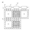
図5に示すように、本発明の第三の態様においては、一定幅の各フロート51に該一定幅よりも広い幅の水浄化部材ユニット20又は水流量調節部材ユニット10が、該各フロート51に縦方向に1列で接続され、短冊状を呈している。そしてかかる短冊状のものが左右に隣接することにより水域浄化フェンスが構成されている。ここで、左右に隣り合うユニット同士は補強枠が互いに重なるが、該ユニット同士は接続されていない。このようなユニット同士の重なりのみによっても、水域浄化フェンスとしての機能に影響を及ぼさない場合には、第三の態様は有効である。
As shown in FIG. 5, in the third aspect of the present invention, the water
第三の態様においては、フロート51にフック53が設けられ、該フロート51同士は、連結ロープ52を介して接続されている。該フック53は、水浄化部材ユニット20又は水流量調節部材ユニット10の孔に貫通し、フロート51と該ユニットを接続する。縦方向に隣接するユニット同士は、前記した第二の態様と同様に、接続手段(紐)54により接続されている。
尚、第三の態様の変形として、第三の態様における短冊状のものが、第一の態様における基材を介して各ユニットが接続されたものが挙げられる(図示せず)。
In the third aspect, the float 51 is provided with a
In addition, as a modification of the third aspect, a strip-shaped one in the third aspect may be one in which each unit is connected via the base material in the first aspect (not shown).
水域浄化フェンスの施工やユニットの交換作業における第三の態様の貢献は多大である。なぜなら、左右に隣り合うユニット同士の接続が不要であるため、潜水作業を伴わずに、各フロート51に縦方向に1列で接続され短冊状を呈するものを略ユニットの大きさに折り畳んだものを、フロート51毎に船上に積載し、これをフロート毎に順番に水域に敷設すること、また、ユニット交換時に1つの短冊状のもののみを船上に引き上げて交換作業を行い、その後水に沈めることができるからである。 The contribution of the third aspect in construction of the water purification fence and replacement of the unit is significant. Because it is not necessary to connect the left and right units adjacent to each other, the strips that are connected to the floats 51 in a single row in the vertical direction without any diving work are folded to the size of the unit. Are placed on the ship for each float 51, and this is laid in the water area in order for each float. Also, when replacing the unit, only one strip-shaped object is lifted to the ship for replacement, and then submerged in water. Because it can.
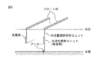
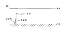
本発明に係る水域浄化フェンスは、前記したように、また、図6に示すように、水面に対し略直交する方向に展張して設置することができる。この際、図7に示すように、アンカー等を用いることにより、該水域浄化フェンスを水底に固定することもできる。図7の態様においては、フロートが水面下、水中に位置するため、船舶の通行を妨げることがなく好都合である。 As described above, as shown in FIG. 6, the water purification fence according to the present invention can be installed by extending in a direction substantially orthogonal to the water surface. At this time, as shown in FIG. 7, the water purification fence can be fixed to the bottom of the water by using an anchor or the like. In the aspect of FIG. 7, since the float is located under water and in water, it is convenient without obstructing the passage of the ship.
また、図8に示すように、該水域浄化フェンスの略平面が、水面と略平行に展張するように設置することもできる。本発明の水域浄化フェンスを、水面又は水面に近い箇所に、水面と略平行に敷設することにより、例えば、浄水場において、雨水等に含まれる有害物質を除去し、水質を好適に保つことができる。
また、図9に示すように、該水域浄化フェンスを水底に接するように敷設することもできる。図9に示す態様は、沈殿性の有害物質の除去に好適である。さらに、フロートを接続しておくことで、該水域浄化フェンスの回収が容易になる。
Moreover, as shown in FIG. 8, it can also install so that the substantially flat surface of this water purification fence may extend substantially in parallel with the water surface. By laying the water purification fence of the present invention at a location close to the water surface or substantially parallel to the water surface, for example, in water purification plants, harmful substances contained in rainwater and the like can be removed, and water quality can be suitably maintained. it can.
Further, as shown in FIG. 9, the water purification fence can be laid so as to be in contact with the water bottom. The embodiment shown in FIG. 9 is suitable for removing a precipitating harmful substance. Furthermore, by collecting the float, the water purification fence can be easily collected.
本発明に係る水域浄化フェンスは、水浄化ユニット及び水流量調節部材ユニットを、水浄化の状況に応じて適宜、選択し、それぞれ、所定数を略平面上に容易に配置又は変更することによって、水浄化領域の面積(吸着剤や微生物付着担体の量)、及び水流量調節領域の面積(透水性やろ過性)を最適化できるため、水域浄化に好適に利用可能である。 In the water purification fence according to the present invention, the water purification unit and the water flow rate adjusting member unit are appropriately selected according to the state of water purification, and the respective predetermined numbers are easily arranged or changed on a substantially plane, Since the area of the water purification area (amount of adsorbent and microbial adhesion carrier) and the area of the water flow rate adjustment area (water permeability and filterability) can be optimized, it can be suitably used for water area purification.
10 水流量調節部材ユニット
11 補強枠
12 孔(鳩目)
13 不織布等
20 水浄化部材ユニット
21 補強枠
22 孔(鳩目)
23 外袋(目の粗い網)
24 吸着剤を収容した内袋(目の細かい網)
25 吸着剤
30 水域浄化フェンスの第一の態様
31 フロート材
32 接続手段(紐)
33 基材(網・ネット)
34 接続手段(紐)
40 水域浄化フェンスの第二の態様
41 フロート材
42 ロープ
43 接続手段(紐)
44 接続手段(紐)
50 水域浄化フェンスの第三の態様
51 フロート材
52 フロート連結ロープ
53 フロート材に設けられたフック
54 接続手段(紐)
10 Water flow rate adjusting
13 Nonwoven fabric etc. 20 Water
23 Outer bag (mesh with coarse mesh)
24 Inner bag containing fine adsorbent (fine mesh)
25
33 Base material (net / net)
34 Connection means (string)
40 Second aspect of
44 Connection means (string)
50 Third aspect of water purification fence 51
Claims (10)
Priority Applications (1)
| Application Number | Priority Date | Filing Date | Title |
|---|---|---|---|
| JP2011100068A JP5773728B2 (en) | 2011-02-09 | 2011-04-27 | Water purification fence |
Applications Claiming Priority (3)
| Application Number | Priority Date | Filing Date | Title |
|---|---|---|---|
| JP2011026448 | 2011-02-09 | ||
| JP2011026448 | 2011-02-09 | ||
| JP2011100068A JP5773728B2 (en) | 2011-02-09 | 2011-04-27 | Water purification fence |
Publications (2)
| Publication Number | Publication Date |
|---|---|
| JP2012180733A true JP2012180733A (en) | 2012-09-20 |
| JP5773728B2 JP5773728B2 (en) | 2015-09-02 |
Family
ID=47012145
Family Applications (1)
| Application Number | Title | Priority Date | Filing Date |
|---|---|---|---|
| JP2011100068A Active JP5773728B2 (en) | 2011-02-09 | 2011-04-27 | Water purification fence |
Country Status (1)
| Country | Link |
|---|---|
| JP (1) | JP5773728B2 (en) |
Cited By (9)
| Publication number | Priority date | Publication date | Assignee | Title |
|---|---|---|---|---|
| JP2015152456A (en) * | 2014-02-14 | 2015-08-24 | 東洋紡株式会社 | Cesium adsorption apparatus and cesium adsorption method |
| JP2016132876A (en) * | 2015-01-16 | 2016-07-25 | アサヒ産業有限会社 | Silt fence having effect of purifying water |
| KR20180076882A (en) * | 2016-12-28 | 2018-07-06 | 한국과학기술연구원 | Oil fence with oil filtration membrane |
| JP2018180000A (en) * | 2018-07-02 | 2018-11-15 | 東洋紡株式会社 | Cesium adsorption apparatus and adsorption method |
| JP2020052057A (en) * | 2019-12-09 | 2020-04-02 | 東洋紡株式会社 | Cesium adsorption apparatus and adsorption method |
| CN113373892A (en) * | 2021-07-16 | 2021-09-10 | 绍兴市俱和环保科技有限公司 | Floating water treatment purifier |
| JP2021161723A (en) * | 2020-03-31 | 2021-10-11 | ノダック株式会社 | Boom and fish passage |
| RU216143U1 (en) * | 2022-06-20 | 2023-01-18 | Федеральное государственное бюджетное образовательное учреждение высшего образования "Волгоградский государственный технический университет" (ВолгГТУ) | Sorbent material |
| CN116747582A (en) * | 2023-08-14 | 2023-09-15 | 三亚市林业科学研究院 | Filter equipment for tidal simulated drainage |
Citations (7)
| Publication number | Priority date | Publication date | Assignee | Title |
|---|---|---|---|---|
| JPS6136414A (en) * | 1984-07-27 | 1986-02-21 | Raiondou:Kk | Water pollution preventing film |
| JPS62137312A (en) * | 1985-12-10 | 1987-06-20 | Nippon Solid Co Ltd | Pollution preventor |
| JPS6336530U (en) * | 1986-08-23 | 1988-03-09 | ||
| JPH01182408A (en) * | 1988-01-16 | 1989-07-20 | Takashina Kiyuumei Kigu Kk | Fence for preventing contaminated water from dispersing |
| JPH0399035U (en) * | 1990-01-31 | 1991-10-16 | ||
| JP2000017640A (en) * | 1998-07-01 | 2000-01-18 | Dynic Corp | Oil net with oil absorption function |
| JP2001182043A (en) * | 1999-12-28 | 2001-07-03 | Taiyo Kogyo Corp | Underwater polluted water diffusion preventing device |
-
2011
- 2011-04-27 JP JP2011100068A patent/JP5773728B2/en active Active
Patent Citations (7)
| Publication number | Priority date | Publication date | Assignee | Title |
|---|---|---|---|---|
| JPS6136414A (en) * | 1984-07-27 | 1986-02-21 | Raiondou:Kk | Water pollution preventing film |
| JPS62137312A (en) * | 1985-12-10 | 1987-06-20 | Nippon Solid Co Ltd | Pollution preventor |
| JPS6336530U (en) * | 1986-08-23 | 1988-03-09 | ||
| JPH01182408A (en) * | 1988-01-16 | 1989-07-20 | Takashina Kiyuumei Kigu Kk | Fence for preventing contaminated water from dispersing |
| JPH0399035U (en) * | 1990-01-31 | 1991-10-16 | ||
| JP2000017640A (en) * | 1998-07-01 | 2000-01-18 | Dynic Corp | Oil net with oil absorption function |
| JP2001182043A (en) * | 1999-12-28 | 2001-07-03 | Taiyo Kogyo Corp | Underwater polluted water diffusion preventing device |
Cited By (14)
| Publication number | Priority date | Publication date | Assignee | Title |
|---|---|---|---|---|
| JP2015152456A (en) * | 2014-02-14 | 2015-08-24 | 東洋紡株式会社 | Cesium adsorption apparatus and cesium adsorption method |
| JP2016132876A (en) * | 2015-01-16 | 2016-07-25 | アサヒ産業有限会社 | Silt fence having effect of purifying water |
| US10774491B2 (en) | 2016-12-28 | 2020-09-15 | Korea Institute Of Science And Technology | Oil fence with oil filtration membrane |
| KR101896614B1 (en) * | 2016-12-28 | 2018-09-07 | 한국과학기술연구원 | Oil fence with oil filtration membrane |
| KR20180076882A (en) * | 2016-12-28 | 2018-07-06 | 한국과학기술연구원 | Oil fence with oil filtration membrane |
| JP2018180000A (en) * | 2018-07-02 | 2018-11-15 | 東洋紡株式会社 | Cesium adsorption apparatus and adsorption method |
| JP2020052057A (en) * | 2019-12-09 | 2020-04-02 | 東洋紡株式会社 | Cesium adsorption apparatus and adsorption method |
| JP2021161723A (en) * | 2020-03-31 | 2021-10-11 | ノダック株式会社 | Boom and fish passage |
| JP7130691B2 (en) | 2020-03-31 | 2022-09-05 | 株式会社テクアノーツ | nets and fish ladders |
| CN113373892A (en) * | 2021-07-16 | 2021-09-10 | 绍兴市俱和环保科技有限公司 | Floating water treatment purifier |
| RU216143U1 (en) * | 2022-06-20 | 2023-01-18 | Федеральное государственное бюджетное образовательное учреждение высшего образования "Волгоградский государственный технический университет" (ВолгГТУ) | Sorbent material |
| RU216142U1 (en) * | 2022-06-20 | 2023-01-18 | Федеральное государственное бюджетное образовательное учреждение высшего образования "Волгоградский государственный технический университет" (ВолгГТУ) | Sorbent material |
| CN116747582A (en) * | 2023-08-14 | 2023-09-15 | 三亚市林业科学研究院 | Filter equipment for tidal simulated drainage |
| CN116747582B (en) * | 2023-08-14 | 2023-10-27 | 三亚市林业科学研究院 | Filter equipment for tidal simulated drainage |
Also Published As
| Publication number | Publication date |
|---|---|
| JP5773728B2 (en) | 2015-09-02 |
Similar Documents
| Publication | Publication Date | Title |
|---|---|---|
| JP5773728B2 (en) | Water purification fence | |
| EP1029132B1 (en) | Method and apparatus for controlling suspended particulates or marine life | |
| US5102261A (en) | Floating containment boom | |
| US8348549B2 (en) | Method and apparatus for absorptive boom | |
| CA2464746A1 (en) | Boom curtain with expandable pleated panels, containment boom containing the same, and use thereof | |
| KR100694606B1 (en) | Apparatus using a artificial floating island and a blocking membrane for purification of a reservoir from the river | |
| WO2003040479A9 (en) | Containment/exclusion barrier system with infuser adaptation to water intake system | |
| AU2015386029B2 (en) | Infiltration intake system for revetment wall | |
| US20120003045A1 (en) | Floating oil containment and absorbent barrier system | |
| CN212248062U (en) | Antifouling curtain suitable for river and lake environment-friendly dredging engineering | |
| JP3195852U (en) | Radioactive substance diffusion prevention device | |
| KR101067632B1 (en) | Economical interception apparatus for preventing diffusion of turbid water | |
| CN107352753B (en) | Bionic multi-combination ecological water purification weir | |
| JP2002227168A (en) | Riverbed structure and riverbed protecting method | |
| JP6491483B2 (en) | Silt fence with water purification effect | |
| KR101753901B1 (en) | Filter combined with small filtering bag, apparatus therefor and facitility thereof | |
| JP3752637B2 (en) | Oil adsorption functional oil net | |
| KR20170097598A (en) | Filter combined with small filtering bag, apparatus therefor and facitility thereof | |
| US20040197149A1 (en) | Boom system for water filtration in shallow water | |
| RU2217548C2 (en) | Obstruction-sorption beam of constant buoyancy | |
| KR101800302B1 (en) | Filter with filtering bag and pipe for maintenance thereof | |
| KR101971400B1 (en) | Structures for an artificial plant island | |
| KR20070041085A (en) | Self lock off silt protector | |
| KR20200024975A (en) | Removable Silt Protecting Apparatus | |
| KR200407925Y1 (en) | self lock off silt protector |
Legal Events
| Date | Code | Title | Description |
|---|---|---|---|
| A621 | Written request for application examination |
Free format text: JAPANESE INTERMEDIATE CODE: A621 Effective date: 20140424 |
|
| A977 | Report on retrieval |
Free format text: JAPANESE INTERMEDIATE CODE: A971007 Effective date: 20141218 |
|
| A131 | Notification of reasons for refusal |
Free format text: JAPANESE INTERMEDIATE CODE: A131 Effective date: 20150106 |
|
| A521 | Request for written amendment filed |
Free format text: JAPANESE INTERMEDIATE CODE: A523 Effective date: 20150309 |
|
| TRDD | Decision of grant or rejection written | ||
| A01 | Written decision to grant a patent or to grant a registration (utility model) |
Free format text: JAPANESE INTERMEDIATE CODE: A01 Effective date: 20150602 |
|
| A61 | First payment of annual fees (during grant procedure) |
Free format text: JAPANESE INTERMEDIATE CODE: A61 Effective date: 20150630 |
|
| R150 | Certificate of patent or registration of utility model |
Ref document number: 5773728 Country of ref document: JP Free format text: JAPANESE INTERMEDIATE CODE: R150 |
|
| S111 | Request for change of ownership or part of ownership |
Free format text: JAPANESE INTERMEDIATE CODE: R313115 |
|
| R350 | Written notification of registration of transfer |
Free format text: JAPANESE INTERMEDIATE CODE: R350 |
|
| R250 | Receipt of annual fees |
Free format text: JAPANESE INTERMEDIATE CODE: R250 |
|
| R250 | Receipt of annual fees |
Free format text: JAPANESE INTERMEDIATE CODE: R250 |
|
| R250 | Receipt of annual fees |
Free format text: JAPANESE INTERMEDIATE CODE: R250 |
|
| R250 | Receipt of annual fees |
Free format text: JAPANESE INTERMEDIATE CODE: R250 |
|
| R250 | Receipt of annual fees |
Free format text: JAPANESE INTERMEDIATE CODE: R250 |
|
| S111 | Request for change of ownership or part of ownership |
Free format text: JAPANESE INTERMEDIATE CODE: R313117 |
|
| R350 | Written notification of registration of transfer |
Free format text: JAPANESE INTERMEDIATE CODE: R350 |
|
| R250 | Receipt of annual fees |
Free format text: JAPANESE INTERMEDIATE CODE: R250 |