JP2012179874A - Decorative glass container and method for manufacturing the same - Google Patents
Decorative glass container and method for manufacturing the same Download PDFInfo
- Publication number
- JP2012179874A JP2012179874A JP2011045827A JP2011045827A JP2012179874A JP 2012179874 A JP2012179874 A JP 2012179874A JP 2011045827 A JP2011045827 A JP 2011045827A JP 2011045827 A JP2011045827 A JP 2011045827A JP 2012179874 A JP2012179874 A JP 2012179874A
- Authority
- JP
- Japan
- Prior art keywords
- layer
- decorative
- inkjet
- glass container
- glass wall
- Prior art date
- Legal status (The legal status is an assumption and is not a legal conclusion. Google has not performed a legal analysis and makes no representation as to the accuracy of the status listed.)
- Granted
Links
Images


Classifications
-
- B—PERFORMING OPERATIONS; TRANSPORTING
- B41—PRINTING; LINING MACHINES; TYPEWRITERS; STAMPS
- B41J—TYPEWRITERS; SELECTIVE PRINTING MECHANISMS, i.e. MECHANISMS PRINTING OTHERWISE THAN FROM A FORME; CORRECTION OF TYPOGRAPHICAL ERRORS
- B41J3/00—Typewriters or selective printing or marking mechanisms characterised by the purpose for which they are constructed
- B41J3/407—Typewriters or selective printing or marking mechanisms characterised by the purpose for which they are constructed for marking on special material
- B41J3/4073—Printing on three-dimensional objects not being in sheet or web form, e.g. spherical or cubic objects
Abstract
Description
本発明は、装飾ガラス容器およびそのような装飾ガラス容器の製造方法に関する。特に、インクジェット法によって、紫外線硬化樹脂から形成されたインクジェット装飾層を背面側から視認する構成の装飾ガラス容器、およびそのようなインクジェット装飾層を有する装飾ガラス容器の製造方法に関する。 The present invention relates to a decorative glass container and a method for producing such a decorative glass container. In particular, the present invention relates to a decorative glass container configured to visually recognize an inkjet decorative layer formed from an ultraviolet curable resin from the back side by an inkjet method, and a method for manufacturing a decorative glass container having such an inkjet decorative layer.
従来、インクジェット装飾層を備えた装飾ガラス容器の製造方法として、各種方法が提案されている。
例えば、熱硬化性樹脂等を用いたホットスタンプ法によって、ガラス容器上に、パターン化された蒸着層を形成する方法が提案されている(特許文献1参照)。
より具体的には、図8(a)に示すように、ガラス容器100を準備する。次いで、図8(b)に示すように、ガラス容器100上に、スクリーン印刷により、熱硬化性樹脂102をパターン印刷した後、所定条件で加熱処理を行い、熱硬化性樹脂102を半硬化状態とする。
次いで、図8(c)に示すように、ガラス容器100に対して、蒸着層104を有するホットスタンプ用転写材(図示せず)を積層し、加熱弾性体等を用いて、半硬化の熱硬化性樹脂102に対して均一に押し付ける。
次いで、図8(d)に示すように、ホットスタンプ用転写材を剥離して、部分的に蒸着層104を転写し、半硬化の熱硬化性樹脂102に対応して、所定パターンを有する蒸着層104aを形成する。
最後に、図8(e)に示すように、外部加熱装置106を用いて、さらなる加熱処理を行って、完全硬化させた熱硬化性樹脂102aとすることにより、所定パターンを有するホットスタンプ蒸着層104aを強固に備えた装飾ガラス容器100とするものである。
Conventionally, various methods have been proposed as a method for manufacturing a decorative glass container provided with an inkjet decorative layer.
For example, a method of forming a patterned vapor deposition layer on a glass container by a hot stamp method using a thermosetting resin or the like has been proposed (see Patent Document 1).
More specifically, a
Next, as shown in FIG. 8C, a hot stamping transfer material (not shown) having a
Next, as shown in FIG. 8D, the transfer material for hot stamping is peeled off, the
Finally, as shown in FIG. 8 (e), further heat treatment is performed using an
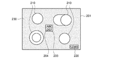
一方、精密な印刷画像を形成すべく、ガラス基材等の上に、非デジタル印刷技術を用いて既に塗工された装飾物等に加えて、インクジェット法等のデジタル印刷技術を用いて装飾することが提案されている(特許文献2参照)。
より具体的には、図9にガラスセラミックス製クッキングトップ用パネルの適用例を示すが、非デジタル印刷技術を用いて塗工された塗装領域230をほぼ全面に有するガラス物品としてのクッキングトップ用パネル201において、デジタル印刷技術で製造された所定印刷領域203、印刷画像(製造者名)204、調理領域の表示210、および製品番号表示220を有するガラス物品としてのクッキングトップ用パネル201である。
On the other hand, in order to form a precise printed image, it is decorated on a glass substrate or the like using a digital printing technique such as an ink-jet method in addition to a decoration already applied using a non-digital printing technique. Has been proposed (see Patent Document 2).
More specifically, FIG. 9 shows an application example of a glass ceramics cooking top panel, but the cooking top panel as a glass article having a
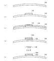
さらに、インクジェット記録可能な装飾シートが知られており、このような装飾シートを、ガラス材料等に貼付することが提案されている(特許文献3参照)。
より具体的には、図10に示すように、支持体301の片面に、着色フィルムを含有する接着樹脂層302および透明紙303を順次積層してなる装飾シート305の表面に、インクジェットインク受理層304をさらに積層してなるインクジェット記録可能な装飾シート306である。
Furthermore, a decorative sheet capable of inkjet recording is known, and it has been proposed to attach such a decorative sheet to a glass material or the like (see Patent Document 3).
More specifically, as shown in FIG. 10, an inkjet ink receiving layer is provided on the surface of a
しかしながら、特許文献1に開示された装飾ガラス容器100の製造方法によれば、高級感のある金文字や金装飾等が得られるものの、写真様な精密模様を反映したインクジェット装飾層を形成することはできなかった。
However, according to the method of manufacturing the
また、特許文献2に開示されたガラス物品としては、クッキングトップ用パネル201等が主であって、背面視認性を何ら考慮していないという問題が見られた。
その上、ガラス物品として、注射用アンプル等が開示されているものの、かかる注射用アンプル等は、塗装面が平坦でないことから、剥離方向に応力が集中し、インクジェット法等によって形成したインクジェット装飾層が、ガラス基板から容易に剥離してしまい、耐久性に乏しいという問題が見られた。
Moreover, as a glass article disclosed by
In addition, although ampules for injection and the like are disclosed as glass articles, such an ampule for injection and the like has a coating surface that is not flat, so stress is concentrated in the peeling direction, and an inkjet decorative layer formed by an inkjet method or the like However, it peeled off easily from the glass substrate, and there was a problem that the durability was poor.
さらに、特許文献3に開示された装飾シート306によれば、接着樹脂層302および透明紙303を介して、インクジェットインク受理層304をガラス基材に貼付する必要があるため、接着樹脂層302等が光屈折現象を生じさせたり、光吸収したりして、ガラス基材の前面側から背面側を視認した場合に、インクジェットインク受理層304の視認性が乏しいという問題が見られた。
その上、装飾シート306における接着樹脂層302が、ガラス表面から移行しやすいアルカリ成分や外部紫外線等に起因して、経時劣化すると、ガラス基材からインクジェットインク受理層304を含む装飾シート306が剥がれやすくなって、ガラス基材と、接着樹脂層302との間に、気泡が生じやすくなり、結果として、背面視認性がさらに低下するという問題が見られた。
Furthermore, according to the
In addition, when the
そこで、本発明の発明者らは、鋭意研究した結果、所定形態のガラス容器を準備するとともに、所定ガラス容器の所定位置に、紫外線照射によって、所定解像度以上のインクジェット装飾層を設けることによって、装飾性、形成性、耐久性、さらには視認性等に優れた装飾ガラス容器が得られることを見出し、本発明を完成させたものである。
すなわち、所定ガラス容器の所定位置に、紫外線硬化させたインクジェット装飾層を設けるとともに、所定ガラス容器(前面ガラス壁および背面ガラス壁)を介して、インクジェット装飾層を背面視認することによって、装飾性や視認性等に優れた装飾ガラス容器、およびそのような装飾ガラス容器の効率的な製造方法を提供することを目的とする。
Therefore, the inventors of the present invention, as a result of earnest research, prepared a glass container of a predetermined form, and provided an inkjet decoration layer having a predetermined resolution or higher by ultraviolet irradiation at a predetermined position of the predetermined glass container. The present invention has been completed by finding that a decorative glass container excellent in properties, formability, durability, and visibility can be obtained.
In other words, an ultraviolet-cured inkjet decoration layer is provided at a predetermined position of a predetermined glass container, and the decorativeness or the like can be obtained by visually recognizing the inkjet decoration layer through the predetermined glass container (front glass wall and rear glass wall). An object of the present invention is to provide a decorative glass container excellent in visibility and the like, and an efficient method for producing such a decorative glass container.
本発明によれば、所定間隔で平行配置してなる前面ガラス壁と、背面ガラス壁と、を有するガラス容器の背面側にインクジェット装飾層を設け、前面ガラス壁および背面ガラス壁を介して、インクジェット装飾層を視認する構成の装飾ガラス容器であって、インクジェット装飾層が、インクジェット法により、紫外線硬化型インクを用いて形成してあることを特徴とする装飾ガラス容器である。 According to the present invention, an inkjet decoration layer is provided on the back side of a glass container having a front glass wall and a rear glass wall that are arranged in parallel at a predetermined interval, and an inkjet is provided via the front glass wall and the rear glass wall. A decorative glass container configured to visually recognize a decorative layer, wherein the inkjet decorative layer is formed using an ultraviolet curable ink by an inkjet method.
このような装飾ガラス容器であれば、背面ガラス壁の背面側に直接的に形成された写真模様等を有するインクジェット装飾層(例えば、解像度400dpi以上、好ましくは600〜1000dpi)を、前面ガラス壁および背面ガラス壁を介して、前面側から視認することができ、良好な装飾性や背面視認性を得ることができる。
また、インクジェット法により、背面ガラス壁に対して、紫外線硬化型インクを精度良く塗布して、それに対して、紫外線を照射することにより、極めて迅速にインクジェット装飾層を形成することができる。
その上、平坦な背面ガラス壁に対して、直接的に所定のインクジェット装飾層が形成してあることから、良好な密着性が得られるとともに、ひいては、優れた耐久性や背面視認性を得ることができる。
In such a decorative glass container, an inkjet decorative layer (for example, resolution of 400 dpi or more, preferably 600 to 1000 dpi) having a photographic pattern or the like directly formed on the back side of the back glass wall is provided on the front glass wall and It can be visually recognized from the front side through the back glass wall, and good decorativeness and backside visibility can be obtained.
Moreover, an inkjet decoration layer can be formed very rapidly by applying an ultraviolet curable ink to the back glass wall with high accuracy by an inkjet method and irradiating ultraviolet rays on it.
In addition, since a predetermined inkjet decoration layer is directly formed on the flat back glass wall, good adhesion can be obtained and, in turn, excellent durability and back visibility can be obtained. Can do.
また、本発明の装飾ガラス容器を構成するにあたり、背面ガラス壁の少なくとも容器外側に、シランカップリング剤処理またはケイ酸化炎処理が施してあることが好ましい。
このような表面処理が施してあることにより、背面ガラス壁に対して、さらに良好な密着性が得られるとともに、ひいては、優れた耐久性や背面視認性を得ることができる。
Further, in constituting the decorative glass container of the present invention, it is preferable that a silane coupling agent treatment or a silicic acid flame treatment is performed on at least the outer side of the back glass wall.
By performing such a surface treatment, it is possible to obtain better adhesion to the rear glass wall and, in turn, to obtain excellent durability and rear visibility.
また、本発明の装飾ガラス容器を構成するにあたり、インクジェット装飾層の外側であって、かつ、背面ガラス壁とは反対側に、光遮蔽層が設けてあることが好ましい。
このように構成することにより、インクジェット装飾層における発色性が良好になって、さらに良好な装飾性や背面視認性を得ることができる。
その上、光遮蔽層がインクジェット装飾層の保護層として機能することから、インクジェット装飾層の耐久性をさらに良好なものとすることができる。
Further, in configuring the decorative glass container of the present invention, it is preferable that a light shielding layer is provided on the outer side of the inkjet decorative layer and on the side opposite to the rear glass wall.
By comprising in this way, the color development property in an inkjet decoration layer becomes favorable, and more favorable decorativeness and back surface visibility can be obtained.
In addition, since the light shielding layer functions as a protective layer for the inkjet decoration layer, the durability of the inkjet decoration layer can be further improved.
また、本発明の装飾ガラス容器を構成するにあたり、インクジェット装飾層の外側であって、かつ、背面ガラス壁とは反対側に、インクジェット装飾層を保護するための熱硬化性樹脂層または光硬化性樹脂層が設けてあることが好ましい。
このように構成することにより、装飾ガラス容器全体として、装飾性が向上するとともに、さらに良好な耐久性を得ることができる。
Further, in constituting the decorative glass container of the present invention, a thermosetting resin layer or a photocurable resin for protecting the inkjet decorative layer on the outer side of the inkjet decorative layer and on the side opposite to the back glass wall. A resin layer is preferably provided.
By comprising in this way, while the decoration property improves as a whole decorative glass container, further favorable durability can be obtained.
また、本発明の装飾ガラス容器を構成するにあたり、背面ガラス壁の容器外側に設けたインクジェット装飾層を第1の装飾層としたときに、前面ガラス壁の外側に、第2の装飾層を設けるとともに、当該第2の装飾層が、ホットスタンプ層、紫外線硬化性樹脂層、熱硬化性樹脂層、および熱可塑性樹脂層の少なくとも一層であることが好ましい。
このように構成することにより、装飾ガラス容器全体として、装飾性や背面視認性をさらに向上させることができる。
Further, in configuring the decorative glass container of the present invention, when the inkjet decorative layer provided outside the container on the back glass wall is used as the first decorative layer, the second decorative layer is provided outside the front glass wall. At the same time, the second decorative layer is preferably at least one of a hot stamp layer, an ultraviolet curable resin layer, a thermosetting resin layer, and a thermoplastic resin layer.
By comprising in this way, a decoration property and back surface visibility can further be improved as the whole decoration glass container.
また、本発明の別の態様は、所定間隔で平行配置してなる前面ガラス壁と、背面ガラス壁と、を有するガラス容器の所定位置にインクジェット装飾層を設け、前面ガラス壁および背面ガラス壁を介して、インクジェット装飾層を視認する構成の装飾ガラス容器の製造方法であって、下記工程(1)〜(3)を含むことを特徴とする装飾ガラス容器の製造方法である。
(1)所定間隔で平行配置してなる前面ガラス壁と、背面ガラス壁と、を有するガラス容器を準備する工程
(2)背面ガラス壁の容器外側に、インクジェット法により、紫外線硬化型インクを塗布する工程
(3)紫外線照射することにより、紫外線硬化型インクを硬化させて、インクジェット層とする工程
In another aspect of the present invention, an inkjet decorative layer is provided at a predetermined position of a glass container having a front glass wall and a rear glass wall that are arranged in parallel at a predetermined interval, and the front glass wall and the rear glass wall are provided. A method for manufacturing a decorative glass container having a structure for visually recognizing an inkjet decorative layer, comprising the following steps (1) to (3).
(1) A step of preparing a glass container having a front glass wall and a rear glass wall arranged in parallel at a predetermined interval (2) An ultraviolet curable ink is applied to the outside of the rear glass wall by an ink jet method Step (3) Step of curing the ultraviolet curable ink by irradiating with ultraviolet rays to form an ink jet layer
このように実施することにより、背面ガラス壁に直接的に形成された写真様の模様等を有するインクジェット装飾層を、前面ガラス壁および背面ガラス壁を介して、視認することができ、良好な装飾性や背面視認性を有する装飾ガラス容器を効率的に得ることができる。
また、インクジェット法により、背面ガラス壁に対して、紫外線硬化型インクを塗布して、それに対して、紫外線を照射することにより、極めて迅速にインクジェット装飾層を形成することができる。
その上、平坦な背面ガラス壁に対して、各種フィルムや接着剤等を介さず、直接的に所定のインクジェット装飾層が形成してあることから、良好な密着性が得られるとともに、ひいては、優れた耐久性や背面視認性を得ることができる。
By carrying out in this way, an ink-jet decorative layer having a photographic pattern or the like directly formed on the back glass wall can be visually recognized through the front glass wall and the back glass wall, and a good decoration A decorative glass container having high visibility and backside visibility can be obtained efficiently.
In addition, an inkjet decoration layer can be formed very quickly by applying an ultraviolet curable ink to the back glass wall by an inkjet method and irradiating it with ultraviolet rays.
In addition, since a predetermined inkjet decoration layer is formed directly on the flat back glass wall without using various films or adhesives, it is possible to obtain good adhesion and, in turn, excellent Durability and rear visibility can be obtained.
また、本発明の装飾ガラス容器の製造方法を実施するにあたり、背面ガラス壁の少なくとも容器外側に、シランカップリング剤処理またはケイ酸化炎処理を施す工程を設けることが好ましい。
このような表面処理を施すことにより、背面ガラス壁に対して、インクジェット装飾層が良好な密着性が示すとともに、ひいては、優れた耐久性を得ることができる。
Moreover, when implementing the manufacturing method of the decoration glass container of this invention, it is preferable to provide the process of performing a silane coupling agent process or a silicic acid flame process at least on the container outer side of a back glass wall.
By performing such a surface treatment, the ink-jet decorative layer exhibits good adhesion to the back glass wall, and thus excellent durability can be obtained.
また、本発明の装飾ガラス容器の製造方法を実施するにあたり、インクジェット装飾層の外側であって、かつ、背面ガラス壁とは反対側に、光遮蔽層を設ける工程を含むことが好ましい。
このように実施することにより、インクジェット装飾層における発色性が顕著になって、さらに良好な装飾性や背面視認性を有する装飾ガラス容器を効率的に得ることができる。
その上、光遮蔽層がインクジェット装飾層の保護層としても機能することから、インクジェット装飾層における耐久性や密着性をさらに良好なものとすることができる。
Moreover, when implementing the manufacturing method of the decoration glass container of this invention, it is preferable to include the process of providing a light-shielding layer in the outer side of an inkjet decoration layer and on the opposite side to a back glass wall.
By carrying out in this way, the color developability in the inkjet decorative layer becomes remarkable, and a decorative glass container having better decorative properties and rear visibility can be efficiently obtained.
In addition, since the light shielding layer also functions as a protective layer for the inkjet decoration layer, the durability and adhesion of the inkjet decoration layer can be further improved.
[第1の実施形態]
第1の実施形態は、所定間隔で平行配置してなる前面ガラス壁と、背面ガラス壁と、を有するガラス容器の背面側にインクジェット装飾層を設け、前面ガラス壁および背面ガラス壁を介して、インクジェット装飾層を視認する構成の装飾ガラス容器であって、インクジェット装飾層が、インクジェット法により、紫外線硬化型インクを用いて形成してあることを特徴とする装飾ガラス容器である。
すなわち、第1の実施形態は、図1〜図5に例示する態様の装飾ガラス容器1a〜5b、あるいは図6に示す態様の装飾ガラス容器6a〜6dである。
以下、適宜図面を参照しながら、第1の実施形態の装飾ガラス容器について、具体的に説明する。
[First Embodiment]
In the first embodiment, an inkjet decorative layer is provided on the back side of a glass container having a front glass wall and a back glass wall that are arranged in parallel at a predetermined interval, and the front glass wall and the back glass wall are interposed, A decorative glass container configured to visually recognize an inkjet decorative layer, wherein the inkjet decorative layer is formed using an ultraviolet curable ink by an inkjet method.
That is, 1st Embodiment is the
Hereinafter, the decorative glass container of the first embodiment will be specifically described with reference to the drawings as appropriate.
1.ガラス容器
(1)形状
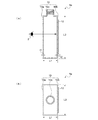
図1(a)等に示すガラス容器10は、所定間隔(L1)で平行配置してなる前面ガラス壁10aと、背面ガラス壁10bと、を有することを特徴とする。
この理由は、このような構成であれば、写真様の模様等を有するインクジェット装飾層(インクジェット装飾層と称する場合がある。)を、インクジェット法および紫外線照射により、背面ガラス壁に対して、直接的かつ精度良く、しかも迅速に形成することができるためである。
1. Glass Container (1) Shape A
This is because, with such a configuration, an inkjet decoration layer (sometimes referred to as an inkjet decoration layer) having a photographic pattern or the like is directly applied to the back glass wall by an inkjet method and ultraviolet irradiation. This is because it can be formed quickly, accurately and accurately.
また、このようなガラス容器であれば、前面ガラス壁および背面ガラス壁を介して、インクジェット装飾層を視認することができるためである。
すなわち、従来の装飾シートのように、PETフィルム上に形成したインクジェット装飾層を、接着剤層を介して、ガラス容器の表面に貼付する態様にあっては、ガラス壁以外に、PETフィルムや接着剤層を介して、インクジェット装飾層を視認することから、鮮明度が著しく低下するためである。
Moreover, it is because such an ink-jet decoration layer can be visually recognized through a front glass wall and a back glass wall if it is such a glass container.
That is, in a mode in which an inkjet decoration layer formed on a PET film is pasted on the surface of a glass container via an adhesive layer as in a conventional decoration sheet, in addition to a glass wall, This is because the inkjet decoration layer is visually recognized through the agent layer, so that the sharpness is remarkably lowered.
その上、平坦な背面ガラス壁に対して、直接的に所定のインクジェット装飾層が形成してあることから、良好な密着性や形成性が得られるとともに、ひいては、優れた耐久性や背面視認性を得ることができるためである。
すなわち、従来の断面が円形等のガラス容器に対して、インクジェット法によって、所定大きさのインクジェット装飾層を形成しようとしても、インクジェット装飾層の周辺部分に付着するインク量が大きく変わり、その結果、精度良く、かつ均一にインクジェット装飾層を形成することが困難であるためである。
In addition, since a predetermined inkjet decoration layer is directly formed on the flat back glass wall, good adhesion and formability can be obtained, and as a result, excellent durability and back view visibility. It is because it can be obtained.
That is, even if an ink-jet decoration layer having a predetermined size is formed on a conventional glass container having a circular cross section by the ink-jet method, the amount of ink adhering to the peripheral portion of the ink-jet decoration layer is greatly changed. This is because it is difficult to form the inkjet decoration layer with high accuracy and uniformity.
したがって、このような平行配置してなる前面ガラス壁と、背面ガラス壁と、を有するガラス容器として、図1(a)〜(b)に示すように、全体矩形状のガラスビン1aや、図6(a)〜(d)に示すように、前面ガラス壁10aおよび背面ガラス壁10bの正面形状が、それぞれ円形、りんご形状、三角形、逆三角形等であって、かつ、両側面は長方形状であるガラス容器6a〜6dが挙げられる。
Therefore, as a glass container having such a front glass wall and a rear glass wall that are arranged in parallel, as shown in FIGS. 1 (a) and 1 (b), an overall
(2)所定間隔
ガラス容器は、図1(a)に示すように、前面ガラス壁10aと、背面ガラス壁10bと、を有することを特徴とするとともに、これらの間の距離、すなわち、所定間隔(L1)を、通常、5〜30mmの範囲内の値とすることが好ましい。
この理由は、かかる所定間隔が5mm未満の値になると、安定的にガラス容器を製造することが困難となったり、内部容積が過度に小さくなって、ガラス容器の使い勝手が著しく低下したりする場合があるためである。
一方、かかる所定間隔が30mmを超えると、インクジェット装飾層の背面視認性が著しく低下したり、インクジェット装飾層を安定的に形成することが困難となったりする場合があるためである。
したがって、前面ガラス壁と、背面ガラス壁との所定間隔(L1)を8〜25mmの範囲内の値とすることが好ましく、10〜20mmの範囲内の値とすることがさらに好ましい。
なお、図1(a)に示すガラス容器1aの所定間隔(L1)以外の寸法についても、かかる所定間隔(L1)やガラス容器の用途、あるいはガラス容器の強度等を考慮して定めることが好ましい。
より具体的に、図1(a)に示すガラス容器1aの高さ(L2)を、通常、20〜200mmの範囲内の値とすることが好ましく、ガラス容器1aの幅(L3)を通常、20〜80mmの範囲内の値とすることが好ましい。
(2) Predetermined spacing As shown in FIG. 1A, the glass container has a
The reason for this is that when the predetermined interval is less than 5 mm, it is difficult to stably manufacture the glass container, or the internal volume becomes excessively small, and the usability of the glass container is significantly reduced. Because there is.
On the other hand, when the predetermined interval exceeds 30 mm, the back surface visibility of the ink jet decoration layer may be remarkably lowered, or it may be difficult to stably form the ink jet decoration layer.
Therefore, the predetermined distance (L1) between the front glass wall and the rear glass wall is preferably set to a value in the range of 8 to 25 mm, and more preferably set to a value in the range of 10 to 20 mm.
It should be noted that dimensions other than the predetermined interval (L1) of the
More specifically, the height (L2) of the
(3)厚さ
図1(a)に示す前面ガラス壁10aおよび背面ガラス壁10bの厚さ(t1、t2)については、それぞれガラス容器の機械的強度や製造安定性、あるいはインクジェット装飾層の背面視認性等を考慮して定めることができるが、通常、0.2〜5mmの範囲内の値とすることが好ましい。
この理由は、かかる厚さが0.2mm未満の値になると、ガラス容器の機械的強度が著しく低下したり、安定的にガラス容器を製造することが困難となったりする場合があるためである。
一方、かかる厚さが5mmを超えると、インクジェット装飾層の背面視認性が著しく低下したり、安定的にガラス容器を製造することが困難となったりする場合があるためである。
したがって、前面ガラス壁および背面ガラス壁の厚さを0.5〜3mmの範囲内の値とすることが好ましく、0.8〜2mmの範囲内の値とすることがさらに好ましい。
(3) Thickness Regarding the thickness (t1, t2) of the
This is because when the thickness is less than 0.2 mm, the mechanical strength of the glass container may be significantly reduced or it may be difficult to stably manufacture the glass container. .
On the other hand, if the thickness exceeds 5 mm, the back surface visibility of the inkjet decoration layer may be significantly reduced, or it may be difficult to stably produce a glass container.
Therefore, the thickness of the front glass wall and the rear glass wall is preferably set to a value within the range of 0.5 to 3 mm, and more preferably set to a value within the range of 0.8 to 2 mm.
(4)着色性
また、使用するガラス容器として、インクジェット装飾層を視認するためには無色透明ガラスを用いることが好ましいが、用途によっては、着色透明ガラスや着色半透明ガラスを用いることも好ましい。
この理由は、着色透明ガラスや着色半透明ガラスを用いることにより、内容物の識別性を過度に低下させることなく、所定場所に設けたインクジェット装飾層につき、レインボーカラー、玉虫色、パールルミネッセンス(真珠光沢)、鱗粉模様等の複雑な色具合を加味して認識できるためである。
(4) Colorability As the glass container to be used, it is preferable to use colorless transparent glass for visually recognizing the ink jet decorative layer, but depending on applications, it is also preferable to use colored transparent glass or colored translucent glass.
The reason for this is that by using colored transparent glass or colored translucent glass, the rainbow color, iridescent color, pearl luminescence (pearly luster) can be applied to the ink-jet decorative layer provided at a predetermined location without excessively degrading the contents. ), Because it can be recognized in consideration of complex color conditions such as scale patterns.
(5)表面処理
また、図5(a)〜(b)に示すように、背面ガラス壁10bの容器外側に該当する箇所に、表面処理として、シランカップリング剤層13またはケイ酸化炎処理層15が、それぞれ形成してあることが好ましい。
この理由は、このようなプライマー的な表面処理が施してあることにより、背面ガラス壁に対して、さらに良好な密着性が得られるとともに、ひいては、優れた耐久性や背面視認性を得ることができるためである。
より具体的には、シランカップリング剤処理の場合には、図5(a)に示すように、比較的均一な薄膜層を、シランカップリング剤層13として形成することによって、背面ガラス壁10bと、インクジェット装飾層12との間の密着性を向上させることができる。
一方、ケイ酸化炎処理の場合には、図5(b)に示すように、活性水素を有するナノメーターレベルのシリカからなる不連続薄膜層として、ケイ酸化炎処理層15を形成し、背面ガラス壁10bと、インクジェット装飾層12との間の密着性を向上させることができる。
(5) Surface treatment Moreover, as shown to Fig.5 (a)-(b), in the location applicable to the container outer side of the
This is because such a primer-like surface treatment gives better adhesion to the rear glass wall and, in turn, excellent durability and rear visibility. This is because it can.
More specifically, in the case of silane coupling agent treatment, as shown in FIG. 5 (a), a relatively uniform thin film layer is formed as the silane
On the other hand, in the case of silicic acid flame treatment, as shown in FIG. 5 (b), a silicic acid
ここで、シランカップリング剤処理に際して、好ましいシランカップリング剤としては、例えば、3−アミノプロピルトリエトキシシラン、3−メルカプトプロピルトリエトキシシラン、3−グリシドキシプロピルトリエトキシシラン、3−アミノプロピルトリメトキシシラン、3−メルカプトプロピルトリメトキシシラン、3−グリシドキシプロピルトリメトキシシラン等の一種単独または二種以上の組み合わせが挙げられる。
そして、かかるシランカップリング剤を、水またはアルコール化合物等に溶解させて、希釈した状態で、背面ガラス壁の容器外側に該当する箇所に、刷毛塗りしたり、スプレー塗布したり、ロール塗布したりすることによって、適用することができる。
Here, in the silane coupling agent treatment, preferred silane coupling agents include, for example, 3-aminopropyltriethoxysilane, 3-mercaptopropyltriethoxysilane, 3-glycidoxypropyltriethoxysilane, 3-aminopropyl. One kind alone or a combination of two or more kinds such as trimethoxysilane, 3-mercaptopropyltrimethoxysilane, and 3-glycidoxypropyltrimethoxysilane may be mentioned.
Then, such a silane coupling agent is dissolved in water or an alcohol compound and diluted with a brush, sprayed, or roll-coated on a portion corresponding to the outside of the container on the back glass wall. Can be applied.
一方、ケイ酸化炎処理の場合には、沸点が20〜120℃の範囲であるケイ素含有化合物を含む燃料ガスに由来した火炎(ケイ酸化炎)を、ガラス容器の表面に対して、例えば、1〜60秒間、全面的または部分的に吹き付けることによって、表面の濡れ指数を70dyn/cm以上の値とすることができる。
そして、ケイ酸化炎に用いるケイ素含有化合物としては、テトラメチルシラン、ヘキサメチルジシラザン、ビニルトリメトキシシラン、ビニルトリエトキシシラン、トリフルオロプロピルトリメトキシシラン、トリフルオロプロピルトリクロロシラン、3−アミノプロピルトリメトキシシラン、3−アミノプロピルトリエトキシシラン、および3−クロロプロピルトリメトキシシランの一種単独または二種以上の混合物であることが好ましい。
On the other hand, in the case of silicic acid flame treatment, a flame (silicic acid flame) derived from a fuel gas containing a silicon-containing compound having a boiling point in the range of 20 to 120 ° C. is applied to the surface of the glass container, for example, 1 By spraying the entire surface or partially for ˜60 seconds, the wetting index of the surface can be set to a value of 70 dyn / cm or more.
The silicon-containing compounds used in the silicic acid flame include tetramethylsilane, hexamethyldisilazane, vinyltrimethoxysilane, vinyltriethoxysilane, trifluoropropyltrimethoxysilane, trifluoropropyltrichlorosilane, 3-aminopropyltrichlorosilane. One kind of methoxysilane, 3-aminopropyltriethoxysilane, and 3-chloropropyltrimethoxysilane is used alone, or a mixture of two or more kinds.
(6)表面粗さ
また、図4に示すように、ガラス容器10の表面に、微細な表面凹凸10dを設けることが好ましい。
この理由は、かかる表面凹凸を設けることによって、インクジェット装飾層との間で接触面積が大きくなって、ガラス容器と、インクジェット装飾層との間の密着性が向上するためである。
したがって、表面凹凸の表面粗さ(Rz)を0.1〜5μmの範囲内の値とすることが好ましく、0.5〜3μmの範囲内の値とすることがより好ましく、0.8〜2μmの範囲内の値とすることがさらに好ましい。
なお、かかる表面粗さ(Rz)は、ブラスト処理やケミカル研磨処理等によっても調整することができるが、レーザー加工を採用し、レーザー出力や加工時間等の調整によって、かかる表面粗さ(Rz)を調整することができる。
(6) Surface Roughness As shown in FIG. 4, it is preferable to provide
The reason for this is that providing such surface irregularities increases the contact area between the ink jet decorative layer and improves the adhesion between the glass container and the ink jet decorative layer.
Accordingly, the surface roughness (Rz) of the surface irregularities is preferably set to a value in the range of 0.1 to 5 μm, more preferably set to a value in the range of 0.5 to 3 μm, and 0.8 to 2 μm. It is more preferable to set the value within the range.
The surface roughness (Rz) can be adjusted by blasting, chemical polishing, or the like, but adopting laser processing, the surface roughness (Rz) can be adjusted by adjusting the laser output or processing time. Can be adjusted.
2.インクジェット装飾層
また、図1等に示すように、ガラス容器10の所定場所に、インクジェット装飾層12を設けることを特徴とする。
この理由は、文字、図形、記号等からなるパターン化されたインクジェット装飾層を、ガラス容器10における背面ガラス壁10bの所定場所に対して、直接的に設けることによって、着色したり、模様を施したりして、装飾ガラス容器における装飾性をさらに向上させることができるためである。
すなわち、粘接着剤層等を介して、インクジェット装飾層を形成しないことから、粘接着剤層等に起因した光吸収や光散乱の影響を排除することができる。
その上、粘接着剤層等が劣化した場合における、インクジェット装飾層の浮きに起因した空気侵入の影響を排除することができる。
2. Inkjet decoration layer Moreover, as shown in FIG. 1 etc., the
The reason for this is that a patterned ink-jet decorative layer made up of characters, figures, symbols, etc. is colored or patterned by providing it directly to a predetermined place on the
That is, since the inkjet decoration layer is not formed via the adhesive layer or the like, the influence of light absorption or light scattering caused by the adhesive layer or the like can be eliminated.
In addition, it is possible to eliminate the influence of air intrusion caused by the floating of the inkjet decoration layer when the adhesive layer or the like is deteriorated.
また、インクジェット装飾層は、インクジェット法を用いて、紫外線硬化性樹脂から構成されることを特徴としている。
したがって、例えば、インクジェット装飾層の全体量(100重量%)に対して、重量平均分子量が1000〜10000のアクリレートオリゴマーが2〜10重量%、重量平均分子量が1000未満のアクリレートモノマーが10〜40重量%、重量平均分子量が5万以上のアクリル樹脂が3〜15重量%、光重合開始剤が0.1〜3重量%、着色剤が0.1〜3重量%、残量が有機溶剤である紫外線硬化型塗布液の配合組成とすることが好ましい。
そして、必要に応じて、インクジェット装飾層中に、相溶化剤、難燃剤、充填剤(ガラス繊維、炭素繊維、金属フィラー等)、安定剤(脂肪酸金属塩、酸化防止剤等)、滑剤、分散剤、発泡剤、抗菌剤等を含むことも好ましい。
In addition, the ink jet decoration layer is characterized by being made of an ultraviolet curable resin using an ink jet method.
Therefore, for example, 2 to 10% by weight of an acrylate oligomer having a weight average molecular weight of 1000 to 10000 and 10 to 40% by weight of an acrylate monomer having a weight average molecular weight of less than 1000 based on the total amount (100% by weight) of the inkjet decoration layer. %, An acrylic resin having a weight average molecular weight of 50,000 or more is 3 to 15% by weight, a photopolymerization initiator is 0.1 to 3% by weight, a colorant is 0.1 to 3% by weight, and the remaining amount is an organic solvent. It is preferable to use a blend composition of an ultraviolet curable coating solution.
And if necessary, in the ink jet decorative layer, compatibilizer, flame retardant, filler (glass fiber, carbon fiber, metal filler, etc.), stabilizer (fatty acid metal salt, antioxidant, etc.), lubricant, dispersion It is also preferable to contain an agent, a foaming agent, an antibacterial agent and the like.
また、ガラス容器における背面ガラス壁に対するインクジェット装飾層の密着性を向上させるために、所定量のシランカップリング剤を含有することが好ましい。
より具体的には、γ−アミノプロピルトリエトキシシラン、γ−メルカプトプロピルトリエトキシシラン、γ−グリシドキシプロピルトリエトキシシラン、γ−アミノプロピルトリメトキシシラン、γ−メルカプトプロピルトリメトキシシラン、γ−グリシドキシプロピルトリメトキシシラン、γ−ウレイドプロピルトリエトキシシラン、γ−ウレイドプロピルトリメトキシシラン、γ−(2−アミノエチル)アミノプロピルトリメトキシシラン、γ−(2−アミノエチル)アミノプロピルメチルジメトキシシラン等の一種単独または二種以上の組み合わせが挙げられる。
Moreover, in order to improve the adhesiveness of the inkjet decoration layer with respect to the back glass wall in a glass container, it is preferable to contain a predetermined amount of silane coupling agents.
More specifically, γ-aminopropyltriethoxysilane, γ-mercaptopropyltriethoxysilane, γ-glycidoxypropyltriethoxysilane, γ-aminopropyltrimethoxysilane, γ-mercaptopropyltrimethoxysilane, γ- Glycidoxypropyltrimethoxysilane, γ-ureidopropyltriethoxysilane, γ-ureidopropyltrimethoxysilane, γ- (2-aminoethyl) aminopropyltrimethoxysilane, γ- (2-aminoethyl) aminopropylmethyldimethoxy One kind alone or a combination of two or more kinds such as silane may be mentioned.
そして、このようなシランカップリング剤の配合量を、紫外線硬化性樹脂の全体量(100重量%)に対して、0.1〜10重量%の範囲内の値とすることが好ましい。
この理由は、かかるシランカップリング剤の配合量が0.1重量%未満の値になると、添加効果が発現しない場合があるためである。
一方、かかるシランカップリング剤の配合量が10重量%を超えた値になると、コストが高くなるとともに、安定性が低下する場合があるためである。
したがって、シランカップリング剤の配合量を、紫外線硬化性樹脂の全体量(100重量%)に対して、0.5〜5重量%の範囲内の値とすることがより好ましく、1〜3重量%の範囲内の値とすることがさらに好ましい。
And it is preferable to make the compounding quantity of such a silane coupling agent into the value within the range of 0.1-10 weight% with respect to the whole quantity (100 weight%) of ultraviolet curable resin.
This is because when the amount of the silane coupling agent is less than 0.1% by weight, the effect of addition may not appear.
On the other hand, if the amount of the silane coupling agent exceeds 10% by weight, the cost increases and the stability may decrease.
Therefore, the blending amount of the silane coupling agent is more preferably set to a value within the range of 0.5 to 5% by weight, based on the total amount (100% by weight) of the ultraviolet curable resin, and is preferably 1 to 3% by weight. More preferably, the value is within the range of%.
3.オーバーコート層
また、図2(a)に示すように、インクジェット装飾層12の上に、オーバーコート層(OC層)14が設けてあることが好ましい。
すなわち、インクジェット装飾層の外側であって、かつ、背面ガラス壁とは反対側に、インクジェット装飾層を保護するためのオーバーコート層として、熱硬化性樹脂層または光硬化性樹脂層が設けてあることが好ましい。
この理由は、このように構成することにより、装飾ガラス容器全体として、装飾性が向上するとともに、さらに良好な装飾性や耐久性を得ることができるためである。
3. Overcoat Layer Further, as shown in FIG. 2A, it is preferable that an overcoat layer (OC layer) 14 is provided on the
That is, a thermosetting resin layer or a photocurable resin layer is provided as an overcoat layer for protecting the inkjet decoration layer on the outside of the inkjet decoration layer and on the side opposite to the back glass wall. It is preferable.
The reason for this is that, by configuring in this way, the decorative glass container as a whole can be improved in decorative properties and can have better decorative properties and durability.
ここで、熱硬化性樹脂からオーバーコート層を構成する場合、ポリシロキサン系樹脂、メラミン樹脂、フェノール樹脂、ユリア樹脂、グアナミン樹脂、エポキシ樹脂、ポリウレタン樹脂、ポリエステル樹脂、アクリル樹脂、およびこれらの誘導体等を主成分として用い、それに対して、熱硬化性メラミン樹脂や熱硬化性フェノール樹脂、シランカップリング剤、希釈剤等を所定量配合することが好ましい。
そして、メラミン樹脂等に、ポリオール化合物、例えば、ヒドロキシル基含有アクリル樹脂、ヒドロキシル基含有エポキシ樹脂、ヒドロキシル基含有ポリエステル樹脂、ヒドロキシル基含有ウレタン樹脂等を反応させて構成したポリオール変性ホルムアルデヒド系樹脂(アクリル系メラミン樹脂と称する場合がある。)を使用することがより好ましい。
この理由は、このようなポリオール変性ホルムアルデヒド系樹脂を使用することにより、ガラス表面に対する密着力をさらに向上させるとともに、平滑性や薄膜性をより向上させることができるためである。
Here, when the overcoat layer is composed of thermosetting resin, polysiloxane resin, melamine resin, phenol resin, urea resin, guanamine resin, epoxy resin, polyurethane resin, polyester resin, acrylic resin, and derivatives thereof, etc. As a main component, it is preferable to mix a predetermined amount of thermosetting melamine resin, thermosetting phenol resin, silane coupling agent, diluent and the like.
A polyol-modified formaldehyde resin (acrylic resin) formed by reacting a melamine resin or the like with a polyol compound such as a hydroxyl group-containing acrylic resin, a hydroxyl group-containing epoxy resin, a hydroxyl group-containing polyester resin, or a hydroxyl group-containing urethane resin. It is more preferable to use melamine resin).
The reason for this is that by using such a polyol-modified formaldehyde resin, the adhesion to the glass surface can be further improved, and the smoothness and thin film properties can be further improved.
また、オーバーコート層の態様としては、特に制限されるものではなく、単一層のオーバーコート層であっても良いが、複数層からなるオーバーコート層と構成することも好ましい。
すなわち、下方から第1のオーバーコート層および第2のオーバーコート層を含んでなり、当該第2のオーバーコート層の硬度を、第1のオーバーコート層の硬度よりも大きくすることが好ましい。
この理由は、このように複合層から構成することによって、第1のオーバーコート層により、装飾ガラス容器におけるハードコート性を向上させることができるとともに、第2のオーバーコート層により、下地層との間の密着性をさらに向上させることができるためである。
The form of the overcoat layer is not particularly limited, and may be a single overcoat layer, but it is also preferable to form an overcoat layer composed of a plurality of layers.
That is, it is preferable that the first overcoat layer and the second overcoat layer are included from below, and the hardness of the second overcoat layer is made larger than the hardness of the first overcoat layer.
The reason for this is that the hard coat property in the decorative glass container can be improved by the first overcoat layer by constituting the composite layer in this way, and the second overcoat layer can improve the hard coat property. This is because the adhesion between them can be further improved.
4.光遮蔽層
また、図2(b)に示すように、インクジェット装飾層12の外側であって、かつ、背面ガラス壁10bとは反対側の面に、光遮蔽層16が設けてあることが好ましい。
すなわち、ガラス容器10における背面ガラス壁10bの表面に、インクジェット装飾層12、光遮蔽層16の順に配置することが好ましい。
この理由は、このよう光遮蔽層を設けることにより、インクジェット装飾層における発色性が良好になって、さらに良好な装飾性や背面視認性を得ることができるためである。
また、このよう光遮蔽層を設けることにより、光遮蔽層がインクジェット装飾層の保護層として機能することから、インクジェット装飾層の耐久性をさらに良好なものとすることができるためである。
その上、図2(c)に示すように、光遮蔽層16を白色層等の着色層とすることによって、当該光遮蔽層16の上から、文字層18をさらに形成することができ、会社名や製造番号等の情報を容易に追加することができる。
4). Light Shielding Layer Further, as shown in FIG. 2B, it is preferable that a
That is, it is preferable to arrange the
The reason for this is that by providing such a light shielding layer, the color developability of the ink jet decorative layer is improved, and better decorative properties and rear visibility can be obtained.
In addition, by providing such a light shielding layer, the light shielding layer functions as a protective layer for the inkjet decoration layer, so that the durability of the inkjet decoration layer can be further improved.
In addition, as shown in FIG. 2C, the
また、良好な光遮蔽性を発揮するために、上述した紫外線硬化性樹脂中に、所定量の無機フィラーを配合して、光遮蔽層を構成することが好ましい。
より具体的には、無機フィラーとして、酸化チタン、酸化亜鉛、酸化錫、酸化インジウム、酸化銅、シリカ、炭酸カルシウム、炭酸バリウム、炭酸ナトリウム等の一種単独または二種以上の組み合わせが挙げられる。
In order to exhibit good light shielding properties, it is preferable that the light shielding layer is constituted by blending a predetermined amount of an inorganic filler in the above-described ultraviolet curable resin.
More specifically, examples of the inorganic filler include titanium oxide, zinc oxide, tin oxide, indium oxide, copper oxide, silica, calcium carbonate, barium carbonate, sodium carbonate and the like alone or in combination of two or more.
そして、このような無機フィラーの配合量を、紫外線硬化性樹脂の全体量(100重量%)に対して、0.1〜10重量%の範囲内の値とすることが好ましい。
この理由は、かかる無機フィラーの配合量が0.1重量%未満の値になると、添加効果が発現しない場合があるためである。
一方、かかる無機フィラーの配合量が10重量%を超えた値になると、均一に分散することが困難となったり、背面ガラス壁に対する密着性が著しく低下したりする場合があるためである。
したがって、無機フィラーの配合量を、紫外線硬化性樹脂の全体量(100重量%)に対して、0.5〜5重量%の範囲内の値とすることがより好ましく、1〜3重量%の範囲内の値とすることがさらに好ましい。
And it is preferable to make the compounding quantity of such an inorganic filler into the value within the range of 0.1-10 weight% with respect to the whole quantity (100 weight%) of ultraviolet curable resin.
This is because when the amount of the inorganic filler is less than 0.1% by weight, the effect of addition may not be exhibited.
On the other hand, when the amount of the inorganic filler exceeds 10% by weight, it may be difficult to uniformly disperse or the adhesion to the back glass wall may be significantly reduced.
Therefore, the blending amount of the inorganic filler is more preferably set to a value within the range of 0.5 to 5% by weight with respect to the total amount (100% by weight) of the ultraviolet curable resin, More preferably, the value is within the range.
5.第2の装飾層
また、図3(a)〜(b)に示すように、背面ガラス壁10bの容器外側に設けたインクジェット装飾層12を第1の装飾層としたときに、前面ガラス壁10aの外側に、第2の装飾層20を設けるとともに、当該第2の装飾層20が、ホットスタンプ層、紫外線硬化性樹脂層、熱硬化性樹脂層、および熱可塑性樹脂層の少なくとも一層であることが好ましい。
この理由は、このように第2の装飾層を設けて装飾ガラス容器を構成することにより、装飾ガラス容器全体として、装飾性や背面視認性をさらに向上させることができるためである。
すなわち、第2の装飾層あるいはその開口部、前面ガラス壁、および背面ガラス壁を介して、インクジェット装飾層を視認することができ、さらに多彩な装飾効果を発揮することができる。
5. 2nd decoration layer Moreover, as shown to Fig.3 (a)-(b), when the
The reason for this is that by providing the second decorative layer in this manner to form the decorative glass container, the decorative glass container and the rear visibility can be further improved as the entire decorative glass container.
That is, the inkjet decoration layer can be visually recognized through the second decoration layer or its opening, the front glass wall, and the back glass wall, and various decoration effects can be exhibited.
[第2の実施形態]
第2の実施形態は、所定間隔で平行配置してなる前面ガラス壁と、背面ガラス壁と、を有するガラス容器の所定位置にインクジェット装飾層を設け、前面ガラス壁および背面ガラス壁を介して、インクジェット装飾層を視認するための装飾ガラス容器の製造方法であって、下記工程(1)〜(3)を含むことを特徴とする装飾ガラス容器の製造方法である。
(1)所定間隔で平行配置してなる前面ガラス壁と、背面ガラス壁と、を有するガラス容器を準備する工程(以下、第1の工程と称する場合がある。)
(2)背面ガラス壁の容器外側に、インクジェット法により、紫外線硬化型インクを塗布する工程(以下、第2の工程と称する場合がある。)
(3)紫外線を照射することにより、紫外線硬化型インクを硬化させる工程(以下、第3の工程と称する場合がある。)
[Second Embodiment]
In the second embodiment, an inkjet decoration layer is provided at a predetermined position of a glass container having a front glass wall and a rear glass wall that are arranged in parallel at a predetermined interval, and the front glass wall and the rear glass wall are interposed, A method for manufacturing a decorative glass container for visually recognizing an inkjet decorative layer, comprising the following steps (1) to (3).
(1) A step of preparing a glass container having a front glass wall and a rear glass wall that are arranged in parallel at a predetermined interval (hereinafter may be referred to as a first step).
(2) A step of applying an ultraviolet curable ink to the outside of the container on the back glass wall by an ink jet method (hereinafter sometimes referred to as a second step).
(3) A step of curing the ultraviolet curable ink by irradiating with ultraviolet rays (hereinafter sometimes referred to as a third step).
すなわち、このように実施することにより、背面ガラス壁に直接的に形成された写真様の模様等を有するインクジェット装飾層を、前面ガラス壁および背面ガラス壁を介して、視認することができ、良好な装飾性や背面視認性を有する装飾ガラス容器を得ることができる。
また、インクジェット法により、背面ガラス壁に対して、紫外線硬化型インクを塗布して、それに対して、紫外線を照射することにより、極めて迅速に硬化することができる。
その上、平坦な背面ガラス壁に対して、直接的に所定のインクジェット装飾層が形成してあることから、良好な密着性が得られるとともに、ひいては、優れた耐久性や背面視認性を得ることができる。
以下、図7に示す装飾ガラス容器の製造フロー図に沿って、第2の実施形態である装飾ガラス容器の製造方法を具体的に説明する。
That is, by carrying out in this way, the ink-jet decorative layer having a photographic pattern or the like directly formed on the back glass wall can be visually recognized through the front glass wall and the back glass wall. It is possible to obtain a decorative glass container having excellent decorativeness and rear visibility.
Moreover, it can harden | cure very rapidly by apply | coating an ultraviolet curable ink with respect to a back glass wall with an inkjet method, and irradiating an ultraviolet-ray with respect to it.
In addition, since a predetermined inkjet decoration layer is directly formed on the flat back glass wall, good adhesion can be obtained and, in turn, excellent durability and back visibility can be obtained. Can do.
Hereinafter, the manufacturing method of the decorative glass container which is 2nd Embodiment is demonstrated concretely along the manufacturing flowchart of a decorative glass container shown in FIG.
1.第1工程
図7中、S1で表わされる工程が、第1工程であって、第1の実施形態で説明したように、所定ガラス容器を準備する工程である。
すなわち、このようなガラス容器としては、例えば、ブローアンドブロー方式や、プレスアンドブロー方式や、ワンプレス法等によって、安定的に製造し、それを供することができる。
1. First Step In FIG. 7, the step represented by S1 is the first step, and is a step of preparing a predetermined glass container as described in the first embodiment.
That is, as such a glass container, for example, it can be stably manufactured and provided by a blow and blow method, a press and blow method, a one press method, or the like.
また、図7中、S2で表わされる工程は、第1の工程の任意的付加工程に含めて考えることができるが、ガラス容器の表面処理工程である。
具体的には、背面ガラス壁の容器外側に該当する箇所に、表面処理として、シランカップリング剤を塗布したり、所定Si含有化合物に由来したケイ酸化炎を吹付け処理してあることが好ましい。
この理由は、このような表面処理が施してあることにより、平坦な背面ガラス壁に対して、さらに良好な密着性が得られるとともに、ひいては、優れた耐久性や背面視認性を得ることができるためである。
In FIG. 7, the step represented by S2 can be considered as an optional addition step of the first step, but is a surface treatment step of the glass container.
Specifically, it is preferable that, as a surface treatment, a silane coupling agent is applied or a silicic acid flame derived from a predetermined Si-containing compound is sprayed on a portion corresponding to the outside of the back glass wall container. .
The reason for this is that, by applying such a surface treatment, it is possible to obtain even better adhesion to a flat back glass wall, and in turn, excellent durability and back visibility can be obtained. Because.
2.第2工程
次いで、図7中、S3で表わされる工程が、第2工程であって、準備したガラス容器の所定場所に対して、紫外線硬化型インクを、インクジェット法により、塗布する工程である。
ここで、インクジェット法として、圧電素子(ピエゾ素子)を用いて、紫外線硬化型インクを吐出させることもできるし、あるいは、サーマルヘッドを利用して、所定温度に加熱して、紫外線硬化型インクを吐出させることもできる。
2. Second Step Next, the step represented by S3 in FIG. 7 is the second step, which is a step of applying ultraviolet curable ink to a predetermined place of the prepared glass container by an ink jet method.
Here, as an ink jet method, an ultraviolet curable ink can be ejected using a piezoelectric element (piezo element), or an ultraviolet curable ink is heated to a predetermined temperature using a thermal head. It can also be discharged.
3.第3工程
次いで、図7中、S4で表わされる工程が、第3工程であって、塗布した紫外線硬化型インクを紫外線照射によって硬化させ、インクジェット装飾層とする工程である。
したがって、紫外線硬化型インクを硬化させるに際して、紫外線の露光量は適宜定められるが、通常、かかる露光量を50〜1,000mJ/cm2の範囲内の値とすることが好ましく、80〜500mJ/cm2の範囲内の値とすることがより好ましく、120〜300mJ/cm2の範囲内の値とすることがさらに好ましい。
3. Third Step Next, the step represented by S4 in FIG. 7 is the third step, in which the applied ultraviolet curable ink is cured by ultraviolet irradiation to form an inkjet decoration layer.
Accordingly, when the ultraviolet curable ink is cured, the exposure amount of the ultraviolet ray is appropriately determined, but it is usually preferable to set the exposure amount within a range of 50 to 1,000 mJ / cm 2 , and 80 to 500 mJ / cm 2. A value within the range of cm 2 is more preferable, and a value within the range of 120 to 300 mJ / cm 2 is even more preferable.
4.その他の工程
(1)光遮蔽層形成工程
また、任意工程ではあるが、図7中、S5およびS6で表わされる工程が、光遮蔽層形成工程であって、インクジェット装飾層の上、すなわち、インクジェット装飾層の外側であって、かつ、背面ガラス壁とは反対側に、紫外線硬化樹脂等からなる光遮蔽層を形成する工程である。
すなわち、S5に示されるように、インクジェット装飾層の上に、紫外線硬化樹脂等からなる光遮蔽層形成樹脂を塗布し、次いで、S6に示されるように、所定量の紫外線を照射することによって、光遮蔽層とする工程である。
このような光遮蔽層を設けることにより、装飾ガラス容器の全体として、装飾性が向上するとともに、さらに良好な装飾性や耐久性を得ることができる。
そして、光遮蔽層形成樹脂として、紫外線硬化樹脂を用いた場合、紫外線が吸収されやすいことから、硬化させる際の露光量を、通常、100〜1,000mJ/cm2の範囲内の値とすることが好ましく、150〜500mJ/cm2の範囲内の値とすることがより好ましく、200〜300mJ/cm2の範囲内の値とすることがさらに好ましい。
4). Other Step (1) Light Shielding Layer Forming Step In addition, although it is an optional step, the steps represented by S5 and S6 in FIG. 7 are the light shielding layer forming step, which is on the inkjet decoration layer, ie, inkjet This is a step of forming a light shielding layer made of an ultraviolet curable resin or the like on the outer side of the decorative layer and on the side opposite to the rear glass wall.
That is, as shown in S5, by applying a light shielding layer forming resin made of an ultraviolet curable resin or the like on the inkjet decoration layer, and then irradiating a predetermined amount of ultraviolet rays as shown in S6, This is a step of forming a light shielding layer.
By providing such a light shielding layer, the decorative glass container as a whole can be improved in decorative properties, and can have better decorative properties and durability.
And when ultraviolet curable resin is used as light shielding layer forming resin, since ultraviolet rays are easily absorbed, the exposure amount at the time of curing is usually set to a value within the range of 100 to 1,000 mJ / cm 2. it is preferable, it is more preferably set to a value within the range of 150~500mJ / cm 2, still more preferably a value within the range of 200~300mJ / cm 2.
また、光遮蔽層形成樹脂の塗布方法についても特に制限されるものではないが、例えば、インクジェット法、スクリーン印刷法、パッド印刷法、グラビア印刷法、ロールコート法、刷毛塗り等を採用することができる。
そして、光遮蔽層形成樹脂についてもインクジェット法で塗布する場合、複数ヘッドを有するインクジェット装置を用い、一方のヘッドで、写真様等のインクジェット装飾層を印刷し、別のヘッドで光遮蔽層形成樹脂を、連続的に印刷するとともに、一つの紫外線照射装置を用いて紫外線硬化させることが好ましい。
このように光遮蔽層を形成することによって、比較的小型の印刷装置を用いて、簡便に、インクジェット装飾層および光遮蔽層を同時に形成することができる。
Further, the application method of the light shielding layer forming resin is not particularly limited, and for example, an inkjet method, a screen printing method, a pad printing method, a gravure printing method, a roll coating method, a brush coating, or the like may be employed. it can.
When the light shielding layer forming resin is also applied by the ink jet method, an ink jet device having a plurality of heads is used, an ink jet decorative layer such as a photograph is printed with one head, and the light shielding layer forming resin is printed with another head. Are preferably printed continuously and UV-cured using a single UV irradiation device.
By forming the light shielding layer in this manner, the inkjet decoration layer and the light shielding layer can be simultaneously formed easily using a relatively small printing apparatus.
さらに、一方のヘッドで、写真様等のインクジェット装飾層を印刷し、例えば、100mJ/cm2以下の低紫外線照射量で部分硬化させた後、別のヘッドで光遮蔽層形成樹脂を、連続的に印刷するとともに、100mJ/cm2を超えた紫外線照射量で紫外線硬化させることも好ましい。
このように光遮蔽層を形成することによって、インクジェット装飾層と、光遮蔽層とが、部分的に反応した状態で形成されることから、インクジェット装飾層に対する光遮蔽層の密着性を著しく向上させることができる。
Furthermore, an ink-jet decorative layer such as a photograph is printed with one head and, for example, partially cured with a low ultraviolet ray dose of 100 mJ / cm 2 or less, and then a light shielding layer forming resin is continuously applied with another head. It is also preferable to carry out ultraviolet curing with an ultraviolet irradiation dose exceeding 100 mJ / cm 2 .
By forming the light shielding layer in this manner, the ink jet decoration layer and the light shielding layer are formed in a partially reacted state, so that the adhesion of the light shielding layer to the ink jet decoration layer is significantly improved. be able to.
(2)第2の装飾層形成工程
また、任意工程ではあるが、図7中、S7で表わされる工程が、第2の装飾層を形成する工程である。
すなわち、ガラス容器の前面ガラス壁の外側に、第2の装飾層として、ホットスタンプ層、紫外線硬化性樹脂層、熱硬化性樹脂層、および熱可塑性樹脂層の少なくとも一層を設けることが好ましい。
この理由は、このように実施することにより、装飾ガラス容器の全体として、インクジェット装飾層が向上するとともに、さらに良好な装飾性や耐久性を得ることができるためである。
(2) Second Decoration Layer Forming Step Further, although it is an optional step, the step represented by S7 in FIG. 7 is a step of forming the second decoration layer.
That is, it is preferable to provide at least one of a hot stamp layer, an ultraviolet curable resin layer, a thermosetting resin layer, and a thermoplastic resin layer as the second decorative layer on the outside of the front glass wall of the glass container.
The reason for this is that, by carrying out in this way, the ink-jet decorative layer can be improved as a whole of the decorative glass container, and further better decorative properties and durability can be obtained.
(3)オーバーコート層形成工程
また、これもまた任意工程ではあるが、図7中、S8およびS9で表わされる工程が、オーバーコート層(OC層)を設ける工程である。
すなわち、インクジェット装飾層あるいは光遮蔽層の上に、熱硬化性樹脂または紫外線硬化性樹脂からなるオーバーコート層を設けることが好ましい。
この理由は、このようなオーバーコート層を設けることにより、インクジェット装飾層の耐久性を高めたり、さらには、装飾ガラス容器の全体として、装飾性を向上させたりすることができるためである。
そして、形成するオーバーコート層は、通常、無色透明であることが好ましいが、有色透明であっても、有色半透明であっても、さらには、有色不透明であっても、いずれも好適に使用することができる。
なお、オーバーコート層形成用樹脂として、熱硬化性樹脂を用いた場合、オーブンや赤外線を用いて、通常、50〜180℃の温度で、5〜180分の加熱時間とすることが好ましい。
(3) Overcoat layer formation process Moreover, although this is also an arbitrary process, the process represented by S8 and S9 in FIG. 7 is a process of providing an overcoat layer (OC layer).
That is, it is preferable to provide an overcoat layer made of a thermosetting resin or an ultraviolet curable resin on the inkjet decoration layer or the light shielding layer.
The reason for this is that by providing such an overcoat layer, the durability of the inkjet decorative layer can be increased, and further, the decorative property of the decorative glass container as a whole can be improved.
The overcoat layer to be formed is usually preferably colorless and transparent, but it is preferably used regardless of whether it is colored transparent, colored translucent, or colored opaque. can do.
In addition, when a thermosetting resin is used as the resin for forming the overcoat layer, it is preferable to use an oven or infrared rays, usually at a temperature of 50 to 180 ° C. and for a heating time of 5 to 180 minutes.
(4)検査工程
これもまた任意工程ではあるが、図7中、S10で表わされる工程が、検査工程であって、インクジェット装飾層(第1の装飾層)、光遮蔽層、第2の装飾層、オーバーコート層の形成位置、形成状態、厚さ等が、それぞれ所定条件に合致しているか否かを検査する工程である。
なお、目視によってもかかる検査工程を実施することができるし、あるいは、迅速かつ精度良く検査可能なことから、レーザー光や赤外線等を用いて、インクジェット装飾層(第1の装飾層)の形成位置等を検査することも好ましい。
(4) Inspection Step Although this is also an optional step, the step represented by S10 in FIG. 7 is an inspection step, and includes an inkjet decoration layer (first decoration layer), a light shielding layer, and a second decoration. This is a step of inspecting whether the formation position, the formation state, the thickness, etc. of the layer and the overcoat layer meet predetermined conditions.
In addition, since the inspection process can be carried out visually, or because it can be inspected quickly and accurately, the formation position of the ink jet decoration layer (first decoration layer) using laser light, infrared rays, or the like. It is also preferable to check the above.
以下に実施例を掲げて、本発明の内容を更に詳しく説明する。ただし、本発明の技術的範囲は、これら実施例のみの記載に限定されるものではなく、本発明の目的の範囲内において適宜変更することができる。 The contents of the present invention will be described in more detail with reference to the following examples. However, the technical scope of the present invention is not limited to the description of only these examples, and can be appropriately changed within the scope of the object of the present invention.
[実施例1]
1.装飾ガラス容器の製造
(1)第1工程
まず、図1(a)〜(b)に示すねじ口付き矩形状ガラス容器10(高さ:100mm、幅:40mm、厚さ:20mm、所定間隔:20mm、壁厚さ:1mm、表面粗さRa(JISB0601準拠):2μm以下)を準備し、図5(a)に示すように、シランカップリング剤として、メルカプトプロピルトリエトキシシラン(水/エタノール希釈、濃度10重量%)を用いて表面処理を行った。
すなわち、背面ガラス壁が表側に露出するように、複数のガラス容器を平面方向に、格子状に配列させた後(30行×50列)、背面ガラス壁の容器外側に対して、上記メルカプトカップリング剤をスプレー塗布した後、そのまま10分間、風乾した。
[Example 1]
1. Production of Decorative Glass Container (1) First Step First, a
That is, after arranging a plurality of glass containers in a grid pattern in a plane direction so that the rear glass wall is exposed on the front side (30 rows × 50 columns), the mercapto cup is placed on the outer side of the rear glass wall container. After spraying the ring agent, it was air-dried for 10 minutes.
(2)第2工程
次いで、表面処理した背面ガラス壁の容器外側に、4色の紫外線硬化型インク(CMYK系)を、インクジェット装置inca SP320(Inca Digital Printers Limited社製)を用いて、40m2/時間の印刷速度で塗布した。
なお、印刷画像の大きさは、縦88mm×幅38mmであって、所定の風景写真画像(解像度800dpi)とした。
(2) Second Step Next, four colors of ultraviolet curable ink (CMYK type) are applied to the outside of the container of the surface-treated back glass wall using an inkjet device inca SP320 (manufactured by Inca Digital Printers Limited), 40 m 2. It was applied at a printing speed of / hour.
The size of the print image was 88 mm long × 38 mm wide, and was a predetermined landscape photograph image (resolution 800 dpi).
(3)第3工程
次いで、塗布した紫外線硬化型インクに対して、紫外線照射装置より、露光量が300mJ/cm2となるように紫外線照射することによって、硬化させた。すなわち、表面処理した背面ガラス壁の外側に、厚さ10μmのインクジェット装飾層を直接的に形成し、装飾ガラス容器とした。
(3) Third Step Next, the applied ultraviolet curable ink was cured by irradiating with ultraviolet rays from an ultraviolet irradiation device so that the exposure amount was 300 mJ / cm 2 . That is, an ink-jet decorative layer having a thickness of 10 μm was directly formed on the outer side of the surface-treated back glass wall to obtain a decorative glass container.
2.装飾ガラス容器の評価
得られた装飾ガラス容器につき、以下のようにして、インクジェット装飾層の形成性、背面視認性、および密着性について評価を行った。それぞれ得られた結果を表1に示す。
2. Evaluation of decorative glass container The obtained decorative glass container was evaluated for the formability of the inkjet decorative layer, the back surface visibility, and the adhesion as follows. The obtained results are shown in Table 1.
(1)形成性(評価1)
得られた装飾ガラス容器におけるインクジェット装飾層を目視観察し、以下の基準に準じて、インクジェット装飾層の形成性を評価した。
◎:印刷画像が全体的に鮮明に認識される。
○:印刷画像がほぼ全体的に鮮明に認識される。
△:印刷画像を部分的に鮮明に認識できるが、全体的には不鮮明に認識される。
×:印刷画像が全体的に不鮮明であると認識される。
(1) Formability (Evaluation 1)
The inkjet decorative layer in the obtained decorative glass container was visually observed, and the formability of the inkjet decorative layer was evaluated according to the following criteria.
A: The printed image is clearly recognized as a whole.
○: The printed image is clearly recognized almost entirely.
Δ: The printed image can be partially clearly recognized, but is totally unclearly recognized.
X: The printed image is recognized as unclear as a whole.
(2)背面視認性(評価2)
得られた装飾ガラス容器におけるインクジェット装飾層を、前面ガラス壁および背面ガラス壁を介して目視し、以下の基準に準じて、インクジェット装飾層の背面視認性を評価した。
◎:インクジェット装飾層を極めて鮮明に視認することができる。
○:インクジェット装飾層を鮮明に視認することができる。
△:インクジェット装飾層をほぼ鮮明に視認することができる。
×:インクジェット装飾層を鮮明に視認することができない。
(2) Back view visibility (Evaluation 2)
The inkjet decoration layer in the obtained decorative glass container was visually observed through the front glass wall and the back glass wall, and the back surface visibility of the inkjet decoration layer was evaluated according to the following criteria.
A: The inkjet decorative layer can be visually recognized very clearly.
○: The inkjet decorative layer can be clearly seen.
Δ: The inkjet decorative layer can be visually recognized almost clearly.
X: The inkjet decoration layer cannot be visually recognized clearly.
(3)密着性(評価3)
得られたガラス容器につき、JIS K 5600に基づいた碁盤目テ−プ法を実施し、100碁盤目あたりのインクジェット装飾層のはがれ数から、下記基準に照らして密着性を評価した。
◎:はがれ数は0個/100碁盤目以下である。
○:はがれ数は3個以下/100碁盤目である。
△:はがれ数は10個以下/100碁盤目である。
×:はがれ数は10個超/100碁盤目である。
(3) Adhesion (Evaluation 3)
The obtained glass container was subjected to a cross cut tape method based on JIS K 5600, and the adhesion was evaluated from the number of peeling of the ink-jet decorative layer per 100 cross cuts according to the following criteria.
A: The number of peeling is 0 / 100th grid or less.
○: The number of peeling is 3 or less / 100th grid.
Δ: The number of peeling is 10 or less / 100th grid.
X: The number of peeling is more than 10 / 100th grid.
[実施例2]
実施例2においては、インクジェット装飾層の上に重ね、そのエッジ部分までも被覆するように、アクリルメラミン樹脂を主成分とした熱硬化性樹脂をスプレー塗布した後、120℃×30分の加熱条件で加熱処理することによって、透明オーバーコート層(厚さ10μm)を形成し、図2(a)の装飾ガラス容器の態様とした。
そして、背面ガラス壁の外側に透明オーバーコート層を有する装飾ガラス容器として、実施例1と同様に、インクジェット装飾層の背面視認性や密着性等を評価した。
[Example 2]
In Example 2, after spray-coating a thermosetting resin mainly composed of acrylic melamine resin so as to cover the ink-jet decorative layer and also cover the edge portion, heating conditions of 120 ° C. × 30 minutes A transparent overcoat layer (thickness: 10 μm) was formed by heat-treating with a shape of the decorative glass container shown in FIG.
Then, as a decorative glass container having a transparent overcoat layer on the outside of the back glass wall, the back surface visibility and adhesion of the ink jet decorative layer were evaluated in the same manner as in Example 1.
[実施例3]
実施例3においては、インクジェット装飾層の上に重ねて、全体量に対して、酸化チタンを1重量%含有した紫外線硬化性樹脂からなる、白色の光遮蔽層(厚さ10μm)を、上述したインクジェット装置を用いて形成した後、紫外線照射装置を用いて、露光量が300mJ/cm2となるように紫外線照射し、図2(b)の装飾ガラス容器の態様とした。
そして、背面ガラス壁の外側に白色の光遮蔽層を有する装飾ガラス容器として、実施例1と同様に、インクジェット装飾層の背面視認性や密着性等を評価した。
[Example 3]
In Example 3, the white light shielding layer (thickness: 10 μm) made of an ultraviolet curable resin containing 1% by weight of titanium oxide with respect to the total amount was superposed on the inkjet decoration layer as described above. After forming using an inkjet apparatus, it irradiated with the ultraviolet-ray so that the exposure amount might be 300 mJ / cm < 2 > using the ultraviolet irradiation apparatus, and it was set as the aspect of the decorative glass container of FIG.2 (b).
And the back surface visibility, adhesiveness, etc. of the inkjet decoration layer were evaluated similarly to Example 1 as a decoration glass container which has a white light shielding layer on the outer side of a back glass wall.
[実施例4]
実施例4においては、背面ガラス壁の外側に形成したインクジェット装飾層の上に、全体量に対して、酸化チタンを1重量%含有した紫外線硬化性樹脂からなる光遮蔽層(厚さ5μm)と、熱硬化性樹脂からなるオーバーコート層(厚さ5μm)と、をそれぞれ全面的に形成し、文字層が無い以外は、図2(c)の装飾ガラス容器の態様とした。
そして、背面ガラス壁の外側に白色の光遮蔽層および透明オーバーコート層をそれぞれ有する装飾ガラス容器として、実施例1と同様に、インクジェット装飾層の背面視認性や密着性等を評価した。
[Example 4]
In Example 4, a light shielding layer (thickness: 5 μm) made of an ultraviolet curable resin containing 1% by weight of titanium oxide based on the total amount on the inkjet decorative layer formed on the outside of the back glass wall. An overcoat layer (thickness: 5 μm) made of a thermosetting resin was formed over the entire surface, and the decorative glass container shown in FIG.
And the backside visibility, adhesiveness, etc. of the inkjet decoration layer were evaluated similarly to Example 1 as a decorative glass container which has a white light shielding layer and a transparent overcoat layer on the outer side of the back glass wall.
[実施例5]
実施例5においては、前面ガラス壁の外側に、ホットスタンプ蒸着層(金文字タイプ、線幅:100μm、高さ:80μm)を形成したほかは、実施例4と同様に、背面ガラス壁の外側に白色の光遮蔽層および透明オーバーコート層を有する装飾ガラス容器を作成して、インクジェット装飾層の背面視認性や密着性等を評価した。
[Example 5]
In Example 5, the outer side of the rear glass wall was the same as in Example 4 except that a hot stamping vapor deposition layer (gold character type, line width: 100 μm, height: 80 μm) was formed outside the front glass wall. A decorative glass container having a white light shielding layer and a transparent overcoat layer was prepared, and the back surface visibility and adhesion of the inkjet decoration layer were evaluated.
[比較例1]
比較例1においては、厚さ35μmのPET基材上に、厚さ40μmのアクリル粘着剤層を形成するとともに、かかる粘着剤層とは反対面に、厚さ10μmのインクジェット装飾層を形成してなる装飾シートを、背面ガラス壁の外側に貼付したほかは、実施例1と同様に、インクジェット装飾層の背面視認性や密着性等を評価した。
なお、比較例1の場合、評価結果が示すように、粘着剤層を備えた装飾シートを用いていることから、正確な位置に貼付するのに手間取ったり、背面視認性が不十分であったり、その上、インクジェット装飾層の密着性も不十分であった。
[Comparative Example 1]
In Comparative Example 1, an acrylic adhesive layer having a thickness of 40 μm was formed on a PET substrate having a thickness of 35 μm, and an inkjet decoration layer having a thickness of 10 μm was formed on the surface opposite to the adhesive layer. The back surface visibility, adhesiveness, etc. of the ink jet decorative layer were evaluated in the same manner as in Example 1 except that the decorative sheet was attached to the outside of the back glass wall.
In addition, in the case of Comparative Example 1, as the evaluation result shows, since a decorative sheet provided with an adhesive layer is used, it takes time to apply it at an accurate position, or the rear visibility is insufficient. In addition, the adhesion of the inkjet decorative layer was insufficient.
[比較例2]
比較例2においては、ボトルネック型の円筒形のガラス容器(直径28mm、高さ100mm)を準備して、その外表面に、シランカップリング剤処理を施した後、厚さ10μmのインクジェット装飾層を形成したほかは、実施例1と同様に、インクジェット装飾層の背面視認性や密着性等を評価した。
なお、比較例2の場合、評価結果が示すように、円筒形のガラス容器を用いていることから、インクジェット装飾層を精度よく正確な位置に印刷されずに、全体的に不鮮明であったり、インクジェット装飾層が不鮮明に認識されたり、その上、インクジェット装飾層の密着性も不十分であった。
[Comparative Example 2]
In Comparative Example 2, a bottleneck cylindrical glass container (diameter 28 mm,
In the case of Comparative Example 2, as shown in the evaluation results, since the cylindrical glass container is used, the inkjet decoration layer is not printed at a precise and accurate position, and overall is unclear, The inkjet decoration layer was not clearly recognized, and the adhesion of the inkjet decoration layer was insufficient.

[実施例6〜10]
実施例6〜10においては、実施例1〜5のシランカップリング剤による表面処理の代わりに、ケイ酸化炎処理(ケイ素含有化合物:テトラメチルシラン、キャリアガス:空気、可燃性ガス:プロパン、火炎温度:700℃、処理時間:10秒)を行い、表面濡れ指数を70dyn/cm以上としたほかは、実施例1〜5と同様に、装飾ガラス容器を作成して、インクジェット装飾層の背面視認性や密着性等を評価した。
[Examples 6 to 10]
In Examples 6-10, instead of the surface treatment with the silane coupling agent of Examples 1-5, silicic acid flame treatment (silicon-containing compound: tetramethylsilane, carrier gas: air, combustible gas: propane, flame Temperature: 700 ° C., treatment time: 10 seconds), and a decorative glass container was prepared in the same manner as in Examples 1 to 5 except that the surface wetting index was set to 70 dyn / cm or more. Property and adhesion were evaluated.
本発明の装飾ガラス容器によれば、所定ガラス容器の所定位置に、紫外線硬化樹脂からなるインクジェット装飾層を設けることによって、装飾性、形成性、耐久性、さらには背面視認性等に優れた装飾ガラス容器が得られるようになった。
特に、インクジェット装飾層の外側、すなわち、ガラス容器の背面ガラス壁とは反対側に、光遮蔽層やオーバーコート層を設けた場合には、かかる光遮蔽層等が、インクジェット装飾層の保護層としての機能を発揮するとともに、装飾性を高める効果も発揮するため、装飾性や背面視認性、さらには耐久性がさらに向上した装飾ガラス容器とすることができる。
また、本発明の装飾ガラス容器の製造方法によれば、所定ガラス容器を準備するとともに、その所定位置に、紫外線硬化樹脂からなるインクジェット装飾層を設けることによって、装飾性、形成性、耐久性、さらには背面視認性等に優れた装飾ガラス容器が効率的に得られるようになった。
According to the decorative glass container of the present invention, by providing an ink-jet decorative layer made of an ultraviolet curable resin at a predetermined position of the predetermined glass container, the decoration excellent in decorativeness, formability, durability, and rear visibility Glass containers can be obtained.
In particular, when a light shielding layer or an overcoat layer is provided on the outside of the inkjet decoration layer, that is, on the side opposite to the back glass wall of the glass container, the light shielding layer or the like serves as a protective layer for the inkjet decoration layer. In addition to exhibiting the above functions, the effect of enhancing the decorativeness is also exhibited, so that it is possible to provide a decorative glass container with further improved decorativeness, rear view visibility, and durability.
In addition, according to the method for producing a decorative glass container of the present invention, a predetermined glass container is prepared, and an ink-jet decorative layer made of an ultraviolet curable resin is provided at the predetermined position, thereby providing decorative properties, formability, durability, Furthermore, a decorative glass container excellent in rear visibility and the like can be obtained efficiently.
1a〜6d:装飾ガラス容器
10:ガラス容器
10a:前面ガラス壁
10b:背面ガラス壁
10c:ネジ口
10d:表面凹凸
12:インクジェット装飾層(第1の装飾層)
13:表面処理層(シランカップリング剤層)
14:オーバーコート層
15:表面処理層(ケイ酸化炎処理層)
16:光遮蔽層
16a:無機粒子
16b:紫外線硬化樹脂
18:文字層
20:第2の装飾層
20a:開口部
22:オーバーコート層
1a to 6d: decorative glass container 10:
13: Surface treatment layer (silane coupling agent layer)
14: Overcoat layer 15: Surface treatment layer (silicic acid flame treatment layer)
16:
Claims (8)
前記インクジェット装飾層が、インクジェット法により、紫外線硬化型インクを用いて形成してあることを特徴とする装飾ガラス容器。 An inkjet decorative layer is provided on the back side of a glass container having a front glass wall and a rear glass wall that are arranged in parallel at a predetermined interval, and the inkjet decorative layer is provided via the front glass wall and the rear glass wall. A decorative glass container configured to be visually recognized,
A decorative glass container, wherein the inkjet decorative layer is formed by using an ultraviolet curable ink by an inkjet method.
(1)前記所定間隔で平行配置してなる前面ガラス壁と、背面ガラス壁と、を有するガラス容器を準備する工程
(2)前記背面ガラス壁の容器外側に、インクジェット法により、紫外線硬化型インクを塗布する工程
(3)紫外線を照射することにより、前記紫外線硬化型インクを硬化させて、前記るインクジェット装飾層とする工程 An inkjet decoration layer is provided at a predetermined position of a glass container having a front glass wall and a rear glass wall that are arranged in parallel at a predetermined interval, and the inkjet decoration layer is disposed via the front glass wall and the rear glass wall. A method for manufacturing a decorative glass container to be visually recognized, comprising the following steps (1) to (3).
(1) A step of preparing a glass container having a front glass wall and a rear glass wall arranged in parallel at the predetermined interval. (2) An ultraviolet curable ink is formed on the outer side of the container on the rear glass wall by an inkjet method. (3) The step of curing the ultraviolet curable ink by irradiating with ultraviolet rays to form the ink jet decorative layer.
Priority Applications (1)
| Application Number | Priority Date | Filing Date | Title |
|---|---|---|---|
| JP2011045827A JP5744571B2 (en) | 2011-03-03 | 2011-03-03 | Decorative glass container and method for producing decorative glass container |
Applications Claiming Priority (1)
| Application Number | Priority Date | Filing Date | Title |
|---|---|---|---|
| JP2011045827A JP5744571B2 (en) | 2011-03-03 | 2011-03-03 | Decorative glass container and method for producing decorative glass container |
Publications (2)
| Publication Number | Publication Date |
|---|---|
| JP2012179874A true JP2012179874A (en) | 2012-09-20 |
| JP5744571B2 JP5744571B2 (en) | 2015-07-08 |
Family
ID=47011509
Family Applications (1)
| Application Number | Title | Priority Date | Filing Date |
|---|---|---|---|
| JP2011045827A Expired - Fee Related JP5744571B2 (en) | 2011-03-03 | 2011-03-03 | Decorative glass container and method for producing decorative glass container |
Country Status (1)
| Country | Link |
|---|---|
| JP (1) | JP5744571B2 (en) |
Cited By (10)
| Publication number | Priority date | Publication date | Assignee | Title |
|---|---|---|---|---|
| JP2014184635A (en) * | 2013-03-22 | 2014-10-02 | Seiko Epson Corp | Liquid jet apparatus |
| JP2015074123A (en) * | 2013-10-07 | 2015-04-20 | 株式会社ミマキエンジニアリング | Laminate and method for producing laminate |
| JP6047211B1 (en) * | 2015-09-25 | 2016-12-21 | 大日本塗料株式会社 | Manufacturing method of printed matter |
| JP2017501044A (en) * | 2013-10-14 | 2017-01-12 | コーニング インコーポレイテッド | Method for printing decoration on a substrate |
| WO2017131045A1 (en) * | 2016-01-29 | 2017-08-03 | 旭硝子株式会社 | Glass member and method for manufacturing same |
| EP3218201A1 (en) * | 2014-11-13 | 2017-09-20 | The Procter and Gamble Company | Digitally printed article |
| US10414158B2 (en) | 2015-04-10 | 2019-09-17 | Showa Aluminum Can Corporation | Printing apparatus for forming strip-shaped image to suppress ink clogging and can body printed thereby |
| US10611176B2 (en) | 2015-03-20 | 2020-04-07 | Corning Incorporated | Method of inkjet printing decorations on substrates |
| DE102017129555B4 (en) | 2017-12-12 | 2023-01-12 | Rehau Automotive Se & Co. Kg | Process for the production of a component for a motor vehicle having at least two layers of paint |
| US20230174417A1 (en) * | 2019-03-06 | 2023-06-08 | Owens-Brockway Glass Container Inc. | Three-Dimensional Printing on Glass Containers |
Citations (10)
| Publication number | Priority date | Publication date | Assignee | Title |
|---|---|---|---|---|
| JP2001072069A (en) * | 1999-09-01 | 2001-03-21 | Asai Glass Kk | Glass container |
| JP2004034675A (en) * | 2002-06-28 | 2004-02-05 | Iida Senshoku Kk | Method for decorating photograph on glass surface |
| JP2005088493A (en) * | 2003-09-19 | 2005-04-07 | Dainippon Ink & Chem Inc | Substrate for inkjet printing, and inkjet printed matter |
| WO2005102954A1 (en) * | 2004-04-26 | 2005-11-03 | Koa Glass Co., Ltd | Multicolor development glass vessel and process for producing the same |
| JP3118828U (en) * | 2005-11-21 | 2006-02-09 | 和光化学工業株式会社 | Glass products |
| JP2007284597A (en) * | 2006-04-18 | 2007-11-01 | Daicel-Cytec Co Ltd | Coating composition and glass container |
| JP2008162645A (en) * | 2006-12-28 | 2008-07-17 | Koa Glass Kk | Manufacturing process of painting glass container |
| JP2008213151A (en) * | 2007-02-28 | 2008-09-18 | Acton Inc | Inkjet print product, its fabrication method, and fabrication method for sandblasted industrial art object using the inkjet print product |
| EP2239238A1 (en) * | 2009-04-06 | 2010-10-13 | AGC Glass Europe | Glass article |
| JP2011011953A (en) * | 2009-07-03 | 2011-01-20 | Central Glass Co Ltd | Method of manufacturing ink-jet printing plate glass |
-
2011
- 2011-03-03 JP JP2011045827A patent/JP5744571B2/en not_active Expired - Fee Related
Patent Citations (10)
| Publication number | Priority date | Publication date | Assignee | Title |
|---|---|---|---|---|
| JP2001072069A (en) * | 1999-09-01 | 2001-03-21 | Asai Glass Kk | Glass container |
| JP2004034675A (en) * | 2002-06-28 | 2004-02-05 | Iida Senshoku Kk | Method for decorating photograph on glass surface |
| JP2005088493A (en) * | 2003-09-19 | 2005-04-07 | Dainippon Ink & Chem Inc | Substrate for inkjet printing, and inkjet printed matter |
| WO2005102954A1 (en) * | 2004-04-26 | 2005-11-03 | Koa Glass Co., Ltd | Multicolor development glass vessel and process for producing the same |
| JP3118828U (en) * | 2005-11-21 | 2006-02-09 | 和光化学工業株式会社 | Glass products |
| JP2007284597A (en) * | 2006-04-18 | 2007-11-01 | Daicel-Cytec Co Ltd | Coating composition and glass container |
| JP2008162645A (en) * | 2006-12-28 | 2008-07-17 | Koa Glass Kk | Manufacturing process of painting glass container |
| JP2008213151A (en) * | 2007-02-28 | 2008-09-18 | Acton Inc | Inkjet print product, its fabrication method, and fabrication method for sandblasted industrial art object using the inkjet print product |
| EP2239238A1 (en) * | 2009-04-06 | 2010-10-13 | AGC Glass Europe | Glass article |
| JP2011011953A (en) * | 2009-07-03 | 2011-01-20 | Central Glass Co Ltd | Method of manufacturing ink-jet printing plate glass |
Cited By (12)
| Publication number | Priority date | Publication date | Assignee | Title |
|---|---|---|---|---|
| JP2014184635A (en) * | 2013-03-22 | 2014-10-02 | Seiko Epson Corp | Liquid jet apparatus |
| JP2015074123A (en) * | 2013-10-07 | 2015-04-20 | 株式会社ミマキエンジニアリング | Laminate and method for producing laminate |
| JP2017501044A (en) * | 2013-10-14 | 2017-01-12 | コーニング インコーポレイテッド | Method for printing decoration on a substrate |
| EP3218201A1 (en) * | 2014-11-13 | 2017-09-20 | The Procter and Gamble Company | Digitally printed article |
| EP3218201B1 (en) * | 2014-11-13 | 2022-07-27 | The Procter & Gamble Company | Digitally printed article |
| US10611176B2 (en) | 2015-03-20 | 2020-04-07 | Corning Incorporated | Method of inkjet printing decorations on substrates |
| US10414158B2 (en) | 2015-04-10 | 2019-09-17 | Showa Aluminum Can Corporation | Printing apparatus for forming strip-shaped image to suppress ink clogging and can body printed thereby |
| JP6047211B1 (en) * | 2015-09-25 | 2016-12-21 | 大日本塗料株式会社 | Manufacturing method of printed matter |
| JP2017061099A (en) * | 2015-09-25 | 2017-03-30 | 大日本塗料株式会社 | Production method of printed matter |
| WO2017131045A1 (en) * | 2016-01-29 | 2017-08-03 | 旭硝子株式会社 | Glass member and method for manufacturing same |
| DE102017129555B4 (en) | 2017-12-12 | 2023-01-12 | Rehau Automotive Se & Co. Kg | Process for the production of a component for a motor vehicle having at least two layers of paint |
| US20230174417A1 (en) * | 2019-03-06 | 2023-06-08 | Owens-Brockway Glass Container Inc. | Three-Dimensional Printing on Glass Containers |
Also Published As
| Publication number | Publication date |
|---|---|
| JP5744571B2 (en) | 2015-07-08 |
Similar Documents
| Publication | Publication Date | Title |
|---|---|---|
| JP5744571B2 (en) | Decorative glass container and method for producing decorative glass container | |
| US20230311661A1 (en) | Vehicle interior systems having a curved cover glass with improved reliability and methods for forming the same | |
| US10926290B2 (en) | Methods for printing on glass | |
| US20180257978A1 (en) | Plate with print layer, display device using same, and glass with functional layer for in-vehicle display devices | |
| KR101472477B1 (en) | Touch screen panel protection sheet and manufacturing method thereof | |
| TWI460461B (en) | Display device with decorative film and protective panels | |
| CN105848917B (en) | Method for printing decorative pattern on substrate | |
| CN111630444A (en) | Method for manufacturing curved vehicle display and curved vehicle display | |
| KR102163362B1 (en) | Cellular phone decoration film and manufacturing method thereof | |
| TWI620672B (en) | Vehicle rim with print graphics and methods of making | |
| KR20140010765A (en) | Touch screen panel protection sheet and manufacturing method thereof | |
| JP2018197850A (en) | Plate with printing layers and method for manufacturing the same, and display | |
| EP3311430B1 (en) | Segmented transfer tape and method of making the same | |
| CN110588197B (en) | Glass with printed layer on curved surface and printing method thereof | |
| JP6593116B2 (en) | Plate with printing layer and display device using the same | |
| KR102521208B1 (en) | Manufacturing method of mobile phone decoration film containing Zion pigment and mobile phone decoration film manufactured through the same | |
| JP6980905B2 (en) | Compositions and Uses For Making Glass Coatings Using Inkjet Printing Methods | |
| WO2018117122A1 (en) | Plate with printed layer, cover member, and display device | |
| CN114523782B (en) | Thermal transfer sheet, coating liquid for release layer, and method for producing thermal transfer sheet | |
| KR102163360B1 (en) | Cellular phone decoration film and manufacturing method thereof | |
| WO2011099499A1 (en) | Display window panel, and method for producing display window panel | |
| CN107303751A (en) | Sheet material applying method | |
| WO2020059390A1 (en) | Method for producing flexible mold, flexible mold substrate and method for producing optical component | |
| KR102521211B1 (en) | Manufacturing method of mobile phone decoration film and mobile phone decoration film manufactured through the same | |
| KR102521205B1 (en) | Manufacturing method of mobile phone decoration film containing heat dissipation material and mobile phone decoration film manufactured through the same |
Legal Events
| Date | Code | Title | Description |
|---|---|---|---|
| A621 | Written request for application examination |
Free format text: JAPANESE INTERMEDIATE CODE: A621 Effective date: 20131017 |
|
| A977 | Report on retrieval |
Free format text: JAPANESE INTERMEDIATE CODE: A971007 Effective date: 20140930 |
|
| A131 | Notification of reasons for refusal |
Free format text: JAPANESE INTERMEDIATE CODE: A131 Effective date: 20141006 |
|
| A521 | Written amendment |
Free format text: JAPANESE INTERMEDIATE CODE: A523 Effective date: 20141126 |
|
| TRDD | Decision of grant or rejection written | ||
| A01 | Written decision to grant a patent or to grant a registration (utility model) |
Free format text: JAPANESE INTERMEDIATE CODE: A01 Effective date: 20150409 |
|
| A61 | First payment of annual fees (during grant procedure) |
Free format text: JAPANESE INTERMEDIATE CODE: A61 Effective date: 20150430 |
|
| R150 | Certificate of patent or registration of utility model |
Ref document number: 5744571 Country of ref document: JP Free format text: JAPANESE INTERMEDIATE CODE: R150 |
|
| R250 | Receipt of annual fees |
Free format text: JAPANESE INTERMEDIATE CODE: R250 |
|
| LAPS | Cancellation because of no payment of annual fees |