JP2012178770A - Time synchronizing system - Google Patents
Time synchronizing system Download PDFInfo
- Publication number
- JP2012178770A JP2012178770A JP2011041285A JP2011041285A JP2012178770A JP 2012178770 A JP2012178770 A JP 2012178770A JP 2011041285 A JP2011041285 A JP 2011041285A JP 2011041285 A JP2011041285 A JP 2011041285A JP 2012178770 A JP2012178770 A JP 2012178770A
- Authority
- JP
- Japan
- Prior art keywords
- time
- ecu
- slave node
- node
- master node
- Prior art date
- Legal status (The legal status is an assumption and is not a legal conclusion. Google has not performed a legal analysis and makes no representation as to the accuracy of the status listed.)
- Pending
Links
Images


Abstract
Description
この発明は、マスターノードとスレーブノードとが通信バスで接続されたCANやLINのようなネットワークの前記マスターノードと前記スレーブノードとの時刻同期システムに関し、詳しくは、マスターノードからスレーブノードに、マスターノードから送った情報がスレーブノードに届くまでのオフセット時間で修正した時刻合せ用の現在時刻の情報を送ってマスターノードの時刻とスレーブノードの時刻とを同期させるものに関する。 The present invention relates to a time synchronization system between a master node and a slave node of a network such as CAN or LIN in which a master node and a slave node are connected by a communication bus. The present invention relates to a method for synchronizing the time of a master node and the time of a slave node by sending information on the current time for time adjustment corrected with an offset time until the information sent from the node reaches the slave node.
従来、自動車内の各種のECU等は、CAN(Controller Area Network)やLIN(Local Interconnect Network)に代表されるシリアル通信プロトコルのネットワークの通信バスにより結ばれて情報をやり取りする。 2. Description of the Related Art Conventionally, various ECUs and the like in an automobile exchange information by being connected by a communication bus of a network of a serial communication protocol represented by CAN (Controller Area Network) or LIN (Local Interconnect Network).
この場合、各ECUは個々の内部カウンタで時刻を計時して動作するが、それらの時刻をECU間で同期させておけば、例えば、車内に異常や故障が発生したときに、それに基づいてスレーブノードの各ECUが関連する項目のダイアグノーシス・コード(以下、「DTC」という)を時刻とともに記憶することで、その後、各ECUが保持している「DTC」に付された時刻から異常や故障の発生個所を突き止めて明確にすること等が可能になる。 In this case, each ECU operates by counting the time with individual internal counters. If these times are synchronized between the ECUs, for example, when an abnormality or failure occurs in the vehicle, Each node ECU stores a diagnosis code (hereinafter referred to as “DTC”) of an associated item together with the time, and thereafter, an abnormality or failure occurs from the time attached to “DTC” held by each ECU. It is possible to identify and clarify the location of occurrence.
そして、前記CANのネットワークの例で説明すると、各ECUが個々に計時する時刻をECU間で同期させる機能としてタイムスタンプ機能が知られている。 In the example of the CAN network, a time stamp function is known as a function for synchronizing the time counted by each ECU between the ECUs.
このタイムスタンプ機能は、例えば各ECUがそれぞれの内部カウンタで1ms周期のクロックを計時して個別に得る時刻を、マスターノードのECUの時刻に合わせて同期させる機能である。 This time stamp function is a function in which each ECU, for example, synchronizes the time obtained individually by measuring the clock of 1 ms cycle with each internal counter in accordance with the time of the ECU of the master node.
そして、前記内部カウンタが0〜5000msを計時するのものであれば、従来は、マスターノードのECUにより、5000ms(=5s)の毎周期毎に定期的に自己の「現在時刻」を時刻合せ用の現在時刻の情報としてスレーブノードの各ECUに提供し、スレーブノードの各ECUにより、受信した「現在時刻」を自己の内部カウンタにセットして自己の「現在時刻」を受信した「現在時刻」に修正し、スレーブノードの各ECUの時刻をマスターノードのECUの時刻に合わせて同期させている。 If the internal counter measures 0 to 5000 ms, conventionally, the master node ECU periodically adjusts its own “current time” at every 5000 ms (= 5 s) period. The present time is provided to each ECU of the slave node, and the received “current time” is received by each ECU of the slave node by setting the received “current time” in its own internal counter. The time of each ECU of the slave node is synchronized with the time of the ECU of the master node.
しかしながら、前記したようにマスターノードのECUからスレーブノードの各ECUに定期的にマスターノードのECUの「現在時刻」を送ってノード間の同期をとるだけでは、マスターノードのECUから送られた「現在時刻」をスレーブノードの各ECUが受信するまでの時間の遅れが考慮されていない。しかも、その時間の遅れは、スレーブノードの各ECUの搭載位置や周囲の温度等および処理能力等によって異なり、スレーブノード間で同一でない。したがって、マスターノードのECUとスレーブノードの各ECUとの時刻にはスレーブノードのECU毎のずれが生じる。 However, as described above, the master node ECU simply sends the “current time” of the master node ECU to each slave node ECU to synchronize the nodes, and the master node ECU sends “ The time delay until each ECU of the slave node receives the “current time” is not considered. In addition, the time delay varies depending on the mounting position of each ECU of the slave node, the ambient temperature, the processing capability, and the like, and is not the same between the slave nodes. Therefore, there is a difference between the slave node ECUs in the time between the master node ECU and each slave node ECU.
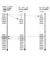
図8は上記の時刻のずれの一例を示し、図の左側が前記内部カウンタの十進数の数値(0〜5000)で示したマスターノードのECUの1ms間隔の時刻(実際の時刻)であり、図8の中央、右側が同様に内部カウンタの十進数の数値(0〜5000)で示したスレーブノードの2つのECU(ECUa、ECUb)の1ms間隔の時刻である。 FIG. 8 shows an example of the time lag described above, and the left side of the figure is the time (actual time) of 1 ms interval of the ECU of the master node indicated by the decimal number (0 to 5000) of the internal counter, The center and the right side of FIG. 8 are the time of 1 ms interval of two ECUs (ECUa, ECUb) of the slave nodes similarly indicated by decimal numbers (0 to 5000) of the internal counter.
そして、マスターノードのECUの「0000」毎に、マスターノードのECUが、その時刻の情報を「現在時刻」の情報としてスレーブノードのECUa、ECUbに送る。このとき、スレーブノードのECUaでは「現在時刻」の情報が届くまでに3つの*印で示す3msの遅れが生じ、スレーブノードのECUbでは「現在時刻」の情報が届くまでに1つの*印で示す1msの遅れが生じたとすると、スレーブノードのECUaの時刻は、実際の時刻に対して、マスターノードのECUの時刻「0003」を時刻「0000」とする3ms遅れの時刻になり、スレーブノードのECUbの時刻は、実際の時刻に対して、マスターノードのECUの時刻「0001」を時刻「0000」とする1ms遅れの時刻になる。 Then, for every “0000” of the master node ECU, the master node ECU sends the time information to the slave nodes ECU a and ECU b as “current time” information. At this time, in the slave node ECUa, a delay of 3 ms indicated by three * marks occurs until the "current time" information arrives, and in the slave node ECUb, one * mark appears until the "current time" information arrives. Assuming that a delay of 1 ms shown occurs, the time of the ECU a of the slave node is a time of 3 ms with the time “0003” of the ECU of the master node being set to “0000” with respect to the actual time. The time of the ECU b is a time that is delayed by 1 ms with respect to the actual time, with the time “0001” of the ECU of the master node being the time “0000”.
この場合、何らかの異常や故障が発生し、例えば実際の時刻「4998」に「DTC」が得られたスレーブノードのECUbが「DTC」とそのときの時刻「4997」を記憶し、それから遅れた実際の時刻「4999」に「DTC」が得られたスレーブノードのECUbが「DTC」とそのときの時刻「4998」を記憶したとすると、ECUbの「DTC」が車内で最も早い実際の時刻「4998」に得られたものであったとしても、ECUbの「DTC」はECUaの「DTC」の後に得られた2番目以降のものであると誤判断されるおそれがある。 In this case, some abnormality or failure occurs, for example, the ECU b of the slave node that obtained “DTC” at the actual time “4998” memorizes “DTC” and the time “4997” at that time, If the ECU b of the slave node that obtained “DTC” at the time “4999” stores “DTC” and the time “4998” at that time, the “DTC” of the ECU b is the earliest actual time “4998” in the vehicle. "DTC" of the ECUb may be erroneously determined as the second and subsequent ones obtained after the "DTC" of the ECUa.
そこで、定期的に(例えば前記の5000ms毎に)、マスターノードのECUとスレーブノードの各ECUとの時間情報のやり取りに基づき、マスターノードのECU、スレーブノードのECUのいずれか一方から送った情報がマスターノードのECU、スレーブノードのECUのいずれか他方に届くまでのオフセット時間を算出し、マスターノードのECUからスレーブノードの各ECUに送る種々の情報に付加される「現在時刻」をオフセット時間で修正した「現在時刻」として、マスターノードのECUとスレーブノードの各ECUとの時刻を合わせることが提案されている(例えば、特許文献1参照)。 Therefore, periodically (for example, every 5000 ms), information sent from either the master node ECU or the slave node ECU based on the exchange of time information between the master node ECU and each slave node ECU. Calculates the offset time until it reaches the other one of the master node ECU and the slave node ECU, and the "current time" added to various information sent from the master node ECU to each slave node ECU is the offset time It has been proposed that the time of the ECU of the master node and each ECU of the slave node be matched as the “current time” corrected in (see, for example, Patent Document 1).
マスターノードとスレーブノードとが通信バスで接続されたCANやLINのようなネットワークにおいて、前記したように、定期的に算出したオフセット時間で修正した「現在時刻」をスレーブノードのECUに送ってマスターノードのECUとスレーブノードのECUとの時刻を合わせたとしても、オフセット時間が次回算出されて更新される前に通信バスを含むスレーブノード側の負荷状況が変化すると、マスターノードのECUが保持するオフセット時間が適切な時間ではなくなり、マスターノードのECUとスレーブノードのECUの時刻がずれてマスターノードのECUとスレーブノードの同期のずれが生じる。なお、この同期のずれを防止するため、マスターノードが保持するオフセット時間を頻繁に算出して更新することが考えられるが、この場合は、そのための時間情報の頻繁なやり取りによって通信バスのバス負荷が高くなり、必要な本来の情報のやり取りに支障をきたし、実用的でない。 In a network such as CAN or LIN in which a master node and a slave node are connected by a communication bus, as described above, the “current time” corrected by the periodically calculated offset time is sent to the ECU of the slave node to be mastered. Even when the time of the ECU of the node and the ECU of the slave node are matched, if the load status on the slave node side including the communication bus changes before the offset time is calculated and updated next time, the master node ECU holds it The offset time is not an appropriate time, and the master node ECU and the slave node ECU are out of time, and the master node ECU and the slave node are out of synchronization. In order to prevent this synchronization shift, it is conceivable that the offset time held by the master node is frequently calculated and updated, but in this case, the bus load of the communication bus is increased by frequent exchange of time information for this purpose. Is not practical because it has hindered the exchange of necessary original information.
本発明は、通信バスのバス負荷を高くすることなく、マスターノードとスレーブノードとの同期のずれを防止することを目的とする。 An object of the present invention is to prevent a synchronization shift between a master node and a slave node without increasing the bus load of a communication bus.
上記した目的を達成するために、本発明の時刻同期システムは、マスターノードとスレーブノードとが通信バスで接続されたネットワークの前記マスターノードから前記スレーブノードに、前記マスターノード、前記スレーブノードのいずれか一方から送った情報が前記マスターノード、前記スレーブノードのいずれか他方に届くまでのオフセット時間で修正した時刻合せ用の現在時刻の情報を送り、前記スレーブノードの時刻を前記スレーブノードが受信した時刻に補正する時刻同期システムにおいて、前記マスターノードは、前記通信バスを含む前記スレーブノード側の負荷状況の変化を検出する検出手段と、前記検出手段が前記スレーブノード側の負荷状況の変化を検出したときに、前記オフセット時間を算出して更新する更新手段とを備えたことを特徴としている。(請求項1)。 In order to achieve the above object, the time synchronization system of the present invention includes a master node and a slave node connected to each other via a communication bus from the master node to the slave node. Sends information on the current time for time adjustment corrected by the offset time until the information sent from either reaches the other of the master node or the slave node, and the slave node received the time of the slave node In the time synchronization system that corrects the time, the master node detects a change in load status on the slave node side including the communication bus, and the detection means detects a change in load status on the slave node side. Updating means for calculating and updating the offset time when It is characterized by comprising. (Claim 1).
請求項1に記載の発明によれば、検出手段の検出に基づき、マスターノードにおいて、通信バスを含むスレーブノード側の負荷状況が変化してオフセット時間が変化するタイミングに合わせて、更新手段がオフセット時間を算出して更新する。 According to the first aspect of the present invention, based on the detection by the detection means, the update means offsets the master node at the timing when the load status on the slave node side including the communication bus changes and the offset time changes. Calculate and update time.
この場合、マスターノードは、通信バスを含むスレーブノード側の負荷状況が変化したときにスレーブノードと通信してオフセット時間を更新することで、通信バスのバス負荷を高くすることなく、常に、適切なオフセット時間を保持することができる。そして、この適切なオフセット時間で修正した時刻合せ用の現在時刻(前記「現在時刻」)の情報をスレーブノードに送ることにより、通信バスのバス負荷を高くすることなく、マスターノードとスレーブノードとの時刻を合わせて同期のずれを防止することができる。 In this case, the master node always communicates with the slave node when the load status on the slave node side including the communication bus changes, and updates the offset time, so that the bus load of the communication bus is always increased appropriately. An accurate offset time can be maintained. Then, by sending information on the current time for time adjustment corrected with the appropriate offset time (said “current time”) to the slave node, the master node and the slave node can be connected without increasing the bus load of the communication bus. Synchronous shifts can be prevented by synchronizing the times.
つぎに、本発明をより詳細に説明するため、本発明の一実施形態について、図1〜図7を参照して詳述する。 Next, in order to describe the present invention in more detail, an embodiment of the present invention will be described in detail with reference to FIGS.
(システムの全体構成)
図1は本実施形態の時刻同期システムが適用される自動車のCANの構成例を示し、1はマスターノードのECUであり、例えば車速やエンジン回転数等の表示を制御するメータ表示制御のECUにより形成される。2a、2b、2c、…はそれぞれスレーブノードのECUであり、例えばCVT制御のECU、燃料噴射制御のECU、ABS(antilocked braking system)制御のECU、…それぞれにより形成される。3は各ECU1、2a、2b、2c、…をつなぐCANの通信バスである。なお、以降は、スレーブノードの各ECUをECU2a〜2cとして説明する。
(Overall system configuration)
FIG. 1 shows a configuration example of a CAN of an automobile to which the time synchronization system of the present embodiment is applied.
そして、マイクロコンピュータ構成のマスターノードのECU1とスレーブノードの各ECU2a〜2cは、CANのシリアル通信プロトコルにしたがって情報をやり取りし、スタンプ機能の後述する同期合せによってスレーブノードの各ECU2a〜2cの時刻をマスターノードのECU1の時刻に同期させる。
Then, the
(マスターノードのECU1の構成)
図2はマスターノードのECU1の一部のブロック構成例を示し、マスターノードのECU1は、随時、各種の命令や「DTC」等のデータ等の本来の情報を通信バス3を通してスレーブノードの各ECU2a〜2cとやり取りするが、マスターノードのECU1がスレーブノードの各ECU2a〜2cに送信する情報は、送信元のノードや情報の区別等のためのID(識別子)が付され、情報バッファ11から送受信処理部12、送受信バッファ13を通って通信バス3に出力される。また、スレーブノードの各ECU2a〜2cから通信バス3に送信された情報は、送受信バッファ13から送受信処理部12を通って情報バッファ11に取り込まれる。
(Configuration of
FIG. 2 shows an example of a block configuration of a part of the
また、マスターノードのECU1は、クロック部14が出力する例えば1msのクロックを時計部15の計時カウンタ16でカウントし、十進数表示でカウント値0〜5000を基本周期とする「現在時刻」を形成する。なお、計時カウンタ16のカウント値が5000になったり、後述するスレーブノード側の負荷状況の変化の検出が行なわれたりすると、計時カウンタ16は0にリセットされるとともに、回数カウンタ17の計時回数が+1カウントアップされる。回数カウンタ17の計時回数は、異なる周期の同じカウント値の「現在時刻」を区別するものである。
Further, the
そして、計時カウンタ16の「現在時刻」および回数カウンタ17の計時回数は、必要に応じてマスター側タイムスタンプ処理部18に取り込まれ、通常制御の情報送信時には、オフセット時間管理部19の後述するオフセット時間で修正した「現在時刻」がマスター側タイムスタンプ処理部18から送受信処理部12に送られて、送信する情報に付加される。なお、オフセット時間の初期算出のための「現在時刻」およびオフセット時間の更新のための「現在時刻」と、通常制御のオフセット時間で修正された「現在時刻」とは、送信する情報に付加される「返信要求」のフラグがセットされているか否かから識別可能である。
Then, the “current time” of the
マスター側タイムスタンプ処理部18は、本発明の検出手段および更新手段を形成する。そして、前記検出手段は、例えば送受信処理部12の情報の送受信頻度や送受信の空き時間等から通信バス3の時々刻々のバス負荷の状況を検出するとともに、例えばスレーブノードのECU別の情報受信速度等からスレーブノードの各ECU2a〜2cの時々刻々の処理負荷の状況を検出し、それらの検出に基づき、例えば時々刻々のバス負荷にスレーブノードの各ECU2a〜2cの時々刻々の処理負荷を加算して、スレーブノードのECU別に通信バスを含む時々刻々のスレーブノード側の負荷状況を把握し、この負荷状況がしきい値以上増減してオフセット時間が所定時間以上増減するときに、スレーブノードのECU別に、通信バス3を含むスレーブノード側の負荷状況の変化を検出する。
The master-side time
マスター側タイムスタンプ処理部18が形成する前記更新手段は、例えば、自動車を最初に始動するIG(イグニッション)オンのときに、スレーブノードのECU2a〜2c毎に、順に、そのときの計時カウンタ16の「現在時刻」(「0000」〜「5000」の情報)を送受信処理部12、送受信バッファ13を介して通信バス3に出力し、スレーブノードのECU2a〜2cの返信が通信バス3から送受信バッファ13、送受信処理部12を介してマスター側タイムスタンプ処理部18に入力されるまでの時間の半分を初期のオフセット時間として算出し、算出した初期のオフセット時間をオフセット時間管理部19に書き込んで保持する。オフセット時間管理部19は、例えばIGオフにより記憶内容が消去されるメモリからなる。
The update means formed by the master time
マスター側タイムスタンプ処理部18が形成する前記更新手段は、算出した初期のオフセット時間を算出した後は、スレーブノードのECU別に通信バス3を含むスレーブノード側の負荷状況の変化が検出される毎に、負荷状況の変化が検出されたスレーブノードのECU2a〜2cに対して、そのときのオフセット時間管理部19のオフセット時間を加算して修正した「現在時刻」の情報を送受信処理部12、送受信バッファ13を介して通信バス3に出力し、スレーブノードの該当するECU2a〜2cの返信が通信バス3から送受信バッファ13、送受信処理部12を介してマスター側タイムスタンプ処理部18に入力されるまでの時間の半分をオフセット時間の増減時間として算出し、算出した増減時間をオフセット時間管理部19に保持されているスレーブノードの該当するECU2a〜2cのオフセット時間に加減して最新の負荷に応じたオフセット時間を算出し、オフセット時間管理部19の該当するECU2a〜2cのオフセット時間を算出したオフセット時間に更新する。
The update means formed by the master side time
(スレーブノードの各ECU2a〜2cの構成)
図3は例えばスレーブノードのECU2aの一部のブロック構成例を示す。スレーブノードの各ECU2a〜2cの図3の一部に該当する部分の構成は略同じである。そして、スレーブノードの各ECU2a〜2cにおいて、マスターノードのECU1から通信バス3に送信された各ECU2a〜2c宛の情報は、各ECU2a〜2cの送受信バッファ21から送受信処理部22を通り、情報バッファ23に取り込まれる。
(Configuration of each
FIG. 3 shows a block configuration example of a part of the
スレーブノードの各ECU2a〜2cがマスターノードのECUに送信する情報は、ID(識別子)が付され、情報バッファ23から送受信処理部22、送受信バッファ21を通って通信バス3に出力される。同様に、スレーブ側タイムスタンプ処理部24の返信の情報もID(識別子)が付され、送受信処理部22、送受信バッファ21を通って通信バス3に出力される。
Information transmitted from each of the
また、スレーブノードの各ECU2a〜2cは、マスターノードのECU1と同様、クロック部25が出力する例えば1msのクロックを時計部26の計時カウンタ27でカウントし、十進数表示でカウント値0〜5000を基本周期とする「現在時刻」の情報を形成する。なお、計時カウンタ27のカウント値が5000になるまでに、マスターノードのECU1からオフセット時間で修正された「現在時刻」を受信すると、計時カウンタ27の「現在時刻」が受信した「現在時刻」(オフセット時間で修正された「現在時刻」)に補正されるともに回数カウンタ28の計時回数が+1カウントアップされる。また、計時カウンタ27のカウント値が5000になると、計時カウンタ27が更新されて0にリセットされるとともに、回数カウンタ17の計時回数が+1カウントアップされる。
Further, each of the
スレーブノードの各ECU2a〜2cのスレーブ側タイムスタンプ処理部24は、受信処理部22が受信した情報から「現在時刻」を取り込み、前記「返信要求」のフラグのセットの有無からか、オフセット時間の初期算出、更新のための「現在時刻」の受信を認識すると、直ちに、受信した「現在時刻」の情報を、そのままマスターノードのECU1に返信する。
The slave time stamp processing unit 24 of each of the
マスターノードのECU1、スレーブノードの各ECU2a〜2cは、上記の構成に基づき、タイムスタンプ機能によるオフセット時間の算出および同期合せの際に、つぎに説明するように動作する。
Based on the above configuration, the
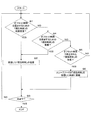
(マスターノードのECU1の動作)
図4はマスターノードのECU1の動作を示し、この動作はIGオンで開始され、最初に、「現在時刻」の情報を初期送信する(ステップS1)、この初期送信に基づくマスターノードの各ECU2a〜2cからの返信を受信すると(ステップS2のYES)、初期送信から返信を受信するまでの時間の半分からオフセット時間を算出してオフセット時間管理部19に初期設定する(ステップS3)。その後、定常制御の情報の送信であれば(ステップS4のYES)、オフセット時間管理部19のオフセット時間で修正した「現在時刻」を情報に付加してスレーブノード側に送信し(ステップS5)、IGオフになるまではステップS6をNOで通過してステップS4から処理をくり返す。
(Operation of the
FIG. 4 shows the operation of the
一方、ステップS4において、通常制御の情報の送信でなければ(ステップS4のNO)、前記検出手段がスレーブノード側の負荷の変化を検出したときに(ステップS7のYES)、オフセット時間を更新するために、そのときの「現在時刻」をオフセット時間管理部19のオフセット時間で修正して送信し(ステップS8)、その返信を受信すると(ステップS2のYES)、送信から返信を受信するまでの時間の半分から最新のオフセット時間を算出してオフセット時間管理部19のオフセット時間を算出した最新のオフセット時間に更新する(ステップS3)。また、本実施形態の場合、前記検出手段がスレーブノード側の負荷の変化を検出しなくても(ステップS7のNO)、従来と同様に計時カウンタ16の計時時刻が5000msに達して「現在時刻」のカウントが一周期する毎に(ステップS9のYES)、そのときの「現在時刻」をオフセット時間管理部19のオフセット時間で修正して送信し(ステップS8)、その返信を受信すると(ステップS2のYES)、送信から返信を受信するまでの時間の半分からオフセット時間を算出してオフセット時間管理部19のオフセット時間を算出したオフセット時間に更新する(ステップS3)。
On the other hand, if the normal control information is not transmitted in step S4 (NO in step S4), the offset time is updated when the detection unit detects a change in the load on the slave node side (YES in step S7). Therefore, the “current time” at that time is corrected with the offset time of the offset
(スレーブノードのECU2a〜2cの動作)
図5はスレーブノードのECU2a〜2cの動作を示し、スレーブノードのECU2a〜2cは、オフセット時間を算出するための「現在時刻」を初期受信すると(ステップQ1のYES)、受信した「現在時刻」をマスターノードのECU1に返信し(ステップQ2)、IGオフになるまではステップQ3をNOで通過してステップQ1に戻る。
(Operations of the
FIG. 5 shows the operation of the
また、オフセット時間を更新するための「現在時刻」を受信したときにも(ステップQ1のNO、ステップQ4のYES)、受信した「現在時刻」をマスターノードのECU1に返信し(ステップQ2)、IGオフになるまではステップQ3をNOで通過してステップQ1に戻る。
Also, when the “current time” for updating the offset time is received (NO in step Q1, YES in step Q4), the received “current time” is returned to the
つきに、通常制御の情報の受信等により、オフセット時間で修正された「現在時刻」を受信すると(ステップQ1、Q2のNO、ステップQ3のYES)、計時カウンタ27の「現在時刻」を受信した「現在時刻」に補正し、時刻合せを行なってマスターノードとステップの同期をとる(ステップQ6)。その後、ステップQ3に移行する。
Finally, when the “current time” corrected by the offset time is received by receiving normal control information or the like (NO in steps Q1, Q2 and YES in step Q3), the “current time” of the
つぎに、マスターノードのECU1、スレーブノードの各ECU2a〜2cの動作に基づく、マスターノードとスレーブノードの同期合せの一例について説明する。
Next, an example of synchronization between the master node and the slave node based on the operations of the
図6はマスターノードとスレーブノードの同期合せのタイムチャートの一例を示し、説明を簡単にするため、スレーブノードのECUをECU2aとすると、IGオンまたはスレーブノード側の負荷状況の変化に基づき、時刻t1にマスターノードのECU1がオフセット時間の初期算出または更新のために「現在時刻」を送信することにより(図6の工程#1)、時刻t2にスレーブノードのECU2aが受信した「現在時刻」をそのまま返信する(図6の工程#2)。この返信が時刻t3にマスターノードのECU1に受信されると、マスターノードのECU1は送信した「現在時刻」と、返信の「現在時刻」を受信したときの自己の「現在時刻」(最新の「現在時刻」)との差分を算出し(図6の工程#3)、時刻t4に、算出した差分の時間の半分の時間をオフセット時間として算出する(図6の工程#4)。なお、更新の場合は算出した差分の時間の半分が既に算出されているオフセット時間の増減時間になり、この増減時間を既に算出されているオフセット時間に加えて最新のオフセット時間が算出される。ここまでが、図6のオフセット時間算出の処理である。
FIG. 6 shows an example of a time chart of synchronization between the master node and the slave node. For simplicity of explanation, when the ECU of the slave node is
そして、算出された最新のオフセット時間はマスターノードのECU1のオフセット時間管理部19に保持されて管理され、図6の定常制御の処理において、オフセット時間で修正された「現在時刻」が時刻t5にマスターノードのECU1から送信されると(図6の工程#5)、時刻t6にそれを受信したスレーブノードのECU2aが自己の「現在時刻」を受信した「現在時刻」に置換してマスターノードとスレーブノードの同期処理を行なって時刻を合せる(図6の工程#6)。
Then, the calculated latest offset time is held and managed by the offset
以降、スレーブノード側でフェールが発生したり、処理負荷が高くなったりして、スレーブノード側の負荷状況が変化すると、工程#1〜#4によってマスターノードのECU1のオフセット時間管理部19に保持されているオフセット時間が最新の負荷状況に即したオフセット時間に更新される。
Thereafter, when a failure occurs on the slave node side or a processing load increases, and the load state on the slave node side changes, the offset
図7はこのようにして同期合せを行なった場合のタイムスタンプ例を示し、ここでは、スレーブノードのECUを図8の従来例に合わせて、ECU2a、ECU2bとし、マスターノードのECU1の内部カウンタとしての計時カウンタ16の「現在時刻」に対して、スレーブノードのECU2a、2bの内部カウンタとしての計時カウンタ16の「現在時刻」が、図8の場合と同様に3ms、1ms遅れているとする。なお、*等は図8と同じものを示す。
FIG. 7 shows an example of a time stamp when synchronization is performed in this manner. Here, the ECUs of the slave nodes are
この場合、マスターノードのECU1がスレーブノードのECU2a、2bに送信する時刻合せ用の「現在時刻」が、ECU2a、2bの負荷状況に応じたオフセット時間3ms、1msで修正されて3ms、1ms進んだ時刻になるので、マスターノードのECU1の時刻(実際の時刻)にスレーブノードのECU2a、2bの時刻がずれなく同期する。そのため、車内に何らかの異常や故障が発生すると、例えば、実際の時刻「4998」に「DTC」が得られたスレーブノードのECU2aが「DTC」とそのときの時刻「4998」を記憶し、それから遅れた実際の時刻「4999」に「DTC」が得られたスレーブノードのECU2bが「DTC」とそのときの時刻「4999」を記憶するので、ECU2aの「DTC」が車内で最も早い実際の時刻「4998」に得られ、ECU2bの「DTC」がECU2aの「DTC」の後に得られた2番目以降のものであると正しく判断される。
In this case, the “current time” for time adjustment transmitted from the
以上説明したように、本実施形態の場合、マスターノードのECU1の前記検出手段が、スレーブノードのECU2a〜2c毎に通信バス3を含むスレーブノード側の負荷状況の変化を検出し、マスターノードのECU1の前記更新手段が、スレーブノードのECU2a〜2cそれぞれのスレーブノード側の負荷状況の変化を検出したときに、ECU2a〜2cそれぞれのオフセット時間を算出して更新するため、マスターノードのECU1は、スレーブノードのECU2a〜cと頻繁に通信することなく、スレーブノードのECU2a〜2cそれぞれのスレーブノード側の負荷状況が変化して適切なオフセット時間が変化するタイミングに合わせて、ECU2a〜2cそれぞれのオフセット時間を算出して負荷状況に応じた適切なオフセット時間に更新することができる。
As described above, in the case of the present embodiment, the detection means of the
この場合、マスターノードのECU1は、通信バス3のバス負荷を高くすることなく、常に、スレーブノードのECU2a〜2cそれぞれの適切なオフセット時間をオフセット時間管理部19に保持して管理することができる。そして、通常制御の情報送信時等に、マスターノードのECU1からスレーブノードのECU2a〜2cに、それぞれの適切なオフセット時間で修正した「現在時刻」をスレーブノードに送ることにより、通信バス3のバス負荷を高くすることなく、タイムスタンプ機能によってマスターノードとスレーブノードとの時刻を正確に合わせて同期のずれを防止することができる。そのため、例えばスレーブノードのECU2a〜2cが「DTC」とともに記憶した時刻から車内の異常や故障の発生個所を迅速・正確に突き止めて明確にすること等ができる。
In this case, the
そして、本発明は上記した実施形態に限定されるものではなく、その趣旨を逸脱しない限りにおいて上述したもの以外に種々の変更を行なうことが可能であり、例えば、前記実施形態では、スレーブノード側の負荷状況の変化を検出しなくても、従来と同様にマスターノードのECU1の計時カウンタ16が「現在時刻」の1周期である5000msを計時したときにはオフセット時間を算出して更新するようにしたが、通信バス3のバス負荷の一層の軽減等を図る場合には、スレーブノード側の負荷状況の変化を検出したときのみオフセット時間を算出して更新するようにしてもよい。
The present invention is not limited to the above-described embodiment, and various modifications other than those described above can be made without departing from the spirit thereof. For example, in the above-described embodiment, the slave node side Even if a change in the load status of the current time is not detected, the offset time is calculated and updated when the
また、計時カウンタ16、27の最大のカウント時間やクロックの周期等は、システムに応じた適当なものであってよく、前記実施形態の5000、1msに限るものではない。 Further, the maximum count time of the time counters 16 and 27, the clock cycle, and the like may be appropriate according to the system, and are not limited to 5000 and 1 ms in the above embodiment.
さらに、マスターノードのECU1およびスレーブノードのECU2a〜2cの構成は図2、図3の構成に限るものではなく。通信バス3がLIN等の通信バスであってもよい。
Furthermore, the configuration of the
つきに、スレーブノードのECU2a〜2cは、通信バス3を介して、スレーブノード間で通信することがあってもよいのは勿論であり、スレーブノードのECU2a〜2cは1つ以上であればよい。
In the meantime, the
そして、マスターノード、スレーブノードはECUで構成されるものに限るものではなく、本発明は、種々の機器や設備のマスターノードとスレーブノードとが通信バスで接続されたネットワークの時刻同期システムに適用することができる。 The master node and the slave node are not limited to those configured by the ECU, and the present invention is applied to a network time synchronization system in which a master node and a slave node of various devices and facilities are connected by a communication bus. can do.
1 マスターノードのECU
2a〜2c スレーブノードのECU
3 通信バス
16、27 計時カウンタ
18 マスター側タイムスタンプ処理部
19 オフセット時間管理部
1 Master node ECU
2a to 2c Slave node ECU
3
Claims (1)
前記マスターノードは、
前記通信バスを含む前記スレーブノード側の負荷状況の変化を検出する検出手段と、
前記検出手段が前記スレーブノード側の負荷状況の変化を検出したときに、前記オフセット時間を算出して更新する更新手段とを備えたことを特徴とする時刻同期システム。 Information sent from either the master node or the slave node to the slave node from the master node of the network in which the master node and the slave node are connected via a communication bus is either the master node or the slave node. In the time synchronization system that sends the current time information for time adjustment corrected by the offset time until it reaches the other, and corrects the time of the slave node to the time received by the slave node,
The master node is
Detecting means for detecting a change in load status on the slave node side including the communication bus;
A time synchronization system comprising: an updating unit that calculates and updates the offset time when the detecting unit detects a change in load status on the slave node side.
Priority Applications (1)
| Application Number | Priority Date | Filing Date | Title |
|---|---|---|---|
| JP2011041285A JP2012178770A (en) | 2011-02-28 | 2011-02-28 | Time synchronizing system |
Applications Claiming Priority (1)
| Application Number | Priority Date | Filing Date | Title |
|---|---|---|---|
| JP2011041285A JP2012178770A (en) | 2011-02-28 | 2011-02-28 | Time synchronizing system |
Publications (1)
| Publication Number | Publication Date |
|---|---|
| JP2012178770A true JP2012178770A (en) | 2012-09-13 |
Family
ID=46980313
Family Applications (1)
| Application Number | Title | Priority Date | Filing Date |
|---|---|---|---|
| JP2011041285A Pending JP2012178770A (en) | 2011-02-28 | 2011-02-28 | Time synchronizing system |
Country Status (1)
| Country | Link |
|---|---|
| JP (1) | JP2012178770A (en) |
Cited By (5)
| Publication number | Priority date | Publication date | Assignee | Title |
|---|---|---|---|---|
| US10442297B2 (en) | 2017-05-24 | 2019-10-15 | Toyota Motor Engineering & Manufacturing North America, Inc. | Fuel cell vehicle with power modules |
| US10518652B2 (en) | 2017-05-24 | 2019-12-31 | Toyota Motor Engineering & Manufacturing North America, Inc. | Fuel cell vehicle with power modules |
| JP2020527316A (en) * | 2017-07-21 | 2020-09-03 | ロベルト・ボッシュ・ゲゼルシャフト・ミト・ベシュレンクテル・ハフツングRobert Bosch Gmbh | Time stamp unit and communication control unit for subscriber stations of communication networks |
| US10793157B2 (en) | 2017-05-24 | 2020-10-06 | Toyota Motor Engineering & Manufacturing North America, Inc. | Operating electrified vehicles during traction events |
| WO2022215359A1 (en) * | 2021-04-09 | 2022-10-13 | パナソニックIpマネジメント株式会社 | Communication system, master device, slave device, and control method for communication system |
Citations (3)
| Publication number | Priority date | Publication date | Assignee | Title |
|---|---|---|---|---|
| JPH05161181A (en) * | 1991-12-10 | 1993-06-25 | Nec Corp | Time synchronization system |
| JPH11223687A (en) * | 1998-02-09 | 1999-08-17 | Hitachi Ltd | Synchronizing system for internal timepieces among plural computers |
| JP2003298630A (en) * | 2002-04-01 | 2003-10-17 | Mitsubishi Electric Corp | Time synchronization method |
-
2011
- 2011-02-28 JP JP2011041285A patent/JP2012178770A/en active Pending
Patent Citations (3)
| Publication number | Priority date | Publication date | Assignee | Title |
|---|---|---|---|---|
| JPH05161181A (en) * | 1991-12-10 | 1993-06-25 | Nec Corp | Time synchronization system |
| JPH11223687A (en) * | 1998-02-09 | 1999-08-17 | Hitachi Ltd | Synchronizing system for internal timepieces among plural computers |
| JP2003298630A (en) * | 2002-04-01 | 2003-10-17 | Mitsubishi Electric Corp | Time synchronization method |
Cited By (6)
| Publication number | Priority date | Publication date | Assignee | Title |
|---|---|---|---|---|
| US10442297B2 (en) | 2017-05-24 | 2019-10-15 | Toyota Motor Engineering & Manufacturing North America, Inc. | Fuel cell vehicle with power modules |
| US10518652B2 (en) | 2017-05-24 | 2019-12-31 | Toyota Motor Engineering & Manufacturing North America, Inc. | Fuel cell vehicle with power modules |
| US10793157B2 (en) | 2017-05-24 | 2020-10-06 | Toyota Motor Engineering & Manufacturing North America, Inc. | Operating electrified vehicles during traction events |
| JP2020527316A (en) * | 2017-07-21 | 2020-09-03 | ロベルト・ボッシュ・ゲゼルシャフト・ミト・ベシュレンクテル・ハフツングRobert Bosch Gmbh | Time stamp unit and communication control unit for subscriber stations of communication networks |
| US11258633B2 (en) | 2017-07-21 | 2022-02-22 | Robert Bosch Gmbh | Timestamp unit and communication control unit for a user station of a communication network |
| WO2022215359A1 (en) * | 2021-04-09 | 2022-10-13 | パナソニックIpマネジメント株式会社 | Communication system, master device, slave device, and control method for communication system |
Similar Documents
| Publication | Publication Date | Title |
|---|---|---|
| CN111264039B (en) | Method for detecting an incorrect time stamp of an ethernet message and control unit for a motor vehicle | |
| US11218238B2 (en) | Method, computer-readable medium, system, and vehicle comprising the system for validating a time function of a master and the clients in a network of a vehicle | |
| US7848360B2 (en) | Method for transmitting synchronization messages in a communication network | |
| US7171573B2 (en) | Synchronization of data processing units | |
| JP6523497B1 (en) | Master controller and synchronous communication system using the same | |
| JP2012178770A (en) | Time synchronizing system | |
| JP2007060400A (en) | Method and system for controlling communication timing | |
| US20210288736A1 (en) | Method, device, and computer program for improving synchronization of clocks in devices linked according to a daisy-chain topology | |
| CN104113386A (en) | Method and device for monitoring Ethernet clock synchronization | |
| US20210258136A1 (en) | Time synchronisation | |
| US11522778B2 (en) | Method for determining a synchronization accuracy, computer program, communication unit and motor vehicle | |
| CN108139945B (en) | Vehicle safety electronic control system | |
| US9713109B2 (en) | Method for locating a frequency deviation in a communication network, and corresponding communication network | |
| CN104243079A (en) | Microsecond clock synchronization method for real-time Ethernet | |
| KR20030084984A (en) | Method and device for synchronizing at least one node of a bus system and a corresponding bus system | |
| CN112448874B (en) | Vehicle-mounted communication device and time synchronization method thereof | |
| Akpinar et al. | Improved clock synchronization algorithms for the controller area network (CAN) | |
| JP5643240B2 (en) | Time setting method, communication device, and time setting program | |
| CN115362642A (en) | Method and system for performing time synchronization between units of a communication bus system | |
| CN111357243A (en) | User device of bus system, operation method and bus system | |
| JP2023506907A (en) | A Method for Validating Sensor Data Validity in Ethernet Onboard Networks | |
| Do et al. | Time synchronization method between CAN-FD nodes | |
| CN114499734B (en) | Communication clock synchronization method, system and equipment based on PTP | |
| KR20180090109A (en) | Clock synchronization system improved clock accuracy through competition with Grand Master clocks | |
| CN114375552B (en) | Method for time synchronization in Ethernet-based network |
Legal Events
| Date | Code | Title | Description |
|---|---|---|---|
| A621 | Written request for application examination |
Free format text: JAPANESE INTERMEDIATE CODE: A621 Effective date: 20140227 |
|
| A977 | Report on retrieval |
Free format text: JAPANESE INTERMEDIATE CODE: A971007 Effective date: 20150115 |
|
| A131 | Notification of reasons for refusal |
Free format text: JAPANESE INTERMEDIATE CODE: A131 Effective date: 20150127 |
|
| A521 | Request for written amendment filed |
Free format text: JAPANESE INTERMEDIATE CODE: A523 Effective date: 20150310 |
|
| A02 | Decision of refusal |
Free format text: JAPANESE INTERMEDIATE CODE: A02 Effective date: 20150929 |